EP2451663B1 - Belüftungssystem für nutzfahrzeuge - Google Patents
Belüftungssystem für nutzfahrzeuge Download PDFInfo
- Publication number
- EP2451663B1 EP2451663B1 EP10752387.0A EP10752387A EP2451663B1 EP 2451663 B1 EP2451663 B1 EP 2451663B1 EP 10752387 A EP10752387 A EP 10752387A EP 2451663 B1 EP2451663 B1 EP 2451663B1
- Authority
- EP
- European Patent Office
- Prior art keywords
- filter
- air
- utility vehicle
- vehicle according
- channel
- Prior art date
- Legal status (The legal status is an assumption and is not a legal conclusion. Google has not performed a legal analysis and makes no representation as to the accuracy of the status listed.)
- Not-in-force
Links
Images


Classifications
-
- B—PERFORMING OPERATIONS; TRANSPORTING
- B60—VEHICLES IN GENERAL
- B60H—ARRANGEMENTS OF HEATING, COOLING, VENTILATING OR OTHER AIR-TREATING DEVICES SPECIALLY ADAPTED FOR PASSENGER OR GOODS SPACES OF VEHICLES
- B60H3/00—Other air-treating devices
- B60H3/06—Filtering
- B60H3/0608—Filter arrangements in the air stream
- B60H3/0633—Filter arrangements in the air stream with provisions for regenerating or cleaning the filter element
-
- B—PERFORMING OPERATIONS; TRANSPORTING
- B60—VEHICLES IN GENERAL
- B60H—ARRANGEMENTS OF HEATING, COOLING, VENTILATING OR OTHER AIR-TREATING DEVICES SPECIALLY ADAPTED FOR PASSENGER OR GOODS SPACES OF VEHICLES
- B60H1/00—Heating, cooling or ventilating devices
- B60H1/00357—Air-conditioning arrangements specially adapted for particular vehicles
- B60H1/00378—Air-conditioning arrangements specially adapted for particular vehicles for tractor or load vehicle cabins
-
- B—PERFORMING OPERATIONS; TRANSPORTING
- B60—VEHICLES IN GENERAL
- B60H—ARRANGEMENTS OF HEATING, COOLING, VENTILATING OR OTHER AIR-TREATING DEVICES SPECIALLY ADAPTED FOR PASSENGER OR GOODS SPACES OF VEHICLES
- B60H3/00—Other air-treating devices
- B60H3/06—Filtering
- B60H3/0608—Filter arrangements in the air stream
- B60H3/0641—Filter arrangements in the air stream near ventilating openings in the vehicle exterior
Definitions
- the invention relates to ventilation systems fitted to the cabs of utility vehicles, such as tractors, combine harvesters and plant machinery, said system serving to receive air from the environment, filter the air and supply the filtered air into the cab.
- Utility vehicles are often required to work in dusty environments.
- the cab in which the driver sits is typically fitted with a ventilation system which ensures the comfort and safe working environment for the driver.
- the filter, or filters, of the ventilation system often require routine cleaning or replacement. The period between filter servicing is significantly reduced when working in extremely dusty environments. In some cases, the filter requires attention several times a day leading to unacceptable downtime.
- the filter is often housed in such a way which requires the removal of several components to gain access thereto.
- FR-2,501,340 discloses an example utility vehicle comprising a ventilation system having a pre-filter upstream of a main filter.
- a utility vehicle comprising a ventilation system which receives air from the environment, filters the air and supplies the filtered air into a cab, the system comprising a fan to drive air through a channel from the environment to the cab, a main air filter arranged within a roof section of the cab and downstream of a pre-filter which rotates about a rotation axis which is substantially parallel to the air flow through the pre-filter.
- the rotation of the pre-filter reduces the particulate build up thereon due to the radial air flow created and the centrifugal forces exerted on the incident dust. Furthermore, the majority of the dust is removed from the air flow before reaching the main filter. Therefore, removal of the main filter is seldom required.
- the pre-filter can be located externally of the roof structure. This is particularly advantageous on a utility vehicle because maintenance (e.g. clearing) of the pre-filter does not require the time-consuming removal of components associated with the main cab structure.
- the pre-filter is mounted to an electric motor and, preferably, the electric motor is dedicated to rotating the pre-filter.
- the pre-filter is driven by a hydraulic motor or air-driven turbine.
- the channel immediately downstream of the pre-filter has a diameter which is less than the diameter of the pre-filter.
- the particulate removal effect is significantly improved.
- the dust thrown off of the periphery of the pre-filter is not reintroduced into the clean air flow. Instead, the removed dust is thrown against a wall of the channel and/or thrown out of a pre-filter module away from the intake air flow.
- the fan is preferably located downstream of the pre-filter and, preferably further still, downstream of the main filter. Therefore, the air is sucked through at least one of the pre-filter and main filter before being propelled into the cab.
- the fan is preferably driven by a dedicated electric motor.
- the system may further comprise an air conditioning evaporator to cool the air. This may be disposed in the air stream between the main filter and fan for example.
- the roof section of the cab is at least partly formed of moulded plastic and at least a portion of the channel is defined by channel elements moulded into the roof section.
- this reduces the number of components required to provide the ducting which channels the air between the various system elements.
- the channel preferably includes a recycle inlet through which recycled air from the cab is drawn, the recycle inlet being closable by a blocking element which is moveable between a normal position and a recycle position wherein the channel upstream of the recycle inlet is blocked to prevent the intake of air from the environment.
- a blocking element which is moveable between a normal position and a recycle position wherein the channel upstream of the recycle inlet is blocked to prevent the intake of air from the environment.
- this provides the option to block the intake of air from the surroundings. For example, this may be preferred when spraying chemicals on a crop field.
- the recycle inlet is preferably located upstream of the main filter and downstream of the pre-filter filter. This ensures continued filtering of the recycled air whilst allowing easy access to and/or removal of the pre-filter.
- the rotation axis is substantially vertical.
- this encourages the particulate matter collected by the pre-filter to fall under gravity away therefrom, thereby increasing the period between maintenance.
- the pre-filter and motor is preferably housed within a pre-filter housing which includes a covering inlet vent upstream of the pre-filter.
- the covering inlet vent may be removable to enable easy access to the pre-filter for cleaning and replacement.
- a portion of the channel between the main filter and pre-filter may be integrated within the roof section. This may leave only the pre-filter housing to be attached to the roof thus minimising components whilst enabling easy access to maintain the pre-filter.
- the pre-filter and motor may be integrated into a detachable pre-filter module which is mounted to the roof section.
- this allows an existing utility vehicle, with a conventional ventilation system, to be simply modified with the attachment of the pre-filter module. This minimises expense in that no modifications are necessary to the hardware of existing vehicles.
- the pre-filter module can be offered to the customers of vehicle manufacturers as an optional extra. In this case, the module can be added to the vehicle late in the assembly process, thus minimising any changes to the existing assembly line.
- the pre-filter module may include a channel portion downstream of the pre-filter having an outlet orifice which cooperates with an inlet vent formed in a face of the roof section. This enables simple attachment of the module to the roof section.
- a releasable wired link may be provided to releasably connect the motor to a power source located on the vehicle. Therefore, installation of the module simply involves the attachment of the module to the vehicle and then connection of the wired link to provide power to the motor.
- a tractor 10 comprises a pair of front steerable wheels 12 mounted on respective ends of a front axle 13, and a pair of rear wheels 14 which are at least partially covered by rear wheel fenders 15.
- a driver sits in a driver's seat 16, the space around which is protected by cab 18.
- a roll-over protection structure provides a framework for the cab 18 and includes a pair of front A-pillars 20, a pair of intermediate B-pillars 21, and a pair of rear C-pillars 22.
- the ROPS further includes a front generally transverse member 26, a rear generally transverse member 27 and a pair of generally longitudinal members 28 the combination of which provides a rigid support frame for the roof 24,25 and ventilation system to be described below.
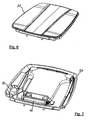
- the tractor roof section includes a top moulded portion 25 and a bottom moulded portion 24 which are formed, for example, by blow-moulding plastic and cover the components of the ventilation system. It should be understood that the top roof section 25 is not shown in Figures 3 , 4 , 5 and 7 .
- the ventilation system Starting at the inlet of air, the ventilation system, referenced generally at 30, comprises a pre-filter 32 which is housed within a pre-filter unit 33.
- pre-filter unit 33 The construction and operation of pre-filter unit 33 will be described in more detail below.
- the pre-filter unit 33 is mounted to a first ducting section 34 which conveys the air-stream from pre-filter unit 33 to a main filter unit 35, the latter housing a main filter (not shown) through which the ventilation air-stream passes.
- the first ducting section 34 sealably connects to the main filter housing 35 by a generally rectangular attachment interface 36 which includes securing means (not shown) to hold the first ducting member 34 in position.
- this connection may be a simple male/female connection with the male part being associated with the first ducting section.
- the main filter contained within main filter unit 35 is formed of a fibrous material and serves to trap dust and particulate matter, thereby cleaning the air which has been drawn in from the environment via the pre-filter unit 33.
- a cover 38 is pivotally connected by hinges 39 to the top roof section 25.
- the cover 38 hinges upwardly and provides simple access to the pre-filter unit 33 for maintenance thereof. Furthermore, the main filter housing can be simply accessed by removal of first ducting section 34. To conceal the pre-filter unit 33 and first ducting section 34, the cover 38 conforms with the profile of the roof 24.
- a cover 40 encloses the pre-filter 32 and pivots downwardly to give access thereto.
- the air leaves the main filter unit 35 through outlet 42 ( Figure 4 ) and passes into a junction chamber 44.
- a flap 45 is movable between a normal position and a recycle position. In the recycle position (shown in Figures 3 and 4 ) the incoming air from outlet 42 is blocked and recycled air is allowed to pass from the cab interior via a cycle inlet 46 on to the H-vac unit 50. In the normal position the flap 45 serves to partially block the air from the recycle unit 46 and allow the filtered air from the main filter housing 35 to pass into a heating, ventilation and air conditioning (HVAC) unit 50. Typically, the normal position allows a mixture of 50% fresh air and 50% recycled air to pass into the HVAC unit 50.
- HVAC heating, ventilation and air conditioning
- the air-stream is conveyed from the junction housing 44 to the HVAC unit 50 by a second ducting section which is formed from side-walls 52 which are integrated into the overall roof structure.
- HVAC unit 50 is of a known type and includes a heater element to heat the air-stream when required, and an evaporator 54 which serves to cool the air-stream when required.
- the HVAC unit 50 is integrated into the bottom roof member 24, is secured to the rear transverse cab member 27 and is enclosed within the roof space formed between top roof member at 25 and the bottom roof member 24.
- the HVAC unit 50 serves as a heat exchanger through which the filtered air can be either heated or cooled as required.
- a pair of blowers 54 are arranged on the downstream side of the HVAC unit 50 and provide the propulsive force which draws in air from the environment and forces it out into the driver's cab 18.
- a dividing wall 55 splits the air-stream into a left-hand and right-hand sub-stream each having a respective blower 54.
- Each sub-stream of air is delivered into the cab 18 by third and fourth ducting sections 56, 57 having integrated air vents 58.
- the air-flow speed can be adjusted by the driver by appropriate control of the blower speed. Furthermore, the driver can tailor the clean air distribution by appropriate adjustment of the individual vents 58. The temperature of the air can be adjusted by appropriate control of the HVAC unit 50.
- the above-described arrangement includes a pre-filter unit 33 and first ducting member 34 which is integrated inside the profile of the roof 24 so as to conceal the presence thereof. These components can be added during assembly of the vehicle or at a later stage. However, it is envisaged that a pre-filter unit can be added as part of an additional module to a utility vehicle having a main filter only.
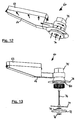
- FIGS 11 - 14 illustrate a second embodiment of the invention wherein a pre-filter module 60 is secured to an air intake of an existing utility vehicle ventilation system.
- a male flange 62 provides an extension of a first ducting section 64 and inserts into the intake vent (not shown) of a tractor's ventilation system which is located on the underside (overhang) of a cab roof externally of the driver's space.
- Locking screws 65 are provided to secure the pre-filter module 60 to the tractor.
- a pre-filter element 72 is housed within a pre-filter unit 73 which is connected to the first ducting member 64 so as to allow filtered air to pass from the pre-filter unit 73 into the tractor's ventilation system.
- the pre-filter element 72 is mounted on a shaft 74 which is connected to an electrical motor (not shown) which is housed within motor housing 75.
- the pre-filter element 72 is secured in fixed engagement with shaft 74 by locking nuts 76.
- a centring rod 77 is secured to the underside of flange 78 and serves as a guide for the shaft 74 to ensure that the latter maintains a central position.
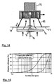
- Flange 78 is annular in shape and includes an air intake orifice 80 which has a diameter less than that of the pre-filter element 72.
- pre-filter element 72 is held in close engagement with the flange 78 and the outside edge of pre-filter 72 overlaps the edge of inlet orifice 80 by a distance X.
- the pre-filter element 72 is rotated at a speed of approximately 1500-3000 rpm by the electrical motor.
- Air is drawn in through the rotating pre-filter element 72 and passes into a conical transfer housing 82 before being conveyed at 90° into first ducting section 64.
- the rotational motion of pre-filter element 72 creates a proximate radial airflow which forces particulate matter radially outwardly so as not to collect on the surface of pre-filter element 72. Due to the overlap X between the pre-filter element 72 and intake orifice 82 there is minimal airflow through the peripheral region of the former.
- the blocked particulate matter eventually falls downwardly due to gravity when it reaches the edge of pre-filter element 72.
- the substantially vertical orientation of the pre-filter exploits gravity to remove the blocked particulate matter.
- the overlap X prevents the ingress of particulate matter around the outside of pre-filter element 72, by effectively producing a labyrinth seal. Also, a subsidiary radial airflow exists between the pre-filter element 72 and the flange 78 which also blocks the particulate matter.
- pre-filter element 72 is enclosed by a perforated cover (not shown) for safety reasons.
- first ducting member 64 requires appropriate design in order to maintain a vertical rotation axis for the pre-filter element whilst enabling simple addition of the module to an existing system.
- the arrangement shown in Figures 12 - 14 is suitable for a tractor having an inlet vent which receives a vertical airflow.
- a pre-filter module may be designed to cater for an air intake which is horizontal in nature and is comparable to the pre-filter unit 33 and first ducting member 34 of the embodiment shown in Figures 2 - 10 .
- the motor housed within motor housing 75 is connected to a power supply by a detachable lead (not shown).
- a detachable lead (not shown).
- the integrated version shown in Figures 2 - 10 may include a hard wiring which does not require routine detachment.
- the male/female connection of the attachment interface 36 may include an integrated electrical connection to supply power from the vehicle to the pre-filter unit.
- the invention can be integrated into a new ventilation system for a tractor cab or, alternatively, achieved by providing an additional unit to an existing ventilation system.
- the pre-filter module 60 may be readily attached and detached to suit the operating conditions on a daily basis. For example, this allows a farmer to attach the pre-filter module when working in a dusty environment and detach the pre-filter module when not required so as to reduce the profile of the overall tractor.
- inventive ventilation system can be applied to other utility vehicles such as plant machinery and combine harvesters without deviating from the scope of the invention.
- the rotating pre-filter element described above in relation to the appended drawings is driven by an electric motor.
- the pre-filter element may be rotated by other means including a hydraulic motor or even an integrated turbine which is driven by the airflow through the ventilation system.
- a fan is disposed on the same shaft as the rotating pre-filter wherein the electric motor drives both elements.
- this provides additional propulsion to the air stream through the ventilation system.
- a utility vehicle comprising a ventilation system which receives air from the environment, filters the air and supplies the filtered air into a cab.
- the system comprises a fan to drive air through a channel from the environment to the cab, and a main air filter arranged within a roof section of the cab and downstream of a pre-filter.
- the pre-filter rotates about a rotation axis which is substantially parallel to the air flow through the pre-filter so as to reduce the particulate matter which reaches the main filter.
- the rotation of the pre-filter creates a centrifugal force and tangential airflow which forces the particulate matter radially outwardly to reduce the build-up of matter on the filter, thus reducing the frequency of servicing.
- the pre-filter can be integrated into a cab ventilation system or provided in a module which can be added to a vehicle having a conventional ventilation system.
Landscapes
- Engineering & Computer Science (AREA)
- Mechanical Engineering (AREA)
- Physics & Mathematics (AREA)
- Thermal Sciences (AREA)
- Air-Conditioning For Vehicles (AREA)
Claims (15)
- Nutzfahrzeug (10) mit einem Belüftungssystem (30), das Luft aus der Umgebung empfängt, die Luft filtert und die gefilterte Luft einer Kabine (18) zuführt, wobei das System einen Ventilator (54) zum Bewegen von Luft aus der Umgebung durch einen Kanal in die Kabine und ein Hauptluftfilter (35) aufweist, das in einem Dachabschnitt (24) der Kabine und stromabwärts eines Vorfilters (32; 72) angeordnet ist, dadurch gekennzeichnet, dass das Vorfilter (32; 72) an einem elektrischen Motor montiert ist, der das Vorfilter um eine im Wesentlichen parallel zu dem Luftstrom durch das Vorfilter verlaufende Drehachse dreht, und wobei das Belüftungssystem weiterhin einen ergänzenden Ventilator aufweist, der sich um die Drehachse dreht und durch den elektrischen Motor angetrieben ist.
- Nutzfahrzeug nach Anspruch 1, wobei der direkt stromabwärts des Vorfilters angeordnete Kanal einen kleineren Durchmesser als der Vorfilter besitzt.
- Nutzfahrzeug nach einem der vorhergehenden Ansprüche, wobei der Ventilator (54) stromabwärts des Vorfilters angeordnet ist.
- Nutzfahrzeug nach Anspruch 3, wobei der Ventilator (54) stromabwärts des Hauptfilters (35) angeordnet ist.
- Nutzfahrzeug nach einem der vorhergehenden Ansprüche, wobei das System weiterhin einen Klimaanlagen-Verdampfer zum Kühlen der Luft aufweist.
- Nutzfahrzeug nach einem der vorhergehenden Ansprüche, wobei der Dachabschnitt der Kabine zumindest teilweise aus geformtem Kunststoff gebildet ist und mindestens ein Teil des Kanals durch in dem Dachabschnitt geformte Kanalelemente gebildet wird.
- Nutzfahrzeug nach einem der vorhergehenden Ansprüche, wobei der Kanal einen Umwälzeinlass (46) aufweist, durch den umgewälzte Luft aus der Kabine eingezogen wird, wobei der Umwälzeinlass durch ein Blockierelement (45) schließbar ist, wobei das Blockierelement (45) zwischen einer normalen Stellung und einer Umwälzstellung bewegbar ist, wobei der Kanal in der Umwälzstellung stromaufwärts des Umwälzeinlasses blockiert ist, um das Einziehen von Luft aus der Umgebung zu verhindern.
- Nutzfahrzeug nach Anspruch 7, wobei der Umwälzeinlass stromaufwärts des Hauptfilters und stromabwärts des Vorfilters angeordnet ist.
- Nutzfahrzeug nach einem der vorhergehenden Ansprüche, wobei die Rotationsachse im Wesentlichen vertikal verläuft.
- Nutzfahrzeug nach einem der vorhergehenden Ansprüche, wobei das Vorfilter und der Motor in einem Vorfiltergehäuse angeordnet sind, das stromaufwärts des Vorfilters eine Lufteinlassabdeckung aufweist.
- Nutzfahrzeug nach einem der vorhergehenden Ansprüche, wobei ein Teil des Kanals zwischen dem Hauptfilter und dem Vorfilter in den Dachabschnitt integriert ist.
- Nutzfahrzeug nach einem der Ansprüche 1 bis 10, wobei das Vorfilter und der Motor in ein an dem Dachabschnitt befestigtes entfernbares Vorfiltermodul (60) integriert sind.
- Nutzfahrzeug nach Anspruch 12, wobei das Vorfiltermodul (60) stromabwärts des Vorfilters (72) einen Kanalbereich (64) mit einer Auslassöffnung aufweist, die mit einem in einer Stirnseite des Dachabschnitts gebildeten Lufteinlass zusammenarbeitet.
- Nutzfahrzeug nach Anspruch 12 oder 13, wobei eine lösbare verdrahtete Verbindung den Motor mit einer an dem Fahrzeug angeordneten Energiequelle verbindet.
- Vorfiltermodul (60) nach einem der Ansprüche 12 bis 14.
Applications Claiming Priority (2)
| Application Number | Priority Date | Filing Date | Title |
|---|---|---|---|
| GBGB0911935.5A GB0911935D0 (en) | 2009-07-09 | 2009-07-09 | Utility vehicle ventilation system |
| PCT/IB2010/001662 WO2011004243A1 (en) | 2009-07-09 | 2010-07-06 | Utility vehicle ventilation system |
Publications (2)
| Publication Number | Publication Date |
|---|---|
| EP2451663A1 EP2451663A1 (de) | 2012-05-16 |
| EP2451663B1 true EP2451663B1 (de) | 2016-08-31 |
Family
ID=41022401
Family Applications (1)
| Application Number | Title | Priority Date | Filing Date |
|---|---|---|---|
| EP10752387.0A Not-in-force EP2451663B1 (de) | 2009-07-09 | 2010-07-06 | Belüftungssystem für nutzfahrzeuge |
Country Status (4)
| Country | Link |
|---|---|
| US (1) | US9573442B2 (de) |
| EP (1) | EP2451663B1 (de) |
| GB (1) | GB0911935D0 (de) |
| WO (1) | WO2011004243A1 (de) |
Families Citing this family (11)
| Publication number | Priority date | Publication date | Assignee | Title |
|---|---|---|---|---|
| DE102013008397A1 (de) | 2013-05-17 | 2014-11-20 | Claas Selbstfahrende Erntemaschinen Gmbh | Luftfiltersystem |
| US10538140B2 (en) | 2014-04-16 | 2020-01-21 | Denso Thermal Systems S.P.A. | Cabin pressurization system for agricultural machines, having a filtration system |
| JP6409522B2 (ja) * | 2014-11-17 | 2018-10-24 | 井関農機株式会社 | 作業車両のキャビン |
| US9987581B2 (en) * | 2015-06-22 | 2018-06-05 | Agco International Gmbh | Vehicle filter system |
| KR102249595B1 (ko) * | 2017-05-16 | 2021-05-10 | 현대자동차 주식회사 | 차량용 에어 클리너 유닛 |
| WO2019246419A1 (en) * | 2018-06-22 | 2019-12-26 | David Ratchford | Systems and methods for smoker-friendly vehicles |
| IT201800007487A1 (it) * | 2018-07-25 | 2020-01-25 | Quadro Vehicles Sa | Roll-bar per veicolo a motore e veicolo a motore dotato di detto roll-bar. |
| EP4065903A4 (de) * | 2019-11-30 | 2023-12-27 | Work Air Technologies Pty Ltd | Klimatisierungs- und filtrationssystem |
| CN111319427A (zh) * | 2020-02-28 | 2020-06-23 | 贵州詹阳动力重工有限公司 | 一种用于轮式多用工程车的通风降温系统 |
| US12017514B2 (en) * | 2021-09-17 | 2024-06-25 | Caterpillar Sarl | HVAC air retrieval system for work machine |
| EP4306716B1 (de) * | 2022-07-14 | 2026-02-18 | Joseph Vögele AG | Strassenbaumaschine mit gebläseeinrichtung |
Family Cites Families (23)
| Publication number | Priority date | Publication date | Assignee | Title |
|---|---|---|---|---|
| US3126263A (en) * | 1964-03-24 | Gas deflecting and filtering | ||
| US3657992A (en) | 1970-09-02 | 1972-04-25 | Thermal Components Inc | Vehicle cab ventilator |
| DE2126594A1 (de) * | 1971-05-28 | 1972-12-14 | W. Ernst Haas & Sohn, 6349 Sinn | Mit Ausreinigungsmitteln versehene Entstaubungsvorrichtung |
| FR2501340A1 (fr) | 1981-03-06 | 1982-09-10 | Loubet Eliane | Perfectionnements apportes aux pressuriseurs conditionneurs d'air notamment pour cabines de travail en atmosphere polluee |
| FR2518894A1 (fr) | 1981-12-24 | 1983-07-01 | Lautrette & Cie Sa | Filtre a air a separation dynamique des particules grossieres |
| FR2522791B1 (fr) * | 1982-03-05 | 1986-08-29 | Loubet Eliane | Equipement de controle pour pressuriseurs conditionneurs d'air notamment pour cabines de travail en atmosphere polluee |
| US4531453A (en) * | 1983-05-16 | 1985-07-30 | Deere & Company | Atmosphere control arrangement for an operator enclosure |
| DE3814721A1 (de) | 1988-04-30 | 1989-11-09 | Asea Brown Boveri | Radialluefter mit integriertem schmutzabscheider |
| JP2532674B2 (ja) * | 1989-09-06 | 1996-09-11 | 松下電器産業株式会社 | 車載用空気清浄器 |
| SE465121B (sv) * | 1990-06-19 | 1991-07-29 | Ante Eklund | Luftfiltreringsanordning foer fordonskupeer |
| ZA931264B (en) * | 1992-02-27 | 1993-09-17 | Atomic Energy South Africa | Filtration. |
| US5468183A (en) * | 1994-01-27 | 1995-11-21 | Hahn, Inc. | Clean air operator enclosure |
| DE19730292C1 (de) * | 1997-07-15 | 1999-03-11 | Daimler Benz Ag | Anlage zur Entfernung gasförmiger organischer Stoffe aus der Luft |
| SE512436C2 (sv) * | 1997-10-06 | 2000-03-20 | Volvo Wheel Loaders Ab | Klimatanläggning för fordon |
| DE19929456A1 (de) | 1999-06-26 | 2000-12-28 | Sandler Helmut Helsa Werke | Luftreinigungsanlage, insbesondere für einen Fahrzeuginnenraum |
| JP3834234B2 (ja) | 1999-08-09 | 2006-10-18 | エスワイ−クロン カンパニー インコーポレーテッド | 動力駆動低絞り前置型空気清浄器および清浄空気流を内燃機関の吸気、エンジン冷却システム、換気システムならびにキャブ吸気システムなどの装置に供給するための方法 |
| US20030073400A1 (en) * | 2001-10-12 | 2003-04-17 | Dahl Jeffrey A. | Wheeled work machine with modular ventilation system |
| WO2004098748A1 (en) | 2002-10-18 | 2004-11-18 | Sy-Klone Company, Inc. | Powered air cleaning system and air cleaning method |
| DE10354401A1 (de) * | 2003-03-14 | 2004-09-23 | Mann + Hummel Gmbh | Luftfilter |
| US8529324B2 (en) * | 2003-04-17 | 2013-09-10 | The Sy-Klone Company | Powered air cleaning system and method of making same |
| US20080016833A1 (en) * | 2006-07-20 | 2008-01-24 | Deere & Company, A Delaware Corporation | Air filter with rotating filter element in an agricultural working vehicle |
| US7682413B2 (en) * | 2006-10-16 | 2010-03-23 | Deere & Company | Air precleaner arrangement for an internal combustion engine comprising two cyclone filters |
| GB0809111D0 (en) * | 2008-05-20 | 2008-06-25 | Agco Sa | Air filter system |
-
2009
- 2009-07-09 GB GBGB0911935.5A patent/GB0911935D0/en not_active Ceased
-
2010
- 2010-07-06 EP EP10752387.0A patent/EP2451663B1/de not_active Not-in-force
- 2010-07-06 US US13/383,025 patent/US9573442B2/en not_active Expired - Fee Related
- 2010-07-06 WO PCT/IB2010/001662 patent/WO2011004243A1/en not_active Ceased
Also Published As
| Publication number | Publication date |
|---|---|
| US9573442B2 (en) | 2017-02-21 |
| US20120108156A1 (en) | 2012-05-03 |
| GB0911935D0 (en) | 2009-08-19 |
| WO2011004243A1 (en) | 2011-01-13 |
| EP2451663A1 (de) | 2012-05-16 |
Similar Documents
| Publication | Publication Date | Title |
|---|---|---|
| EP2451663B1 (de) | Belüftungssystem für nutzfahrzeuge | |
| US7997238B2 (en) | Engine and cooling system arrangement for a harvester | |
| FI111146B (fi) | Tuuletuslaitteisto ajoneuvon hyttiä varten | |
| EP2588333B1 (de) | Fahrerkabine eines landwirtschaftliches fahrzeugs mit einem hvac-system | |
| EP2313638B1 (de) | Luftansauganlage | |
| EP0501674A1 (de) | Rasenmäher | |
| US7370718B2 (en) | Hood with integral air duct | |
| EP3109075B1 (de) | Bedienerstation | |
| US11660931B2 (en) | Roof structure and cab | |
| US6202394B1 (en) | Downdraft fan system for riding lawnmower | |
| EP2673152B1 (de) | Hvac-system für ein arbeitsfahrzeug | |
| US6823955B2 (en) | 360 degree air intake screen | |
| EP1731339B1 (de) | Doppelgebläseanordnung für Kraftfahrzeuge | |
| CN200996157Y (zh) | 用于工程机械车辆的驾驶室及包括其的车辆 | |
| EP1769952B1 (de) | Gebläseanordung für ein Fahrzeug | |
| CN111852699A (zh) | 发动机空气预清洁系统 | |
| JP2000351314A (ja) | 分解可能な電動換気装置を含む自動車用暖房又は空調装置 | |
| JP3445231B2 (ja) | 乗用型芝刈り機 | |
| CN101858630A (zh) | 风循环式保洁降温器 | |
| JP3988763B2 (ja) | 車両の空気浄化装置 | |
| KR20120100572A (ko) | 차량용 공조장치 | |
| CN101424208A (zh) | 导管式交流发电机和使用该导管式交流发电机的机器 | |
| JP2011251562A (ja) | 作業車輌の原動部構造 |
Legal Events
| Date | Code | Title | Description |
|---|---|---|---|
| PUAI | Public reference made under article 153(3) epc to a published international application that has entered the european phase |
Free format text: ORIGINAL CODE: 0009012 |
|
| 17P | Request for examination filed |
Effective date: 20120209 |
|
| AK | Designated contracting states |
Kind code of ref document: A1 Designated state(s): AL AT BE BG CH CY CZ DE DK EE ES FI FR GB GR HR HU IE IS IT LI LT LU LV MC MK MT NL NO PL PT RO SE SI SK SM TR |
|
| DAX | Request for extension of the european patent (deleted) | ||
| GRAP | Despatch of communication of intention to grant a patent |
Free format text: ORIGINAL CODE: EPIDOSNIGR1 |
|
| INTG | Intention to grant announced |
Effective date: 20160511 |
|
| GRAS | Grant fee paid |
Free format text: ORIGINAL CODE: EPIDOSNIGR3 |
|
| GRAA | (expected) grant |
Free format text: ORIGINAL CODE: 0009210 |
|
| AK | Designated contracting states |
Kind code of ref document: B1 Designated state(s): AL AT BE BG CH CY CZ DE DK EE ES FI FR GB GR HR HU IE IS IT LI LT LU LV MC MK MT NL NO PL PT RO SE SI SK SM TR |
|
| REG | Reference to a national code |
Ref country code: CH Ref legal event code: EP Ref country code: GB Ref legal event code: FG4D |
|
| REG | Reference to a national code |
Ref country code: IE Ref legal event code: FG4D |
|
| REG | Reference to a national code |
Ref country code: DE Ref legal event code: R096 Ref document number: 602010036028 Country of ref document: DE |
|
| REG | Reference to a national code |
Ref country code: AT Ref legal event code: REF Ref document number: 824659 Country of ref document: AT Kind code of ref document: T Effective date: 20161015 |
|
| REG | Reference to a national code |
Ref country code: LT Ref legal event code: MG4D |
|
| REG | Reference to a national code |
Ref country code: NL Ref legal event code: MP Effective date: 20160831 |
|
| REG | Reference to a national code |
Ref country code: AT Ref legal event code: MK05 Ref document number: 824659 Country of ref document: AT Kind code of ref document: T Effective date: 20160831 |
|
| PG25 | Lapsed in a contracting state [announced via postgrant information from national office to epo] |
Ref country code: LT Free format text: LAPSE BECAUSE OF FAILURE TO SUBMIT A TRANSLATION OF THE DESCRIPTION OR TO PAY THE FEE WITHIN THE PRESCRIBED TIME-LIMIT Effective date: 20160831 Ref country code: NO Free format text: LAPSE BECAUSE OF FAILURE TO SUBMIT A TRANSLATION OF THE DESCRIPTION OR TO PAY THE FEE WITHIN THE PRESCRIBED TIME-LIMIT Effective date: 20161130 Ref country code: HR Free format text: LAPSE BECAUSE OF FAILURE TO SUBMIT A TRANSLATION OF THE DESCRIPTION OR TO PAY THE FEE WITHIN THE PRESCRIBED TIME-LIMIT Effective date: 20160831 Ref country code: FI Free format text: LAPSE BECAUSE OF FAILURE TO SUBMIT A TRANSLATION OF THE DESCRIPTION OR TO PAY THE FEE WITHIN THE PRESCRIBED TIME-LIMIT Effective date: 20160831 |
|
| PG25 | Lapsed in a contracting state [announced via postgrant information from national office to epo] |
Ref country code: LV Free format text: LAPSE BECAUSE OF FAILURE TO SUBMIT A TRANSLATION OF THE DESCRIPTION OR TO PAY THE FEE WITHIN THE PRESCRIBED TIME-LIMIT Effective date: 20160831 Ref country code: SE Free format text: LAPSE BECAUSE OF FAILURE TO SUBMIT A TRANSLATION OF THE DESCRIPTION OR TO PAY THE FEE WITHIN THE PRESCRIBED TIME-LIMIT Effective date: 20160831 Ref country code: ES Free format text: LAPSE BECAUSE OF FAILURE TO SUBMIT A TRANSLATION OF THE DESCRIPTION OR TO PAY THE FEE WITHIN THE PRESCRIBED TIME-LIMIT Effective date: 20160831 Ref country code: NL Free format text: LAPSE BECAUSE OF FAILURE TO SUBMIT A TRANSLATION OF THE DESCRIPTION OR TO PAY THE FEE WITHIN THE PRESCRIBED TIME-LIMIT Effective date: 20160831 Ref country code: AT Free format text: LAPSE BECAUSE OF FAILURE TO SUBMIT A TRANSLATION OF THE DESCRIPTION OR TO PAY THE FEE WITHIN THE PRESCRIBED TIME-LIMIT Effective date: 20160831 Ref country code: GR Free format text: LAPSE BECAUSE OF FAILURE TO SUBMIT A TRANSLATION OF THE DESCRIPTION OR TO PAY THE FEE WITHIN THE PRESCRIBED TIME-LIMIT Effective date: 20161201 |
|
| PG25 | Lapsed in a contracting state [announced via postgrant information from national office to epo] |
Ref country code: EE Free format text: LAPSE BECAUSE OF FAILURE TO SUBMIT A TRANSLATION OF THE DESCRIPTION OR TO PAY THE FEE WITHIN THE PRESCRIBED TIME-LIMIT Effective date: 20160831 Ref country code: RO Free format text: LAPSE BECAUSE OF FAILURE TO SUBMIT A TRANSLATION OF THE DESCRIPTION OR TO PAY THE FEE WITHIN THE PRESCRIBED TIME-LIMIT Effective date: 20160831 |
|
| PG25 | Lapsed in a contracting state [announced via postgrant information from national office to epo] |
Ref country code: BE Free format text: LAPSE BECAUSE OF FAILURE TO SUBMIT A TRANSLATION OF THE DESCRIPTION OR TO PAY THE FEE WITHIN THE PRESCRIBED TIME-LIMIT Effective date: 20160831 Ref country code: BG Free format text: LAPSE BECAUSE OF FAILURE TO SUBMIT A TRANSLATION OF THE DESCRIPTION OR TO PAY THE FEE WITHIN THE PRESCRIBED TIME-LIMIT Effective date: 20161130 Ref country code: SM Free format text: LAPSE BECAUSE OF FAILURE TO SUBMIT A TRANSLATION OF THE DESCRIPTION OR TO PAY THE FEE WITHIN THE PRESCRIBED TIME-LIMIT Effective date: 20160831 Ref country code: PL Free format text: LAPSE BECAUSE OF FAILURE TO SUBMIT A TRANSLATION OF THE DESCRIPTION OR TO PAY THE FEE WITHIN THE PRESCRIBED TIME-LIMIT Effective date: 20160831 Ref country code: SK Free format text: LAPSE BECAUSE OF FAILURE TO SUBMIT A TRANSLATION OF THE DESCRIPTION OR TO PAY THE FEE WITHIN THE PRESCRIBED TIME-LIMIT Effective date: 20160831 Ref country code: DK Free format text: LAPSE BECAUSE OF FAILURE TO SUBMIT A TRANSLATION OF THE DESCRIPTION OR TO PAY THE FEE WITHIN THE PRESCRIBED TIME-LIMIT Effective date: 20160831 Ref country code: CZ Free format text: LAPSE BECAUSE OF FAILURE TO SUBMIT A TRANSLATION OF THE DESCRIPTION OR TO PAY THE FEE WITHIN THE PRESCRIBED TIME-LIMIT Effective date: 20160831 Ref country code: PT Free format text: LAPSE BECAUSE OF FAILURE TO SUBMIT A TRANSLATION OF THE DESCRIPTION OR TO PAY THE FEE WITHIN THE PRESCRIBED TIME-LIMIT Effective date: 20170102 |
|
| REG | Reference to a national code |
Ref country code: DE Ref legal event code: R097 Ref document number: 602010036028 Country of ref document: DE |
|
| PG25 | Lapsed in a contracting state [announced via postgrant information from national office to epo] |
Ref country code: IT Free format text: LAPSE BECAUSE OF FAILURE TO SUBMIT A TRANSLATION OF THE DESCRIPTION OR TO PAY THE FEE WITHIN THE PRESCRIBED TIME-LIMIT Effective date: 20160831 |
|
| PLBE | No opposition filed within time limit |
Free format text: ORIGINAL CODE: 0009261 |
|
| STAA | Information on the status of an ep patent application or granted ep patent |
Free format text: STATUS: NO OPPOSITION FILED WITHIN TIME LIMIT |
|
| REG | Reference to a national code |
Ref country code: FR Ref legal event code: PLFP Year of fee payment: 8 |
|
| 26N | No opposition filed |
Effective date: 20170601 |
|
| PG25 | Lapsed in a contracting state [announced via postgrant information from national office to epo] |
Ref country code: SI Free format text: LAPSE BECAUSE OF FAILURE TO SUBMIT A TRANSLATION OF THE DESCRIPTION OR TO PAY THE FEE WITHIN THE PRESCRIBED TIME-LIMIT Effective date: 20160831 |
|
| REG | Reference to a national code |
Ref country code: CH Ref legal event code: PL |
|
| REG | Reference to a national code |
Ref country code: IE Ref legal event code: MM4A |
|
| PG25 | Lapsed in a contracting state [announced via postgrant information from national office to epo] |
Ref country code: LI Free format text: LAPSE BECAUSE OF NON-PAYMENT OF DUE FEES Effective date: 20170731 Ref country code: IE Free format text: LAPSE BECAUSE OF NON-PAYMENT OF DUE FEES Effective date: 20170706 Ref country code: CH Free format text: LAPSE BECAUSE OF NON-PAYMENT OF DUE FEES Effective date: 20170731 |
|
| PG25 | Lapsed in a contracting state [announced via postgrant information from national office to epo] |
Ref country code: LU Free format text: LAPSE BECAUSE OF NON-PAYMENT OF DUE FEES Effective date: 20170706 |
|
| REG | Reference to a national code |
Ref country code: FR Ref legal event code: PLFP Year of fee payment: 9 |
|
| PG25 | Lapsed in a contracting state [announced via postgrant information from national office to epo] |
Ref country code: MT Free format text: LAPSE BECAUSE OF NON-PAYMENT OF DUE FEES Effective date: 20170706 |
|
| PG25 | Lapsed in a contracting state [announced via postgrant information from national office to epo] |
Ref country code: AL Free format text: LAPSE BECAUSE OF FAILURE TO SUBMIT A TRANSLATION OF THE DESCRIPTION OR TO PAY THE FEE WITHIN THE PRESCRIBED TIME-LIMIT Effective date: 20160831 |
|
| PG25 | Lapsed in a contracting state [announced via postgrant information from national office to epo] |
Ref country code: HU Free format text: LAPSE BECAUSE OF FAILURE TO SUBMIT A TRANSLATION OF THE DESCRIPTION OR TO PAY THE FEE WITHIN THE PRESCRIBED TIME-LIMIT; INVALID AB INITIO Effective date: 20100706 Ref country code: MC Free format text: LAPSE BECAUSE OF FAILURE TO SUBMIT A TRANSLATION OF THE DESCRIPTION OR TO PAY THE FEE WITHIN THE PRESCRIBED TIME-LIMIT Effective date: 20160831 |
|
| PG25 | Lapsed in a contracting state [announced via postgrant information from national office to epo] |
Ref country code: CY Free format text: LAPSE BECAUSE OF NON-PAYMENT OF DUE FEES Effective date: 20160831 |
|
| PG25 | Lapsed in a contracting state [announced via postgrant information from national office to epo] |
Ref country code: MK Free format text: LAPSE BECAUSE OF FAILURE TO SUBMIT A TRANSLATION OF THE DESCRIPTION OR TO PAY THE FEE WITHIN THE PRESCRIBED TIME-LIMIT Effective date: 20160831 |
|
| PG25 | Lapsed in a contracting state [announced via postgrant information from national office to epo] |
Ref country code: TR Free format text: LAPSE BECAUSE OF FAILURE TO SUBMIT A TRANSLATION OF THE DESCRIPTION OR TO PAY THE FEE WITHIN THE PRESCRIBED TIME-LIMIT Effective date: 20160831 |
|
| PG25 | Lapsed in a contracting state [announced via postgrant information from national office to epo] |
Ref country code: IS Free format text: LAPSE BECAUSE OF FAILURE TO SUBMIT A TRANSLATION OF THE DESCRIPTION OR TO PAY THE FEE WITHIN THE PRESCRIBED TIME-LIMIT Effective date: 20161231 |
|
| PGFP | Annual fee paid to national office [announced via postgrant information from national office to epo] |
Ref country code: GB Payment date: 20210722 Year of fee payment: 12 |
|
| GBPC | Gb: european patent ceased through non-payment of renewal fee |
Effective date: 20220706 |
|
| PG25 | Lapsed in a contracting state [announced via postgrant information from national office to epo] |
Ref country code: GB Free format text: LAPSE BECAUSE OF NON-PAYMENT OF DUE FEES Effective date: 20220706 |
|
| P01 | Opt-out of the competence of the unified patent court (upc) registered |
Effective date: 20230518 |
|
| PGFP | Annual fee paid to national office [announced via postgrant information from national office to epo] |
Ref country code: DE Payment date: 20240719 Year of fee payment: 15 |
|
| PGFP | Annual fee paid to national office [announced via postgrant information from national office to epo] |
Ref country code: FR Payment date: 20240730 Year of fee payment: 15 |
|
| REG | Reference to a national code |
Ref country code: DE Ref legal event code: R119 Ref document number: 602010036028 Country of ref document: DE |
|
| PG25 | Lapsed in a contracting state [announced via postgrant information from national office to epo] |
Ref country code: DE Free format text: LAPSE BECAUSE OF NON-PAYMENT OF DUE FEES Effective date: 20260203 |
|
| PG25 | Lapsed in a contracting state [announced via postgrant information from national office to epo] |
Ref country code: FR Free format text: LAPSE BECAUSE OF NON-PAYMENT OF DUE FEES Effective date: 20250731 |