EP2451629B1 - Anbauteil zur verbindung mit einem bauteil durch torsionales ultraschallschweissen - Google Patents
Anbauteil zur verbindung mit einem bauteil durch torsionales ultraschallschweissen Download PDFInfo
- Publication number
- EP2451629B1 EP2451629B1 EP10732340.4A EP10732340A EP2451629B1 EP 2451629 B1 EP2451629 B1 EP 2451629B1 EP 10732340 A EP10732340 A EP 10732340A EP 2451629 B1 EP2451629 B1 EP 2451629B1
- Authority
- EP
- European Patent Office
- Prior art keywords
- welding
- attachment
- projections
- coupling
- bumper
- Prior art date
- Legal status (The legal status is an assumption and is not a legal conclusion. Google has not performed a legal analysis and makes no representation as to the accuracy of the status listed.)
- Not-in-force
Links
Images


Classifications
-
- B—PERFORMING OPERATIONS; TRANSPORTING
- B29—WORKING OF PLASTICS; WORKING OF SUBSTANCES IN A PLASTIC STATE IN GENERAL
- B29C—SHAPING OR JOINING OF PLASTICS; SHAPING OF MATERIAL IN A PLASTIC STATE, NOT OTHERWISE PROVIDED FOR; AFTER-TREATMENT OF THE SHAPED PRODUCTS, e.g. REPAIRING
- B29C66/00—General aspects of processes or apparatus for joining preformed parts
- B29C66/40—General aspects of joining substantially flat articles, e.g. plates, sheets or web-like materials; Making flat seams in tubular or hollow articles; Joining single elements to substantially flat surfaces
- B29C66/47—Joining single elements to sheets, plates or other substantially flat surfaces
- B29C66/474—Joining single elements to sheets, plates or other substantially flat surfaces said single elements being substantially non-flat
-
- B—PERFORMING OPERATIONS; TRANSPORTING
- B29—WORKING OF PLASTICS; WORKING OF SUBSTANCES IN A PLASTIC STATE IN GENERAL
- B29C—SHAPING OR JOINING OF PLASTICS; SHAPING OF MATERIAL IN A PLASTIC STATE, NOT OTHERWISE PROVIDED FOR; AFTER-TREATMENT OF THE SHAPED PRODUCTS, e.g. REPAIRING
- B29C65/00—Joining or sealing of preformed parts, e.g. welding of plastics materials; Apparatus therefor
- B29C65/02—Joining or sealing of preformed parts, e.g. welding of plastics materials; Apparatus therefor by heating, with or without pressure
- B29C65/08—Joining or sealing of preformed parts, e.g. welding of plastics materials; Apparatus therefor by heating, with or without pressure using ultrasonic vibrations
- B29C65/081—Joining or sealing of preformed parts, e.g. welding of plastics materials; Apparatus therefor by heating, with or without pressure using ultrasonic vibrations having a component of vibration not perpendicular to the welding surface
- B29C65/082—Angular, i.e. torsional ultrasonic welding
-
- B—PERFORMING OPERATIONS; TRANSPORTING
- B29—WORKING OF PLASTICS; WORKING OF SUBSTANCES IN A PLASTIC STATE IN GENERAL
- B29C—SHAPING OR JOINING OF PLASTICS; SHAPING OF MATERIAL IN A PLASTIC STATE, NOT OTHERWISE PROVIDED FOR; AFTER-TREATMENT OF THE SHAPED PRODUCTS, e.g. REPAIRING
- B29C66/00—General aspects of processes or apparatus for joining preformed parts
- B29C66/01—General aspects dealing with the joint area or with the area to be joined
- B29C66/05—Particular design of joint configurations
- B29C66/10—Particular design of joint configurations particular design of the joint cross-sections
- B29C66/11—Joint cross-sections comprising a single joint-segment, i.e. one of the parts to be joined comprising a single joint-segment in the joint cross-section
- B29C66/112—Single lapped joints
-
- B—PERFORMING OPERATIONS; TRANSPORTING
- B29—WORKING OF PLASTICS; WORKING OF SUBSTANCES IN A PLASTIC STATE IN GENERAL
- B29C—SHAPING OR JOINING OF PLASTICS; SHAPING OF MATERIAL IN A PLASTIC STATE, NOT OTHERWISE PROVIDED FOR; AFTER-TREATMENT OF THE SHAPED PRODUCTS, e.g. REPAIRING
- B29C66/00—General aspects of processes or apparatus for joining preformed parts
- B29C66/01—General aspects dealing with the joint area or with the area to be joined
- B29C66/05—Particular design of joint configurations
- B29C66/10—Particular design of joint configurations particular design of the joint cross-sections
- B29C66/11—Joint cross-sections comprising a single joint-segment, i.e. one of the parts to be joined comprising a single joint-segment in the joint cross-section
- B29C66/116—Single bevelled joints, i.e. one of the parts to be joined being bevelled in the joint area
- B29C66/1162—Single bevel to bevel joints, e.g. mitre joints
-
- B—PERFORMING OPERATIONS; TRANSPORTING
- B29—WORKING OF PLASTICS; WORKING OF SUBSTANCES IN A PLASTIC STATE IN GENERAL
- B29C—SHAPING OR JOINING OF PLASTICS; SHAPING OF MATERIAL IN A PLASTIC STATE, NOT OTHERWISE PROVIDED FOR; AFTER-TREATMENT OF THE SHAPED PRODUCTS, e.g. REPAIRING
- B29C66/00—General aspects of processes or apparatus for joining preformed parts
- B29C66/01—General aspects dealing with the joint area or with the area to be joined
- B29C66/05—Particular design of joint configurations
- B29C66/10—Particular design of joint configurations particular design of the joint cross-sections
- B29C66/13—Single flanged joints; Fin-type joints; Single hem joints; Edge joints; Interpenetrating fingered joints; Other specific particular designs of joint cross-sections not provided for in groups B29C66/11 - B29C66/12
- B29C66/131—Single flanged joints, i.e. one of the parts to be joined being rigid and flanged in the joint area
-
- B—PERFORMING OPERATIONS; TRANSPORTING
- B29—WORKING OF PLASTICS; WORKING OF SUBSTANCES IN A PLASTIC STATE IN GENERAL
- B29C—SHAPING OR JOINING OF PLASTICS; SHAPING OF MATERIAL IN A PLASTIC STATE, NOT OTHERWISE PROVIDED FOR; AFTER-TREATMENT OF THE SHAPED PRODUCTS, e.g. REPAIRING
- B29C66/00—General aspects of processes or apparatus for joining preformed parts
- B29C66/01—General aspects dealing with the joint area or with the area to be joined
- B29C66/05—Particular design of joint configurations
- B29C66/302—Particular design of joint configurations the area to be joined comprising melt initiators
- B29C66/3022—Particular design of joint configurations the area to be joined comprising melt initiators said melt initiators being integral with at least one of the parts to be joined
- B29C66/30221—Particular design of joint configurations the area to be joined comprising melt initiators said melt initiators being integral with at least one of the parts to be joined said melt initiators being point-like
-
- B—PERFORMING OPERATIONS; TRANSPORTING
- B29—WORKING OF PLASTICS; WORKING OF SUBSTANCES IN A PLASTIC STATE IN GENERAL
- B29C—SHAPING OR JOINING OF PLASTICS; SHAPING OF MATERIAL IN A PLASTIC STATE, NOT OTHERWISE PROVIDED FOR; AFTER-TREATMENT OF THE SHAPED PRODUCTS, e.g. REPAIRING
- B29C66/00—General aspects of processes or apparatus for joining preformed parts
- B29C66/01—General aspects dealing with the joint area or with the area to be joined
- B29C66/05—Particular design of joint configurations
- B29C66/302—Particular design of joint configurations the area to be joined comprising melt initiators
- B29C66/3022—Particular design of joint configurations the area to be joined comprising melt initiators said melt initiators being integral with at least one of the parts to be joined
- B29C66/30223—Particular design of joint configurations the area to be joined comprising melt initiators said melt initiators being integral with at least one of the parts to be joined said melt initiators being rib-like
-
- B—PERFORMING OPERATIONS; TRANSPORTING
- B29—WORKING OF PLASTICS; WORKING OF SUBSTANCES IN A PLASTIC STATE IN GENERAL
- B29C—SHAPING OR JOINING OF PLASTICS; SHAPING OF MATERIAL IN A PLASTIC STATE, NOT OTHERWISE PROVIDED FOR; AFTER-TREATMENT OF THE SHAPED PRODUCTS, e.g. REPAIRING
- B29C66/00—General aspects of processes or apparatus for joining preformed parts
- B29C66/01—General aspects dealing with the joint area or with the area to be joined
- B29C66/32—Measures for keeping the burr form under control; Avoiding burr formation; Shaping the burr
- B29C66/322—Providing cavities in the joined article to collect the burr
-
- B—PERFORMING OPERATIONS; TRANSPORTING
- B29—WORKING OF PLASTICS; WORKING OF SUBSTANCES IN A PLASTIC STATE IN GENERAL
- B29C—SHAPING OR JOINING OF PLASTICS; SHAPING OF MATERIAL IN A PLASTIC STATE, NOT OTHERWISE PROVIDED FOR; AFTER-TREATMENT OF THE SHAPED PRODUCTS, e.g. REPAIRING
- B29C66/00—General aspects of processes or apparatus for joining preformed parts
- B29C66/40—General aspects of joining substantially flat articles, e.g. plates, sheets or web-like materials; Making flat seams in tubular or hollow articles; Joining single elements to substantially flat surfaces
- B29C66/47—Joining single elements to sheets, plates or other substantially flat surfaces
- B29C66/474—Joining single elements to sheets, plates or other substantially flat surfaces said single elements being substantially non-flat
- B29C66/4742—Joining single elements to sheets, plates or other substantially flat surfaces said single elements being substantially non-flat said single elements being spouts
- B29C66/47421—Joining single elements to sheets, plates or other substantially flat surfaces said single elements being substantially non-flat said single elements being spouts said spouts comprising flanges
-
- B—PERFORMING OPERATIONS; TRANSPORTING
- B29—WORKING OF PLASTICS; WORKING OF SUBSTANCES IN A PLASTIC STATE IN GENERAL
- B29C—SHAPING OR JOINING OF PLASTICS; SHAPING OF MATERIAL IN A PLASTIC STATE, NOT OTHERWISE PROVIDED FOR; AFTER-TREATMENT OF THE SHAPED PRODUCTS, e.g. REPAIRING
- B29C66/00—General aspects of processes or apparatus for joining preformed parts
- B29C66/50—General aspects of joining tubular articles; General aspects of joining long products, i.e. bars or profiled elements; General aspects of joining single elements to tubular articles, hollow articles or bars; General aspects of joining several hollow-preforms to form hollow or tubular articles
- B29C66/51—Joining tubular articles, profiled elements or bars; Joining single elements to tubular articles, hollow articles or bars; Joining several hollow-preforms to form hollow or tubular articles
- B29C66/53—Joining single elements to tubular articles, hollow articles or bars
- B29C66/532—Joining single elements to the wall of tubular articles, hollow articles or bars
- B29C66/5324—Joining single elements to the wall of tubular articles, hollow articles or bars said single elements being substantially annular, i.e. of finite length
- B29C66/53245—Joining single elements to the wall of tubular articles, hollow articles or bars said single elements being substantially annular, i.e. of finite length said articles being hollow
-
- B—PERFORMING OPERATIONS; TRANSPORTING
- B29—WORKING OF PLASTICS; WORKING OF SUBSTANCES IN A PLASTIC STATE IN GENERAL
- B29C—SHAPING OR JOINING OF PLASTICS; SHAPING OF MATERIAL IN A PLASTIC STATE, NOT OTHERWISE PROVIDED FOR; AFTER-TREATMENT OF THE SHAPED PRODUCTS, e.g. REPAIRING
- B29C66/00—General aspects of processes or apparatus for joining preformed parts
- B29C66/50—General aspects of joining tubular articles; General aspects of joining long products, i.e. bars or profiled elements; General aspects of joining single elements to tubular articles, hollow articles or bars; General aspects of joining several hollow-preforms to form hollow or tubular articles
- B29C66/61—Joining from or joining on the inside
-
- B—PERFORMING OPERATIONS; TRANSPORTING
- B29—WORKING OF PLASTICS; WORKING OF SUBSTANCES IN A PLASTIC STATE IN GENERAL
- B29C—SHAPING OR JOINING OF PLASTICS; SHAPING OF MATERIAL IN A PLASTIC STATE, NOT OTHERWISE PROVIDED FOR; AFTER-TREATMENT OF THE SHAPED PRODUCTS, e.g. REPAIRING
- B29C66/00—General aspects of processes or apparatus for joining preformed parts
- B29C66/70—General aspects of processes or apparatus for joining preformed parts characterised by the composition, physical properties or the structure of the material of the parts to be joined; Joining with non-plastics material
- B29C66/73—General aspects of processes or apparatus for joining preformed parts characterised by the composition, physical properties or the structure of the material of the parts to be joined; Joining with non-plastics material characterised by the intensive physical properties of the material of the parts to be joined, by the optical properties of the material of the parts to be joined, by the extensive physical properties of the parts to be joined, by the state of the material of the parts to be joined or by the material of the parts to be joined being a thermoplastic or a thermoset
- B29C66/739—General aspects of processes or apparatus for joining preformed parts characterised by the composition, physical properties or the structure of the material of the parts to be joined; Joining with non-plastics material characterised by the intensive physical properties of the material of the parts to be joined, by the optical properties of the material of the parts to be joined, by the extensive physical properties of the parts to be joined, by the state of the material of the parts to be joined or by the material of the parts to be joined being a thermoplastic or a thermoset characterised by the material of the parts to be joined being a thermoplastic or a thermoset
- B29C66/7392—General aspects of processes or apparatus for joining preformed parts characterised by the composition, physical properties or the structure of the material of the parts to be joined; Joining with non-plastics material characterised by the intensive physical properties of the material of the parts to be joined, by the optical properties of the material of the parts to be joined, by the extensive physical properties of the parts to be joined, by the state of the material of the parts to be joined or by the material of the parts to be joined being a thermoplastic or a thermoset characterised by the material of the parts to be joined being a thermoplastic or a thermoset characterised by the material of at least one of the parts being a thermoplastic
-
- B—PERFORMING OPERATIONS; TRANSPORTING
- B29—WORKING OF PLASTICS; WORKING OF SUBSTANCES IN A PLASTIC STATE IN GENERAL
- B29C—SHAPING OR JOINING OF PLASTICS; SHAPING OF MATERIAL IN A PLASTIC STATE, NOT OTHERWISE PROVIDED FOR; AFTER-TREATMENT OF THE SHAPED PRODUCTS, e.g. REPAIRING
- B29C66/00—General aspects of processes or apparatus for joining preformed parts
- B29C66/80—General aspects of machine operations or constructions and parts thereof
- B29C66/81—General aspects of the pressing elements, i.e. the elements applying pressure on the parts to be joined in the area to be joined, e.g. the welding jaws or clamps
- B29C66/814—General aspects of the pressing elements, i.e. the elements applying pressure on the parts to be joined in the area to be joined, e.g. the welding jaws or clamps characterised by the design of the pressing elements, e.g. of the welding jaws or clamps
- B29C66/8141—General aspects of the pressing elements, i.e. the elements applying pressure on the parts to be joined in the area to be joined, e.g. the welding jaws or clamps characterised by the design of the pressing elements, e.g. of the welding jaws or clamps characterised by the surface geometry of the part of the pressing elements, e.g. welding jaws or clamps, coming into contact with the parts to be joined
- B29C66/81431—General aspects of the pressing elements, i.e. the elements applying pressure on the parts to be joined in the area to be joined, e.g. the welding jaws or clamps characterised by the design of the pressing elements, e.g. of the welding jaws or clamps characterised by the surface geometry of the part of the pressing elements, e.g. welding jaws or clamps, coming into contact with the parts to be joined comprising a single cavity, e.g. a groove
-
- B—PERFORMING OPERATIONS; TRANSPORTING
- B29—WORKING OF PLASTICS; WORKING OF SUBSTANCES IN A PLASTIC STATE IN GENERAL
- B29C—SHAPING OR JOINING OF PLASTICS; SHAPING OF MATERIAL IN A PLASTIC STATE, NOT OTHERWISE PROVIDED FOR; AFTER-TREATMENT OF THE SHAPED PRODUCTS, e.g. REPAIRING
- B29C66/00—General aspects of processes or apparatus for joining preformed parts
- B29C66/70—General aspects of processes or apparatus for joining preformed parts characterised by the composition, physical properties or the structure of the material of the parts to be joined; Joining with non-plastics material
- B29C66/71—General aspects of processes or apparatus for joining preformed parts characterised by the composition, physical properties or the structure of the material of the parts to be joined; Joining with non-plastics material characterised by the composition of the plastics material of the parts to be joined
-
- B—PERFORMING OPERATIONS; TRANSPORTING
- B29—WORKING OF PLASTICS; WORKING OF SUBSTANCES IN A PLASTIC STATE IN GENERAL
- B29C—SHAPING OR JOINING OF PLASTICS; SHAPING OF MATERIAL IN A PLASTIC STATE, NOT OTHERWISE PROVIDED FOR; AFTER-TREATMENT OF THE SHAPED PRODUCTS, e.g. REPAIRING
- B29C66/00—General aspects of processes or apparatus for joining preformed parts
- B29C66/70—General aspects of processes or apparatus for joining preformed parts characterised by the composition, physical properties or the structure of the material of the parts to be joined; Joining with non-plastics material
- B29C66/73—General aspects of processes or apparatus for joining preformed parts characterised by the composition, physical properties or the structure of the material of the parts to be joined; Joining with non-plastics material characterised by the intensive physical properties of the material of the parts to be joined, by the optical properties of the material of the parts to be joined, by the extensive physical properties of the parts to be joined, by the state of the material of the parts to be joined or by the material of the parts to be joined being a thermoplastic or a thermoset
- B29C66/739—General aspects of processes or apparatus for joining preformed parts characterised by the composition, physical properties or the structure of the material of the parts to be joined; Joining with non-plastics material characterised by the intensive physical properties of the material of the parts to be joined, by the optical properties of the material of the parts to be joined, by the extensive physical properties of the parts to be joined, by the state of the material of the parts to be joined or by the material of the parts to be joined being a thermoplastic or a thermoset characterised by the material of the parts to be joined being a thermoplastic or a thermoset
- B29C66/7392—General aspects of processes or apparatus for joining preformed parts characterised by the composition, physical properties or the structure of the material of the parts to be joined; Joining with non-plastics material characterised by the intensive physical properties of the material of the parts to be joined, by the optical properties of the material of the parts to be joined, by the extensive physical properties of the parts to be joined, by the state of the material of the parts to be joined or by the material of the parts to be joined being a thermoplastic or a thermoset characterised by the material of the parts to be joined being a thermoplastic or a thermoset characterised by the material of at least one of the parts being a thermoplastic
- B29C66/73921—General aspects of processes or apparatus for joining preformed parts characterised by the composition, physical properties or the structure of the material of the parts to be joined; Joining with non-plastics material characterised by the intensive physical properties of the material of the parts to be joined, by the optical properties of the material of the parts to be joined, by the extensive physical properties of the parts to be joined, by the state of the material of the parts to be joined or by the material of the parts to be joined being a thermoplastic or a thermoset characterised by the material of the parts to be joined being a thermoplastic or a thermoset characterised by the material of at least one of the parts being a thermoplastic characterised by the materials of both parts being thermoplastics
-
- B—PERFORMING OPERATIONS; TRANSPORTING
- B29—WORKING OF PLASTICS; WORKING OF SUBSTANCES IN A PLASTIC STATE IN GENERAL
- B29K—INDEXING SCHEME ASSOCIATED WITH SUBCLASSES B29B, B29C OR B29D, RELATING TO MOULDING MATERIALS OR TO MATERIALS FOR MOULDS, REINFORCEMENTS, FILLERS OR PREFORMED PARTS, e.g. INSERTS
- B29K2023/00—Use of polyalkenes or derivatives thereof as moulding material
- B29K2023/10—Polymers of propylene
- B29K2023/12—PP, i.e. polypropylene
-
- B—PERFORMING OPERATIONS; TRANSPORTING
- B29—WORKING OF PLASTICS; WORKING OF SUBSTANCES IN A PLASTIC STATE IN GENERAL
- B29K—INDEXING SCHEME ASSOCIATED WITH SUBCLASSES B29B, B29C OR B29D, RELATING TO MOULDING MATERIALS OR TO MATERIALS FOR MOULDS, REINFORCEMENTS, FILLERS OR PREFORMED PARTS, e.g. INSERTS
- B29K2105/00—Condition, form or state of moulded material or of the material to be shaped
- B29K2105/06—Condition, form or state of moulded material or of the material to be shaped containing reinforcements, fillers or inserts
- B29K2105/16—Fillers
-
- B—PERFORMING OPERATIONS; TRANSPORTING
- B29—WORKING OF PLASTICS; WORKING OF SUBSTANCES IN A PLASTIC STATE IN GENERAL
- B29L—INDEXING SCHEME ASSOCIATED WITH SUBCLASS B29C, RELATING TO PARTICULAR ARTICLES
- B29L2031/00—Other particular articles
- B29L2031/30—Vehicles, e.g. ships or aircraft, or body parts thereof
- B29L2031/3044—Bumpers
-
- B—PERFORMING OPERATIONS; TRANSPORTING
- B29—WORKING OF PLASTICS; WORKING OF SUBSTANCES IN A PLASTIC STATE IN GENERAL
- B29L—INDEXING SCHEME ASSOCIATED WITH SUBCLASS B29C, RELATING TO PARTICULAR ARTICLES
- B29L2031/00—Other particular articles
- B29L2031/34—Electrical apparatus, e.g. sparking plugs or parts thereof
- B29L2031/3481—Housings or casings incorporating or embedding electric or electronic elements
-
- B—PERFORMING OPERATIONS; TRANSPORTING
- B29—WORKING OF PLASTICS; WORKING OF SUBSTANCES IN A PLASTIC STATE IN GENERAL
- B29L—INDEXING SCHEME ASSOCIATED WITH SUBCLASS B29C, RELATING TO PARTICULAR ARTICLES
- B29L2031/00—Other particular articles
- B29L2031/737—Articles provided with holes, e.g. grids, sieves
-
- Y—GENERAL TAGGING OF NEW TECHNOLOGICAL DEVELOPMENTS; GENERAL TAGGING OF CROSS-SECTIONAL TECHNOLOGIES SPANNING OVER SEVERAL SECTIONS OF THE IPC; TECHNICAL SUBJECTS COVERED BY FORMER USPC CROSS-REFERENCE ART COLLECTIONS [XRACs] AND DIGESTS
- Y10—TECHNICAL SUBJECTS COVERED BY FORMER USPC
- Y10T—TECHNICAL SUBJECTS COVERED BY FORMER US CLASSIFICATION
- Y10T403/00—Joints and connections
- Y10T403/47—Molded joint
- Y10T403/477—Fusion bond, e.g., weld, etc.
Definitions
- the invention relates to a method for welding an attachment with a component, in particular for a motor vehicle, with the conventional torsional ultrasonic welding with a sonotrode for transmitting the welding process generating vibrations on the attachment to be welded, wherein the attachment with a coupling surface for coupling the Vibrations of the sonotrode is provided and the attachment is provided on the welding area on the component facing welding area with coupling elements for coupling the vibrations induced by the sonotrode, thereby melting the coupling elements during welding and thus weld the attachment to the component.
- attachments are proposed for use with this method.
- the standard material used here is, due to the price, talc reinforced PP.
- the introduced energy for melting and intimate connection of the parting plane acts through the component in such a way that deforms the surface due to the shrinkage difference during cooling of the component and forms a defect.
- the forces introduced pointwise into the composite during welding result in visible deformations on the surface, if the component thickness and modulus of elasticity of the surface are too low.
- the surface yields under the load of the introduced stresses and forms a visible defect.
- the terms upper component and attachment and lower component and component denote the same items.
- the sonotrode is placed in order to weld the component located under the attachment with the attachment.
- the ultrasonic welding technique known as torsional welding requires a high contact pressure. Especially in the case of slight contamination of the surface by previous operations, the required temperature of the weld metal is often not reached, but this deformed and prevents intimate connection. In addition, the liquefied material is pressed by the high contact pressure from the area of the weld. A cold weld with poor adhesion is the result.
- the EP 1410988A1 describes a method for closing a container by means of ultrasonic waves.
- the US 2005 / 0028492A1 deals with a process for producing a toner container and a toner container.
- the WO 2006 / 128246A1 relates to a closable container, and a method for closing a container.
- the GB 2116667A describes fluid pressure devices with flexible working parts.
- the DE 19758075A1 concerns sensor receiving sleeves for bumpers.
- the US 2005 / 0104389A1 describes a method for joining two components of a motor vehicle.
- the JP H04201236A discloses a method for joining two plastic parts by means of torsional ultrasonic welding.
- the invention has for its object to provide a method according to claim 1, with which the amount and residence time of the melt during the welding process at the welding surface is increased, thereby locally the required melt temperature and exposure time to produce the required connection quality is achieved.
- the object with respect to the method is achieved in that as coupling elements extending substantially perpendicular to the annular welding area extending projections are used, which are arranged so that the melt remains substantially on the welding surface.
- the protrusions are two coaxially arranged rings, which narrow the annular weld area.
- the melt is directed under adjacent projections or two melt flows arising parallel are directed against each other. It is also possible for an emerging melt flow to be conducted specifically under adjacent projections which will still melt. In this case one speaks of a victim overhang. When two parallel melt flows are directed against each other, a reservoir of melt forms.
- attachment parts according to the invention are described, which enable the intimate welding at their welding area by suitable design measures.
- Attachments are described with at least one intended for welding with a component annular weld area, the welding with the known torsional ultrasonic welding is to be done with a sonotrode for transmitting the welding process generating vibrations on the attachment to be welded, wherein the attachment a coupling surface for Coupling of the vibrations of the sonotrode and the attachment is provided on its intended for welding surface on the component welding area with coupling elements for coupling the vibrations induced by the sonotrode, which melt in the welding process and so weld the attachment to the component.
- the coupling elements are projections extending substantially perpendicular to the welding region, namely two coaxially arranged rings which delimit the annular welding region.
- the melt which is located within the coaxially arranged rings, can not be pushed away due to the rings from the welding area.
- the projections are ribs or nubs.
- the projections form a raised chain with breaks.
- This raised chain with interruptions can be arranged on the welding area so that the melt flow remains in the area of the welding surface and is not pushed away.
- the geometry of the projections or of the respective rib geometry can be interrupted radially at the diameter in order to create space for the weld metal and, secondly, to provide a kind of sawing effect for the weld metal Penetration of possible contamination or the easy “digging" in the actual component surface to improve. This is preferable for projections which form a ring and surround the welding area.
- the projections may be triangular, M-shaped, wedge-shaped, trapezoidal or wavy in cross-section.
- a sonotrode (not shown in the figures) is used to transmit the vibrations generating the welding process, which is placed on the fixture 1 to be welded to the coupling surface 10.
- the attachment 1 to be welded is also referred to as the upper part in this description, and the component 2 with which the attachment 1 is to be welded is also referred to as the lower part.
- the vibrations of the sonotrode are transferred to the welding surface 3 and thus weld the attachment 1 to the component 2.
- Both the attachment 1 and the component are plastic parts.
- the attachment 1 is in all figures shown here a holder which is welded to a bumper as a component 2.
- the holder is for receiving an ultrasonic parking sensor (not shown).
- the attachment 1 for this purpose has a bore 5 for receiving the ultrasonic parking sensor. With the arrow 6 in FIG. 5 are the vibrations that are generated by the sonotrode during the welding process.
- the method according to the invention and the add-on parts 1 are used in the automotive sector and there preferably on outer or inner parts made of plastic.
- a preferred embodiment is the welding of attachments 1 to visible outer parts of the motor vehicle.
- attachments 1 may be welded to, for example, a bumper or a wheel arch with this method.
- FIG. 1d shows a sensor receiving element as an attachment 1 for receiving a sensor, which with a bumper as a component 2 with the torsional ultrasonic welding process should be welded.
- the sensor receiving element or attachment 1 is here the upper part and the bumper as a component 2, the lower part.
- a cylindrical torsion sonotrode (not shown) is placed on the coupling surface 10. The vibrations of the torsion sonotrode are thereby transmitted via the coupling surface 10 on the sensor receiving element and transmitted through the sensor receiving element to the lower part, the bumper and so weld the upper part to the lower part.
- the upper and lower parts are plastic parts.
- FIGS. 1a, 1b, 1c, 1e, 1f, 1g, 1h the welding region 11 is shown on the underside of the attachment 1, ie the part which is mounted on the component 2 (see also FIG FIG. 5 ) is seated.
- FIG. 1 a shows two annular projections 12, each forming a ring 4, which are arranged coaxially with one another on the welding region 11 of the attachment 1.
- the rings 4 are rectangular in cross-section and have a tip.
- the rings 4 sit in the welding process on the welding surface 3 on the component 2 and define a welding space 7 a.
- FIG. 1 b also shows two rings 4, which are, however, triangular in cross-section and also define a welding space 7.
- the welding space 7 is used during the welding process as a reservoir or storage space for the melt. Between the rings 4, the two melt streams, which are generated by the melting of the two rings 4 meet and can not be pushed away.
- Figure 1c shows two coaxial rings 4, which are formed in cross-section as opposed pyramids. These form three welding chambers 7.
- Figure 1e shows on the welding area 11 on the underside of the fixture 1, three annular ribs or rings 4 as projections, which are arranged coaxially to each other. As a result, two collecting spaces, storage spaces or welding spaces 7 are formed for receiving the melt streams.
- FIG. 1f shows two rings 4, which merge in cross section over a curve into each other. Here, a collecting space is arranged between the rings 4.
- FIG. 1 g shows a sectionally rectangular rib as ring 4 and FIG. 1h the state of the art.
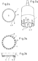
- FIGS. 2a, 2b, 3a, 3b . 4a and 4b illustrated objects are not inventive and show for clarity objects of the prior art.
- FIG. 2a, b show a simplified view of the bumper as a component 2 seen from the welding area 11 of the fixture 1, ie a sensor receiving element with only a circumferential raised projection 12 as a ring 4.
- the circumferential ring 4 is interrupted radially on the diameter in an inventive embodiment.
- the interruptions are identified by the reference numeral 8.
- the ring 4 or the circumferential rib forms a kind of crown drill, as in FIG. 2b is shown, on the one hand to create space for the weld metal or the melt and on the other to improve a kind of sawing effect for the penetration of possible dirt or the easy “digging" in the actual component surface.
- FIG. 3a shows a simplified view from below of the sensor receiving element as an attachment 1 with radial ribs 9, which can also be referred to as welding ribs.
- FIG. 3b shows trapezoidal welding ribs 9.
- FIG. 4a, b show a simplified view from below of the sensor receiving element with welding studs 13 instead of welding ribs.
Landscapes
- Engineering & Computer Science (AREA)
- Mechanical Engineering (AREA)
- Lining Or Joining Of Plastics Or The Like (AREA)
Description
- Die Erfindung betrifft ein Verfahren zum Verschweißen eines Anbauteils mit einem Bauteil, insbesondere für ein Kraftfahrzeug, mit dem an sich bekannten torsionalen Ultraschallschweißverfahren mit einer Sonotrode zur Übertragung der den Schweißvorgang erzeugenden Schwingungen auf das zu verschweißende Anbauteil, wobei das Anbauteil mit einer Ankopplungsfläche zur Ankopplung der Schwingungen der Sonotrode versehen wird und das Anbauteil auf dem zur Schweißfläche auf dem Bauteil gewandten Schweißbereich mit Kopplungselementen zur Ankopplung der von der Sonotrode induzierten Schwingungen versehen wird und dadurch beim Schweißvorgang die Kopplungselemente schmelzen und so das Anbauteil mit dem Bauteil verschweißen. Außerdem werden Anbauteile zur Verwendung mit diesem Verfahren vorgeschlagen.
- Eine etablierte Technik zum Verbinden von Bauteilen aus Kunststoff ist das Schweißen. Hierzu werden diverse Möglichkeiten zur Energieeinbringung genutzt. Zum Beispiel Reibschweißen oder Ultraschallschweißen.
- Speziell bei der Anwendung im automobilen Außenbereich liegen, aufgrund der Möglichkeiten, die die neuen Materialeigenschaften beim Spritzgießen bieten, die zurzeit gängigen Wandstärken bei der Verarbeitung im Bereich von >= 3,0 mm. Die hierbei standardmäßig zum Einsatz kommende Materialart ist, aufgrund des Preises, mit Talkum verstärktes PP.
- Aufgrund der dünnen Wandstärke sinken Kosten und Gewicht des Bauteils. Da jedoch speziell PP gegenüber anderen technischen Kunststoffen unter Last sehr kriechfähig ist und über ein geringes E-Modul verfügt, gleichzeitig aber die an die Bauteilverschweißung gestellten Forderungen von Haltekräften an den geschweißten Bauteilverbund von > 200N je Schweißstelle unverändert bleiben, ist es oft nicht möglich die Bauteile so zu verbinden, dass die optisch relevante Oberfläche fehlerfrei bleibt. Hierbei behindern zwei Einflussfaktoren eine abzeichnungsfreie Verschweißung:
- Die eingebrachte Energie zur Aufschmelzung und innigen Verbindung der Trennebene wirkt sich durch das Bauteil hindurch derart aus, das die Oberfläche in Folge des Schwindungsunterschieds beim Abkühlen des Bauteils deformiert und eine Fehlstelle ausbildet.
- Die beim Schweißen punktartig in den Bauteilverbund eingebrachten Kräfte führen an der Oberfläche, bei zu geringer Bauteildicke und E-Modul der Oberfläche, zu sichtbaren Deformationen. Die Oberfläche gibt unter der Last der eingebrachten Spannungen nach und bildet eine sichtbare Fehlstelle aus.
- Eine Entwicklung um diesen Effekt zu verhindern, ist das torsionale Ultraschallschweißen, wie es in der
EP 1 930 148 A1 und der noch unveröffentlichtenDE 10 2009 01 1273 A1 beschrieben ist. Dabei wird das unter der Sonotrode liegende obere Bauteil in rotatorische Schwingung im Frequenzbereich des Ultraschalls versetzt. Die Schwingung wird durch das obere Bauteil weitergegeben und direkt in der Trennebene zwischen oberen und unteren Bauteil in Wärme umgesetzt. Das obere Bauteil wird zwar durch seine innere Dämpfung erwärmt aber nicht aufgeschmolzen. Hierdurch reduziert sich zum einen die auf das untere Bauteil wirkende Hitze, zum anderen wird die wirksame Verbindungsfläche zur Krafteinleitung von punktartig in eine linien und/oder flächenartige Verbindung gewandelt. Als Resultat sind abzeichnungsfreie Verbindungen bei polyolefinen Werkstoffen auch unter 3,0 mm Wanddicke möglich. Die Entstehung von Fehlstellen konnte so verhindert werden. - In dieser Beschreibung bezeichnen die Begriffe oberes Bauteil und Anbauteil sowie unteres Bauteil und Bauteil die gleichen Gegenstände. Auf das Anbauteil bzw. auf das obere Bauteil wird die Sonotrode aufgesetzt, um das unter dem Anbauteil sich befindliche Bauteil mit dem Anbauteil zu verschweißen.
- Die als torsionales Schweißen bekannte Ultraschallschweißtechnik bedarf eines hohen Anpressdrucks. Speziell im Fall einer leichten Verschmutzung der Oberfläche durch vorangegangene Arbeitsschritte wird die benötigte Temperatur des Schweißgutes oft nicht erreicht, sondern dieses deformiert und eine innige Verbindung verhindert. Außerdem wird das verflüssigte Material durch den hohen Anpressdruck aus dem Bereich der Schweißstelle gedrückt. Eine kalte Schweißstelle mit schlechter Haftung ist das Resultat.
- Die
EP 1410988A1 beschreibt ein Verfahren zum Verschließen eines Behälters mittels Ultraschallwellen.
DieUS 2005/0028492A1 befasst sich mit einem Verfahren zur Herstellung eines Tonerbehälters und einem Tonerbehälter. - Die
WO 2006/128246A1 betrifft einen verschließbaren Behälter, und ein Verfahren zum Verschließen eines Behälters.
DieGB 2116667A
DieDE 19758075A1 betrifft Sensoraufnahmehülsen für Stoßfänger.
DieUS 2005/0104389A1 beschreibt ein Verfahren zum Fügen zweier Bauteile eines Kraftfahrzeuges.
DieJP H04201236A
Der Erfindung liegt die Aufgabe zugrunde, ein Verfahren nach dem Anspruch 1 anzugeben, mit dem die Menge und Verweildauer der Schmelze während des Schweißvorgangs an der Schweißfläche erhöht wird und dadurch lokal die benötigte Schmelzetemperatur und Einwirkdauer zur Erzeugung der benötigten Verbindungsqualität erreicht wird. Außerdem sollen Anbauteile angegeben werden, die durch geeignete konstruktive Maßnahmen an ihrem Schweißbereich das innige Verschweißen ermöglichen. Außerdem soll eine Verschweißung auch bei leichten Verschmutzungen möglich sein.
Erfindungsgemäß wird die Aufgabe bezüglich des Verfahrens dadurch gelöst, dass als Kopplungselemente sich im Wesentlichen senkrecht zum ringförmigen Schweißbereich erstreckende Auskragungen verwendet werden, die so angeordnet werden, dass die Schmelze im Wesentlichen auf der Schweißfläche bleibt. Die Auskragungen sind zwei koaxial angeordnete Ringe, die den ringförmigen Schweißbereich eingrenzen. Wie in Versuchen gezeigt wurde, ist ein Verschweißen von zwei Bauteilen in dem Moment gewährleistet, in dem sowohl der benötigte Anpressdruck zur Einkopplung des Ultraschalls gewährleistet wird, als auch verhindert wird, dass die Schmelze aus der Schweißfläche direkt weggedrückt wird. Die Auskragungen werden daher so angeordnet, dass ein Wegdrücken der Schmelze vermindert oder verhindert wird. - In einer Weiterbildung der Erfindung wird die Schmelze unter benachbarte Auskragungen gelenkt oder es werden zwei parallel entstehende Schmelzeflüsse gegeneinander gelenkt. Es kann auch ein entstehender Schmelzefluss gezielt unter benachbarte Auskragungen geleitet werden, die noch schmelzen werden. In diesem Fall spricht man von einer Opfer-Auskragung. Wenn zwei parallel entstehende Schmelzeflüsse gegeneinander gelenkt werden, bildet sich ein Reservoir an Schmelze.
- Nachfolgend werden erfindungsgemäße Anbauteile beschrieben, die durch geeignete konstruktive Maßnahmen an ihrem Schweißbereich das innige Verschweißen ermöglichen.
- Beschrieben werden Anbauteile mit zumindest einem für eine Verschweißung mit einem Bauteil vorgesehenen ringförmigen Schweißbereich, wobei die Verschweißung mit dem an sich bekannten torsionalen Ultraschallschweißverfahren erfolgen soll mit einer Sonotrode zur Übertragung der den Schweißvorgang erzeugenden Schwingungen auf das zu verschweißende Anbauteil, wobei das Anbauteil eine Ankopplungsfläche zur Ankopplung der Schwingungen der Sonotrode aufweist und das Anbauteil auf seinem zur vorgesehenen Schweißfläche auf dem Bauteil gewandten Schweißbereich mit Kopplungselementen zur Ankopplung der von der Sonotrode induzierten Schwingungen versehen ist, die beim Schweißvorgang schmelzen und so das Anbauteil mit dem Bauteil verschweißen.
- Erfindungsgemäß sind die Kopplungselemente im Wesentlichen senkrecht zum Schweißbereich sich erstreckende Auskragungen, nämlich zwei koaxial angeordnete Ringe, die den ringförmigen Schweißbereich eingrenzen. Die Schmelze, die sich innerhalb der koaxial angeordneten Ringe befindet, kann aufgrund der Ringe aus dem Schweißbereich nicht weggedrückt werden.
- In einer erfinderischen Ausgestaltung sind die Auskragungen Rippen oder Noppen.
- In einer Ausführungsform bilden die Auskragungen eine erhabene Kette mit Unterbrechungen. Diese erhabene Kette mit Unterbrechungen kann so auf dem Schweißbereich angeordnet werden, dass der Schmelzefluss im Bereich der Schweißfläche bleibt und nicht weggedrückt wird.
- Ergänzend zu dem eben Beschriebenen kann die Geometrie der Auskragungen bzw. der jeweiligen Rippengeometrie radial am Durchmesser unterbrochen werden um zum einen Platz für das Schweißgut zu schaffen und zum anderen eine Art Sägeeffekt für das Durchdringen möglicher Verschmutzungen bzw. das leichte "Eingraben" in die eigentliche Bauteiloberfläche zu verbessern. Dies ist bevorzugt anzuwenden bei Auskragungen, die einen Ring bilden und den Schweißbereich umgeben.
- Zur Lenkung des Schmelzeflusses können die Auskragungen im Querschnitt dreieckförmig, M-förmig, keilförmig, trapezförmig oder wellenförmig ausgebildet sein.
- Nachfolgend wird die Erfindung unter anderem anhand von Figuren näher erläutert.
- Beim torsionalen Ultraschallschweißverfahren (siehe
Figur 5 ) wird eine Sonotrode (in den Figuren nicht gezeigt) zur Übertragung der den Schweißvorgang erzeugenden Schwingungen verwendet, die auf das zu verschweißende Anbauteil 1 auf die Ankopplungsfläche 10 aufgesetzt wird. Das zu verschweißende Anbauteil 1 wird in dieser Beschreibung auch als oberes Teil bezeichnet und das Bauteil 2 mit dem das Anbauteil 1 verschweißt werden soll, wird auch als unteres Teil bezeichnet. Beim Schweißvorgang werden die Schwingungen der Sonotrode auf die Schweißfläche 3 übertragen und verschweißen so das Anbauteil 1 mit dem Bauteil 2. Sowohl das Anbauteil 1 als auch das Bauteil sind Kunststoffteile. Das Anbauteil 1 ist in allen hier gezeigten Figuren ein Halter, der an einen Stoßfänger als Bauteil 2 angeschweißt wird. Der Halter dient zur Aufnahme eines Ultraschallparksensors (nicht gezeigt). Das Anbauteil 1 weist hierzu eine Bohrung 5 zur Aufnahme des Ultraschallparksensors auf. Mit dem Pfeil 6 inFigur 5 sind die Schwingungen angedeutet, die von der Sonotrode beim Schweißvorgang erzeugt werden. - Bevorzugt werden das erfindungsgemäße Verfahren und die Anbauteile 1 im Automotivbereich verwendet und dort bevorzugt an Außen- oder Innenteilen aus Kunststoff. Eine bevorzugte Anwendungsform ist das Anschweißen von Anbauteilen 1 an sichtbare Außenteile des Kraftfahrzeugs. Zum Beispiel können mit diesem Verfahren Anbauteile 1 an zum Beispiel einen Stoßfänger oder einen Radkasten angeschweißt werden.
- Die Anbauteile 1 bzw. oberen Teile, werden erfindungsgemäß schon bei der Herstellung so ausgebildet, dass sie problemlos mit dem erfindungsgemäßen Verfahren an Bauteile 2, bzw. untere Teile angeschweißt werden können. Da diese Anpassung der oberen Teile sichtbar ist, kann beurteilt werden, ob diese für die Anwendung des erfindungsgemäßen Verfahrens vorbereitet wurden. Die in den
Figuren 1d und 1g dargestellten Gegenstände sind nicht erfindungsgemäß und zeigen zur Verdeutlichung Gegenstände des Standes der Technik.Figur 1d zeigt ein Sensoraufnahmeelement als Anbauteil 1 zur Aufnahme eines Sensors, welches mit einem Stoßfänger als Bauteil 2 mit dem torsionalen Ultraschallschweißverfahren verschweißt werden soll. Das Sensoraufnahmeelement bzw. Anbauteil 1 ist hier das obere Teil und der Stoßfänger als Bauteil 2 das untere Teil. Beim Schweißvorgang wird eine zylinderförmige Torsionssonotrode (nicht gezeigt) auf die Ankopplungsfläche 10 aufgesetzt. Die Schwingungen der Torsionssonotrode werden dadurch über die Ankopplungsfläche 10 auf das Sensoraufnahmeelement übertragen und durch das Sensoraufnahmeelement auf das untere Teil, den Stoßfänger übertragen und verschweißen so das obere Teil mit dem unteren Teil. Das obere und das untere Teil sind Kunststoffteile. - In den
Figuren 1a, 1b, 1c, 1e, 1f, 1g, 1h ist in verschiedenen Ausführungsformen der Schweißbereich 11 auf der Unterseite des Anbauteils 1 gezeigt, d.h. des Teils, welches auf dem Bauteil 2 (siehe auchFigur 5 ) aufsitzt.Figur 1 a zeigt zwei ringförmige Auskragungen 12, die jeweils einen Ring 4 bilden, die koaxial zueinander auf dem Schweißbereich 11 des Anbauteils 1 angeordnet sind. In dieser Ausführungsform sind die Ringe 4 im Querschnitt rechteckig ausgebildet und haben eine Spitze. Die Ringe 4 sitzen beim Schweißvorgang auf der Schweißfläche 3 auf dem Bauteil 2 auf und grenzen einen Schweißraum 7 ein.Figur 1 b zeigt ebenfalls zwei Ringe 4, die im Querschnitt jedoch dreiecksförmig ausgebildet sind und ebenfalls einen Schweißraum 7 eingrenzen. Der Schweißraum 7 dient beim Schweißvorgang als Reservoir oder Speicherraum für die Schmelze. Zwischen den Ringen 4 treffen sich die zwei Schmelzeströme, die durch das Aufschmelzen der beiden Ringe 4 erzeugt werden und können so nicht weggedrückt werden. -
Figur 1c zeigt zwei koaxiale Ringe 4, die im Querschnitt als gegeneinander gestellte Pyramiden ausgebildet sind. Diese bilden drei Schweißräume 7.Figur 1e zeigt auf dem Schweißbereich 11 auf der Unterseite des Anbauteils 1 drei ringförmige Rippen oder Ringe 4 als Auskragungen, die koaxial zueinander angeordnet sind. Hierdurch sind zwei Auffangräume, Speicherräume oder Schweißräume 7 gebildet zur Aufnahme der Schmelzeströme.Figur 1f zeigt zwei Ringe 4, die im Querschnitt über eine Kurve ineinander übergehen. Hier ist zwischen den Ringen 4 auch ein Auffangraum angeordnet.Figur 1 g zeigt eine im Schnitt rechteckförmige Rippe als Ring 4 undFigur 1h den Stand der Technik. - Die in den
Figuren 2a, 2b, 3a, 3b ,4a und 4b dargestellten Gegenstände sind nicht erfindungsgemäß und zeigen zur Verdeutlichung Gegenstände des Standes der Technik.Figur 2a, b zeigen eine vereinfachte Ansicht vom Stoßfänger als Bauteil 2 aus gesehen auf den Schweißbereich 11 des Anbauteils 1, d.h. eines Sensoraufnahmeelements mit nur einer umlaufenden erhabenen Auskragung 12 als Ring 4. Erfindungsgemäß ist in einer erfinderischen Ausgestaltung der umlaufende Ring 4 radial am Durchmesser unterbrochen. - Die Unterbrechungen sind mit dem Bezugszeichen 8 gekennzeichnet. Im Prinzip bildet der Ring 4 oder die umlaufende Rippe einen Art Kronenbohrer, wie er in
Figur 2b gezeigt ist, um zum einen Platz für das Schweißgut bzw. die Schmelze zu schaffen und zum anderen eine Art Sägeeffekt für das Durchdringen möglicher Verschmutzungen bzw. das leichte"Eingraben" in die eigentliche Bauteiloberfläche zu verbessern. -
Figur 3a zeigt eine vereinfachte Ansicht von unten auf das Sensoraufnahmeelement als Anbauteil 1 mit radialen Rippen 9, die auch als Schweißrippen bezeichnet werden können.Figur 3b zeigt trapezförmige Schweißrippen 9.Figur 4a, b zeigen eine vereinfachte Ansicht von unten auf das Sensoraufnahmeelement mit Schweißnoppen 13 anstatt Schweißrippen.
Claims (7)
- Verfahren zum Verschweißen eines Sensoraufnahmeelements (1) mit einem Stoßfänger (2), wobei sowohl das Sensoraufnahmeelement (1) als auch der Stoßfänger (2) Kunststoffteile für ein Kraftfahrzeug sind, mit dem an sich bekannten torsionalen Ultraschallschweißverfahren mit einer zylinderförmigen Torsionssonotrode zur Übertragung der den Schweißvorgang erzeugenden Schwingungen auf das zu verschweißende Sensoraufnahmeelement (1), wobei das Sensoraufnahmeelement (1) mit einer Ankopplungsfläche (10) zur Ankopplung der Schwingungen der zylinderförmigen Torsionssonotrode versehen wird und das Sensoraufnahmeelement (1) auf dem zur Schweißfläche (3) auf dem Stoßfänger (2) gewandten ringförmigen Schweißbereich (11) mit Kopplungselementen zur Ankopplung der von der zylinderförmigen Torsionssonotrode induzierten Schwingungen versehen wird und dadurch beim Schweißvorgang die Kopplungselemente schmelzen und so das Sensoraufnahmeelement (1) mit dem Stoßfänger (2) verschweißen, wobei als Kopplungselemente sich im Wesentlichen senkrecht zum Schweißbereich (11) erstreckende Auskragungen (12) verwendet werden, die so angeordnet werden, dass die Schmelze im Wesentlichen auf der Schweißfläche (3) bleibt, und wobei die Auskragungen (12) zwei koaxial angeordnete Ringe (4) sind, die den ringförmigen Schweißbereich (11) eingrenzen.
- Verfahren nach Anspruch 1, dadurch gekennzeichnet, dass die Schmelze unter benachbarte Auskragungen (12) gelenkt oder zwei parallel entstehende Schmelzflüsse gegeneinander gelenkt werden.
- Anbauteil (1) aus Kunststoff mit zumindest einem für eine Verschweißung mit einem Stoßfänger (2) aus Kunststoff vorgesehenen ringförmigen Schweißbereich (11), wobei die Verschweißung mit dem an sich bekannten torsionalen Ultraschallschweißverfahren erfolgen soll mit einer zylinderförmigen Torsionssonotrode zur Übertragung der den Schweißvorgang erzeugenden Schwingungen auf das zu verschweißende Anbauteil (1), wobei das Anbauteil (1) eine Ankopplungsfläche (10) zur Ankopplung der Schwingungen der zylinderförmigen Torsionssonotrode aufweist und das Anbauteil (1) auf seinem zur vorgesehenen Schweißfläche (3) auf dem Stoßfänger (2) gewandten Schweißbereich (11) mit Kopplungselementen zur Ankopplung der von der zylinderförmigen Torsionssonotrode induzierten Schwingungen versehen ist, die beim Schweißvorgang schmelzen und so das Anbauteil (1) mit dem Stoßfänger (2) verschweißen, zur Verwendung für ein Verfahren nach Anspruch 1 oder 2, wobei die Kopplungselemente im Wesentlichen senkrecht zum Schweißbereich sich erstreckende Auskragungen (12) sind, dadurch gekennzeichnet, dass das Anbauteil ein Sensoraufnahmeelement für ein Kraftfahrzeug ist, und die Auskragungen (12) zwei koaxial angeordnete Ringe (4) sind, die den ringförmigen Schweißbereich (11) eingrenzen.
- Anbauteil nach Anspruch 3, dadurch gekennzeichnet, dass die Auskragungen (12) Rippen oder Noppen sind.
- Anbauteil nach Anspruch 3 oder 4, dadurch gekennzeichnet, dass die Auskragungen (12) eine erhabene Kette mit Unterbrechungen bilden.
- Anbauteil nach einem der Ansprüche 3 bis 5, dadurch gekennzeichnet, dass die Ringe (4) radial am Durchmesser unterbrochen sind.
- Anbauteil nach einem der Ansprüche 3 bis 6, dadurch gekennzeichnet, dass die Auskragungen (12) im Querschnitt dreieckförmig, M-förmig, keilförmig, trapezförmig oder wellenförmig ausgebildet sind.
Priority Applications (1)
| Application Number | Priority Date | Filing Date | Title |
|---|---|---|---|
| PL10732340T PL2451629T3 (pl) | 2009-07-06 | 2010-07-06 | Element dołączany do łączenia z elementem konstrukcyjnym przy pomocy zgrzewania ultradźwiękowego skrętnego |
Applications Claiming Priority (3)
| Application Number | Priority Date | Filing Date | Title |
|---|---|---|---|
| DE102009031984 | 2009-07-06 | ||
| DE102009060444 | 2009-12-22 | ||
| PCT/EP2010/059611 WO2011003891A1 (de) | 2009-07-06 | 2010-07-06 | Anbauteil zur verbindung mit einem bauteil durch torsionales ultraschallschweissen |
Publications (2)
| Publication Number | Publication Date |
|---|---|
| EP2451629A1 EP2451629A1 (de) | 2012-05-16 |
| EP2451629B1 true EP2451629B1 (de) | 2018-06-20 |
Family
ID=42983371
Family Applications (1)
| Application Number | Title | Priority Date | Filing Date |
|---|---|---|---|
| EP10732340.4A Not-in-force EP2451629B1 (de) | 2009-07-06 | 2010-07-06 | Anbauteil zur verbindung mit einem bauteil durch torsionales ultraschallschweissen |
Country Status (7)
| Country | Link |
|---|---|
| US (1) | US8986478B2 (de) |
| EP (1) | EP2451629B1 (de) |
| CN (1) | CN102574328B (de) |
| DE (1) | DE102010026300A1 (de) |
| ES (1) | ES2687778T3 (de) |
| PL (1) | PL2451629T3 (de) |
| WO (1) | WO2011003891A1 (de) |
Families Citing this family (16)
| Publication number | Priority date | Publication date | Assignee | Title |
|---|---|---|---|---|
| WO2011101412A1 (de) * | 2010-02-18 | 2011-08-25 | Faurecia Exteriors Gmbh | Anpassung und individualisierung der oberflächenkontur zu verbindender körper, speziell beim torsionalen ultraschallschweissen |
| US20120087531A1 (en) * | 2010-10-07 | 2012-04-12 | Apple Inc. | Ultrasonically welded structures and methods for making the same |
| DE102013015452A1 (de) | 2013-09-18 | 2015-03-19 | Valeo Schalter Und Sensoren Gmbh | Verfahren zum Herstellen einer Magneteinheit für eine Sensoreinrichtung zum Erfassen einer einen Rotationszustand einer Lenkwelle eines Kraftfahrzeugs charakterisierenden Messgröße, Magneteinheit, Sensoreinrichtung und Kraftfahrzeug |
| CN203974666U (zh) * | 2014-08-06 | 2014-12-03 | 延锋彼欧汽车外饰系统有限公司 | 一种雾灯安装结构 |
| US9770863B2 (en) * | 2014-12-12 | 2017-09-26 | GM Global Technology Operations LLC | Systems and methods to reduce air pocket formation during welding |
| WO2017000998A1 (de) * | 2015-06-30 | 2017-01-05 | Telsonic Holding Ag | Vorrichtung zum verschweissen von bauteilen mittels ultraschalls durch torsionschwingungen |
| DE102016201073A1 (de) * | 2016-01-26 | 2017-07-27 | Robert Bosch Gmbh | Verfahren zum Befestigen einer Trägereinrichtung an einer Fahrzeugverkleidung eines Fahrzeugs |
| DE102016202307A1 (de) | 2016-02-16 | 2017-08-17 | Robert Bosch Gmbh | Halterung für einen Sensor |
| CN107009020A (zh) * | 2017-05-03 | 2017-08-04 | 广州市科普超声电子技术有限公司 | 一种超声波焊接头以及超声波焊接装置 |
| DE102017008170A1 (de) * | 2017-08-31 | 2019-02-28 | Webasto SE | Kunststoffbauteil mit daran verankertem Anbauteil |
| USD842152S1 (en) | 2017-10-12 | 2019-03-05 | Telsonic Holding Ag | Sensor holder |
| WO2019210936A1 (de) | 2018-05-01 | 2019-11-07 | Telsonic Holding Ag | Bauteil, verbundteil, schweisswerkzeug und verfahren zum verdrehschweissen |
| DE102018124779A1 (de) * | 2018-10-08 | 2020-04-09 | Ensinger Gmbh | Verfahren zur Herstellung eines Isolierprofils |
| EP3835035A1 (de) * | 2019-12-11 | 2021-06-16 | Telsonic Holding AG | Verfahren zum verbinden von werkstücken und zusammengesetzter gegenstand |
| CN111266722B (zh) * | 2019-12-24 | 2022-08-30 | 上海骄成超声波技术股份有限公司 | 一种超声波焊头和焊接装置 |
| DE102020114997A1 (de) * | 2020-06-05 | 2021-12-09 | Dräger Safety AG & Co. KGaA | Sieb für einen Atemkalkbehälter und Verfahren zum Herstellen eines Atemkalkbehälters |
Citations (1)
| Publication number | Priority date | Publication date | Assignee | Title |
|---|---|---|---|---|
| JPH04201236A (ja) * | 1990-11-29 | 1992-07-22 | Seidensha Denshi Kogyo Kk | プラスチックの伝達溶着法 |
Family Cites Families (10)
| Publication number | Priority date | Publication date | Assignee | Title |
|---|---|---|---|---|
| FR2523246A1 (fr) * | 1982-03-11 | 1983-09-16 | Dunlop Sa | Dispositifs a fluide sous pression, tels que verins, ressorts et/ou amortisseurs de chocs et/ou de vibrations |
| US5403415A (en) * | 1993-11-17 | 1995-04-04 | Abaxis, Inc. | Method and device for ultrasonic welding |
| DE19758075C2 (de) * | 1997-08-21 | 2003-05-08 | Itt Mfg Enterprises Inc | Mit dem Stoßfänger eines Kraftfahrzeugs verbundene Aufnahmehülse für Sensoren |
| DE60229948D1 (de) | 2001-03-12 | 2009-01-02 | Yakult Honsha Kk | Ultraschallwellendichtungsverfahren für behälter |
| US6802411B2 (en) * | 2002-10-03 | 2004-10-12 | Seagate Technology Llc | Dampening datum plate for disc drive component assembly |
| JP4323852B2 (ja) | 2003-04-11 | 2009-09-02 | キヤノン株式会社 | トナー補給容器の製造方法 |
| FR2859409B1 (fr) | 2003-09-08 | 2006-06-16 | Plastic Omnium Cie | Ensemble d'une piece d'aspect d'un vehicule automobile et d'une autre piece solidarisee a la piece d'aspect par fusion de matiere et procede d'assemblage de ces pieces |
| CN101233056B (zh) | 2005-06-03 | 2010-05-19 | 雷帕克亚洲太平洋有限公司 | 一种可密封容器,密封管,以及密封容器的方法 |
| EP1930148A1 (de) | 2006-12-07 | 2008-06-11 | Telsonic Holding AG | Verwendung einer Vorrichtung zum torsionalen Ultraschallschweissen |
| DE102010010327A1 (de) | 2009-03-05 | 2010-10-21 | Plastal Gmbh | Verfahren zur Befestigung eines Bauteils an ein Kunstoffteil eines Kraftfahrzeugs mit dem torsionalen Ultraschallschweißverfahren |
-
2010
- 2010-07-06 WO PCT/EP2010/059611 patent/WO2011003891A1/de not_active Ceased
- 2010-07-06 CN CN201080031000.8A patent/CN102574328B/zh not_active Expired - Fee Related
- 2010-07-06 PL PL10732340T patent/PL2451629T3/pl unknown
- 2010-07-06 DE DE102010026300A patent/DE102010026300A1/de not_active Ceased
- 2010-07-06 EP EP10732340.4A patent/EP2451629B1/de not_active Not-in-force
- 2010-07-06 ES ES10732340.4T patent/ES2687778T3/es active Active
- 2010-07-06 US US13/379,684 patent/US8986478B2/en not_active Expired - Fee Related
Patent Citations (1)
| Publication number | Priority date | Publication date | Assignee | Title |
|---|---|---|---|---|
| JPH04201236A (ja) * | 1990-11-29 | 1992-07-22 | Seidensha Denshi Kogyo Kk | プラスチックの伝達溶着法 |
Also Published As
| Publication number | Publication date |
|---|---|
| US8986478B2 (en) | 2015-03-24 |
| CN102574328A (zh) | 2012-07-11 |
| PL2451629T3 (pl) | 2019-03-29 |
| DE102010026300A1 (de) | 2011-01-20 |
| WO2011003891A1 (de) | 2011-01-13 |
| CN102574328B (zh) | 2016-03-16 |
| US20120155954A1 (en) | 2012-06-21 |
| ES2687778T3 (es) | 2018-10-29 |
| EP2451629A1 (de) | 2012-05-16 |
Similar Documents
| Publication | Publication Date | Title |
|---|---|---|
| WO2011003891A1 (de) | Anbauteil zur verbindung mit einem bauteil durch torsionales ultraschallschweissen | |
| DE112015000397B4 (de) | Verfahren zum Fügen eines Metallelements mit einem Harzelement | |
| DE69032332T2 (de) | Elektroschweissverbindung und deren Verwendung in einem Heisswasserverteiler | |
| DE102015120717B4 (de) | Verfahren und system zum fügen von werkstücken | |
| EP2403704B1 (de) | Verfahren zur befestigung eines bauteils an ein kunststoffteil eines kraftfahrzeugs mit dem torsionalen ultraschallschweissverfahren | |
| EP3096935B1 (de) | Verfahren zum fügen von faserverstärktem kunststoffmaterial | |
| DE102017112744A1 (de) | Verbinden von thermoplastischen Verbundstoffen durch Ultraschallschweißen | |
| DE102017107938A1 (de) | Reibniet zum Verbinden unterschiedlicher Materialien | |
| DE2159930B2 (de) | Verfahren zum dichten Verbinden eines Behältermantels aus thermoplastischem Kunststoff mit einem Boden- oder Deckelteil aus thermoplastischem Kunststoff mittels Ultraschall sowie hohlzylindrische Sonotrode zur Ausübung dieses Verfahrens | |
| EP1902811A1 (de) | Verbindung eines einen galvanischen Überzug aus Aluminium aufweisenden Befestigungselements aus Stahl mit einem flächigen Bauteil aus Aluminium | |
| DE102016204120A1 (de) | Harzbauteil | |
| DE102011116515B4 (de) | Ansaugkrümmerzusammenbau | |
| EP2536550B1 (de) | Anpassung und individualisierung der oberflächenkontur zu verbindender körper, speziell beim torsionalen ultraschallschweissen | |
| WO2007098869A1 (de) | Verbinden von faserverstärktem material mit einem spritzgussmaterial; bauteil nebst vorrichtung zur durchführung des verfahrens | |
| EP2246178B1 (de) | Anbauteil zur Verbindung mit einem Bauteil durch torsionales Ultraschallschweißen | |
| DE19719363B4 (de) | Kunstharzverbundanordnung | |
| WO2013014004A1 (de) | Verfahren zur herstellung von fahrwerkskomponenten für nutzfahrzeuge durch reibschweissen und entsprechende achseinheit | |
| DE102014110908A1 (de) | Thermoplastisches Fügesystem und -verfahren | |
| DE102012021210A1 (de) | Fügebauteil, Fügeverbundbauteil und Verfahren zu dessen Herstellung | |
| EP3271138A2 (de) | Induktionsverbindungsmuffe | |
| WO2009062560A1 (de) | Verbundbauteil und verfahren zur herstellung eines verbundbauteils | |
| DE102014226955B4 (de) | Anbauteil zur Verbindung mit einem Bauteil und Verfahren zum Befestigen des Anbauteils an demBauteil | |
| EP3600849B1 (de) | Anbauteil zum verbinden mit einem bauteil | |
| DE102013223166A1 (de) | Sonotrode zum Ultraschallschweißen, Ultraschallschweißanlage, Verfahren zum Ultraschallschweißen, sowie Schweißverbindung | |
| EP3554799B1 (de) | Kunststoffformteil für eine formteilanordnung, entsprechende formteilanordnung sowie verfahren zum herstellen einer formteilanordnung |
Legal Events
| Date | Code | Title | Description |
|---|---|---|---|
| PUAI | Public reference made under article 153(3) epc to a published international application that has entered the european phase |
Free format text: ORIGINAL CODE: 0009012 |
|
| 17P | Request for examination filed |
Effective date: 20120206 |
|
| AK | Designated contracting states |
Kind code of ref document: A1 Designated state(s): AL AT BE BG CH CY CZ DE DK EE ES FI FR GB GR HR HU IE IS IT LI LT LU LV MC MK MT NL NO PL PT RO SE SI SK SM TR |
|
| DAX | Request for extension of the european patent (deleted) | ||
| 17Q | First examination report despatched |
Effective date: 20140218 |
|
| TPAC | Observations filed by third parties |
Free format text: ORIGINAL CODE: EPIDOSNTIPA |
|
| GRAP | Despatch of communication of intention to grant a patent |
Free format text: ORIGINAL CODE: EPIDOSNIGR1 |
|
| INTG | Intention to grant announced |
Effective date: 20180104 |
|
| GRAS | Grant fee paid |
Free format text: ORIGINAL CODE: EPIDOSNIGR3 |
|
| GRAA | (expected) grant |
Free format text: ORIGINAL CODE: 0009210 |
|
| AK | Designated contracting states |
Kind code of ref document: B1 Designated state(s): AL AT BE BG CH CY CZ DE DK EE ES FI FR GB GR HR HU IE IS IT LI LT LU LV MC MK MT NL NO PL PT RO SE SI SK SM TR |
|
| REG | Reference to a national code |
Ref country code: GB Ref legal event code: FG4D Free format text: NOT ENGLISH |
|
| REG | Reference to a national code |
Ref country code: IE Ref legal event code: FG4D Free format text: LANGUAGE OF EP DOCUMENT: GERMAN |
|
| REG | Reference to a national code |
Ref country code: AT Ref legal event code: REF Ref document number: 1010271 Country of ref document: AT Kind code of ref document: T Effective date: 20180715 |
|
| REG | Reference to a national code |
Ref country code: DE Ref legal event code: R096 Ref document number: 502010015095 Country of ref document: DE |
|
| REG | Reference to a national code |
Ref country code: FR Ref legal event code: PLFP Year of fee payment: 9 |
|
| REG | Reference to a national code |
Ref country code: DE Ref legal event code: R082 Ref document number: 502010015095 Country of ref document: DE Representative=s name: MAIWALD PATENTANWALTS- UND RECHTSANWALTSGESELL, DE Ref country code: DE Ref legal event code: R081 Ref document number: 502010015095 Country of ref document: DE Owner name: PLASTIC OMNIUM AUTOMOTIVE EXTERIORS GMBH, DE Free format text: FORMER OWNER: FAURECIA EXTERIORS GMBH, 31655 STADTHAGEN, DE |
|
| RAP2 | Party data changed (patent owner data changed or rights of a patent transferred) |
Owner name: PLASTIC OMNIUM AUTOMOTIVE EXTERIORS GMBH |
|
| REG | Reference to a national code |
Ref country code: GB Ref legal event code: 732E Free format text: REGISTERED BETWEEN 20180906 AND 20180912 |
|
| REG | Reference to a national code |
Ref country code: NL Ref legal event code: MP Effective date: 20180620 |
|
| REG | Reference to a national code |
Ref country code: ES Ref legal event code: FG2A Ref document number: 2687778 Country of ref document: ES Kind code of ref document: T3 Effective date: 20181029 |
|
| PG25 | Lapsed in a contracting state [announced via postgrant information from national office to epo] |
Ref country code: FI Free format text: LAPSE BECAUSE OF FAILURE TO SUBMIT A TRANSLATION OF THE DESCRIPTION OR TO PAY THE FEE WITHIN THE PRESCRIBED TIME-LIMIT Effective date: 20180620 Ref country code: NO Free format text: LAPSE BECAUSE OF FAILURE TO SUBMIT A TRANSLATION OF THE DESCRIPTION OR TO PAY THE FEE WITHIN THE PRESCRIBED TIME-LIMIT Effective date: 20180920 Ref country code: LT Free format text: LAPSE BECAUSE OF FAILURE TO SUBMIT A TRANSLATION OF THE DESCRIPTION OR TO PAY THE FEE WITHIN THE PRESCRIBED TIME-LIMIT Effective date: 20180620 Ref country code: SE Free format text: LAPSE BECAUSE OF FAILURE TO SUBMIT A TRANSLATION OF THE DESCRIPTION OR TO PAY THE FEE WITHIN THE PRESCRIBED TIME-LIMIT Effective date: 20180620 Ref country code: BG Free format text: LAPSE BECAUSE OF FAILURE TO SUBMIT A TRANSLATION OF THE DESCRIPTION OR TO PAY THE FEE WITHIN THE PRESCRIBED TIME-LIMIT Effective date: 20180920 |
|
| REG | Reference to a national code |
Ref country code: LT Ref legal event code: MG4D |
|
| PG25 | Lapsed in a contracting state [announced via postgrant information from national office to epo] |
Ref country code: LV Free format text: LAPSE BECAUSE OF FAILURE TO SUBMIT A TRANSLATION OF THE DESCRIPTION OR TO PAY THE FEE WITHIN THE PRESCRIBED TIME-LIMIT Effective date: 20180620 Ref country code: GR Free format text: LAPSE BECAUSE OF FAILURE TO SUBMIT A TRANSLATION OF THE DESCRIPTION OR TO PAY THE FEE WITHIN THE PRESCRIBED TIME-LIMIT Effective date: 20180921 Ref country code: HR Free format text: LAPSE BECAUSE OF FAILURE TO SUBMIT A TRANSLATION OF THE DESCRIPTION OR TO PAY THE FEE WITHIN THE PRESCRIBED TIME-LIMIT Effective date: 20180620 |
|
| PG25 | Lapsed in a contracting state [announced via postgrant information from national office to epo] |
Ref country code: NL Free format text: LAPSE BECAUSE OF FAILURE TO SUBMIT A TRANSLATION OF THE DESCRIPTION OR TO PAY THE FEE WITHIN THE PRESCRIBED TIME-LIMIT Effective date: 20180620 |
|
| PG25 | Lapsed in a contracting state [announced via postgrant information from national office to epo] |
Ref country code: IS Free format text: LAPSE BECAUSE OF FAILURE TO SUBMIT A TRANSLATION OF THE DESCRIPTION OR TO PAY THE FEE WITHIN THE PRESCRIBED TIME-LIMIT Effective date: 20181020 Ref country code: EE Free format text: LAPSE BECAUSE OF FAILURE TO SUBMIT A TRANSLATION OF THE DESCRIPTION OR TO PAY THE FEE WITHIN THE PRESCRIBED TIME-LIMIT Effective date: 20180620 Ref country code: RO Free format text: LAPSE BECAUSE OF FAILURE TO SUBMIT A TRANSLATION OF THE DESCRIPTION OR TO PAY THE FEE WITHIN THE PRESCRIBED TIME-LIMIT Effective date: 20180620 |
|
| REG | Reference to a national code |
Ref country code: SK Ref legal event code: T3 Ref document number: E 28736 Country of ref document: SK |
|
| PG25 | Lapsed in a contracting state [announced via postgrant information from national office to epo] |
Ref country code: SM Free format text: LAPSE BECAUSE OF FAILURE TO SUBMIT A TRANSLATION OF THE DESCRIPTION OR TO PAY THE FEE WITHIN THE PRESCRIBED TIME-LIMIT Effective date: 20180620 Ref country code: IT Free format text: LAPSE BECAUSE OF FAILURE TO SUBMIT A TRANSLATION OF THE DESCRIPTION OR TO PAY THE FEE WITHIN THE PRESCRIBED TIME-LIMIT Effective date: 20180620 |
|
| REG | Reference to a national code |
Ref country code: CH Ref legal event code: PL |
|
| REG | Reference to a national code |
Ref country code: DE Ref legal event code: R097 Ref document number: 502010015095 Country of ref document: DE |
|
| PG25 | Lapsed in a contracting state [announced via postgrant information from national office to epo] |
Ref country code: LU Free format text: LAPSE BECAUSE OF NON-PAYMENT OF DUE FEES Effective date: 20180706 Ref country code: MC Free format text: LAPSE BECAUSE OF FAILURE TO SUBMIT A TRANSLATION OF THE DESCRIPTION OR TO PAY THE FEE WITHIN THE PRESCRIBED TIME-LIMIT Effective date: 20180620 |
|
| REG | Reference to a national code |
Ref country code: BE Ref legal event code: MM Effective date: 20180731 |
|
| REG | Reference to a national code |
Ref country code: IE Ref legal event code: MM4A |
|
| PLBE | No opposition filed within time limit |
Free format text: ORIGINAL CODE: 0009261 |
|
| STAA | Information on the status of an ep patent application or granted ep patent |
Free format text: STATUS: NO OPPOSITION FILED WITHIN TIME LIMIT |
|
| PG25 | Lapsed in a contracting state [announced via postgrant information from national office to epo] |
Ref country code: IE Free format text: LAPSE BECAUSE OF NON-PAYMENT OF DUE FEES Effective date: 20180706 Ref country code: CH Free format text: LAPSE BECAUSE OF NON-PAYMENT OF DUE FEES Effective date: 20180731 Ref country code: LI Free format text: LAPSE BECAUSE OF NON-PAYMENT OF DUE FEES Effective date: 20180731 |
|
| 26N | No opposition filed |
Effective date: 20190321 |
|
| PG25 | Lapsed in a contracting state [announced via postgrant information from national office to epo] |
Ref country code: DK Free format text: LAPSE BECAUSE OF FAILURE TO SUBMIT A TRANSLATION OF THE DESCRIPTION OR TO PAY THE FEE WITHIN THE PRESCRIBED TIME-LIMIT Effective date: 20180620 Ref country code: BE Free format text: LAPSE BECAUSE OF NON-PAYMENT OF DUE FEES Effective date: 20180731 |
|
| PG25 | Lapsed in a contracting state [announced via postgrant information from national office to epo] |
Ref country code: SI Free format text: LAPSE BECAUSE OF FAILURE TO SUBMIT A TRANSLATION OF THE DESCRIPTION OR TO PAY THE FEE WITHIN THE PRESCRIBED TIME-LIMIT Effective date: 20180620 |
|
| REG | Reference to a national code |
Ref country code: AT Ref legal event code: MM01 Ref document number: 1010271 Country of ref document: AT Kind code of ref document: T Effective date: 20180706 |
|
| PGFP | Annual fee paid to national office [announced via postgrant information from national office to epo] |
Ref country code: ES Payment date: 20190822 Year of fee payment: 10 Ref country code: CZ Payment date: 20190813 Year of fee payment: 10 Ref country code: FR Payment date: 20190730 Year of fee payment: 10 Ref country code: SK Payment date: 20190812 Year of fee payment: 10 Ref country code: DE Payment date: 20190730 Year of fee payment: 10 Ref country code: TR Payment date: 20190812 Year of fee payment: 10 |
|
| PG25 | Lapsed in a contracting state [announced via postgrant information from national office to epo] |
Ref country code: AL Free format text: LAPSE BECAUSE OF FAILURE TO SUBMIT A TRANSLATION OF THE DESCRIPTION OR TO PAY THE FEE WITHIN THE PRESCRIBED TIME-LIMIT Effective date: 20180620 |
|
| PGFP | Annual fee paid to national office [announced via postgrant information from national office to epo] |
Ref country code: PL Payment date: 20190814 Year of fee payment: 10 |
|
| PG25 | Lapsed in a contracting state [announced via postgrant information from national office to epo] |
Ref country code: AT Free format text: LAPSE BECAUSE OF NON-PAYMENT OF DUE FEES Effective date: 20180706 |
|
| PGFP | Annual fee paid to national office [announced via postgrant information from national office to epo] |
Ref country code: GB Payment date: 20190730 Year of fee payment: 10 |
|
| PG25 | Lapsed in a contracting state [announced via postgrant information from national office to epo] |
Ref country code: MT Free format text: LAPSE BECAUSE OF FAILURE TO SUBMIT A TRANSLATION OF THE DESCRIPTION OR TO PAY THE FEE WITHIN THE PRESCRIBED TIME-LIMIT Effective date: 20180620 |
|
| PG25 | Lapsed in a contracting state [announced via postgrant information from national office to epo] |
Ref country code: PT Free format text: LAPSE BECAUSE OF FAILURE TO SUBMIT A TRANSLATION OF THE DESCRIPTION OR TO PAY THE FEE WITHIN THE PRESCRIBED TIME-LIMIT Effective date: 20180620 Ref country code: HU Free format text: LAPSE BECAUSE OF FAILURE TO SUBMIT A TRANSLATION OF THE DESCRIPTION OR TO PAY THE FEE WITHIN THE PRESCRIBED TIME-LIMIT; INVALID AB INITIO Effective date: 20100706 |
|
| PG25 | Lapsed in a contracting state [announced via postgrant information from national office to epo] |
Ref country code: MK Free format text: LAPSE BECAUSE OF NON-PAYMENT OF DUE FEES Effective date: 20180620 Ref country code: CY Free format text: LAPSE BECAUSE OF FAILURE TO SUBMIT A TRANSLATION OF THE DESCRIPTION OR TO PAY THE FEE WITHIN THE PRESCRIBED TIME-LIMIT Effective date: 20180620 |
|
| PG25 | Lapsed in a contracting state [announced via postgrant information from national office to epo] |
Ref country code: CZ Free format text: LAPSE BECAUSE OF NON-PAYMENT OF DUE FEES Effective date: 20200706 |
|
| REG | Reference to a national code |
Ref country code: DE Ref legal event code: R119 Ref document number: 502010015095 Country of ref document: DE |
|
| REG | Reference to a national code |
Ref country code: SK Ref legal event code: MM4A Ref document number: E 28736 Country of ref document: SK Effective date: 20200706 |
|
| GBPC | Gb: european patent ceased through non-payment of renewal fee |
Effective date: 20200706 |
|
| PG25 | Lapsed in a contracting state [announced via postgrant information from national office to epo] |
Ref country code: FR Free format text: LAPSE BECAUSE OF NON-PAYMENT OF DUE FEES Effective date: 20200731 Ref country code: GB Free format text: LAPSE BECAUSE OF NON-PAYMENT OF DUE FEES Effective date: 20200706 |
|
| PG25 | Lapsed in a contracting state [announced via postgrant information from national office to epo] |
Ref country code: DE Free format text: LAPSE BECAUSE OF NON-PAYMENT OF DUE FEES Effective date: 20210202 |
|
| PG25 | Lapsed in a contracting state [announced via postgrant information from national office to epo] |
Ref country code: SK Free format text: LAPSE BECAUSE OF NON-PAYMENT OF DUE FEES Effective date: 20200706 |
|
| REG | Reference to a national code |
Ref country code: ES Ref legal event code: FD2A Effective date: 20211202 |
|
| PG25 | Lapsed in a contracting state [announced via postgrant information from national office to epo] |
Ref country code: ES Free format text: LAPSE BECAUSE OF NON-PAYMENT OF DUE FEES Effective date: 20200707 |
|
| PG25 | Lapsed in a contracting state [announced via postgrant information from national office to epo] |
Ref country code: TR Free format text: LAPSE BECAUSE OF NON-PAYMENT OF DUE FEES Effective date: 20200706 |
|
| PG25 | Lapsed in a contracting state [announced via postgrant information from national office to epo] |
Ref country code: PL Free format text: LAPSE BECAUSE OF NON-PAYMENT OF DUE FEES Effective date: 20200706 |