EP2450207B2 - Device for arranging sensors for electrical actuation of a motor vehicle hatch - Google Patents
Device for arranging sensors for electrical actuation of a motor vehicle hatch Download PDFInfo
- Publication number
- EP2450207B2 EP2450207B2 EP12153333.5A EP12153333A EP2450207B2 EP 2450207 B2 EP2450207 B2 EP 2450207B2 EP 12153333 A EP12153333 A EP 12153333A EP 2450207 B2 EP2450207 B2 EP 2450207B2
- Authority
- EP
- European Patent Office
- Prior art keywords
- sensor
- bumper
- vehicle
- designed
- fact
- Prior art date
- Legal status (The legal status is an assumption and is not a legal conclusion. Google has not performed a legal analysis and makes no representation as to the accuracy of the status listed.)
- Active
Links
Images
Classifications
-
- B—PERFORMING OPERATIONS; TRANSPORTING
- B60—VEHICLES IN GENERAL
- B60J—WINDOWS, WINDSCREENS, NON-FIXED ROOFS, DOORS, OR SIMILAR DEVICES FOR VEHICLES; REMOVABLE EXTERNAL PROTECTIVE COVERINGS SPECIALLY ADAPTED FOR VEHICLES
- B60J5/00—Doors
- B60J5/10—Doors arranged at the vehicle rear
- B60J5/101—Doors arranged at the vehicle rear for non-load transporting vehicles, i.e. family cars including vans
-
- E—FIXED CONSTRUCTIONS
- E05—LOCKS; KEYS; WINDOW OR DOOR FITTINGS; SAFES
- E05F—DEVICES FOR MOVING WINGS INTO OPEN OR CLOSED POSITION; CHECKS FOR WINGS; WING FITTINGS NOT OTHERWISE PROVIDED FOR, CONCERNED WITH THE FUNCTIONING OF THE WING
- E05F15/00—Power-operated mechanisms for wings
- E05F15/70—Power-operated mechanisms for wings with automatic actuation
- E05F15/73—Power-operated mechanisms for wings with automatic actuation responsive to movement or presence of persons or objects
-
- E—FIXED CONSTRUCTIONS
- E05—LOCKS; KEYS; WINDOW OR DOOR FITTINGS; SAFES
- E05Y—INDEXING SCHEME RELATING TO HINGES OR OTHER SUSPENSION DEVICES FOR DOORS, WINDOWS OR WINGS AND DEVICES FOR MOVING WINGS INTO OPEN OR CLOSED POSITION, CHECKS FOR WINGS AND WING FITTINGS NOT OTHERWISE PROVIDED FOR, CONCERNED WITH THE FUNCTIONING OF THE WING
- E05Y2400/00—Electronic control; Power supply; Power or signal transmission; User interfaces
- E05Y2400/80—User interfaces
- E05Y2400/85—User input means
- E05Y2400/852—Sensors
- E05Y2400/856—Actuation thereof
- E05Y2400/858—Actuation thereof by body parts
-
- E—FIXED CONSTRUCTIONS
- E05—LOCKS; KEYS; WINDOW OR DOOR FITTINGS; SAFES
- E05Y—INDEXING SCHEME RELATING TO HINGES OR OTHER SUSPENSION DEVICES FOR DOORS, WINDOWS OR WINGS AND DEVICES FOR MOVING WINGS INTO OPEN OR CLOSED POSITION, CHECKS FOR WINGS AND WING FITTINGS NOT OTHERWISE PROVIDED FOR, CONCERNED WITH THE FUNCTIONING OF THE WING
- E05Y2900/00—Application of doors, windows, wings or fittings thereof
- E05Y2900/50—Application of doors, windows, wings or fittings thereof for vehicles
- E05Y2900/53—Application of doors, windows, wings or fittings thereof for vehicles characterised by the type of wing
- E05Y2900/546—Tailgates
Definitions
- the invention is directed to an arrangement of a sensor device with at least one sensor for contactless actuation of at least one movable part of a motor vehicle, in particular a flap of a motor vehicle, the sensor being arranged on at least one carrier body on the motor vehicle in order to detect an object in at least one to enable a detection area adjacent to the motor vehicle, so that the operation of the tailgate can be activated via the detection.
- a carrier body can be provided in the motor vehicle, which can be used as a basic component for any motor vehicle and can fulfill a function in the motor vehicle either without a sensor device or with a sensor device or at least be present in the motor vehicle.
- a decision can be made at a very late stage of assembly of the motor vehicle as to whether or not a sensor device should be provided as a further feature of the motor vehicle, since the sensor device can be installed in the motor vehicle or not without having to make a decision about the use of additional components.
- the senor can have an elongated, preferably tube-like extension and preferably have a flexibility which is designed in such a way that the sensor can be used by means of a manually insertable elastic deformation between the fastening tab and the counterholders, which are preferably present in duplicate. If two counter-holders are arranged opposite the fastening tab in the direction of extension of the sensor, three form-fitting elements are created, so that the two counter-holders face a single fastening tab. If the flexible sensor is bent in such a way that it can be inserted between the fastening tab and the two counterholders, the flexible sensor relaxes again into an elongated, straight shape. Consequently, a form-fitting connection of the sensor between the counter-holders and the fastening tab is created, so that it is not possible to release the sensor from the form-fitting elements without another elastic deformation of the sensor.
- this can be designed as a fastening dome which has a receiving pocket to accommodate the sensor.
- the fastening dome can be designed for the positive arrangement of a clip, which is designed as a counter element to the clamping arrangement of the sensor between the receiving pocket and the clip.
- the receiving cross section formed between the receiving pocket of the fastening dome and the clip can correspond to the cross section of the sensor and in particular the cross section of the plastic body, which represents the supporting, structure-forming part of the sensor.
- several fastening domes can be connected in one piece to the carrier body, so that the fastening domes are also formed directly in the injection molding process for producing the carrier body.
- the fastening domes can extend out of the extension plane of the carrier body in order to arrange the sensor at a certain distance from the basic structure of the carrier body.
Description
Die Erfindung richtet sich auf eine Anordnung einer Sensoreinrichtung mit wenigstens einem Sensor für eine berührungslose Betätigung wenigstens eines beweglichen Teils eines Kraftfahrzeugs, insbesondere einer Klappe eines Kraftfahrzeugs, wobei der Sensor an wenigstens einem Trägerkörper am Kraftfahrzeug angeordnet ist, um eine Detektion eines Objektes in wenigstens einem an das Kraftfahrzeug angrenzenden Detektionsbereich zu ermöglichen, so dass über die Detektion die Betätigung der Heckklappe aktivierbar ist.The invention is directed to an arrangement of a sensor device with at least one sensor for contactless actuation of at least one movable part of a motor vehicle, in particular a flap of a motor vehicle, the sensor being arranged on at least one carrier body on the motor vehicle in order to detect an object in at least one to enable a detection area adjacent to the motor vehicle, so that the operation of the tailgate can be activated via the detection.
Zur berührungslosen Betätigung von beweglichen Teilen eines Kraftfahrzeugs sind Sensoreinrichtungen bekannt, die das Vorhandensein und insbesondere die Bewegung einer Person sensieren, um darin den Wunsch zur Öffnung des beweglichen Teils des Kraftfahrzeugs zu erkennen. Das bewegliche Teil des Kraftfahrzeugs kann eine Klappe und insbesondere eine Heckklappe des Kraftfahrzeugs betreffen, wobei auch bewegliche Fensterelemente bekannt sind, wie etwa eine in einer Heckklappe bewegbare Heckscheibe, die dann durch eine gattungsbildende Sensoreinrichtung vorteilhaft geöffnet oder geschlossen werden kann, wenn eine manuelle Betätigung der Heckklappe nicht oder nur erschwert möglich ist. Im Folgenden wird das bewegliche Teil vereinfachend als Klappe bezeichnet.For the non-contact operation of moving parts of a motor vehicle, sensor devices are known which sense the presence and in particular the movement of a person in order to detect the desire to open the moving part of the motor vehicle. The movable part of the motor vehicle can relate to a flap and in particular a tailgate of the motor vehicle, with movable window elements also being known, such as a rear window that can be moved in a tailgate, which can then be advantageously opened or closed by a generic sensor device when manual actuation of the Tailgate is not possible or only possible with difficulty. In the following, the movable part is simply referred to as a flap.
Das durch die Sensoreinrichtung detektierte Objekt kann eine Person sein, die sich dem Kraftfahrzeug in der Absicht nähert, die Heckklappe zu öffnen. Die Betätigung der Heckklappe beschreibt dabei sowohl einen Öffnungsvorgang, beispielsweise wenn die Person einen Gegenstand beidhändig in den Kofferraum einlegen möchte oder die Betätigung der Heckklappe betrifft einen Schließvorgang der Heckklappe, wenn die Person beidhändig einen Gegenstand aus dem Kofferraum entnommen hat, um anschließend die Heckklappe zu schließen.The object detected by the sensor device may be a person who approaches the motor vehicle with the intention of opening the tailgate. The operation of the tailgate describes both an opening process, for example when the person wants to insert an object into the trunk with both hands, or the operation of the tailgate refers to a closing process of the tailgate, when the person has removed an object from the trunk with both hands in order to then close the tailgate close.
Die Sensoreinrichtung umfasst dabei wenigstens einen Sensor, der über einen Trägerkörper am Kraftfahrzeug angeordnet ist. Die Sensoren zur Heckklappenbetätigung sind gewöhnlich innenseitig im Stoßfänger angebracht, so dass der Trägerkörper durch den Stoßfänger selbst gebildet ist. Dabei ist bekannt, die Sensoren innenseitig auf der Oberfläche des Stoßfängers aufzukleben oder zu laminieren, wobei die Sensoren als kapazitiv wirkende Elektroden drahtartig oder folienartig ausgebildet sind. Dabei werden die Drähte oder Folien der durch Elektroden gebildeten Sensoren wenigstens über einen Teil oder bevorzugt über der gesamten Breite des Stoßfängers des Kraftfahrzeugs angebracht. Folglich ist eine Betätigung der Heckklappe des Kraftfahrzeugs aus verschiedenen Bereichen in der näheren Umgebung des Hecks des Kraftfahrzeugs möglich. Damit sind die Sensoren Bestandteil des hinteren Stoßfängers, die innenseitig im Stoßfänger aufgeklebt oder mit Befestigungsmitteln am Stoßfänger befestigt sind. Insbesondere ist bekannt, die Sensoren bereits im Kunststoff-Spritzgussprozess zur Herstellung des Stoßfängers einzusetzen, um ein einteiliges Bauteil mit umspritzten Sensoren zu erhalten.The sensor device comprises at least one sensor which is arranged on the motor vehicle via a carrier body. The sensors for tailgate operation are usually mounted on the inside of the bumper, so that the carrier body is formed by the bumper itself. It is known to glue or laminate the sensors on the inside of the surface of the bumper, with the sensors being designed as capacitive electrodes in a wire-like or film-like manner. The wires or foils of the sensors formed by electrodes are attached over at least part or preferably over the entire width of the bumper of the motor vehicle. Consequently, the tailgate of the motor vehicle can be operated from various areas in the immediate vicinity of the rear of the motor vehicle. The sensors are therefore part of the rear bumper and are glued to the inside of the bumper or attached to the bumper with fasteners. In particular, it is known to use the sensors in the plastic injection molding process for producing the bumper in order to obtain a one-piece component with overmolded sensors.
Ebenfalls ist in der Schrift
Daraus ergibt sich jedoch der Nachteil, dass wesentliche Komponenten des Kraftfahrzeugs, beispielsweise die hintere Stoßstange, unterschieden werden müssen in Bauteile, die die Sensoreinrichtung aufweisen, und Bauteile, die ohne die Sensoreinrichtung ausgeführt sind.However, this results in the disadvantage that essential components of the motor vehicle, for example the rear bumper, have to be differentiated into components that have the sensor device and components that are designed without the sensor device.
Folglich ist eine Verringerung der Variantenvielfalt einzelner Fahrzeugbestandteile wünschenswert.Consequently, a reduction in the variety of variants of individual vehicle components is desirable.
Es ist daher die Aufgabe der vorliegenden Erfindung, eine Anordnung einer Sensoreinrichtung zu schaffen, die eine vereinfachte Anordnung der Sensoren der Sensoreinrichtung im Kraftfahrzeug ermöglicht. Ferner ist es die Aufgabe der vorliegenden Erfindung, eine erhöhte organisatorische Flexibilität der Anordnung des Sensors für eine Sensoreinrichtung im Kraftfahrzeug zu schaffen.It is therefore the object of the present invention to create an arrangement of a sensor device which enables a simplified arrangement of the sensors of the sensor device in the motor vehicle. Furthermore, it is the object of the present invention to create increased organizational flexibility in the arrangement of the sensor for a sensor device in the motor vehicle.
Diese Aufgabe wird ausgehend von einer Anordnung einer Sensoreinrichtung gemäß dem Oberbegriff des Anspruchs 1 in Verbindung mit den kennzeichnenden Merkmalen gelöst. Vorteilhafte Weiterbildungen der Erfindung sind in den abhängigen Ansprüchen angegeben.This task is solved based on an arrangement of a sensor device according to the preamble of claim 1 in conjunction with the characterizing features. Advantageous developments of the invention are specified in the dependent claims.
Die Erfindung schließt die technische Lehre ein, dass der Sensor formschlüssig und/oder kraftschlüssig am Trägerkörper angeordnet ist. Damit wird der Vorteil erreicht, dass eine vereinfachte Anordnung des oder der Sensoren am Trägerkörper ermöglicht ist. Eine formschlüssige und/oder kraftschlüssige Anordnung des Sensors am Trägerkörper betrifft dabei jede Form der Anordnung, die nicht auf einer stoffschlüssigen Verbindung zwischen dem Sensor und dem Trägerkörper beruht und die keine Verwendung weiterer Befestigungselemente wie Schrauben, Nieten oder dergleichen erfordert.The invention includes the technical teaching that the sensor is arranged on the carrier body in a form-fitting and/or force-fitting manner. This achieves the advantage that a simplified arrangement of the sensor or sensors on the carrier body is possible. A positive and/or non-positive arrangement of the sensor on the carrier body refers to any form of arrangement that is not based on a material connection between the sensor and the carrier body and that does not require the use of further fastening elements such as screws, rivets or the like.
Vorzugsweise betrifft die vorliegende formschlüssige Anordnung des Sensors am Trägerkörper eine Clips- oder Schnappverbindung, die gemäß einem weiteren Vorteil sogar wieder lösbar sein kann. Der Trägerkörper kann am Kraftfahrzeug angeordnet werden, wobei der Trägerkörper auch Bestandteil des Kraftfahrzeugs sein kann. Eine Anordnung "am" Kraftfahrzeug umfasst dabei auch eine Anordnung "im" Kraftfahrzeug, etwa innenseitig hinter einem hinteren Stoßfänger.Preferably, the present positive arrangement of the sensor on the carrier body relates to a clip or snap connection, which according to a further advantage can even be detachable again. The carrier body can be arranged on the motor vehicle, whereby the carrier body can also be part of the motor vehicle. An arrangement “on” the motor vehicle also includes an arrangement “in” the motor vehicle, for example on the inside behind a rear bumper.
Folglich kann ein Trägerkörper im Kraftfahrzeug vorgesehen sein, der als Basisbauteil für jedes Kraftfahrzeug einsetzbar ist, und sowohl ohne eine Sensoreinrichtung als auch mit einer Sensoreinrichtung eine Funktion im Kraftfahrzeug erfüllen oder wenigstens im Kraftfahrzeug vorhanden sein kann. Gemäß eines weiteren Vorteils kann in einem sehr späten Stadium der Montage des Kraftfahrzeugs entschieden werden, ob eine Sensoreinrichtung als weiteres Merkmal des Kraftfahrzeugs vorgesehen sein soll oder nicht, da die Sensoreinrichtung wahlweise im Kraftfahrzeug eingebracht werden kann oder nicht, ohne eine Entscheidung über die Verwendung weiterer Bauteile treffen zu müssen.Consequently, a carrier body can be provided in the motor vehicle, which can be used as a basic component for any motor vehicle and can fulfill a function in the motor vehicle either without a sensor device or with a sensor device or at least be present in the motor vehicle. According to a further advantage, a decision can be made at a very late stage of assembly of the motor vehicle as to whether or not a sensor device should be provided as a further feature of the motor vehicle, since the sensor device can be installed in the motor vehicle or not without having to make a decision about the use of additional components.
Gemäß einer vorteilhaften Ausführungsform des Trägerkörpers kann dieser als einzeln handhabbares Trägermodul derart ausgeführt sein, dass das Trägermodul als im Wesentlichen vollständige Funktionseinheit in und/oder am Kraftfahrzeug befestigbar ist. Das Trägermodul kann dabei auf einem Aufnahmekörper basieren, an dem weitere Funktionseinheiten wie wenigstens ein Sensor angebracht werden können. Folglich kann das Trägermodul nur dann in einem Kraftfahrzeug montiert werden, wenn auch eine Sensoranordnung zur berührungslosen Betätigung einer Klappe eines Kraftfahrzeugs gewünscht ist. Unterbleibt dieses Merkmal an einem Kraftfahrzeug, so kann die Anordnung des Moduls als vollständige Funktionseinheit im Kraftfahrzeug unterbleiben.According to an advantageous embodiment of the carrier body, it can be designed as an individually manageable carrier module in such a way that the carrier module can be fastened as a substantially complete functional unit in and/or on the motor vehicle. The carrier module can be based on a receiving body to which further functional units such as at least one sensor can be attached. Consequently, the carrier module can only be mounted in a motor vehicle if a sensor arrangement for contactless actuation of a flap of a motor vehicle is also desired. If this feature is not present on a motor vehicle, the module cannot be arranged as a complete functional unit in the motor vehicle.
Hingegen kann das Kraftfahrzeug einen Stoßfänger und/oder ein Strukturbauteil aufweisen, wobei der Trägerkörper durch den Stoßfänger bzw. durch das Strukturbauteil selbst gebildet werden kann. Folglich kann der Stoßfänger und/oder das Strukturbauteil mit den jeweiligen Funktionseinheiten der Sensoreinrichtung konfektioniert werden, um diesen oder dieses anschließend am Kraftfahrzeug zu montieren. Im Ergebnis ist kein separater Trägerkörper notwendig, sofern der Trägerkörper durch ein Bauteil gebildet wird, das ohnehin in oder am Fahrzeug vorhanden ist.On the other hand, the motor vehicle can have a bumper and/or a structural component, wherein the carrier body can be formed by the bumper or by the structural component itself. Consequently, the bumper and/or the structural component can be assembled with the respective functional units of the sensor device in order to subsequently mount it on the motor vehicle. As a result, no separate carrier body is necessary as long as the carrier body is formed by a component that is already present in or on the vehicle.
Die Sensoren können vorzugsweise als kapazitiv wirkende Sensoren ausgeführt werden, so dass diese Elektroden besitzen bzw. bilden, auf denen durch die Elektrikeinheit eine gewisse Ladung aufrecht erhalten wird. Ändert sich die kapazitive Kopplung zwischen den Elektroden und dem Außenbereich des Kraftfahrzeugs, beispielsweise indem sich eine Person in den Detektionsbereich der Sensoren hineinbewegt, so ändert sich durch eine Änderung der Ladung auf den Elektroden, was durch die Elektrikeinheit messbar wird. Insbesondere kann die Elektrikeinheit eine Referenzladung aufweisen, so dass der Abgleich zwischen der Referenzladung, beispielsweise in Form eines Kondensators in der Elektrikeinheit, und den Elektroden eine messbare Größe des Vorhandenseins eines Objektes im Detektionsbereich des wenigstens einen Sensors bildet. Insbesondere kann eine Akkumulation der Ladung im Referenzkondensator innerhalb der Elektrikeinheit erfolgen, so dass die aufsummierte Ladung durch die Elektrikeinheit in ein Ausgangssignal umgewandelt werden kann, auf Basis dessen die Klappe des Kraftfahrzeugs geöffnet oder geschlossen wird.The sensors can preferably be designed as capacitive sensors, so that they have or form electrodes on which a certain charge is maintained by the electrical unit. If the capacitive coupling between the electrodes and the outside area of the motor vehicle changes, for example when a person moves into the detection range of the sensors, a change in the charge on the electrodes changes what can be measured by the electrical unit. In particular, the electrical unit can have a reference charge, so that the comparison between the reference charge, for example in the form of a capacitor in the electrical unit, and the electrodes forms a measurable quantity of the presence of an object in the detection range of the at least one sensor. In particular, the charge can accumulate in the reference capacitor within the electrical unit, so that the accumulated charge can be converted by the electrical unit into an output signal, on the basis of which the flap of the motor vehicle is opened or closed.
Im Ergebnis ist es hinreichend, die Sensoren innerhalb, am oder durch den Trägerkörper unabgeschirmt im Fahrzeug aufzunehmen, sofern der Trägerkörper und der Stoßfänger keine metallischen Bauteile bilden, die eine Abschirmung der Sensoren bewirken. Folglich ist der Trägerkörper vorzugsweise aus einem Kunststoffmaterial hergestellt, der gemäß einem weiteren Vorteil der Erfindung durch einen Kunststoff-Spritzgussprozess hergestellt wird. Bevorzugt sind die Sensoren an der Seite des Trägerkörpers angeordnet, die in Richtung zum Stoßfänger des Kraftfahrzeugs weist, sodass die Sensoren sandwichartig zwischen dem Trägerkörper und dem Stoßfänger des Kraftfahrzeugs eingebracht sind.As a result, it is sufficient to accommodate the sensors inside, on or through the carrier body in the vehicle without being shielded, provided that the carrier body and the bumper do not form any metallic components that cause the sensors to be shielded. Consequently, the carrier body is preferably made of a plastic material, which, according to a further advantage of the invention, is produced by a plastic injection molding process. The sensors are preferably arranged on the side of the carrier body that points towards the bumper of the motor vehicle, so that the sensors are sandwiched between the carrier body and the bumper of the motor vehicle.
Zur formschlüssigen Anordnung des Sensors am Trägerkörper kann der Trägerkörper wenigstens ein Formschlusselement aufweisen, über das der zumindest eine Sensor am Trägerkörper formschlüssig angeordnet wird, wobei vorzugsweise wenigstens ein Formschlusselement mit dem Trägerkörper einteilig ausgeführt ist. Insbesondere kann ein oder mehrere Formschlusselemente einteilig mit dem Trägerkörper ausgebildet sein, die gemeinsam mit dem Trägerkörper im Kunststoff-Spritzgussprozess herstellbar sind. Ferner kann zumindest ein Formschlusselement einteilig mit dem Trägerkörper gebildet werden, wobei ein weiteres Formschlusselement als Einzelteil ausgeführt sein kann, um eine vorzugsweise lösbare Verbindung des Sensors am Trägerkörper zu schaffen. Somit ist es insbesondere vorteilhaft, ein erstes Formschlusselement vorzusehen, welches einteilig mit dem Trägerkörper ausgeführt ist, wobei ein weiteres Formschlusselement vorgesehen sein kann, welches als Einzelteil ausgeführt ist und mit dem ersten Formschlusselement des Trägerkörpers so zusammenwirkt, dass der Sensor formschlüssig am Trägerkörper angeordnet wird.For a form-fitting arrangement of the sensor on the carrier body, the carrier body can have at least one positive-locking element, via which the at least one sensor is arranged in a form-fitting manner on the carrier body, preferably at least one positive-locking element being made in one piece with the carrier body. In particular, one or more form-fitting elements can be formed in one piece with the carrier body, which can be produced together with the carrier body in the plastic injection molding process. Furthermore, at least one form-fitting element can be formed in one piece with the carrier body, wherein a further form-fitting element can be designed as an individual part in order to create a preferably detachable connection of the sensor to the carrier body. It is therefore particularly advantageous to provide a first form-fitting element, which is designed in one piece with the carrier body, wherein a further form-fitting element can be provided, which is designed as an individual part and interacts with the first form-fitting element of the carrier body in such a way that the sensor is arranged in a form-fitting manner on the carrier body .
Nach einer weiteren vorteilhaften Ausführungsform kann zumindest ein erstes Formschlusselement als Befestigungslasche ausgebildet sein, die insbesondere L-förmig aus einer Erstreckungsebene des Trägerkörpers herausragt. Die L-förmige Befestigungslasche kann zwei Schenkel aufweisen, so dass die Befestigungslasche über einen der beiden Schenkel einteilig in den Trägerkörper übergeht. Damit entsteht eine hakenförmige Anordnung, wobei die L-Form auch gekrümmt oder gleichförmig gebogen sein kann, so dass die beiden Schenkel in einer einheitlichen Krümmung ineinander übergehen, und eine C-förmige oder G-förmige Anordnung entsteht.According to a further advantageous embodiment, at least a first positive locking element can be designed as a fastening tab, which protrudes in particular in an L-shape from an extension plane of the carrier body. The L-shaped fastening tab can have two legs, so that the fastening tab merges in one piece into the carrier body via one of the two legs. This creates a hook-shaped arrangement, whereby the L-shape can also be curved or bent uniformly, so that the two legs merge into one another in a uniform curvature, and a C-shaped or G-shaped arrangement is created.
Nach einer Weiterbildung der Gestaltung der Formschlusselemente kann ein weiteres Formschlusselement als Gegenhalter ausgeführt sein, der derart aus der Erstreckungsebene des Trägerkörpers herausragt und eine Position relativ zur Befestigungslasche aufweist, so dass der Sensor verliersicher zwischen der Befestigungslasche und dem Gegenhalteram Trägerkörper angeordnet werden kann. Insbesondere kann der Gegenhalter auf der Seite der Befestigungslasche am Trägerkörper vorzugsweise einteilig angebracht sein, dass der Gegenhalter die Öffnungsseite der L-förmigen Befestigungslasche abdeckt. Befindet sich der Gegenhalter in einer benachbarten Position zur Befestigungslasche, kann der Sensor verliersicher zwischen der Befestigungslasche und dem Gegenhalter am Trägerkörper angebracht werden.According to a further development of the design of the positive-locking elements, a further positive-locking element can be designed as a counter-holder, which protrudes from the plane of extension of the carrier body and has a position relative to the fastening tab, so that the sensor can be arranged captively between the fastening tab and the counter-holder on the carrier body. In particular, the counterholder can preferably be attached in one piece to the side of the fastening tab on the carrier body, so that the counterholder covers the opening side of the L-shaped fastening tab. If the counter-holder is in a position adjacent to the fastening tab, the sensor can be captively attached between the fastening tab and the counter-holder on the carrier body.
Der Sensor kann hierfür eine längliche, vorzugsweise schlauchartige Erstreckung aufweisen und vorzugsweise eine Flexibilität besitzen, die derart ausgeführt ist, dass der Sensor durch eine händisch einbringbare elastische Verformung zwischen der Befestigungslasche und den vorzugsweise zweifach vorhandenen Gegenhaltern einsetzbar ist. Sind in Erstreckungsrichtung des Sensors zwei Gegenhalter benachbart zur Befestigungslasche gegenüberliegend angeordnet, so entstehen drei Formschlusselemente, so dass die beiden Gegenhalter einer einzigen Befestigungslasche gegenüberstehen. Wird der biegsame Sensor derart verbogen, dass dieser zwischen der Befestigungslasche und den beiden Gegenhaltern eingesetzt werden kann, so entspannt sich der biegsame Sensor wieder in eine längliche, gerade Form. Folglich ist eine formschlüssige Verbindung des Sensors zwischen den Gegenhaltern und der Befestigungslasche geschaffen, so dass ohne ein erneutes elastisches Verformen des Sensors ein Lösen des Sensors aus den Formschlusselementen nicht möglich ist.For this purpose, the sensor can have an elongated, preferably tube-like extension and preferably have a flexibility which is designed in such a way that the sensor can be used by means of a manually insertable elastic deformation between the fastening tab and the counterholders, which are preferably present in duplicate. If two counter-holders are arranged opposite the fastening tab in the direction of extension of the sensor, three form-fitting elements are created, so that the two counter-holders face a single fastening tab. If the flexible sensor is bent in such a way that it can be inserted between the fastening tab and the two counterholders, the flexible sensor relaxes again into an elongated, straight shape. Consequently, a form-fitting connection of the sensor between the counter-holders and the fastening tab is created, so that it is not possible to release the sensor from the form-fitting elements without another elastic deformation of the sensor.
Der Trägerkörper kann in einer Breitenrichtung eine gestreckte Form aufweisen und derart im Kraftfahrzeug angeordnet werden, dass sich die Breitenrichtung quer über der Fahrzeugbreite erstreckt. Der Trägerkörper kann dabei vorzugsweise parallel beabstandet zum Stoßfänger im Heck des Kraftfahrzeugs integriert werden, wobei ferner ein Strukturbauteil im Heckbereich des Fahrzeugs eingebracht sein kann, das zur Aufnahme stärkerer mechanischer Einwirkungen auf das Fahrzeug, insbesondere in einem Crashfall, dient. Folglich kann der Trägerkörper zwischen dem Strukturbauteil und dem Stoßfänger des Kraftfahrzeugs integriert werden, so dass die Sensoren in Richtung zur Außenseite des Kraftfahrzeugs lediglich noch vom Trägerkörper selbst oder zumindest vom Stoßfänger abgeschirmt sind. Da der Trägerkörper und der Stoßfänger vorzugsweise nicht aus einem metallischen Material ausgebildet sind, ist keine Abschirmung zwischen den Sensoren und dem Außenbereich des Kraftfahrzeugs vorhanden, die die Detektionsbereiche der Sensoren beeinflussen können.The carrier body can have an elongated shape in a width direction and can be arranged in the motor vehicle in such a way that the width direction extends transversely across the vehicle width. The support body can preferably be integrated in the rear of the motor vehicle at a parallel distance from the bumper, and a structural component can also be introduced in the rear area of the vehicle, which serves to absorb stronger mechanical effects on the vehicle, especially in the event of a crash. Consequently, the carrier body can be integrated between the structural component and the bumper of the motor vehicle, so that the sensors towards the outside of the motor vehicle are only shielded by the carrier body itself or at least by the bumper. Since the carrier body and the bumper are preferably not made of a metallic material, there is no shielding between the sensors and the outside area of the motor vehicle that can influence the detection areas of the sensors.
Vorzugsweise kann der Sensor mit seiner länglichen Erstreckung in Breitenrichtung des Trägerkörpers an diesem angeordnet werden, so dass sich der Sensor über der Fahrzeugbreite vorzugsweise im Heckbereich des Kraftfahrzeugs hinweg erstreckt. Der Sensor kann ein flexibles Kunststoff- oder Kautschukmaterial aufweisen, in dem eine Elektrode in Form eines Drahtes, eines Kabels oder eines metallischen Flachbandmaterials integriert ist. Ferner kann der Sensor zumindest eine Abschirmung besitzen, um eine dem Detektionsbereich des betreffenden Sensors gegenüberliegende Erdung zu schaffen, und um den Detektionsbereich zu verstärken oder gegen einen weiteren Detektionsbereich eines benachbarten Sensors abzuschirmen. Dabei ist der Kunststoff- oder Kautschukkörper des Sensors derart beschaffen, dass wenigstens die Elektrode und insbesondere die Abschirmung im Material des Sensors integriert sind.Preferably, the sensor can be arranged on the carrier body with its elongated extension in the width direction, so that the sensor extends across the width of the vehicle, preferably in the rear area of the motor vehicle. The sensor can have a flexible plastic or rubber material in which an electrode in the form of a wire, a cable or a metallic flat strip material is integrated. Furthermore, the sensor can have at least one shield in order to create a ground opposite the detection area of the relevant sensor and in order to reinforce the detection area or to shield it from a further detection area of an adjacent sensor. The plastic or rubber body of the sensor is designed in such a way that at least the electrode and in particular the shield are integrated into the material of the sensor.
Nach einer weiteren möglichen Ausführungsform des Formschlusselementes kann dieses als Befestigungsdom ausgeführt sein, der zur Aufnahme des Sensors eine Aufnahmetasche aufweist. Ferner kann der Befestigungsdom zur formschlüssigen Anordnung eines Clips ausgebildet sein, der als Gegenelement zur klemmenden Anordnung des Sensors zwischen der Aufnahmetasche und dem Clip ausgebildet ist. Der zwischen der Aufnahmetasche des Befestigungsdoms und dem Clip gebildete Aufnahmequerschnitt kann dabei dem Querschnitt des Sensors und insbesondere dem Querschnitt des Kunststoffkörpers entsprechen, der den tragenden, strukturbildenden Teil des Sensors darstellt. Vorzugsweise können mehrere Befestigungsdome einteilig mit dem Trägerkörper verbunden sein, so dass auch die Befestigungsdome unmittelbar im Spritzgussprozess zur Herstellung des Trägerkörpers mit ausgebildet werden. Die Befestigungsdome können sich dabei aus der Erstreckungsebene des Trägerkörpers heraus erstrecken, um den Sensor in einem gewissen Abstand zur Grundstruktur des Trägerkörpers anzuordnen.According to a further possible embodiment of the positive locking element, this can be designed as a fastening dome which has a receiving pocket to accommodate the sensor. Furthermore, the fastening dome can be designed for the positive arrangement of a clip, which is designed as a counter element to the clamping arrangement of the sensor between the receiving pocket and the clip. The receiving cross section formed between the receiving pocket of the fastening dome and the clip can correspond to the cross section of the sensor and in particular the cross section of the plastic body, which represents the supporting, structure-forming part of the sensor. Preferably, several fastening domes can be connected in one piece to the carrier body, so that the fastening domes are also formed directly in the injection molding process for producing the carrier body. The fastening domes can extend out of the extension plane of the carrier body in order to arrange the sensor at a certain distance from the basic structure of the carrier body.
Wird der Sensor am Befestigungsdom angebracht, so kann dieser zunächst in die Aufnahmetasche des Befestigungsdoms eingesetzt werden, um anschließend den Clip zu montieren. Der Clip kann eine U-förmige Gestalt aufweisen und an seinem freien U-Schenkeln Widerhaken besitzen, die zur Verrastung in Rastöffnungen am Befestigungsdom ausgeführt sind.If the sensor is attached to the fastening dome, it can first be inserted into the mounting pocket of the fastening dome in order to then mount the clip. The clip can have a U-shaped shape and have barbs on its free U-legs, which are designed to lock into locking openings on the fastening dome.
Erfindungsgemäß weist der Trägerkörper eine in seiner Breitenrichtung verlaufende erste Reihe von Formschlusselementen und wenigstens eine zweite ebenfalls in Breitenrichtung verlaufende Reihe von Formschlusselementen auf. Dabei bilden die Reihen der Formschlusselemente vorzugsweise eine in der Einbausituation des Trägerkörpers im Kraftfahrzeug obere und untere Reihe bilden, um einen ersten, oberen Sensor und einen zweiten, unteren Sensor aufzunehmen. Die beiden länglichen Sensoren verlaufen in ihrer Längserstreckung vorzugsweise parallel zueinander, so dass die Formschlusselemente vorzugsweise gleich beabstandet zueinander mehrfach in wenigstens einer Reihe am Trägerkörper vorhanden sind. Der Sensor kann folglich über mehrere Formschlusselemente am Trägerkörper angebracht werden, wobei wenigstens zwei Formschlusselemente vorhanden sein müssen, um eine definierte Anordnung wenigstens eines Sensors am Trägerkörper zu schaffen. Insbesondere kann der Sensor auch aus einem starren, unflexiblen Material bestehen, so dass zwei Formschlusselemente hinreichend sein können, um den Sensor positionsfest und verliersicher am Trägerkörper anzubringen.According to the invention, the carrier body has a first row of positive-locking elements running in its width direction and at least a second row of positive-locking elements also running in the width direction. The rows of positive locking elements preferably form an upper and lower row in the installation situation of the carrier body in the motor vehicle in order to accommodate a first, upper sensor and a second, lower sensor. The two elongated sensors preferably run parallel to one another in their longitudinal extent, so that the form-fitting elements are preferably present several times in at least one row on the carrier body, equally spaced from one another. The sensor can therefore be attached to the carrier body via several positive-locking elements, with at least two positive-locking elements having to be present in order to create a defined arrangement of at least one sensor on the carrier body. In particular, the sensor can also consist of a rigid, inflexible material, so that two positive locking elements can be sufficient to attach the sensor to the carrier body in a fixed position and in a way that prevents it from being lost.
Zur zuverlässigen Detektion eines Objektes und vorzugsweise einer Person und zur zuverlässigen Erkennung des Öffnungswunsches der Klappe des Kraftfahrzeugs kann vorgesehen sein, dass der obere Sensor einen ersten Detektionsbereich aufweist, der im Wesentlichen für eine horizontale Erfassung im Bereich neben oder hinter dem Kraftfahrzeug ausgebildet ist und wobei der untere Sensor einen zweiten Detektionsbereich aufweist, der im Wesentlichen für eine vertikale Erfassung im Bereich unter dem Kraftfahrzeug ausgebildet ist. Somit kann sich beispielsweise eine Person dem Kraftfahrzeug nähern, was durch den oberen Sensor zunächst erkannt wird. Führt die Person mit dem Bein oder insbesondere mit dem Fuß eine Bewegung unter dem Fahrzeug aus, so addiert sich Sensormeldung durch den unteren Sensor zur Sensormeldung des oberen Sensors. Dies kann bereits als Öffnungswunsch der Klappe des Fahrzeugs erkannt werden, wobei der Detektion der Bewegung von Gliedmaßen durch die Person und der Erfassung durch die Sensoren ein spezifisches Bewegungsmuster aufgeprägt sein kann, um Fehlauslösungen der Bewegung der Klappe des Kraftfahrzeugs zu vermeiden.For reliable detection of an object and preferably a person and for reliable detection of the desire to open the flap of the motor vehicle, it can be provided that the upper sensor has a first detection area, which is essentially designed for horizontal detection in the area next to or behind the motor vehicle and where the lower sensor has a second detection area, which is essentially designed for vertical detection in the area under the motor vehicle. This means, for example, that a person can approach the motor vehicle, which is initially detected by the upper sensor. If the person makes a movement under the vehicle with their leg or in particular with their foot, the sensor message from the lower sensor is added to the sensor message from the upper sensor. This can already be recognized as a desire to open the flap of the vehicle, whereby a specific movement pattern can be imposed on the detection of the movement of limbs by the person and the detection by the sensors in order to avoid false triggering of the movement of the flap of the motor vehicle.
Zum Betrieb der erfindungsgemäßen Sensoreinrichtung kann weiterführend ein ID- Geber vorgesehen sein, der mit der Elektrikeinheit oder einer weitern Fahrzeugselektronik vorzugsweise mittels einer drahtlosen Kommunikationsverbindung wirkverbunden ist und kommunizieren kann. Derartige ID- Geber sind auch als Zugangsberechtigungssysteme für einen Benutzer eines Kraftfahrzeugs bekannt und werden häufig als "Keyless-Go-Systeme" bezeichnet. Besitzt der Benutzer eines Kraftfahrzeugs einen derartigen ID- Geber, so wird dieser von einer Sende- Empfangseinheit innerhalb des Kraftfahrzeugs erkannt. Dadurch erfolgt eine Authentifizierung des Benutzers des Kraftfahrzeugs, so dass dieser beispielsweise das Kraftfahrzeug öffnen oder das Kraftfahrzeug in Betrieb nehmen kann. Die positive Erkennung des ID- Gebers und eine damit verbundene Authentifizierung der Person kann folgend an die Elektrikeinheit weitergegeben werden.To operate the sensor device according to the invention, an ID transmitter can also be provided, which is operatively connected to the electrical unit or other vehicle electronics, preferably by means of a wireless communication connection, and can communicate. Such ID transmitters are also known as access authorization systems for a user of a motor vehicle and are often referred to as “keyless go systems”. If the user of a motor vehicle has such an ID transmitter, it is recognized by a transceiver unit within the motor vehicle. This authenticates the user of the motor vehicle so that he can, for example, open the motor vehicle or put the motor vehicle into operation. The positive recognition of the ID transmitter and the associated authentication of the person can then be passed on to the electrical unit.
Erfindungsgemäß kann die Steuereinheit derart weitergebildet sein, dass eine Betätigung der Heccklappe erst dann erfolgt, wenn das Vorhandensein eines ID- Gebers durch die Elektrik erkannt und positiv authentifiziert wird. Befindet sich beispielsweise die Person mit dem ID- Geber nicht im Bereich des Kraftfahrzeugs, so können zwar die Kapazitätssensoren das Bewegungsmuster einer Person im Bereich der hinteren Stoßstange des Kraftfahrzeugs detektieren, jedoch löst die Steuereinheit nicht das Öffnen oder Schließen der Heckklappe aus.According to the invention, the control unit can be developed in such a way that the tailgate is only actuated when the presence of an ID transmitter is recognized by the electrical system and positively authenticated. For example, if the person with the ID transmitter is not in the area of the motor vehicle, the capacity sensors can detect the movement pattern of a person in the area of the rear bumper of the motor vehicle, but the control unit does not trigger the opening or closing of the tailgate.
Erst bei Vorhandensein des ID- Gebers und einer positiv erfolgten Authentifizierung erfolgt bei Detektieren eines Bewegungsmusters durch die Sensoren die Betätigung der Heckklappe. Die Erkennung des ID- Gebers durch eine Abfrage kann vorzugsweise erst dann erfolgen, wenn durch den oberen Sensor am Trägerkörper die Annäherung einer Person detektiert wird, sodass erst dann der untere Sensor aktiv geschaltet wird, wobei die Abfrage der Authentifizierung der Person auch vor oder nach der Detektion der Person durch einen oder beide Sensoren erfolgen kann.The tailgate is only activated when the ID transmitter is present and the authentication has been positive when a movement pattern is detected by the sensors. The identification of the ID transmitter by means of a query can preferably only take place when the approach of a person is detected by the upper sensor on the carrier body, so that only then is the lower sensor activated, with the authentication of the person also being queried before or after the person can be detected by one or both sensors.
Die Auslösung der Öffnung oder der Schließung der Heckklappe kann ferner davon abhängig gemacht werden, ob das Kraftfahrzeug fährt oder steht, wobei die Betätigung der Heckklappe vorzugsweise nur dann ausgelöst wird, wenn das Kraftfahrzeug steht und die Geschwindigkeit Null erkannt wird.The triggering of the opening or closing of the tailgate can also be made dependent on whether the motor vehicle is moving or stationary, with the actuation of the tailgate preferably only being triggered when the motor vehicle is stationary and zero speed is detected.
Der Trägerkörper ist ferner zur Aufnahme einer Elektrikeinheit und insbesondere einer Steuereinheit ausgebildet, wobei die Elektrikeinheit über formschlüssig wirkende Aufnahmemittel am Trägerkörper anordbar ist. Dabei ist eine Aufnahmeebene vorgesehen, an die die Elektrikeinheit plan zur Anlage gebracht wird. Dabei wird eine Rastbewegung ausgeführt, da sich die Aufnahmemittel wenigstens teilweise über die Aufnahmeebene hinweg erstrecken. Damit entsteht eine taschenartige Aufnahmegeometrie, und die Elektrikeinheit kann in diese Aufnahmegeometrie eingerastet werden.The carrier body is further designed to accommodate an electrical unit and in particular a control unit, wherein the electrical unit can be arranged on the carrier body via positively acting receiving means. A receiving level is provided to which the electrical unit is placed flat. A locking movement is carried out because the receiving means extend at least partially over the receiving plane. This creates a pocket-like receiving geometry, and the electrical unit can be snapped into this receiving geometry.
Gemäß einer anderen möglichen Ausgestaltung der Aufnahme der Elektrikeinheit am Trägerkörper können Befestigungsmittel vorgesehen sein, wobei die Befestigungsmittel vorzugsweise als Schraubenelemente ausgeführt sind.According to another possible embodiment of the accommodation of the electrical unit on the carrier body, fastening means can be provided, the fastening means preferably being designed as screw elements.
Weitere, die Erfindung verbessernde Maßnahmen werden nachstehend gemeinsam mit der Beschreibung eines bevorzugten Ausführungsbeispiels der Erfindung anhand der Figuren näher dargestellt. Es zeigt:
- Figur 1
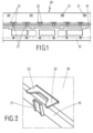
- ein Ausführungsbeispiel einer Anordnung einer Sensoreinrichtung mit einem Trägerkörper, an dem mehrere Sensoren anordbar sind,
- Figur 2
- ein erstes Ausführungsbeispiel von Befestigungsmitteln in Gestalt einer Befestigungslasche und eines Gegenhalters, die am Trägerkörper angeordnet sind und über die ein Sensor am Trägerkörper formschlüssig anordbar ist,
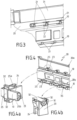
Figur 3- eine perspektivische Ansicht der Anordnung von zwei Sensoren an einem Trägerkörper,
- Figur 4
- eine weitere Ansicht der Anordnung eines Sensors an einem Trägerkörper mit einer weiteren Ausführungsform der Formschlusselemente,
- Figur 4a
- eine erste Ansicht eines Formschlusselementes, das als Befestigungsdom ausgeführt ist und in dem ein Clip verrastet ist,
- Figur 4b
- ein Befestigungsdom gemäß
Figur 4a für eine weitere Reihe von Formschlusselementen zur Anordnung eines weiteren Sensors, - Figur 5
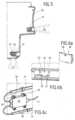
- eine Ansicht eines Querschnitts durch den Trägerkörper mit der Anordnung eines ersten Sensors für einen ersten Detektionsbereich und eines zweiten Sensors für einen zweiten Detektionsbereich,
- Figur 6a
- eine Ansicht einer Elektrikeinheit zur Anordnung an einem Trägerkörper,
- Figur 6b
- eine Ansicht einer Aufnahmeebene sowie zugeordnete Aufnahmemittel zur Anordnung einer Elektrikeinheit am Trägerkörper und
- Figur 6c
- eine Anordnung einer Elektrikeinheit an einem Trägerkörper, wobei zur Anordnung Befestigungsmittel in Gestalt von Schraubelementen vorgesehen sind.
- Figure 1
- an exemplary embodiment of an arrangement of a sensor device with a carrier body on which several sensors can be arranged,
- Figure 2
- a first exemplary embodiment of fastening means in the form of a fastening tab and a counter-holder, which are arranged on the carrier body and via which a sensor can be arranged in a form-fitting manner on the carrier body,
- Figure 3
- a perspective view of the arrangement of two sensors on a carrier body,
- Figure 4
- a further view of the arrangement of a sensor on a carrier body with a further embodiment of the positive locking elements,
- Figure 4a
- a first view of a positive locking element, which is designed as a fastening dome and in which a clip is locked,
- Figure 4b
- a fastening dome according to
Figure 4a for another series of positive locking elements for arranging another sensor, - Figure 5
- a view of a cross section through the carrier body with the arrangement of a first sensor for a first detection area and a second sensor for a second detection area,
- Figure 6a
- a view of an electrical unit for arrangement on a carrier body,
- Figure 6b
- a view of a recording plane and associated recording means for arranging an electrical unit on the carrier body and
- Figure 6c
- an arrangement of an electrical unit on a support body, fastening means in the form of screw elements being provided for the arrangement.
Zur formschlüssigen Aufnahme der Sensoren 10 am Trägerkörper 20 dienen Formschlusselemente, die gemäß des vorliegenden Ausführungsbeispiels in Gestalt von Befestigungslaschen 21 ausgeführt sind, wobei sowohl für den oberen Sensor 10 als auch für den unteren Sensor 10 jeweils sechs Befestigungslaschen 21 in einer jeweiligen Reihe angeordnet vorgesehen sind. Jeder Befestigungslasche 21 sind zwei Gegenhalter 22 zugeordnet, so dass der Sensor 10 durch die Befestigungslaschen 21 und die Gegenhalter 22 formschlüssig am Trägerkörper 20 aufgenommen werden kann. Die formschlüssige Aufnahme des Sensors 10 am Trägerkörper 20 durch die Befestigungslaschen 21 und die zugeordneten Gegenhalter 22 ist in
Zur Montage des Sensors 10 ist vorgesehen, dass der Sensor durch einen Monteur mit den Händen elastisch verformt wird, wobei das Material des Sensors vorzugsweise aus einem biegsamen, flexiblen Stoff hergestellt ist. Die Gegenhalter 22 sind benachbart neben der Befestigungslasche 21 angeordnet, so dass sich die Befestigungslasche 21 in einer L-förmigen Gestalt zwischen den beiden Gegenhaltern 22 befindet. Wird nun der Sensor 10 derart verbogen, dass sich der schlauchartige Körper des Sensors 10 zwischen den Gegenhaltern 22 und der Befestigungslasche 21 einfädeln lässt, so kann nach dem Einsetzen der Sensor 10 zwischen der Befestigungslasche 21 und den Gegenhaltern 22 wieder entspannt werden. Folglich nimmt der Sensor 10 durch elastische Rückverformung wieder seine alte Gestalt an und erstreckt sich im Wesentlichen in einer geraden Richtung. Im Ergebnis ist der Sensor 10 verliersicher und formschlüssig zwischen der Befestigungslasche 21 und den Gegenhaltern 22 am Trägerkörper 20 aufgenommen.To assemble the
Gemäß der Darstellung ist ein erster Sensor 10 in einer oberen Reihe von Formschlusselementen aufgenommen, wobei drei Befestigungslaschen 21 mit jeweils zugeordneten Gegenhaltern 22 gezeigt sind. Ebenso wie der erste Sensor 10 im oberen Bereich ist ein weiterer Sensor 10 im unteren Bereich angeordnet, der ebenfalls über eine Anzahl von Befestigungslaschen 21 mit zugeordneten Gegenhaltern 22 am Trägerkörper 20 angebracht ist.According to the illustration, a
In den
Die
Die Erfindung beschränkt sich in ihrer Ausführung nicht auf das vorstehend angegebene bevorzugte Ausführungsbeispiel. Vielmehr ist eine Anzahl von Varianten denkbar, welche von der dargestellten Lösung auch bei grundsätzlich anders gearteten Ausführungen Gebrauch macht. Sämtliche aus den Ansprüchen, der Beschreibung oder den Zeichnungen hervorgehenden Merkmale und/oder Vorteile einschließlich konstruktiven Einzelheiten, räumliche Anordnungen und Verfahrensschritte können sowohl für sich als auch in den verschiedensten Kombinationen erfindungswesentlich sein. Insbesondere sei angemerkt, dass die Formschlusselemente verschiedenartig ausgeführt sein können, wobei die verschiedenartige Ausführung jeweils miteinander kombiniert werden kann. Folglich kann an einem Trägerkörper 20 sowohl eine Kombination aus Befestigungslaschen 21 und Gegenhaltern 22 vorgesehen sein, die gleichermaßen auch mit Befestigungsdomen 23 zur Aufnahme von Sensoren 10 oder insbesondere zur Aufnahme nur eines Sensors 10 an einem Trägerkörper 20 kombiniert angeformt sein können. Ferner kann der Trägerkörper 20 als Stoßfänger am Kraftfahrzeug ausgeführt sein, so dass die jeweiligen Formschlusselemente zur Anordnung der Sensoren innenseitig am Stoßfänger vorhanden sein können und eine gleiche Ausgestaltung aufweisen können, wie vorliegend am separaten Trägerkörper 20 gezeigt.The implementation of the invention is not limited to the preferred exemplary embodiment given above. Rather, a number of variants are conceivable, which make use of the solution presented even in fundamentally different designs. All features and/or advantages arising from the claims, the description or the drawings, including constructive details, spatial arrangements and method steps, can be essential to the invention both individually and in a wide variety of combinations. In particular, it should be noted that the form-fitting elements can be designed in different ways, with the different designs being able to be combined with each other. Consequently, a combination of
- 1010
- Sensorsensor
- 2020
- Trägerkörper, TrägermodulCarrier body, carrier module
- 20a20a
- oberer Trägerbereichupper support area
- 20b20b
- unterer Trägerbereichlower support area
- 2121
- BefestigungslascheFastening tab
- 2222
- GegenhalterCounterholder
- 2323
- BefestigungsdomFortification dome
- 2424
- AufnahmetascheRecording bag
- 2525
- ClipClip
- 25a25a
- WiderhakenBarbs
- 25b25b
- WiderhakenBarbs
- 2626
- erster Detektionsbereichfirst detection area
- 2727
- zweiter Detektionsbereichsecond detection area
- 2828
- ElektrikeinheitElectrical unit
- 2929
- AufnahmemittelRecording means
- 3030
- Befestigungsmittel SchraubenelementFastener screw element
- 3131
- KraftfahrzeugelementMotor vehicle element
- 3232
- RastöffnungLatching opening
- 3333
- Aufnahmeebenerecording level
- 3434
- StufeLevel
- 3535
- StufeLevel
- 3636
- SensorelektrodeSensor electrode
- 3737
- Abschirmungshielding
- 3838
- Rastnasedetent nose
- 3939
- RastöffnungLatching opening
- 4040
- elektrische Verbindungelectrical connection
- 4141
- elektrische Verbindungelectrical connection
Claims (12)
- Arrangement of a sensor device with at least one sensor (10) for contactless activation of at least one moving part of a vehicle, especially a vehicle hatch, the sensor (10) being arranged on a bumper or a structural component on the vehicle, in order to permit a detection of an object in at least one detection range adjacent to the vehicle, so that an operation of the hatch can be activated via the detection,
characterized by the fact
that the sensor (10) is arranged in shape-mated and/or force-fit fashion on the bumper or structural component, wherein the bumper or the structural component has engagement elements, wherein the bumper or the structural component has, in its width direction, a first row of engagement elements and at least a second row of engagement elements running also in the width direction, in which the rows of engagement elements form an upper and lower row in the installed situation of the bumper or the structural component in the vehicle, in order to accommodate a first upper sensor (10) and a second lower sensor (10), and that the bumper or the structural element is also designed to accommodate an electrical unit (28), and especially a control unit, in which the electrical unit preferably can be arranged on the bumper or the structural element via mounting devices (29) that act in shape-mated fashion. - Arrangement according to Claim 1,
characterized by the fact
that a bumper or structural component is designed as an individually handled support module (20), so that the bumper or the structural component can be fastened as an essentially complete functional unit in and/or on the vehicle. - Arrangement according to one of the preceding claims,
characterized by the fact
that the at least one sensor (10) can be arranged via the engagement elements in shape-mated fashion on the bumper or the structural component, preferably at least one engagement element being designed in one part with the bumper or the structural component. - Arrangement according to Claim 3,
characterized by the fact
that at least a first engagement element is formed as a fastening tab (21) and protrudes, especially in L-shape, from an extension plane of the bumper or the structural component. - Arrangement according to Claim 3 or 4,
characterized by the fact
that at least a second engagement element is formed as a hold-down (22), which extends from the extension plane of the bumper or the structural component and has a position relative to the fastening tab (21), so that the sensor (10) is arranged secure from loss between the fastening tab (21) and the hold-down (22). - Arrangement according to claim 4 or 5,
characterized by the fact
that the sensor (10) has an elongated, preferably tube-like extent and preferably has a flexibility, so that the sensor (10) can be introduced by elastic deformation to be introduced by hand between the fastening tab (21) and preferably two hold-downs (22). - Arrangement according to one of the preceding claims,
characterized by the fact
that the bumper or the structural component has a stretched shape in a width direction and can be arranged in the vehicle, so that the width direction extends across the vehicle width, wherein in particular the sensor (10), with its elongated extent, is arranged in the width direction of the bumper or the structural element, so that the sensor (10) extends over the vehicle width, preferably in the rear area of the vehicle. - Arrangement according to one of the Claims 3 and 6 to 7,
characterized by the fact
that at least one engagement element is designed as a fastening dome (23), which has a receptacle (24) to accommodate the sensor (10). - Arrangement according to Claim 8,
characterized by the fact
that the fastening dome (23) is designed for shape-mated arrangement of a clip (25), which is designed as a mating element for the clamping arrangement of the sensor (10) between the receptacle (24) and clip (25). - Arrangement according to Claim 9,
characterized by the fact
that the clip (25) has a U-shaped configuration and has barbs (25a, 25b) on its free U-arms, which are designed for snapping into snap-in openings (32). - Arrangement according to Claim 1,
characterized by the fact
that the upper sensor (10) has a first detection range (26) that is designed for essentially horizontal recording in the range next to or behind the vehicle, and in which the lower sensor (10) has a second detection range (27), designed essentially for vertical recording in the region beneath the vehicle. - Arrangement according to Claim 1,
characterized by the fact
that the electrical unit (28) can be arranged with the bumper or the structural element via fastening devices (30), the fastening devices (30) preferably being designed as screw elements (30).
Applications Claiming Priority (2)
| Application Number | Priority Date | Filing Date | Title |
|---|---|---|---|
| DE102009033737A DE102009033737A1 (en) | 2009-07-17 | 2009-07-17 | Device for arranging sensors for an electronic actuation of a flap of a motor vehicle |
| EP10167850.6A EP2275296B1 (en) | 2009-07-17 | 2010-06-30 | Device for arranging sensors for electrical actuation of a motor vehicle hatch |
Related Parent Applications (3)
| Application Number | Title | Priority Date | Filing Date |
|---|---|---|---|
| EP10167850.6 Division | 2010-06-30 | ||
| EP10167850.6A Division-Into EP2275296B1 (en) | 2009-07-17 | 2010-06-30 | Device for arranging sensors for electrical actuation of a motor vehicle hatch |
| EP10167850.6A Division EP2275296B1 (en) | 2009-07-17 | 2010-06-30 | Device for arranging sensors for electrical actuation of a motor vehicle hatch |
Publications (4)
| Publication Number | Publication Date |
|---|---|
| EP2450207A2 EP2450207A2 (en) | 2012-05-09 |
| EP2450207A3 EP2450207A3 (en) | 2014-12-10 |
| EP2450207B1 EP2450207B1 (en) | 2018-11-28 |
| EP2450207B2 true EP2450207B2 (en) | 2023-09-20 |
Family
ID=42797140
Family Applications (5)
| Application Number | Title | Priority Date | Filing Date |
|---|---|---|---|
| EP13160021.5A Active EP2607123B1 (en) | 2009-07-17 | 2010-06-30 | Device for arranging sensors for electrical actuation of a motor vehicle hatch |
| EP10167850.6A Active EP2275296B1 (en) | 2009-07-17 | 2010-06-30 | Device for arranging sensors for electrical actuation of a motor vehicle hatch |
| EP12153333.5A Active EP2450207B2 (en) | 2009-07-17 | 2010-06-30 | Device for arranging sensors for electrical actuation of a motor vehicle hatch |
| EP20174129.5A Pending EP3730326A1 (en) | 2009-07-17 | 2010-06-30 | Device for arranging sensors for electrical actuation of a motor vehicle valve |
| EP23163088.0A Pending EP4234295A3 (en) | 2009-07-17 | 2010-06-30 | Device for arranging sensors for electrical actuation of a motor vehicle valve |
Family Applications Before (2)
| Application Number | Title | Priority Date | Filing Date |
|---|---|---|---|
| EP13160021.5A Active EP2607123B1 (en) | 2009-07-17 | 2010-06-30 | Device for arranging sensors for electrical actuation of a motor vehicle hatch |
| EP10167850.6A Active EP2275296B1 (en) | 2009-07-17 | 2010-06-30 | Device for arranging sensors for electrical actuation of a motor vehicle hatch |
Family Applications After (2)
| Application Number | Title | Priority Date | Filing Date |
|---|---|---|---|
| EP20174129.5A Pending EP3730326A1 (en) | 2009-07-17 | 2010-06-30 | Device for arranging sensors for electrical actuation of a motor vehicle valve |
| EP23163088.0A Pending EP4234295A3 (en) | 2009-07-17 | 2010-06-30 | Device for arranging sensors for electrical actuation of a motor vehicle valve |
Country Status (4)
| Country | Link |
|---|---|
| US (1) | US8441366B2 (en) |
| EP (5) | EP2607123B1 (en) |
| CN (3) | CN102602348B (en) |
| DE (1) | DE102009033737A1 (en) |
Families Citing this family (21)
| Publication number | Priority date | Publication date | Assignee | Title |
|---|---|---|---|---|
| DE102010037397A1 (en) * | 2010-09-08 | 2012-03-08 | Miele & Cie. Kg | Domestic appliance, in particular handle-less dishwasher |
| DE102012017843A1 (en) | 2012-02-25 | 2013-08-29 | Brose Fahrzeugteile Gmbh & Co. Kommanditgesellschaft, Hallstadt | Carrier for mounting electric or electronic component on motor vehicle, comprises a base structure which is flexibly adaptable to a space of motor vehicle, and one or more holding elements for mounting electric or electronic component |
| DE202012007455U1 (en) * | 2012-08-02 | 2013-11-05 | Brose Fahrzeugteile Gmbh & Co. Kommanditgesellschaft, Hallstadt | Actuating device for a movable vehicle part |
| WO2014199235A2 (en) | 2013-05-15 | 2014-12-18 | Magna Closures Inc. | Method and system for operating a closure panel of a vehicle |
| DE102013110866A1 (en) | 2013-10-01 | 2015-04-02 | Brose Fahrzeugteile Gmbh & Co. Kommanditgesellschaft, Hallstadt | Capacitive sensor arrangement of a motor vehicle |
| US9243441B2 (en) | 2014-02-28 | 2016-01-26 | Nissan North America, Inc. | System for remotely requesting activation of a vehicle function |
| US9243439B2 (en) | 2014-02-28 | 2016-01-26 | Nissan North America, Inc. | System for speech activated movement of a vehicle backdoor |
| DE102014107269A1 (en) * | 2014-05-22 | 2015-11-26 | Huf Hülsbeck & Fürst Gmbh & Co. Kg | Variable sensor unit |
| DE102014212780A1 (en) * | 2014-07-02 | 2016-01-07 | Robert Bosch Gmbh | Vehicle part with integrated sensor and method for its production |
| DE102014018924B4 (en) * | 2014-12-22 | 2017-03-16 | Brose Fahrzeugteile Gmbh & Co. Kommanditgesellschaft, Bamberg | Device for the contactless actuation of an adjustable vehicle part |
| DE102015000480B4 (en) | 2015-01-15 | 2018-03-08 | Audi Ag | Operating device for a motor vehicle with different operating areas and motor vehicle |
| EP3169958B1 (en) | 2015-04-27 | 2019-07-31 | LG Electronics Inc. | Refrigerator with door and refrigerator door manufacturing method |
| KR20230132597A (en) * | 2015-04-27 | 2023-09-15 | 엘지전자 주식회사 | Refrigerator |
| DE102015223573A1 (en) | 2015-11-27 | 2017-06-01 | Bayerische Motoren Werke Aktiengesellschaft | Collision detection device for a motor vehicle for detecting a collision with a pedestrian |
| DE102016213378A1 (en) * | 2016-07-21 | 2018-01-25 | Brose Fahrzeugteile Gmbh & Co. Kommanditgesellschaft, Bamberg | switching element |
| US10351086B2 (en) | 2016-09-30 | 2019-07-16 | Nissan North America, Inc. | Sensor mounting bracket |
| JP7067068B2 (en) * | 2018-01-11 | 2022-05-16 | 株式会社アイシン | Spacer for foreign matter detection sensor, terminal molding method of foreign matter detection sensor, and foreign matter detection sensor |
| JP6923460B2 (en) * | 2018-01-26 | 2021-08-18 | トヨタ自動車株式会社 | Vehicle undercarriage |
| DE102018115633A1 (en) | 2018-06-28 | 2020-01-02 | Huf Hülsbeck & Fürst Gmbh & Co. Kg | Sensor device for a vehicle |
| JP7267229B2 (en) * | 2020-04-08 | 2023-05-01 | ミネベアアクセスソリューションズ株式会社 | Motion detector |
| DE102022105948A1 (en) | 2022-03-15 | 2023-09-21 | Bayerische Motoren Werke Aktiengesellschaft | motor vehicle |
Citations (1)
| Publication number | Priority date | Publication date | Assignee | Title |
|---|---|---|---|---|
| JPH02144246A (en) † | 1988-11-25 | 1990-06-04 | Mazda Motor Corp | Capacitance type obstruction detecting device |
Family Cites Families (27)
| Publication number | Priority date | Publication date | Assignee | Title |
|---|---|---|---|---|
| DE29623461U1 (en) * | 1995-10-26 | 1998-07-23 | Valeo Securite Habitacle | System for hands-free unlocking and / or opening of opening devices of a motor vehicle |
| FR2740501B1 (en) * | 1995-10-26 | 1998-06-19 | Valeo Securite Habitacle | HANDS-FREE SYSTEM FOR UNLOCKING AND / OR OPENING THE VEHICLE OPENING ELEMENT |
| JPH11235961A (en) | 1998-02-20 | 1999-08-31 | Aisin Seiki Co Ltd | Object detecting device for vehicle |
| DE19961246A1 (en) * | 1999-05-18 | 2001-06-21 | Huf Huelsbeck & Fuerst Gmbh | Device for setting an opening and / or closing aid for lockable parts on vehicles, such as flaps, doors or the like. |
| EP1204542B1 (en) | 1999-07-29 | 2003-11-26 | AB Automotive Electronics Ltd. | Capacitive sensor |
| US6441623B1 (en) * | 1999-07-29 | 2002-08-27 | Ab Automotive Electronics Ltd. | Capacitive proximity sensor for automotive use |
| FR2823163B1 (en) * | 2001-04-04 | 2003-07-04 | Plastic Omnium Cie | AUTOMOTIVE VEHICLE EXTERIOR ELEMENT, INCLUDING A CAPACITIVE SENSOR AND BODY PIECE COMPRISING SUCH AN EXTERNAL ELEMENT |
| JP4251790B2 (en) * | 2001-06-19 | 2009-04-08 | 三菱電機株式会社 | Ultrasonic obstacle detection device and assembly method thereof |
| CN2491565Y (en) * | 2001-07-30 | 2002-05-15 | 上海现代凯麦拉机械有限公司 | Automatic unlocking device of sedan |
| CN101029883B (en) * | 2001-09-04 | 2010-06-16 | 株式会社阿尔宝 | Capacitive coupling type sensor device |
| CN2656223Y (en) * | 2003-04-05 | 2004-11-17 | 贵阳万江航空机电有限公司 | Vehicle rear baggage box cover opening device |
| DE10333735A1 (en) * | 2003-07-23 | 2005-03-03 | Peguform Gmbh & Co. Kg | Sensor device for a safety device in a vehicle |
| GB2386958A (en) | 2003-07-28 | 2003-10-01 | Ab Automotive Electronics Ltd | Integral capacitive sensor for proximity detection |
| DE10340263B4 (en) * | 2003-08-29 | 2014-12-18 | Magna Electronics Europe Gmbh & Co.Kg | Front structure for a motor vehicle |
| JP4222416B2 (en) * | 2004-04-26 | 2009-02-12 | 株式会社村田製作所 | Ultrasonic sensor |
| FR2870801B1 (en) * | 2004-05-28 | 2007-09-14 | Plastic Omnium Cie | BUMPER ABSORBER FOR MOTOR VEHICLE |
| GB2414881A (en) | 2004-06-01 | 2005-12-07 | Imp College Innovations Ltd | Imaging system capable of reproducing a wide range of intensities |
| DE102004037257A1 (en) * | 2004-07-31 | 2006-02-16 | Robert Bosch Gmbh | Mounting device for a sensor |
| DE102004041709C5 (en) * | 2004-08-28 | 2009-11-12 | Bayerische Motoren Werke Aktiengesellschaft | Vehicle with automatic opening flap |
| DE102004046860B4 (en) * | 2004-09-27 | 2009-01-02 | Continental Automotive Gmbh | Sensor arrangement and method for arranging a sensor in a vehicle |
| DE102004060618A1 (en) * | 2004-12-16 | 2006-07-06 | Siemens Restraint Systems Gmbh | Object e.g. pedestrian, collision detecting device for use on motor vehicle, has sensor device fastened to vehicle body shell by using clip connection for measuring force or deformation that is caused by collision of object on vehicle |
| DE102007009437A1 (en) | 2006-07-03 | 2008-01-17 | Plastal Gmbh | Bumper cover for motor vehicle bumper, has holding plate for holding mounted part, lumpy cable supports integrated in holding plate and formed with holding plate, and cable supports containing cable retainer for receiving cables |
| US8091280B2 (en) * | 2007-06-01 | 2012-01-10 | GM Global Technology Operations LLC | Arms full vehicle closure activation apparatus and method |
| US8098037B2 (en) * | 2007-11-08 | 2012-01-17 | Aisin Seiki Kabushiki Kaisha | Vehicle door opening-closing apparatus |
| DE202009018206U1 (en) | 2008-04-29 | 2011-05-05 | Volkswagen Ag | Device for actuating a door or flap of a vehicle |
| EP2159362B9 (en) * | 2008-09-02 | 2018-12-26 | Brose Fahrzeugteile GmbH & Co. KG, Bamberg | Vehicle with a device for automatic opening of at least a vehicle flap |
| DE102008063366B4 (en) * | 2008-12-30 | 2022-04-28 | Huf Hülsbeck & Fürst Gmbh & Co. Kg | Device for contactless actuation of a tailgate of a motor vehicle and method for actuating a tailgate of a motor vehicle and motor vehicle |
-
2009
- 2009-07-17 DE DE102009033737A patent/DE102009033737A1/en not_active Withdrawn
-
2010
- 2010-06-30 EP EP13160021.5A patent/EP2607123B1/en active Active
- 2010-06-30 EP EP10167850.6A patent/EP2275296B1/en active Active
- 2010-06-30 EP EP12153333.5A patent/EP2450207B2/en active Active
- 2010-06-30 EP EP20174129.5A patent/EP3730326A1/en active Pending
- 2010-06-30 EP EP23163088.0A patent/EP4234295A3/en active Pending
- 2010-07-15 CN CN201210074918.1A patent/CN102602348B/en active Active
- 2010-07-15 CN CN201010232288.7A patent/CN101954892B/en active Active
- 2010-07-15 CN CN201410610492.6A patent/CN104385886B/en active Active
- 2010-07-19 US US12/838,765 patent/US8441366B2/en active Active
Patent Citations (1)
| Publication number | Priority date | Publication date | Assignee | Title |
|---|---|---|---|---|
| JPH02144246A (en) † | 1988-11-25 | 1990-06-04 | Mazda Motor Corp | Capacitance type obstruction detecting device |
Also Published As
| Publication number | Publication date |
|---|---|
| CN104385886A (en) | 2015-03-04 |
| EP2275296B1 (en) | 2018-04-25 |
| CN101954892A (en) | 2011-01-26 |
| EP4234295A2 (en) | 2023-08-30 |
| CN102602348A (en) | 2012-07-25 |
| EP4234295A3 (en) | 2023-09-20 |
| EP2607123B1 (en) | 2020-05-13 |
| EP2607123A3 (en) | 2017-01-11 |
| EP2450207A3 (en) | 2014-12-10 |
| EP2275296A3 (en) | 2014-12-10 |
| CN102602348B (en) | 2015-11-04 |
| EP2275296A9 (en) | 2011-04-13 |
| EP2450207B1 (en) | 2018-11-28 |
| EP2450207A2 (en) | 2012-05-09 |
| EP2275296A2 (en) | 2011-01-19 |
| EP2607123A2 (en) | 2013-06-26 |
| EP3730326A1 (en) | 2020-10-28 |
| CN104385886B (en) | 2017-12-19 |
| US8441366B2 (en) | 2013-05-14 |
| CN101954892B (en) | 2015-05-13 |
| DE102009033737A1 (en) | 2011-01-27 |
| US20110012744A1 (en) | 2011-01-20 |
Similar Documents
| Publication | Publication Date | Title |
|---|---|---|
| EP2450207B2 (en) | Device for arranging sensors for electrical actuation of a motor vehicle hatch | |
| EP1810896B1 (en) | Assembly group with a rain sensor and a holding clip for the rain sensor. | |
| EP2753485B1 (en) | Control system | |
| DE102011121775B3 (en) | Control system for controlling e.g. motorized side door of motor car, has distance sensors with dummy portions such that sensors comprise no sensitivity or smaller sensitivity compared to region of each sensor adjacent to dummy portions | |
| EP3052348B1 (en) | Capacitive sensor arrangement of a motor vehicle | |
| DE202005003224U1 (en) | Profile rail insert for securing threaded nut for fixing bolt in profile rail slot, e.g. for mounting assembly securing solar module to building roof | |
| EP3169861B1 (en) | Inside door handle system for a door of a vehicle | |
| DE102012100428A1 (en) | Door handle for motor car, has printed circuit board, antenna, and sensor activated when motor car is locked, and another sensor activated when motor car is unlocked, fastened outside at shell, and electrically directly connected with board | |
| DE102015001851A1 (en) | Hooter system | |
| DE102005059413A1 (en) | Hinge for door of motor vehicle, has first fixing element and second fixing element, whereby hinge makes movement of door in arbitrary positions, comparable to robot arm | |
| EP1722454B1 (en) | Fastening device for cable | |
| WO2014079666A1 (en) | Capacitive sensor unit | |
| DE102017123065A1 (en) | Door handle with sensors | |
| DE102012020998A1 (en) | Locking device with multiple intervention | |
| DE202010003763U1 (en) | Capacitive sensor arrangement of a motor vehicle | |
| EP3576984B1 (en) | Horn actuation unit | |
| DE102021111989A1 (en) | Belt guide device for a passenger restraint belt of a motor vehicle | |
| DE19964507A1 (en) | U-shaped bracket for a with an outside door handle u. a door lock, provided vehicle door | |
| EP1383666B1 (en) | Interior fitting device for a vehicle, in particular a motor vehicle | |
| DE102015201967A1 (en) | Proximity sensor for a vehicle | |
| DE102014018923B4 (en) | Device for the contactless actuation of an adjustable vehicle part | |
| DE102013017221B4 (en) | Sensor module for contactless actuation of an adjustable vehicle part | |
| DE102020118080B4 (en) | holding device | |
| DE10037443B4 (en) | Device for connecting a door lock mounted on a holding element to a door module carrier of a motor vehicle door | |
| DE102014010368A1 (en) | Mounting device and method for mounting a first component to a second component of a motor vehicle, in particular a passenger car |
Legal Events
| Date | Code | Title | Description |
|---|---|---|---|
| PUAI | Public reference made under article 153(3) epc to a published international application that has entered the european phase |
Free format text: ORIGINAL CODE: 0009012 |
|
| AC | Divisional application: reference to earlier application |
Ref document number: 2275296 Country of ref document: EP Kind code of ref document: P |
|
| AK | Designated contracting states |
Kind code of ref document: A2 Designated state(s): AL AT BE BG CH CY CZ DE DK EE ES FI FR GB GR HR HU IE IS IT LI LT LU LV MC MK MT NL NO PL PT RO SE SI SK SM TR |
|
| AX | Request for extension of the european patent |
Extension state: BA ME RS |
|
| PUAL | Search report despatched |
Free format text: ORIGINAL CODE: 0009013 |
|
| AK | Designated contracting states |
Kind code of ref document: A3 Designated state(s): AL AT BE BG CH CY CZ DE DK EE ES FI FR GB GR HR HU IE IS IT LI LT LU LV MC MK MT NL NO PL PT RO SE SI SK SM TR |
|
| AX | Request for extension of the european patent |
Extension state: BA ME RS |
|
| RIC1 | Information provided on ipc code assigned before grant |
Ipc: B60J 5/10 20060101AFI20141104BHEP Ipc: E05F 15/20 20060101ALI20141104BHEP |
|
| 17P | Request for examination filed |
Effective date: 20150610 |
|
| RBV | Designated contracting states (corrected) |
Designated state(s): AL AT BE BG CH CY CZ DE DK EE ES FI FR GB GR HR HU IE IS IT LI LT LU LV MC MK MT NL NO PL PT RO SE SI SK SM TR |
|
| STAA | Information on the status of an ep patent application or granted ep patent |
Free format text: STATUS: EXAMINATION IS IN PROGRESS |
|
| 17Q | First examination report despatched |
Effective date: 20170310 |
|
| RIC1 | Information provided on ipc code assigned before grant |
Ipc: B60J 5/10 20060101AFI20180529BHEP |
|
| GRAP | Despatch of communication of intention to grant a patent |
Free format text: ORIGINAL CODE: EPIDOSNIGR1 |
|
| STAA | Information on the status of an ep patent application or granted ep patent |
Free format text: STATUS: GRANT OF PATENT IS INTENDED |
|
| INTG | Intention to grant announced |
Effective date: 20180717 |
|
| GRAS | Grant fee paid |
Free format text: ORIGINAL CODE: EPIDOSNIGR3 |
|
| GRAA | (expected) grant |
Free format text: ORIGINAL CODE: 0009210 |
|
| STAA | Information on the status of an ep patent application or granted ep patent |
Free format text: STATUS: THE PATENT HAS BEEN GRANTED |
|
| AC | Divisional application: reference to earlier application |
Ref document number: 2275296 Country of ref document: EP Kind code of ref document: P |
|
| AK | Designated contracting states |
Kind code of ref document: B1 Designated state(s): AL AT BE BG CH CY CZ DE DK EE ES FI FR GB GR HR HU IE IS IT LI LT LU LV MC MK MT NL NO PL PT RO SE SI SK SM TR |
|
| REG | Reference to a national code |
Ref country code: GB Ref legal event code: FG4D Free format text: NOT ENGLISH |
|
| REG | Reference to a national code |
Ref country code: CH Ref legal event code: EP |
|
| REG | Reference to a national code |
Ref country code: AT Ref legal event code: REF Ref document number: 1069796 Country of ref document: AT Kind code of ref document: T Effective date: 20181215 |
|
| REG | Reference to a national code |
Ref country code: DE Ref legal event code: R096 Ref document number: 502010015601 Country of ref document: DE |
|
| REG | Reference to a national code |
Ref country code: IE Ref legal event code: FG4D Free format text: LANGUAGE OF EP DOCUMENT: GERMAN |
|
| REG | Reference to a national code |
Ref country code: NL Ref legal event code: MP Effective date: 20181128 |
|
| REG | Reference to a national code |
Ref country code: LT Ref legal event code: MG4D |
|
| PG25 | Lapsed in a contracting state [announced via postgrant information from national office to epo] |
Ref country code: LV Free format text: LAPSE BECAUSE OF FAILURE TO SUBMIT A TRANSLATION OF THE DESCRIPTION OR TO PAY THE FEE WITHIN THE PRESCRIBED TIME-LIMIT Effective date: 20181128 Ref country code: FI Free format text: LAPSE BECAUSE OF FAILURE TO SUBMIT A TRANSLATION OF THE DESCRIPTION OR TO PAY THE FEE WITHIN THE PRESCRIBED TIME-LIMIT Effective date: 20181128 Ref country code: NO Free format text: LAPSE BECAUSE OF FAILURE TO SUBMIT A TRANSLATION OF THE DESCRIPTION OR TO PAY THE FEE WITHIN THE PRESCRIBED TIME-LIMIT Effective date: 20190228 Ref country code: HR Free format text: LAPSE BECAUSE OF FAILURE TO SUBMIT A TRANSLATION OF THE DESCRIPTION OR TO PAY THE FEE WITHIN THE PRESCRIBED TIME-LIMIT Effective date: 20181128 Ref country code: BG Free format text: LAPSE BECAUSE OF FAILURE TO SUBMIT A TRANSLATION OF THE DESCRIPTION OR TO PAY THE FEE WITHIN THE PRESCRIBED TIME-LIMIT Effective date: 20190228 Ref country code: IS Free format text: LAPSE BECAUSE OF FAILURE TO SUBMIT A TRANSLATION OF THE DESCRIPTION OR TO PAY THE FEE WITHIN THE PRESCRIBED TIME-LIMIT Effective date: 20190328 Ref country code: ES Free format text: LAPSE BECAUSE OF FAILURE TO SUBMIT A TRANSLATION OF THE DESCRIPTION OR TO PAY THE FEE WITHIN THE PRESCRIBED TIME-LIMIT Effective date: 20181128 Ref country code: LT Free format text: LAPSE BECAUSE OF FAILURE TO SUBMIT A TRANSLATION OF THE DESCRIPTION OR TO PAY THE FEE WITHIN THE PRESCRIBED TIME-LIMIT Effective date: 20181128 |
|
| PG25 | Lapsed in a contracting state [announced via postgrant information from national office to epo] |
Ref country code: SE Free format text: LAPSE BECAUSE OF FAILURE TO SUBMIT A TRANSLATION OF THE DESCRIPTION OR TO PAY THE FEE WITHIN THE PRESCRIBED TIME-LIMIT Effective date: 20181128 Ref country code: PT Free format text: LAPSE BECAUSE OF FAILURE TO SUBMIT A TRANSLATION OF THE DESCRIPTION OR TO PAY THE FEE WITHIN THE PRESCRIBED TIME-LIMIT Effective date: 20190328 Ref country code: GR Free format text: LAPSE BECAUSE OF FAILURE TO SUBMIT A TRANSLATION OF THE DESCRIPTION OR TO PAY THE FEE WITHIN THE PRESCRIBED TIME-LIMIT Effective date: 20190301 Ref country code: AL Free format text: LAPSE BECAUSE OF FAILURE TO SUBMIT A TRANSLATION OF THE DESCRIPTION OR TO PAY THE FEE WITHIN THE PRESCRIBED TIME-LIMIT Effective date: 20181128 |
|
| PG25 | Lapsed in a contracting state [announced via postgrant information from national office to epo] |
Ref country code: NL Free format text: LAPSE BECAUSE OF FAILURE TO SUBMIT A TRANSLATION OF THE DESCRIPTION OR TO PAY THE FEE WITHIN THE PRESCRIBED TIME-LIMIT Effective date: 20181128 |
|
| PG25 | Lapsed in a contracting state [announced via postgrant information from national office to epo] |
Ref country code: CZ Free format text: LAPSE BECAUSE OF FAILURE TO SUBMIT A TRANSLATION OF THE DESCRIPTION OR TO PAY THE FEE WITHIN THE PRESCRIBED TIME-LIMIT Effective date: 20181128 Ref country code: PL Free format text: LAPSE BECAUSE OF FAILURE TO SUBMIT A TRANSLATION OF THE DESCRIPTION OR TO PAY THE FEE WITHIN THE PRESCRIBED TIME-LIMIT Effective date: 20181128 Ref country code: IT Free format text: LAPSE BECAUSE OF FAILURE TO SUBMIT A TRANSLATION OF THE DESCRIPTION OR TO PAY THE FEE WITHIN THE PRESCRIBED TIME-LIMIT Effective date: 20181128 Ref country code: DK Free format text: LAPSE BECAUSE OF FAILURE TO SUBMIT A TRANSLATION OF THE DESCRIPTION OR TO PAY THE FEE WITHIN THE PRESCRIBED TIME-LIMIT Effective date: 20181128 |
|
| REG | Reference to a national code |
Ref country code: DE Ref legal event code: R026 Ref document number: 502010015601 Country of ref document: DE |
|
| PG25 | Lapsed in a contracting state [announced via postgrant information from national office to epo] |
Ref country code: SM Free format text: LAPSE BECAUSE OF FAILURE TO SUBMIT A TRANSLATION OF THE DESCRIPTION OR TO PAY THE FEE WITHIN THE PRESCRIBED TIME-LIMIT Effective date: 20181128 Ref country code: EE Free format text: LAPSE BECAUSE OF FAILURE TO SUBMIT A TRANSLATION OF THE DESCRIPTION OR TO PAY THE FEE WITHIN THE PRESCRIBED TIME-LIMIT Effective date: 20181128 Ref country code: SK Free format text: LAPSE BECAUSE OF FAILURE TO SUBMIT A TRANSLATION OF THE DESCRIPTION OR TO PAY THE FEE WITHIN THE PRESCRIBED TIME-LIMIT Effective date: 20181128 Ref country code: RO Free format text: LAPSE BECAUSE OF FAILURE TO SUBMIT A TRANSLATION OF THE DESCRIPTION OR TO PAY THE FEE WITHIN THE PRESCRIBED TIME-LIMIT Effective date: 20181128 |
|
| PLBI | Opposition filed |
Free format text: ORIGINAL CODE: 0009260 |
|
| PLAX | Notice of opposition and request to file observation + time limit sent |
Free format text: ORIGINAL CODE: EPIDOSNOBS2 |
|
| 26 | Opposition filed |
Opponent name: BROSE FAHRZEUGTEILE GMBH & CO. KOMMANDITGESELLSCHA Effective date: 20190828 Opponent name: IEE INTERNATIONAL ELECTRONICS & ENGINEERING S.A. Effective date: 20190825 |
|
| PG25 | Lapsed in a contracting state [announced via postgrant information from national office to epo] |
Ref country code: SI Free format text: LAPSE BECAUSE OF FAILURE TO SUBMIT A TRANSLATION OF THE DESCRIPTION OR TO PAY THE FEE WITHIN THE PRESCRIBED TIME-LIMIT Effective date: 20181128 |
|
| PLBB | Reply of patent proprietor to notice(s) of opposition received |
Free format text: ORIGINAL CODE: EPIDOSNOBS3 |
|
| PG25 | Lapsed in a contracting state [announced via postgrant information from national office to epo] |
Ref country code: MC Free format text: LAPSE BECAUSE OF FAILURE TO SUBMIT A TRANSLATION OF THE DESCRIPTION OR TO PAY THE FEE WITHIN THE PRESCRIBED TIME-LIMIT Effective date: 20181128 |
|
| REG | Reference to a national code |
Ref country code: CH Ref legal event code: PL |
|
| GBPC | Gb: european patent ceased through non-payment of renewal fee |
Effective date: 20190630 |
|
| REG | Reference to a national code |
Ref country code: BE Ref legal event code: MM Effective date: 20190630 |
|
| PG25 | Lapsed in a contracting state [announced via postgrant information from national office to epo] |
Ref country code: TR Free format text: LAPSE BECAUSE OF FAILURE TO SUBMIT A TRANSLATION OF THE DESCRIPTION OR TO PAY THE FEE WITHIN THE PRESCRIBED TIME-LIMIT Effective date: 20181128 |
|
| PG25 | Lapsed in a contracting state [announced via postgrant information from national office to epo] |
Ref country code: GB Free format text: LAPSE BECAUSE OF NON-PAYMENT OF DUE FEES Effective date: 20190630 Ref country code: IE Free format text: LAPSE BECAUSE OF NON-PAYMENT OF DUE FEES Effective date: 20190630 |
|
| PG25 | Lapsed in a contracting state [announced via postgrant information from national office to epo] |
Ref country code: CH Free format text: LAPSE BECAUSE OF NON-PAYMENT OF DUE FEES Effective date: 20190630 Ref country code: BE Free format text: LAPSE BECAUSE OF NON-PAYMENT OF DUE FEES Effective date: 20190630 Ref country code: LI Free format text: LAPSE BECAUSE OF NON-PAYMENT OF DUE FEES Effective date: 20190630 Ref country code: LU Free format text: LAPSE BECAUSE OF NON-PAYMENT OF DUE FEES Effective date: 20190630 |
|
| PG25 | Lapsed in a contracting state [announced via postgrant information from national office to epo] |
Ref country code: FR Free format text: LAPSE BECAUSE OF NON-PAYMENT OF DUE FEES Effective date: 20190630 |
|
| REG | Reference to a national code |
Ref country code: AT Ref legal event code: MM01 Ref document number: 1069796 Country of ref document: AT Kind code of ref document: T Effective date: 20190630 |
|
| PG25 | Lapsed in a contracting state [announced via postgrant information from national office to epo] |
Ref country code: AT Free format text: LAPSE BECAUSE OF NON-PAYMENT OF DUE FEES Effective date: 20190630 |
|
| PG25 | Lapsed in a contracting state [announced via postgrant information from national office to epo] |
Ref country code: CY Free format text: LAPSE BECAUSE OF FAILURE TO SUBMIT A TRANSLATION OF THE DESCRIPTION OR TO PAY THE FEE WITHIN THE PRESCRIBED TIME-LIMIT Effective date: 20181128 |
|
| PG25 | Lapsed in a contracting state [announced via postgrant information from national office to epo] |
Ref country code: HU Free format text: LAPSE BECAUSE OF FAILURE TO SUBMIT A TRANSLATION OF THE DESCRIPTION OR TO PAY THE FEE WITHIN THE PRESCRIBED TIME-LIMIT; INVALID AB INITIO Effective date: 20100630 Ref country code: MT Free format text: LAPSE BECAUSE OF FAILURE TO SUBMIT A TRANSLATION OF THE DESCRIPTION OR TO PAY THE FEE WITHIN THE PRESCRIBED TIME-LIMIT Effective date: 20181128 |
|
| APAH | Appeal reference modified |
Free format text: ORIGINAL CODE: EPIDOSCREFNO |
|
| APBM | Appeal reference recorded |
Free format text: ORIGINAL CODE: EPIDOSNREFNO |
|
| APBP | Date of receipt of notice of appeal recorded |
Free format text: ORIGINAL CODE: EPIDOSNNOA2O |
|
| APBM | Appeal reference recorded |
Free format text: ORIGINAL CODE: EPIDOSNREFNO |
|
| APBP | Date of receipt of notice of appeal recorded |
Free format text: ORIGINAL CODE: EPIDOSNNOA2O |
|
| APBM | Appeal reference recorded |
Free format text: ORIGINAL CODE: EPIDOSNREFNO |
|
| APBP | Date of receipt of notice of appeal recorded |
Free format text: ORIGINAL CODE: EPIDOSNNOA2O |
|
| APBQ | Date of receipt of statement of grounds of appeal recorded |
Free format text: ORIGINAL CODE: EPIDOSNNOA3O |
|
| PG25 | Lapsed in a contracting state [announced via postgrant information from national office to epo] |
Ref country code: MK Free format text: LAPSE BECAUSE OF FAILURE TO SUBMIT A TRANSLATION OF THE DESCRIPTION OR TO PAY THE FEE WITHIN THE PRESCRIBED TIME-LIMIT Effective date: 20181128 |
|
| APBU | Appeal procedure closed |
Free format text: ORIGINAL CODE: EPIDOSNNOA9O |
|
| P01 | Opt-out of the competence of the unified patent court (upc) registered |
Effective date: 20230425 |
|
| PGFP | Annual fee paid to national office [announced via postgrant information from national office to epo] |
Ref country code: DE Payment date: 20230630 Year of fee payment: 14 |
|
| PUAH | Patent maintained in amended form |
Free format text: ORIGINAL CODE: 0009272 |
|
| STAA | Information on the status of an ep patent application or granted ep patent |
Free format text: STATUS: PATENT MAINTAINED AS AMENDED |
|
| 27A | Patent maintained in amended form |
Effective date: 20230920 |
|
| AK | Designated contracting states |
Kind code of ref document: B2 Designated state(s): AL AT BE BG CH CY CZ DE DK EE ES FI FR GB GR HR HU IE IS IT LI LT LU LV MC MK MT NL NO PL PT RO SE SI SK SM TR |
|
| REG | Reference to a national code |
Ref country code: DE Ref legal event code: R102 Ref document number: 502010015601 Country of ref document: DE |