EP2449871B1 - Kartoffellegevorrichtung - Google Patents
Kartoffellegevorrichtung Download PDFInfo
- Publication number
- EP2449871B1 EP2449871B1 EP11008603.0A EP11008603A EP2449871B1 EP 2449871 B1 EP2449871 B1 EP 2449871B1 EP 11008603 A EP11008603 A EP 11008603A EP 2449871 B1 EP2449871 B1 EP 2449871B1
- Authority
- EP
- European Patent Office
- Prior art keywords
- supply container
- positioning
- potato
- tubers
- receiving space
- Prior art date
- Legal status (The legal status is an assumption and is not a legal conclusion. Google has not performed a legal analysis and makes no representation as to the accuracy of the status listed.)
- Active
Links
Images


Classifications
-
- A—HUMAN NECESSITIES
- A01—AGRICULTURE; FORESTRY; ANIMAL HUSBANDRY; HUNTING; TRAPPING; FISHING
- A01C—PLANTING; SOWING; FERTILISING
- A01C9/00—Potato planters
- A01C9/02—Potato planters with conveyor belts
Definitions
- the invention relates to a laying device for potatoes according to the preamble of claim 1.
- the reservoir is supported in the vicinity of the front tractor on the support frame having a support frame, and the laying unit also engages directly end in the reservoir.
- the isolated tubers are discharged during the laying phase in the seedbed in a far backward in the direction of travel position and adverse movement impulse.
- the positioning accuracy for the tuber layer is adversely affected.
- a length-increasing and stability-reducing juxtaposition of container and laying unit is provided, wherein the reservoir is provided with in the direction of travel of the tractor substantially in front of the laying units extending conveyors, so that here the tubers directly from the reservoir into the laying units be promoted.
- Potatoes are separated in a direction of travel of the laying machine behind a laying device arranged singler and stored by the laying device. Such a machine provides for manual monitoring of the laying operation.
- US 4,008,826 shows a potato planter with a arranged in the direction of travel in front of the laying unit reservoir.
- the potato is fed via a conveyor belt from the reservoir to the laying unit, which takes over the potatoes supplied and deposits against the direction of travel.
- the invention is concerned with the problem of creating a potato laying device in which previously provided laying units are largely without structural changes for machines with in the direction of travel in front of the laying unit reservoirs are used, while a weight-optimized design with improved control is also possible as excavation equipment and in the Close range of the support frame free spaces for additional aggregates are created.
- the device for laying potatoes is provided with a support frame, on which a storage container with in the direction of travel of the tractor in front of the laying units extending Gu Schl. is held so that it can be achieved optimal for different tractor conditions weight load of the system.
- the inventive improvement of a comparatively further forward displaceable center of gravity of the device enabling concept provides that starting from an upstream reservoir the respective cooperating with this and this downstream laying units continue to be supplied from its rear area with the tubers and at the same time advantageous close to the reservoir the tug is fixable.
- the potato-laying apparatus also provides that in the transverse direction thereof a storage container advantageously supported on the supporting frame is provided close to the towing vehicle and several of the laying units can be operated on the basis of this.
- each two laying units are fed with tubers.
- the tubers supplied continuously on the conveyor in the region of a divider can be introduced into the adjacent subregions of the respective takeover space. It is also conceivable to provide for each of the takeover rooms a separate conveyor and to provide this with appropriate controls and monitoring institutions.
- the inventive combination of the front - near the towing vehicle - positioned reservoir with the rearward conveyor to takeover room and the laying unit leads to an optimally cooperating unit and creates the possibility that at least partially below the front storage container additional processing equipment can be positioned.
- this space below the reservoir is also in known machines ( DE 20 2006 020 531 U1 ), but only with the inventive system of container-conveyor back-filling a compact design can be realized in which a plurality of cooperating as a processing set devices are arranged below a comparatively large reservoir.
- the storage location for the tubers, which can be achieved by the laying unit is optimally close to the center of gravity of the system, so that optimum setting conditions are achieved.
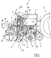
- a potato laying apparatus In Fig. 1 1, a potato laying apparatus, generally designated 1, is shown in a side view, with its supporting frame 2 being supported on a three-point support 3 of a tractor 4 shown schematically.
- the device 1 can be displaced in its entirety by means of a hydraulic power lift 5 - not shown in detail - for example in relation to a horizontal plane B (not shown).
- This construction is generically referred to as a lift-out unit carried on the stern ( DE 197 10 036 ) from which the drawn version ( EP 2 047 736 ) is different.
- Such devices for laying potatoes are provided with a total of 6 designated potato storage container. At least one laying unit 7 cooperates with this potato storage container 6, in its assembly designed as a circulating cup belt or the like, a separating element, the tubers K (FIG. Fig. 4 ) and laid out in a prepared seedbed 9. Also known are constructions in which the reservoir 6 has a in the direction of travel F of the tractor 4 substantially in front of the laying units 7 extending filling portion 10 ( Fig. 3 ) having.
- the inventive concept of the potato harvesting device 1 provides that in this the tubers K leaving the storage container 6 (FIG. Fig. 2 ) at least one the laying units 7 in each case - in relation to the direction of travel F - fed back area and only here by the separating members 8 are accepted.
- This supply can be carried out with largely variable executable guide and / or funding, and it is also conceivable that in the back in the open area also an immediate introduction into the separating organs of the laying unit 7 takes place (not shown).
- this is provided in the region of the laying units 7 in each case with at least one, the rear side at least partially surrounding takeover space A.
- the installation position of the laying unit 7 predetermining position is defined at the same time, so that the tubers K no longer taken directly at the output of the reservoir 6 of the separating organs 8, but on a "detour" -. B. on a corresponding guide or conveyor - are to move and can then be transported to the seedbed.
- the storage container 6 is provided with a supply assembly, generally designated 11. From the top view Fig. 3 It is clear that at least one conveyor 12 is provided for feeding the tubers K into the rear take-up room or spaces A. In the illustrated embodiment, the conveyor 12 engages in the filling region 10 of the reservoir 6 on the bottom side, so that from there the tubers K are displaced according to an arrow C to behind the "between parent" laying unit 7 and behind the vertical axis S. From the takeover room A out the tubers in the first conveying strand of the cup band 8 are isolated promoted (arrow H) and then moved down in the second winningtrum (arrow E). This makes it clear that the takeover space A can advantageously be designed in the manner of a temporary storage container 16. Therein, a partial volume of the tuber amount can be stored and accepted by the cup 17 of the belt 8.
- This filling system can also be controlled in the region of the respective drive members or motors M conveyor 12 so that either one of the laying units 7 is put out of service and thus bottom side at B creates a dam profile in the manner of an "empty track" in which no seed tubers K are contained.
- This floor area can later be called a rolling track for support wheels of Crop protection o.
- Exploiting devices are used. It is also conceivable, in the region of or the divider (s) 13 adjustable guide plates o. Like. Provide guide members, so that the deflection D, D 'causing divider 13 locked in one direction or the flow can be deflected (not shown) , so that, for example, one of the assigned two takeover spaces A is not filled.
- the additional longitudinal conveyor 12 to integrate a sensory monitoring of the optimal conveyor position in the system.
- tilting movements according to arrow N (FIG. Fig. 4 ) are detected and correcting displacements of the entire device and / or inclination adjustments of the conveyor 12 are activated in the region of corresponding actuators.
- further sensors into the system with which, in particular, also the conveying movement C and the filling state of the receiving space A are controlled.
- this is constructed so that the conveyor 12 forms the bottom outlet for the filling area 10 and thus a clearance is created below this connection area.
- the machine concept envisages that even a complex soil preparation - before the actual laying process at 7 - is to be integrated into the system.
- the area in front of the laying units 7 or the area below the front storage bin 6 can be used.
- the conveyor 12 respective tillage equipment 14, 15 - are arranged in different combinations.
- a horizontal cross member 20 of the support frame 2 is optimally arranged between laying unit 7 and reservoir 6, and the device combination 14, 15 is held in addition to the connection to the support frame 2 by means of respective support beams 21, 22.
- the construction according to the invention comprises a system in which tillage, laying and dam forms (at 23) can be carried out in an optimized sequence by means of a compact unit.
- a unit formed from storage container 6, conveyor 12 and laying unit 7 with takeover space A is shown, which engages with the support frame on the three-point support 3.
- the assembly also provided with a support frame may be, which is attachable by means of a support wheels train assembly to a tractor (not shown), so that a total of compact trailer variant (similar DE 10 2007 030 448 A1 ) is realized.
Landscapes
- Life Sciences & Earth Sciences (AREA)
- Soil Sciences (AREA)
- Environmental Sciences (AREA)
- Sowing (AREA)
- Pretreatment Of Seeds And Plants (AREA)
Priority Applications (1)
| Application Number | Priority Date | Filing Date | Title |
|---|---|---|---|
| PL11008603T PL2449871T3 (pl) | 2010-11-05 | 2011-10-27 | Sadzarka ziemniaków |
Applications Claiming Priority (1)
| Application Number | Priority Date | Filing Date | Title |
|---|---|---|---|
| DE102010050616A DE102010050616A1 (de) | 2010-11-05 | 2010-11-05 | Kartoffellegevorrichtung |
Publications (2)
| Publication Number | Publication Date |
|---|---|
| EP2449871A1 EP2449871A1 (de) | 2012-05-09 |
| EP2449871B1 true EP2449871B1 (de) | 2018-12-12 |
Family
ID=45540710
Family Applications (1)
| Application Number | Title | Priority Date | Filing Date |
|---|---|---|---|
| EP11008603.0A Active EP2449871B1 (de) | 2010-11-05 | 2011-10-27 | Kartoffellegevorrichtung |
Country Status (7)
| Country | Link |
|---|---|
| EP (1) | EP2449871B1 (pl) |
| DE (1) | DE102010050616A1 (pl) |
| DK (1) | DK2449871T3 (pl) |
| ES (1) | ES2708986T3 (pl) |
| HU (1) | HUE042845T2 (pl) |
| PL (1) | PL2449871T3 (pl) |
| TR (1) | TR201902922T4 (pl) |
Cited By (6)
| Publication number | Priority date | Publication date | Assignee | Title |
|---|---|---|---|---|
| US10729063B2 (en) | 2009-02-02 | 2020-08-04 | Deere & Company | Seeding machine with seed delivery system |
| USRE48572E1 (en) | 2009-02-02 | 2021-06-01 | Deere & Company | Planting unit for a seeding machine having blocking member to control hand-off of seed from a seed meter to a seed delivery system |
| US11051445B2 (en) | 2018-06-27 | 2021-07-06 | Deere & Company | Seeding system |
| US11058047B2 (en) | 2018-06-27 | 2021-07-13 | Deere & Company | Seeding system |
| US11064649B2 (en) | 2018-06-27 | 2021-07-20 | Deere & Company | Seeding system |
| US12514148B2 (en) | 2011-03-25 | 2026-01-06 | Deere & Company | Planting unit for a seeding machine having a seed meter and seed delivery system |
Families Citing this family (1)
| Publication number | Priority date | Publication date | Assignee | Title |
|---|---|---|---|---|
| DE202023103085U1 (de) * | 2023-06-05 | 2024-09-06 | Grimme Landmaschinenfabrik Gmbh & Co. Kg | Legevorrichtung für Hackfrüchte |
Family Cites Families (12)
| Publication number | Priority date | Publication date | Assignee | Title |
|---|---|---|---|---|
| DE331981C (de) * | 1918-08-25 | 1921-01-17 | Richard Held | Kartoffellegmaschine mit Becherwerk und angetriebenem Zellenrad zum Vereinzeln der Kartoffeln |
| US2053390A (en) * | 1933-12-21 | 1936-09-08 | Fred H Bateman | Assisted feed planter |
| DE2317036C3 (de) * | 1969-10-28 | 1979-03-29 | Paula 4509 Bad Essen Scheer Geb. Hupe | Selbsttätige Kartoffellegemaschine |
| US3690511A (en) * | 1970-08-17 | 1972-09-12 | Jack H Wigham | Conveyor belt spacer for potato planters |
| FR7407235A (pl) * | 1975-06-25 | 1900-01-01 | ||
| DE2900985C2 (de) | 1979-01-12 | 1980-12-11 | Maschinenfabrik Cramer, Inh. Cramer & Soehne, 2950 Leer | Störmeldeeinrichtung an Kartoffellegemaschinen |
| DE9401110U1 (de) | 1994-01-24 | 1994-05-11 | Maschinenfabrik August Gruse Gmbh, 31855 Aerzen | Maschine zum Legen von Kartoffeln in Beeten |
| DE19541553A1 (de) | 1995-11-08 | 1997-05-15 | Hassia Pflanztechnik Gmbh | Schöpfbecherband |
| DE19710036C2 (de) | 1997-03-12 | 2000-04-06 | Hassia Pflanztechnik Gmbh | Legemaschine für Kartoffeln |
| CN101119633B (zh) * | 2005-02-17 | 2013-04-03 | (小)安德烈埃斯·海斯 | 组合农业机器 |
| DE102007030448A1 (de) | 2007-06-29 | 2009-01-08 | Grimme Landmaschinenfabrik Gmbh & Co. Kg | Legemaschine für Kartoffeln |
| DE102007048637A1 (de) * | 2007-10-10 | 2009-04-16 | Grimme Landmaschinenfabrik Gmbh & Co. Kg | Legemaschine für Kartoffeln |
-
2010
- 2010-11-05 DE DE102010050616A patent/DE102010050616A1/de not_active Withdrawn
-
2011
- 2011-10-27 DK DK11008603.0T patent/DK2449871T3/en active
- 2011-10-27 ES ES11008603T patent/ES2708986T3/es active Active
- 2011-10-27 EP EP11008603.0A patent/EP2449871B1/de active Active
- 2011-10-27 PL PL11008603T patent/PL2449871T3/pl unknown
- 2011-10-27 HU HUE11008603A patent/HUE042845T2/hu unknown
- 2011-10-27 TR TR2019/02922T patent/TR201902922T4/tr unknown
Non-Patent Citations (1)
| Title |
|---|
| None * |
Cited By (11)
| Publication number | Priority date | Publication date | Assignee | Title |
|---|---|---|---|---|
| US10729063B2 (en) | 2009-02-02 | 2020-08-04 | Deere & Company | Seeding machine with seed delivery system |
| US10806070B2 (en) | 2009-02-02 | 2020-10-20 | Deere & Company | Seeding machine with seed delivery system |
| USRE48572E1 (en) | 2009-02-02 | 2021-06-01 | Deere & Company | Planting unit for a seeding machine having blocking member to control hand-off of seed from a seed meter to a seed delivery system |
| US11770994B2 (en) | 2009-02-02 | 2023-10-03 | Deere & Company | Seeding machine with seed delivery system |
| US11770995B2 (en) | 2009-02-02 | 2023-10-03 | Deere & Company | Seeding machine with seed delivery system |
| US11793104B2 (en) | 2009-02-02 | 2023-10-24 | Deere & Company | Seeding machine with seed delivery system |
| US11849665B2 (en) | 2009-02-02 | 2023-12-26 | Deere & Company | Seeding machine with seed delivery system |
| US12514148B2 (en) | 2011-03-25 | 2026-01-06 | Deere & Company | Planting unit for a seeding machine having a seed meter and seed delivery system |
| US11051445B2 (en) | 2018-06-27 | 2021-07-06 | Deere & Company | Seeding system |
| US11058047B2 (en) | 2018-06-27 | 2021-07-13 | Deere & Company | Seeding system |
| US11064649B2 (en) | 2018-06-27 | 2021-07-20 | Deere & Company | Seeding system |
Also Published As
| Publication number | Publication date |
|---|---|
| ES2708986T3 (es) | 2019-04-12 |
| DK2449871T3 (en) | 2019-04-01 |
| PL2449871T3 (pl) | 2019-05-31 |
| TR201902922T4 (tr) | 2019-03-21 |
| DE102010050616A1 (de) | 2012-05-10 |
| EP2449871A1 (de) | 2012-05-09 |
| HUE042845T2 (hu) | 2019-07-29 |
Similar Documents
| Publication | Publication Date | Title |
|---|---|---|
| EP2449871A1 (de) | Kartoffellegevorrichtung | |
| EP0323833B1 (de) | Sieb- und Fördereinrichtung | |
| DE3008380C2 (de) | Verfahren und Vorrichtung zum Fördern von Aushubmaterial aus einer Baugrube | |
| EP0216057B1 (de) | Pneumatische Einzelkornsämaschine | |
| DE3125659C2 (pl) | ||
| DE3247884A1 (de) | Verfahren zum aussaeen von saatgut und saemaschine zur durchfuehrung des verfahrens | |
| EP2792228B1 (de) | Streuvorrichtung | |
| DE4315343A1 (de) | Sämaschine | |
| DE4016878A1 (de) | Vorrichtung zur gleichmaessigen gutverteilung bei maehdreschern | |
| EP3367777B1 (de) | Landwirtschaftliche verteilmaschine mit dosiereinrichtung | |
| DE2037447A1 (de) | Vorrichtung zur schnellen Entleerung großer Kornbehälter in Mähdreschern Arim Clayson N V, Zeäelgem (Belgien) | |
| EP3610714B1 (de) | Einzelkornsäaggregat | |
| DE602005001032T2 (de) | Apparate für die Plazierung der Produkte in Blisters einer Blisterpackung | |
| DE1904273A1 (de) | Einzelkornsaemaschine | |
| EP0356606B1 (de) | Einzelkornsämaschine | |
| EP4566443B1 (de) | Vorrichtung und verfahren zum aufbereiten von liegeboxen für tiere | |
| EP3818804B1 (de) | Versorgungseinrichtung für eine kornvereinzelungsvorrichtung | |
| EP3701780B1 (de) | Sämaschinensystem | |
| DE817660C (de) | Kartoffelpflanzmaschine | |
| DE930832C (de) | Legemaschine | |
| DE102014006949B4 (de) | Trennvorrichtung für eine Kartoffelerntemaschine | |
| AT253286B (de) | Rübenhebemaschine | |
| EP0749678B2 (de) | Sämaschine | |
| DE473277C (de) | Kartoffellegmaschine mit einem oder mehreren um eine Vorratstrommel umlaufenden Kraenzen von Legschaufeln | |
| DE29511710U1 (de) | Sammel- und Mischvorrichtung für Silage |
Legal Events
| Date | Code | Title | Description |
|---|---|---|---|
| PUAI | Public reference made under article 153(3) epc to a published international application that has entered the european phase |
Free format text: ORIGINAL CODE: 0009012 |
|
| AK | Designated contracting states |
Kind code of ref document: A1 Designated state(s): AL AT BE BG CH CY CZ DE DK EE ES FI FR GB GR HR HU IE IS IT LI LT LU LV MC MK MT NL NO PL PT RO RS SE SI SK SM TR |
|
| AX | Request for extension of the european patent |
Extension state: BA ME |
|
| 17P | Request for examination filed |
Effective date: 20120613 |
|
| 17Q | First examination report despatched |
Effective date: 20160519 |
|
| STAA | Information on the status of an ep patent application or granted ep patent |
Free format text: STATUS: EXAMINATION IS IN PROGRESS |
|
| REG | Reference to a national code |
Ref country code: DE Ref legal event code: R079 Ref document number: 502011015137 Country of ref document: DE Free format text: PREVIOUS MAIN CLASS: A01C0009000000 Ipc: A01C0009020000 |
|
| RIC1 | Information provided on ipc code assigned before grant |
Ipc: A01C 9/02 20060101AFI20180430BHEP |
|
| GRAP | Despatch of communication of intention to grant a patent |
Free format text: ORIGINAL CODE: EPIDOSNIGR1 |
|
| STAA | Information on the status of an ep patent application or granted ep patent |
Free format text: STATUS: GRANT OF PATENT IS INTENDED |
|
| INTG | Intention to grant announced |
Effective date: 20180619 |
|
| GRAS | Grant fee paid |
Free format text: ORIGINAL CODE: EPIDOSNIGR3 |
|
| GRAA | (expected) grant |
Free format text: ORIGINAL CODE: 0009210 |
|
| STAA | Information on the status of an ep patent application or granted ep patent |
Free format text: STATUS: THE PATENT HAS BEEN GRANTED |
|
| AK | Designated contracting states |
Kind code of ref document: B1 Designated state(s): AL AT BE BG CH CY CZ DE DK EE ES FI FR GB GR HR HU IE IS IT LI LT LU LV MC MK MT NL NO PL PT RO RS SE SI SK SM TR |
|
| REG | Reference to a national code |
Ref country code: GB Ref legal event code: FG4D Free format text: NOT ENGLISH |
|
| REG | Reference to a national code |
Ref country code: CH Ref legal event code: EP |
|
| REG | Reference to a national code |
Ref country code: AT Ref legal event code: REF Ref document number: 1074764 Country of ref document: AT Kind code of ref document: T Effective date: 20181215 |
|
| REG | Reference to a national code |
Ref country code: DE Ref legal event code: R096 Ref document number: 502011015137 Country of ref document: DE |
|
| REG | Reference to a national code |
Ref country code: IE Ref legal event code: FG4D Free format text: LANGUAGE OF EP DOCUMENT: GERMAN |
|
| REG | Reference to a national code |
Ref country code: NL Ref legal event code: FP |
|
| REG | Reference to a national code |
Ref country code: DK Ref legal event code: T3 Effective date: 20190325 |
|
| REG | Reference to a national code |
Ref country code: ES Ref legal event code: FG2A Ref document number: 2708986 Country of ref document: ES Kind code of ref document: T3 Effective date: 20190412 |
|
| REG | Reference to a national code |
Ref country code: LT Ref legal event code: MG4D |
|
| PG25 | Lapsed in a contracting state [announced via postgrant information from national office to epo] |
Ref country code: LV Free format text: LAPSE BECAUSE OF FAILURE TO SUBMIT A TRANSLATION OF THE DESCRIPTION OR TO PAY THE FEE WITHIN THE PRESCRIBED TIME-LIMIT Effective date: 20181212 Ref country code: NO Free format text: LAPSE BECAUSE OF FAILURE TO SUBMIT A TRANSLATION OF THE DESCRIPTION OR TO PAY THE FEE WITHIN THE PRESCRIBED TIME-LIMIT Effective date: 20190312 Ref country code: FI Free format text: LAPSE BECAUSE OF FAILURE TO SUBMIT A TRANSLATION OF THE DESCRIPTION OR TO PAY THE FEE WITHIN THE PRESCRIBED TIME-LIMIT Effective date: 20181212 Ref country code: LT Free format text: LAPSE BECAUSE OF FAILURE TO SUBMIT A TRANSLATION OF THE DESCRIPTION OR TO PAY THE FEE WITHIN THE PRESCRIBED TIME-LIMIT Effective date: 20181212 Ref country code: HR Free format text: LAPSE BECAUSE OF FAILURE TO SUBMIT A TRANSLATION OF THE DESCRIPTION OR TO PAY THE FEE WITHIN THE PRESCRIBED TIME-LIMIT Effective date: 20181212 Ref country code: BG Free format text: LAPSE BECAUSE OF FAILURE TO SUBMIT A TRANSLATION OF THE DESCRIPTION OR TO PAY THE FEE WITHIN THE PRESCRIBED TIME-LIMIT Effective date: 20190312 |
|
| PG25 | Lapsed in a contracting state [announced via postgrant information from national office to epo] |
Ref country code: RS Free format text: LAPSE BECAUSE OF FAILURE TO SUBMIT A TRANSLATION OF THE DESCRIPTION OR TO PAY THE FEE WITHIN THE PRESCRIBED TIME-LIMIT Effective date: 20181212 Ref country code: GR Free format text: LAPSE BECAUSE OF FAILURE TO SUBMIT A TRANSLATION OF THE DESCRIPTION OR TO PAY THE FEE WITHIN THE PRESCRIBED TIME-LIMIT Effective date: 20190313 Ref country code: SE Free format text: LAPSE BECAUSE OF FAILURE TO SUBMIT A TRANSLATION OF THE DESCRIPTION OR TO PAY THE FEE WITHIN THE PRESCRIBED TIME-LIMIT Effective date: 20181212 Ref country code: AL Free format text: LAPSE BECAUSE OF FAILURE TO SUBMIT A TRANSLATION OF THE DESCRIPTION OR TO PAY THE FEE WITHIN THE PRESCRIBED TIME-LIMIT Effective date: 20181212 |
|
| REG | Reference to a national code |
Ref country code: HU Ref legal event code: AG4A Ref document number: E042845 Country of ref document: HU |
|
| PG25 | Lapsed in a contracting state [announced via postgrant information from national office to epo] |
Ref country code: PT Free format text: LAPSE BECAUSE OF FAILURE TO SUBMIT A TRANSLATION OF THE DESCRIPTION OR TO PAY THE FEE WITHIN THE PRESCRIBED TIME-LIMIT Effective date: 20190412 Ref country code: IT Free format text: LAPSE BECAUSE OF FAILURE TO SUBMIT A TRANSLATION OF THE DESCRIPTION OR TO PAY THE FEE WITHIN THE PRESCRIBED TIME-LIMIT Effective date: 20181212 |
|
| PG25 | Lapsed in a contracting state [announced via postgrant information from national office to epo] |
Ref country code: RO Free format text: LAPSE BECAUSE OF FAILURE TO SUBMIT A TRANSLATION OF THE DESCRIPTION OR TO PAY THE FEE WITHIN THE PRESCRIBED TIME-LIMIT Effective date: 20181212 Ref country code: SK Free format text: LAPSE BECAUSE OF FAILURE TO SUBMIT A TRANSLATION OF THE DESCRIPTION OR TO PAY THE FEE WITHIN THE PRESCRIBED TIME-LIMIT Effective date: 20181212 Ref country code: IS Free format text: LAPSE BECAUSE OF FAILURE TO SUBMIT A TRANSLATION OF THE DESCRIPTION OR TO PAY THE FEE WITHIN THE PRESCRIBED TIME-LIMIT Effective date: 20190412 Ref country code: EE Free format text: LAPSE BECAUSE OF FAILURE TO SUBMIT A TRANSLATION OF THE DESCRIPTION OR TO PAY THE FEE WITHIN THE PRESCRIBED TIME-LIMIT Effective date: 20181212 Ref country code: SM Free format text: LAPSE BECAUSE OF FAILURE TO SUBMIT A TRANSLATION OF THE DESCRIPTION OR TO PAY THE FEE WITHIN THE PRESCRIBED TIME-LIMIT Effective date: 20181212 |
|
| REG | Reference to a national code |
Ref country code: DE Ref legal event code: R097 Ref document number: 502011015137 Country of ref document: DE |
|
| PLBE | No opposition filed within time limit |
Free format text: ORIGINAL CODE: 0009261 |
|
| STAA | Information on the status of an ep patent application or granted ep patent |
Free format text: STATUS: NO OPPOSITION FILED WITHIN TIME LIMIT |
|
| PG25 | Lapsed in a contracting state [announced via postgrant information from national office to epo] |
Ref country code: SI Free format text: LAPSE BECAUSE OF FAILURE TO SUBMIT A TRANSLATION OF THE DESCRIPTION OR TO PAY THE FEE WITHIN THE PRESCRIBED TIME-LIMIT Effective date: 20181212 |
|
| 26N | No opposition filed |
Effective date: 20190913 |
|
| PG25 | Lapsed in a contracting state [announced via postgrant information from national office to epo] |
Ref country code: MC Free format text: LAPSE BECAUSE OF FAILURE TO SUBMIT A TRANSLATION OF THE DESCRIPTION OR TO PAY THE FEE WITHIN THE PRESCRIBED TIME-LIMIT Effective date: 20181212 |
|
| REG | Reference to a national code |
Ref country code: CH Ref legal event code: PL |
|
| PG25 | Lapsed in a contracting state [announced via postgrant information from national office to epo] |
Ref country code: CH Free format text: LAPSE BECAUSE OF NON-PAYMENT OF DUE FEES Effective date: 20191031 Ref country code: LU Free format text: LAPSE BECAUSE OF NON-PAYMENT OF DUE FEES Effective date: 20191027 Ref country code: LI Free format text: LAPSE BECAUSE OF NON-PAYMENT OF DUE FEES Effective date: 20191031 |
|
| PG25 | Lapsed in a contracting state [announced via postgrant information from national office to epo] |
Ref country code: CY Free format text: LAPSE BECAUSE OF FAILURE TO SUBMIT A TRANSLATION OF THE DESCRIPTION OR TO PAY THE FEE WITHIN THE PRESCRIBED TIME-LIMIT Effective date: 20181212 |
|
| PG25 | Lapsed in a contracting state [announced via postgrant information from national office to epo] |
Ref country code: MT Free format text: LAPSE BECAUSE OF FAILURE TO SUBMIT A TRANSLATION OF THE DESCRIPTION OR TO PAY THE FEE WITHIN THE PRESCRIBED TIME-LIMIT Effective date: 20181212 |
|
| PG25 | Lapsed in a contracting state [announced via postgrant information from national office to epo] |
Ref country code: MK Free format text: LAPSE BECAUSE OF FAILURE TO SUBMIT A TRANSLATION OF THE DESCRIPTION OR TO PAY THE FEE WITHIN THE PRESCRIBED TIME-LIMIT Effective date: 20181212 |
|
| PGFP | Annual fee paid to national office [announced via postgrant information from national office to epo] |
Ref country code: HU Payment date: 20251029 Year of fee payment: 15 |
|
| PGFP | Annual fee paid to national office [announced via postgrant information from national office to epo] |
Ref country code: NL Payment date: 20251023 Year of fee payment: 15 |
|
| REG | Reference to a national code |
Ref country code: DE Ref legal event code: R081 Ref document number: 502011015137 Country of ref document: DE Owner name: GRIMME LANDMASCHINENFABRIK SE & CO. KG, DE Free format text: FORMER OWNER: GRIMME LANDMASCHINENFABRIK GMBH & CO. KG, 49401 DAMME, DE |
|
| PGFP | Annual fee paid to national office [announced via postgrant information from national office to epo] |
Ref country code: DE Payment date: 20251020 Year of fee payment: 15 |
|
| PGFP | Annual fee paid to national office [announced via postgrant information from national office to epo] |
Ref country code: GB Payment date: 20251024 Year of fee payment: 15 |
|
| PGFP | Annual fee paid to national office [announced via postgrant information from national office to epo] |
Ref country code: AT Payment date: 20251021 Year of fee payment: 15 |
|
| PGFP | Annual fee paid to national office [announced via postgrant information from national office to epo] |
Ref country code: DK Payment date: 20251023 Year of fee payment: 15 |
|
| PGFP | Annual fee paid to national office [announced via postgrant information from national office to epo] |
Ref country code: FR Payment date: 20251029 Year of fee payment: 15 |
|
| PGFP | Annual fee paid to national office [announced via postgrant information from national office to epo] |
Ref country code: TR Payment date: 20251122 Year of fee payment: 15 Ref country code: BE Payment date: 20251022 Year of fee payment: 15 |
|
| PGFP | Annual fee paid to national office [announced via postgrant information from national office to epo] |
Ref country code: IE Payment date: 20251021 Year of fee payment: 15 Ref country code: CZ Payment date: 20251015 Year of fee payment: 15 |
|
| PGFP | Annual fee paid to national office [announced via postgrant information from national office to epo] |
Ref country code: PL Payment date: 20251014 Year of fee payment: 15 |
|
| PGFP | Annual fee paid to national office [announced via postgrant information from national office to epo] |
Ref country code: ES Payment date: 20251114 Year of fee payment: 15 |
|
| REG | Reference to a national code |
Ref country code: NL Ref legal event code: PD Owner name: GRIMME LANDMASCHINENFABRIK SE & CO. KG; DE Free format text: DETAILS ASSIGNMENT: CHANGE OF OWNER(S), CHANGE OF LEGAL ENTITY; FORMER OWNER NAME: GRIMME LANDMASCHINENFABRIK GMBH & CO. KG Effective date: 20260323 |