EP2448156B1 - Wireless base station device, mobile station device, and wireless communication method - Google Patents
Wireless base station device, mobile station device, and wireless communication method Download PDFInfo
- Publication number
- EP2448156B1 EP2448156B1 EP10792120.7A EP10792120A EP2448156B1 EP 2448156 B1 EP2448156 B1 EP 2448156B1 EP 10792120 A EP10792120 A EP 10792120A EP 2448156 B1 EP2448156 B1 EP 2448156B1
- Authority
- EP
- European Patent Office
- Prior art keywords
- orthogonal
- transmission
- code
- codes
- rss
- Prior art date
- Legal status (The legal status is an assumption and is not a legal conclusion. Google has not performed a legal analysis and makes no representation as to the accuracy of the status listed.)
- Active
Links
Images


Classifications
-
- H—ELECTRICITY
- H04—ELECTRIC COMMUNICATION TECHNIQUE
- H04B—TRANSMISSION
- H04B7/00—Radio transmission systems, i.e. using radiation field
- H04B7/02—Diversity systems; Multi-antenna system, i.e. transmission or reception using multiple antennas
- H04B7/04—Diversity systems; Multi-antenna system, i.e. transmission or reception using multiple antennas using two or more spaced independent antennas
- H04B7/06—Diversity systems; Multi-antenna system, i.e. transmission or reception using multiple antennas using two or more spaced independent antennas at the transmitting station
- H04B7/0613—Diversity systems; Multi-antenna system, i.e. transmission or reception using multiple antennas using two or more spaced independent antennas at the transmitting station using simultaneous transmission
- H04B7/0678—Diversity systems; Multi-antenna system, i.e. transmission or reception using multiple antennas using two or more spaced independent antennas at the transmitting station using simultaneous transmission using different spreading codes between antennas
-
- H—ELECTRICITY
- H04—ELECTRIC COMMUNICATION TECHNIQUE
- H04B—TRANSMISSION
- H04B7/00—Radio transmission systems, i.e. using radiation field
- H04B7/02—Diversity systems; Multi-antenna system, i.e. transmission or reception using multiple antennas
- H04B7/04—Diversity systems; Multi-antenna system, i.e. transmission or reception using multiple antennas using two or more spaced independent antennas
- H04B7/06—Diversity systems; Multi-antenna system, i.e. transmission or reception using multiple antennas using two or more spaced independent antennas at the transmitting station
- H04B7/0697—Diversity systems; Multi-antenna system, i.e. transmission or reception using multiple antennas using two or more spaced independent antennas at the transmitting station using spatial multiplexing
-
- H—ELECTRICITY
- H04—ELECTRIC COMMUNICATION TECHNIQUE
- H04J—MULTIPLEX COMMUNICATION
- H04J13/00—Code division multiplex systems
- H04J13/0003—Code application, i.e. aspects relating to how codes are applied to form multiplexed channels
-
- H—ELECTRICITY
- H04—ELECTRIC COMMUNICATION TECHNIQUE
- H04J—MULTIPLEX COMMUNICATION
- H04J13/00—Code division multiplex systems
- H04J13/0007—Code type
- H04J13/004—Orthogonal
-
- H—ELECTRICITY
- H04—ELECTRIC COMMUNICATION TECHNIQUE
- H04L—TRANSMISSION OF DIGITAL INFORMATION, e.g. TELEGRAPHIC COMMUNICATION
- H04L27/00—Modulated-carrier systems
- H04L27/26—Systems using multi-frequency codes
- H04L27/2601—Multicarrier modulation systems
- H04L27/2602—Signal structure
- H04L27/26035—Maintenance of orthogonality, e.g. for signals exchanged between cells or users, or by using covering codes or sequences
-
- H—ELECTRICITY
- H04—ELECTRIC COMMUNICATION TECHNIQUE
- H04L—TRANSMISSION OF DIGITAL INFORMATION, e.g. TELEGRAPHIC COMMUNICATION
- H04L27/00—Modulated-carrier systems
- H04L27/26—Systems using multi-frequency codes
- H04L27/2601—Multicarrier modulation systems
- H04L27/2602—Signal structure
- H04L27/261—Details of reference signals
- H04L27/2613—Structure of the reference signals
-
- H—ELECTRICITY
- H04—ELECTRIC COMMUNICATION TECHNIQUE
- H04L—TRANSMISSION OF DIGITAL INFORMATION, e.g. TELEGRAPHIC COMMUNICATION
- H04L5/00—Arrangements affording multiple use of the transmission path
- H04L5/0001—Arrangements for dividing the transmission path
- H04L5/0026—Division using four or more dimensions
-
- H—ELECTRICITY
- H04—ELECTRIC COMMUNICATION TECHNIQUE
- H04L—TRANSMISSION OF DIGITAL INFORMATION, e.g. TELEGRAPHIC COMMUNICATION
- H04L5/00—Arrangements affording multiple use of the transmission path
- H04L5/003—Arrangements for allocating sub-channels of the transmission path
- H04L5/0048—Allocation of pilot signals, i.e. of signals known to the receiver
-
- H—ELECTRICITY
- H04—ELECTRIC COMMUNICATION TECHNIQUE
- H04L—TRANSMISSION OF DIGITAL INFORMATION, e.g. TELEGRAPHIC COMMUNICATION
- H04L5/00—Arrangements affording multiple use of the transmission path
- H04L5/003—Arrangements for allocating sub-channels of the transmission path
- H04L5/0078—Timing of allocation
- H04L5/0082—Timing of allocation at predetermined intervals
-
- H—ELECTRICITY
- H04—ELECTRIC COMMUNICATION TECHNIQUE
- H04W—WIRELESS COMMUNICATION NETWORKS
- H04W88/00—Devices specially adapted for wireless communication networks, e.g. terminals, base stations or access point devices
- H04W88/02—Terminal devices
-
- H—ELECTRICITY
- H04—ELECTRIC COMMUNICATION TECHNIQUE
- H04W—WIRELESS COMMUNICATION NETWORKS
- H04W88/00—Devices specially adapted for wireless communication networks, e.g. terminals, base stations or access point devices
- H04W88/08—Access point devices
-
- H—ELECTRICITY
- H04—ELECTRIC COMMUNICATION TECHNIQUE
- H04L—TRANSMISSION OF DIGITAL INFORMATION, e.g. TELEGRAPHIC COMMUNICATION
- H04L25/00—Baseband systems
- H04L25/02—Details ; arrangements for supplying electrical power along data transmission lines
- H04L25/0202—Channel estimation
- H04L25/0204—Channel estimation of multiple channels
-
- H—ELECTRICITY
- H04—ELECTRIC COMMUNICATION TECHNIQUE
- H04L—TRANSMISSION OF DIGITAL INFORMATION, e.g. TELEGRAPHIC COMMUNICATION
- H04L5/00—Arrangements affording multiple use of the transmission path
- H04L5/003—Arrangements for allocating sub-channels of the transmission path
- H04L5/0058—Allocation criteria
- H04L5/006—Quality of the received signal, e.g. BER, SNR, water filling
-
- H—ELECTRICITY
- H04—ELECTRIC COMMUNICATION TECHNIQUE
- H04L—TRANSMISSION OF DIGITAL INFORMATION, e.g. TELEGRAPHIC COMMUNICATION
- H04L5/00—Arrangements affording multiple use of the transmission path
- H04L5/003—Arrangements for allocating sub-channels of the transmission path
- H04L5/0058—Allocation criteria
- H04L5/0073—Allocation arrangements that take into account other cell interferences
Definitions
- the present invention relates to a radio base station device, a mobile station device and a radio communication method for transmitting downlink reference signals.
- LTE Long Term Evolution
- WCDMA Wideband Code Division Multiple Access
- HSDPA High Speed Downlink Packet Access
- HSUPA High Speed Uplink Packet Access
- REL8-LTE radio access scheme in Release -8 LTE
- PFDMA Orthogonal Frequency Division Multiplexing Access
- the OFDM scheme is a multi-carrier transmission scheme in which a frequency band is divided into a plurality of narrow frequency bands (subcarriers) and data is transmitted in each of the subcarriers.
- subcarriers are arranged densely in the frequency axis while orthogonalized, it is possible to realize higher-speed transmission and increase the frequency use efficiency.
- the REL8-LTE defines a downlink reference signal structure.
- the downlink reference signal is used for the purpose of 1) measuring a downlink CQI (Channel Quality Indicator) for scheduling and adaptive control, 2) channel estimation for downlink synchronous detection in a user terminal (hereinafter referred to as LTE terminal) that supports the REL8-LTE and 3) estimating a state of downlink transmission channel for cell search and handover.
- CQI Channel Quality Indicator
- the REL8-LTE defines a radio transmission method, MIMO (Multiple-Input Multiple-Output), for improving the communication quality by providing a plurality of antennas in each of a transmitter and a receiver (see NPL1).
- MIMO Multiple-Input Multiple-Output
- This MIMO is classified into single MIMO in which the transmission layers (transmission information sequences) to be transmitted simultaneously are all of one user and multiuser MIMO in which they are of different users.
- each layer does not correspond one-to-one with a transmission antenna, but is transmission via all transmission antennas using different transmission phase/amplitude control (preceding).
- precoding layers ideally transmitted simultaneously are received as orthogonalized at the receiver (they do not interfere with each other).
- a precoding vector weighting of each transmission antenna
- the precoding enables such beam forming as realizes directional transmission while emphasizing desired wave for a specific user terminal.
- the multiuser MIMO is realized by allocating the same resource block of a certain subframe to layers of plural user terminals.
- the number of layers to allocate to each user is limited to one.
- Non-Patent Literature 1 3GPP TR 25.913[1]
- R1-091483 describes DL RS Design for LTE-Advanced. Antenna virtualization is applied to CRS in order to reduce its overhead. Cell- and antenna-specific CSI-RSs are defined. UE-specific DM-RS is defined for PDSCH demodulation.
- R1-092050 describes downlink RS structure in support of higher-order MIMO. Different patterns and multiplexing structures for multiple layer of transmission are considered.
- the DM-RS patterns are defined within a physical RB-pair. The patterns are chosen in a Release 8 compatible manner.
- R1-091517 describes UE-specific RS design for LTE-A. Overhead and multiplexing of UE-specific RS for smaller number of streams, considering power boost and scenario of high mobility are discussed.
- 3GPP contributions R1-094338 and R1-094234 relate to downlink DM-RS design for LTE-Advanced in order to support up to 8 layer transmission.
- OFCs orthogonal cover codes
- a mapping scheme for OCCs is proposed in which the mapping direction for the orthogonal cover codes in the frequency domain is alternatively reversed.
- the present invention was carried out in view of the foregoing and aims to provide a radio base station device and a radio communication method capable of performing wireless communications with use of a downlink reference signal structure suitable for increase in number of transmission layers.
- a first aspect of the present invention provides a radio base station device comprising: a plurality of transmission antennas; a reference signal generator for generating orthogonal reference signals based on a two-dimensional orthogonal code, the orthogonal reference signals being orthogonalized between downlink reference signals adjacent in two-dimensional directions of frequency direction and time direction to each other in one transmission layer and being orthogonalized in different transmission layers assigned to one radio resource; a multiplexer for multiplexing transmission data and the orthogonal reference signals in the one transmission layer; and a transmitter for transmitting a transmission signal obtained by multiplexing the transmission data and the orthogonal reference signals, via the transmission antenna in transmission layers simultaneously.
- the first aspect it is possible to orthogonalize the orthogonal downlink reference signals adj acent in the frequency direction in the one transmission layer, with use of the orthogonal code and also orthogonalize the orthogonal downlink reference signals adjacent in the time direction in the one transmission layer, with use of the orthogonal code.
- DM-RSs (Demodulation-Reference Signal) which are reference signals used in demodulation of shared data channel (PDSCH) in an LTE-A terminal are orthogonalized in different transmission layers.
- the DM-RSs multiplex in transmission data of respective transmission layers are orthogonalized in plural different transmission layers (four layers, eight layers, or more), for which a suitable downlink reference signal structure is described below.
- a downlink reference signal structure suitable for orthogonalizing DM-RSs which are to be orthogonalized in different transmission layers, in different users.
- a scheduler uses a reported value of CQI (channel quality indicator) of each frequency block given from each terminal (UE) as a basis to allocate radio resources of downlink shared channel (PDSCH) by unit of resource block (RB) at intervals of subframes.
- CQI channel quality indicator
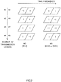
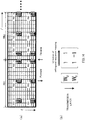
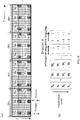
- Figs. 1(a) and 1(b) are conceptual diagrams of a downlink reference signal structure proposed by the inventors of the present invention.
- Fig. 1 (a) illustrates a DM-RS pattern per resource block.
- a frequency domain is composed of successive 12 subcarriers in accordance with the size of one resource block defined in LTE, and each subframe of the resource block is composed of 14 symbols.
- transmission data and a DM-RS are multiplexed in such a manner as to prevent overlapping in time and frequency domains.
- a DM-RS is prepared for each transmission layer. For example, where there are eight transmission layers, totally eight DM-RSs are generated corresponding to the eight transmission layers.
- a radio resource (time and frequency domains) (hereinafter referred to as "allocation resource") allocated to the DM-RS of one layer is expressed by "one subcarrier x successive two symbols".
- allocation resource is not limited and may be set to "two subcarriers x successive two symbols”.
- DM-RS of four transmission layers are multiplexed in one allocation resource.
- the multiplexing scheme of DM-RS adopted here is code division multiplexing (CDM) system.
- CDM code division multiplexing
- As DM-RSs of four transmission layers are multiplexed in one allocation resource if at least two allocation resources separated from each other in the frequency direction are secured in one resource block, DM-RSs of totally eight transmission layers can be multiplexed.
- three allocation resources are arranged as separated from each other in the frequency direction in one resource block.
- the DM-RSs of different transmission layers (four transmission layers) which are multiplexed to one allocation resource are orthogonal to each other.
- the DM-RSs multiplexed to one allocation resource are multiplied by four different orthogonal codes in accordance with the multiplex number so that the four DM-RSs of different transmission layers can be orthogonal to each other.
- Fig. 1(b) illustrates an, example of structure of two-dimensional orthogonal codes.
- the two-dimensional orthogonal codes W include a first orthogonal code W0 composed of 2 x 4 Walsh code and a second orthogonal code W1 composed of 2 x 4 Walsh code in which each line is orthogonal to a corresponding line of the first orthogonal code.
- the first and second orthogonal codes W0 and W1 are designed in size corresponding to the maximum multiplex number (four transmission layers) per allocation resource and an element size (1 x 2) of one allocation resource.
- three allocation resources R11, R12 and R13 are arranged as equally separated from each other in frequency direction and two allocation resources R21, R22 and R23 are arranged at the same subcarriers of the allocation resources R11, R12 and R13, respectively and separated by a predetermined number of symbols in time axis direction.
- DM-RSs corresponding to the first transmission layer #1 to the forth transmission layer #4 are code-division-multiplexed (CDM) to one allocation resource R11.
- Code division multiplexing of the four DM-RSs corresponding to the first transmission layer #1 to the forth transmission layer #4 multiplexed (CDM) to the allocation resource R11 is performed in such a manner that the DM-RSs are orthogonalized in the different transmission layers using the first orthogonal code W0.
- the DM-RSs corresponding to the first transmission layer #1 to the forth transmission layer #4 are multiplied by (-1, -1), (-1, 1), (1, 1), (1, -1) corresponding to the respective transmission layers and spread-multiplexed.
- FIG. 2 is a conceptual diagram of the four DM-RSs (first transmission layer #1 to fourth transmission layer #4) multiplexed to the allocation resource R11, which are code-division-multiplexed (orthogonalized) using the first orthogonal code W0.
- the DM-RSs (first transmission layer #1 to fourth transmission layer #4) are orthogonalized in the different transmission layers by the first orthogonal code W0.
- the allocation resource R12 is a radio resource adjacent in the frequency direction to the allocation resource R11.
- Four DM-RSs corresponding to the fifth transmission layer #5 to the eighth transmission layer #8 multiplexed to the allocation resource R12 are code-division-multiplexed in such a manner that the DM-RSs are orthogonalized in the different transmission layers using the second orthogonal code W1. This also means that the DM-RSs corresponding to the fifth transmission layer #5 to the eighth transmission layer #8 are multiplied by (1, 1), (1, -1), (-1, -1), (-1, 1) corresponding to the respective transmission layers and spread-multiplexed.
- FIG. 2 is a conceptual diagram of the four DM-RSs (fifth transmission layer #5 to eighth transmission layer #8) multiplexed to the allocation resource R12, which are code-division-multiplexed (orthogonalized) using the second orthogonal code W1 .
- the DM-RSs (fifth transmission layer #5 to eighth transmission layer #8) are orthogonalized in the different transmission layers by the second orthogonal code W1.
- the allocation resource R13 is a radio resource adjacent in the frequency direction to the allocation resource R12.
- FourDM-RSs (first transmission layer #1 to fourth transmission layer #4) multiplexed to the allocation resource R13 are code-division-multiplexed in such a manner that the DM-RSs are orthogonalized in the different transmission layers using the first orthogonal code W0.
- the DM-RSs of respective transmission layers (first transmission layer #1 to fourth transmission layer #4) and (fifth transmission layer #5 to eighth transmission layer #8) multiplexed to the allocation resources R11, R12 and R13 are orthogonal to each other in the different transmission layers in the respective allocation resources R11, R12 and R13.
- one DM-RSs (first transmission layer #1 to fourth transmission layer #4) multiplexed to the allocation resources (R11, R13) are orthogonal-multiplexed (spread-multiplexed) using the first orthogonal code W0 and the other DM-RSs (fifth transmission layer #5 to eighth transmission layer #8) multiplexed to the allocation resource (R12) are orthogonal-multiplexed (spread-multiplexed) using the second orthogonal code W1.
- orthogonalizing is performed between the allocation resources adjacent in the frequency direction (R11, R12) and between the allocation resources adjacent in the frequency direction (R12, R13).
- other three allocation resources R21, R22 and R23 are arranged at the same subcarriers of the above-mentioned three allocation resources R11, R12 and R13, respectively, and separated by a predetermined number of symbols in the time axis direction.
- the allocation resource R21 is adjacent to the above-mentioned allocation resource R11 in the time axis direction.
- Four DM-RSs corresponding to the fifth transmission layer #5 to the eighth transmission layer #8 are multiplexed to the allocation resource R21.
- the four DM-RSs (fifth transmission layer #5 to eighth transmission layer #8) multiplexed to the allocation resource R21 are code-division-multiplexed in such a manner that that the DM-RSs are orthogonalized in the different transmission layers using the second orthogonal code W1.
- FIG. 2 is a conceptual diagram of the four DM-RSs (fifth transmission layer #5 to eighth transmission layer #8) multiplexed to the allocation resource R21, which are code-division-multiplexed (orthogonalized) using the second orthogonal code W1.
- the DM-RSs (fifth transmission layer #5 to eighth transmission layer #8) are orthogonalized in the different transmission layers by the second orthogonal code W1.
- the allocation resource R22 is adjacent to the above-mentioned allocation resource R12 in the time axis direction.
- Four DM-RSs corresponding to the first transmission layer #1 to the fourth transmission layer #4 are multiplexed to the allocation resource R21.
- the four DM-RSs (first transmission layer #1 to fourth transmission layer #4) multiplexed to the allocation resource R22 are code-division-multiplexed in such a manner that that the DM-RSs are orthogonalized in the different transmission layers using the first orthogonal code W0.
- the allocation resource R23 is adjacent to the above-mentioned allocation resource R13 in the time axis direction.
- Four DM-RSs corresponding to the fifth transmission layer #5 to the eighth transmission layer #8 are multiplexed to the allocation resource R23.
- the four DM-RSs (fifth transmission layer #5 to eighth transmission layer #8) multiplexed to the allocation resource R23 are code-division-multiplexed in such a manner that that the DM-RSs are orthogonalized in the different transmission layers using the second orthogonal code W1.
- one DM-RSs (first transmission layer #1 to fourth transmission layer #4) multiplexed to the allocation resources (R11, R13, R22) are orthogonal-multiplexed (spread-multiplexed) using the first orthogonal code W0 and the other DM-RSs (fifth transmission layer #5 to eighth transmission layer #8) multiplexed to the allocation resource (R21, R12, R23) are orthogonal-multiplexed (spread-multiplexed) using the second orthogonal code W1.
- orthogonalizing is performed between the allocation resources adjacent in the time axis direction (R11, R21), between the allocation resources adjacent in the time axis direction (R12, R22) and between the allocation resources adjacent in the time axis direction (R13, R23).
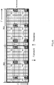
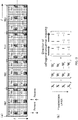
- Fig. 3 is a conceptual view of DM-RSs which are orthogonalized in two-dimensional directions composed of the frequency axis direction and time axis direction.
- Fig. 3 illustrates the orthogonal state in the transmission layer #2 of the four allocation resources R11, R12, R21 and R22 that are adjacent to each other in the two-dimensional directions (frequency axis direction and time axis direction). As illustrated in Fig.
- the DM-R,Ss in the allocation resources R11 and R12 adjacent to each other in the frequency axis direction enclosed in the dotted line L1 are orthogonal to each other and the DM-RSs in the allocation resources R12 and R22 adjacent to each other in the time axis direction enclosed in the dotted line L2 are orthogonal to each other. This orthogonalizing in the two-dimensional directions is assured in all of the transmission layers.
- the DM-RSs corresponding to the first transmission layer #1 to the fourth transmission layer #4 are code-division-multiplexed using the first orthogonal code W0 that is one two-dimensional orthogonal code W and the DM-RSs corresponding to the fifth transmission layer #5 to the eighth transmission layer #8 are code-division-multiplexed using the second orthogonal code W1 that is the other two-dimensional orthogonal code W.
- This is not intended for limiting the present invention.
- the DM-RSs are orthogonalized in different users using the first orthogonal code W0 and the second orthogonal code W1 of the two-ditnensional orthogonal codes W.
- first orthogonal code W0 illustrated in Fig. 1(b) first two codes (-1, -1) and (-1, 1) are allocated to the user UE1 (layers #1 to #2) and the following two codes (1, 1) and (1, -1) are allocated to the user UE2 (layers #1 to #2).
- the different users UE1 and UE2 are allocated to the allocation resources that are adjacent to each other in the frequency axis direction.
- the DM-RSs of plural layers (first transmission layer #1 and second transmission layer #2) for the user UE1 are code-division-multiplexed to the allocation resource R11 (R13) to which the users UE1 and UE2 are allocated, using the first two codes of the first orthogonal code W0 and the DM-RSs of plural layers (first transmission layer #1 and second transmission layer #2) for the user UE2 are also code -divis ion-mult iplexed to the allocation resource R11 (R13) using the following two codes of the first orthogonal code W0.
- the DM-RSs of the plural layers (third transmission layer #3 and fourth transmission layer #4) for the user UE1 are code-division-multiplexed to the allocation resource R12 using the first two codes of the second orthogonal code W1 and the DM-RSs of the plural layers (third transmission layer #3 and fourth transmission layer #4) for the user UE2 are code-division-multiplexed to the allocation resource R12 using the following two codes of the second orthogonal code W1.
- signals of plural users are orthogonally multiplexed in each allocation resource and orthogonalizing of the DM-RSs (first transmission layer #1 and second transmission layer #2) and (third transmission layer #3 and fourth transmission layer #4) of the plural users can be performed in the allocation resources R11 (R13) and R12 that are adjacent in the frequency axis direction to each other.
- the DM-RSs of plural layers (third transmission layer #3 and fourth transmission layer #4) for the user UE1 are code-division-multiplexed to the allocation resource R21 using the first two codes of the second orthogonal code W1 and the DM-RSs of plural layers (third transmission layer #3 and fourth transmission layer #4) for the user UE2 are code-division-multiplexed to the allocation resource R21 using the following two codes of the second orthogonal code W1.
- orthogonalizing of DM-RSs (first transmission layer #1 and second transmission layer #2) and DM-RSs (third transmission layer #3 and fourth transmission layer #4) for the plural users can be performed between the allocation resources R11 and R21 that are adjacent to each other in the time axis direction.
- orthogonalizing between users can be performed in the allocated allocation resources R12 and R22 and orthogonalizing can be performed between layers, and also, orthogonalizing between users can be performed in the allocated allocation resources R13 and R23 and orthogonalizing can be performed between layers.
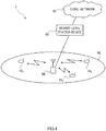
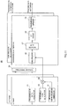
- a mobile communication system having user terminals (for example, mobile stations) and a radio base station device.
- the mobile communication system 1 is based on the LTE system, to which the radio communication method using CRS, CQI-RS, DM-RS as a downlink reference signal is applied.
- the mobile communication system 1 has a radio base station device 20, and a plurality of user terminals 10 (10 1 , 10 2 , 10 3 , ..., 10 n , n is a positive integer) that performs communications with the radio base station device 20.
- the radio base station device 20 is connected to a higher-level station, for example, an access gateway device 30, which is connected to a core network 40.
- Each user terminal 10 performs communications with the radio base station device 20 in a cell 50.
- the access gateway device 30 may be called MME/SGW (Mobility Management Entity/Serving Gateway).
- user terminals (10 1 , 10 2 , 10 3 , ..., 10 n ) have the same structures, functions and states, they are collectively explained as a user terminal 10 except where specifically noted.
- a user terminal 10 is a mobile station that performs radio communications with the radio base station device, but more typically, it is a user terminal (UE: User Equipment) including a mobile terminal and a fixed terminal.
- UE User Equipment
- OFDMA Orthogonal Frequency Division Multiple Access
- SC-FDMA Single Carrier- Frequency Division Multiple Access
- the OFDMA is a multi-carrier transmission scheme in which a frequency band is divided into a plurality of narrower frequency bands (subcarriers) and data is mapped to each subcarrier for communications.
- the SC-FDMA is a single carrier transmission scheme in which a system band is divided into bands composed of one or successive resource blocks per terminal and plural terminals use different bands thereby to reduce interference between the terminals.
- a reference signal for transmitting CRS, CQI-RS and DM-RS that are downlink reference signals, a physical downlink shared channel (PDSCH) shared by user terminals and a physical downlink control channel (downlink L1/L2 control channel).
- the reference signal is used to transmit a DM-RS with application of the above-mentioned multiplexing method.
- the physical downlink shared channel is used to transmit user data signals.
- the physical downlink control channel is used to notify DM-RS sequence information, scheduling information, user ID for performing communication with use of the physical downlink shared channel, transport format information of the user data, that is, downlink scheduling information, user ID for performing communications with use of the physical uplink shared channel and the transport format information of the user data, that is, Uplink Scheduling Grant.
- DM-RS sequence information is information for notifying user terminals of which index is used by PDCCH or higher layer signaling, when the DM-RSs define transmission layers #1 to #8 by indexes and single stream transmission is applied. When the multiplayer transmission is applied, a control signal is used to inform which index is used by other users multiplexed to the same resource blocks.
- broadcast channels such as Physical-Broadcast Channel (P-BCH) and Dynamic Broadcast Channel (D-BCH) are transmitted.
- Information to transmit in the P-BCH is Master Information Block (MIB) and information to transmit in the BCH is System Information Block (SIB).
- MIB Master Information Block
- SIB System Information Block
- the D-BCH is mapped to PDSCH and transmitted to the user terminal 10 by the radio base station device 20.
- the physical uplink shared channel (PUSCH) shared in user terminals 10 and the physical uplink control channel (PUCCH) which is uplink control channel are used.
- the physical uplink shared channel is used to transmit user data.
- the physical uplink control channel is used to transmit precoding information for downlink MIMO transmission, ACK/NACK for downlink shared channel, downlink radio quality information (CQI: Channel Quality Indicator) and the like.
- a physical random access channel (PRACH) is defined for initial connection or the like.
- PRACH physical random access channel
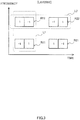
- the radio base station device 20 has a plurality of transmission antennas #1 to #N and transmission data and downlink reference signals (containing DM-RSs) of transmission layers are transmitted simultaneously from the plural transmission antennas.
- DM-RSs downlink reference signals
- the actual number of transmission antennas is eight for convenience for explanation. That is, the maximum number of transmission layers can be eight.
- the radio base station device 20 has a transmission data generator 21 for generating transmission data, an orthogonal RS sequence generator 22 for generating an orthogonal DM-RS, a multiplexer 23 for multiplexing transmission data and an orthogonal DM-RS, a scramble processor code generator 24 for generating a scramble code and a scramble processing section 25 for scrambling by multiplying the orthogonal DM-RS by the scramble code.
- generation of transmission data, generation of an orthogonal DM-RS, generation of a scramble code and multiplexing of transmission data and an orthogonal DM-RS are performed per transmission layer.
- the transmission data generator 21 performs error correction coding and interleaving on a symbol sequence of the transmission data.
- a turbo code is defined as a code having error correction ability for coding of the transmission data.
- the transmission data generator 21 After error correction coding and interleaving of the transmission data, the transmission data generator 21 performs serial-parallel conversion on the transmission data sequence (n bits that form one OFDM signal) to generate a data signal of plural sequences for subcarrier modulation. Interleaving may be performed after generation of the data signal of plural sequences.
- the transmission data generator 21 performs subcarrier modulation on the data signal of plural sequences in parallel. In the subcarrier modulation, modulation schemes such as BPSK, QPSK, 16QAM and the like may be adopted.
- Orthogonal DM-RSs corresponding to the transmission layers #1 to #4 are generated by the orthogonal RS sequence generators 22 (#1 to #4).
- the orthogonal RS sequence generator 22 (#1) generates an orthogonal DM-RS which is multiplexed to the transmission data of the transmission layer #1.
- the orthogonal RS sequence generator 22 (#1) generates the orthogonal DM-RS by multiplying the DM-RS of the transmission layer 1 by the first line (-1, -1) of the first orthogonal code W0.
- the orthogonal RS sequence generators 22 (#2 to #4) corresponding to the other transmission layers #2 to #4 multiply the DM-RS of the transmission layer #2 by the second line (-1, 1) of the first orthogonal code W0, the DM-RS of the transmission layer #3 by the third line (1, 1) of the first orthogonal code W0 and the DM-RS of the transmission layer #4 by the fourth line (1, -1) of the first orthogonal code W0.
- the orthogonal DM-RSs in the transmission layers #1 to #4 orthogonal to each other are generated.
- orthogonal DM-RSs corresponding to the transmission layers #5 to #8 are generated by the orthogonal RS sequence generators 22 (#5 to #8).
- the orthogonal RS sequence generator 22 (#5) generates an orthogonal DM-RS which is multiplexed to the transmission data of the transmission layer #5.
- the orthogonal RS sequence generator 22 (#5) generates the orthogonal DM-RS by multiplying the DM-RS of the transmission layer 5 by the first line (1, 1) of the second orthogonal code W1.
- the orthogonal RS sequence generators 22 (#6 to #7) corresponding to the other transmission layers #6 to #8 multiply the DM-RS of the transmission layer #6 by the second line (1, -1) of the second orthogonal code W1, the DM-RS of the transmission layer #7 by the third line (-1, -1) of the second orthogonal code W1 and the DM-RS of the transmission layer #8 by the fourth line (-1, 1) of the second orthogonal code W1.
- the orthogonal DM-RSs in the transmission layers #5 to #6 orthogonal to each other are generated.
- the orthogonal DM-RSs of the four transmission layers #1 to #4 generated by the orthogonal RS sequence generator 22 (#1 to #4) are multiplexed to the same allocation resources (R11, R13, R22). Accordingly, in each of the allocation resources (R11, R13, R22), the orthogonal DM-RSs of the four transmission layers #1 to #4 are orthogonally multiplexed.
- the orthogonal DM-RSs of the four transmission layers #5 to #8 generated by the orthogonal RS sequence generator 22 are multiplexed to the same allocation resources (R12, R21, R23). Accordingly, in each of the allocation resources (R12, R21, R23), the orthogonal DM-RSs of the four transmission layers #5 to #6 are orthogonally multiplexed.
- a group of the DM-RSs of the four transmission layers #1 to #4 and a group of the DM-RSs of the four transmission layers #5 to #8 are multiplexed separately.
- the reference signal structure of DM-RSs is based on the number of transmission layers "8".
- "Un#n" is added to follow the reference numeral "22" for convenience of explanation.
- the first two codes of the first and second orthogonal codes W0 and W1. are applied to the user UE1 and the following two codes are applied to the user UE2.
- the first two codes of the first and second orthogonal codes W0 and W1 are applied to the user UE1 and the following two codes are applied to the user UE2.
- the orthogonal DM-RSs corresponding to the transmission layers #1 and #2 of the user UE1 are generated by the orthogonal RS sequence generators 22 (U1#1, U1#2).
- the orthogonal RS sequence generator 22 (U1#1) multiplies the DM-RS sequence of the transmission layer #1 by the first line (-1, -1) of the first orthogonal code W0 to generate the orthogonal DM-RS.
- the orthogonal RS sequence generator 22 (U1#2) corresponding to the transmission layer #2 multiplies the DM-RS sequence of the transmission layer #2 by the second line (-1, 1) of the first orthogonal code W0.
- the orthogonal DM-RS corresponding to the transmission layer #1 of the user UE2 is generated by the orthogonal RS sequence generator 22 (U2#1) .
- the orthogonal RS sequence generator 22 (U2#1) multiplies the DM-RS sequence of the transmission layer #1 by the third line (1, 1) of the first orthogonal code W0 to generate the orthogonal DM-RS.
- the orthogonal RS sequence generator 22 (U2#2) corresponding to the transmission layer #2 multiplies the DM-R,S sequence of the transmission layer #2 by the fourth line (1, -1) of the first orthogonal code W0.
- the orthogonal DM-RSs corresponding to the transmission layers #3 and #4 of the user UE1 are generated by the orthogonal RS sequence generators 22 (U1#3, U1#4).
- the orthogonal RS sequence generator 22 (U1#3) multiplies the DM-RS sequence of the transmission layer #3 by the first line (1, 1) of the second orthogonal code W1 to generate the orthogonal DM-RS.
- the orthogonal RS sequence generator 22 (U1#4 corresponding to the transmission layer #4 multiplies the DM-RS sequence of the transmission layer #4 by the second line (1, -1) of the second orthogonal code W1.
- the orthogonal DM-RSs corresponding to the transmission layers #3 and #4 of the user UE2 are generated by the orthogonal RS sequence generators 22 (U2#3, U2#4).
- the orthogonal RS sequence generator 22 (U2#3) multiplies the DM-RS sequence of the transmission layer #3 by the third line (-1, -1) of the second orthogonal code W1 to generate the orthogonal DM-RS.
- the orthogonal RS sequence generator 22 (U2#4) corresponding to the transmission layer #4 multiplies the DM-RS sequence of the transmission layer #4 by the fourth line (-1, 1) of the second orthogonal code W1.
- the orthogonal DM-RSs of the transmission layers #1 and #2 generated by the orthogonal RS sequence generators 22 (U1#1, U1#2) for the user terminal UE1 and the orthogonal DM-RSs of the transmission layers #1 and #2 generated by the orthogonal RS sequence generators 22 (U2#1, U2#2) for the user terminal UE2 are multiplexed to the same allocation resources (R11, R13, R22).
- the orthogonal DM-RSs of the transmission layers #3 and #4 generated by the orthogonal RS sequence generators 22 (U1#3, U1#4) for the user terminal UE1 and the orthogonal DM-RSs of the transmission layers #3 and #4 generated by the orthogonal RS sequence generators 22 (U2#3, U2#4) for the user terminal UE2 are multiplexed to the same allocation resources (R12, R21, R23).
- the scramble code generator 24 generates a scramble code for making peripheral cell interference random.
- Two scramble methods including a user-specific scramble and a cell-specific scramble may be applied.
- scramble codes allocated to the users uniquely are used to scramble the orthogonal DM-RSs.
- the scramble sequence may be determined by the user ID given to each user or may be communicated to the user terminal by higher layer signaling.
- the scramble code may be determined by a cell ID of the connection cell (cell that receives the PDCCH9 or may be given from the connection cell by higher layer signaling (broadcast information or the like).
- Fig. 6 illustrates a scramble method when the user-specific scramble method is applied.
- the scramble processing section 25 has two multipliers 25a and 25b corresponding to orthogonal code sections.
- an orthogonal code section the same modulation symbol is multiplied to assure that the orthogonal code itself is not scrambled and only a part between the orthogonal codes is scrambled.
- one multiplier 25a multiplies (1, 1, 1, 1) as the same modulation symbol and the other multiplier 25b multiplies (-1, -1, -1, -1) as the same modulation symbol.
- scramble is performed between the orthogonal codes and is not performed within the orthogonal code section.
- RS i o i mod SF ⁇ s ⁇ i / SF ⁇
- a reference signal sequence (RS) of a sequence i is repeated at intervals of SF for the orthogonal sequence (o) and scrambled at intervals of SF.
- i/SF is a quotient obtained by dividing SF by i.
- the user-specific scramble method When the user-specific scramble method is applied, it is significant that scramble is not performed in the orthogonal code section.
- the orthogonal code As the orthogonal code is not scrambled, if scramble sequences are different, orthogonalization by the code is possible. That is, even between users of different connection cells (scramble sequences are differed), the DM-RSs can be orthogonalized and this is effective in application to multi-user MIMO over plural cells.
- Fig. 7 illustrates concept of the scramble method when the cell-specific scramble method is applied.
- the scramble processing section 25 multiplies the orthogonal codes by the cell-specific scramble codes.
- the scramble method of multiplying the orthogonal codes by the cell-specific scramble codes can be expressed in the equation (2).
- RS i o I • mod SF • s i
- the scramble method of the equation (1) for scrambling between orthogonal codes only may be applied to the cell-specific scramble method, or the scramble method of the equation (2) for scrambling the orthogonal codes may be applied to the user-specific scramble method.
- the reference signal sequence (RS) is expressed in two dimensions of time (t) and frequency (f).
- the orthogonal sequence (o) the time domain repeats at intervals of SF t and the frequency domain repeats at intervals of SF f
- scrambling the time domain is scrambled at intervals of SF t and the frequency domain is scrambled at intervals of SF f . That is, in this scramble method, scrambling is performed per resource block.
- the time domain is scrambled at intervals of SF t , however, the frequency domain is always scrambled. That is, the orthogonality of the orthogonal codes is maintained in the time domain but not in the frequency domain.
- This method is for improving the scramble effect in the frequency domain when scrambling per resource block as expressed in, the equation (3) has little effect.
- the frequency domain is scrambled at intervals of SF f , however, the time domain is always scrambled. That is, the orthogonality of the orthogonal codes is maintained in the frequency domain but not in the time domain.
- This method is for improving the scramble effect in the time domain when scrambling per resource block as expressed in the equation (3) has little effect.
- the multiplexer 23 multiplexes the transmission data and the orthogonal DM-RS on one resource block in such a manner that they do not overlap each other.
- the transmission data is mapped to white resource elements and the orthogonal DM-RS is mapped to the above-described allocation resources R11 to R13 and R21 to R23.
- the transmission data and the orthogonal DM-RS are multiplexed per transmission layer.
- the precoding section 26 determines a precoding vector in consideration of fading fluctuation in such a manner as to prevent interference in transmission layers to transmit simultaneously and to allow reception with high SINR at a user terminal.
- the user terminal chooses such a PMI (Precoding Matrix Indicator) that the reception SINR of each transmission layer is maximum and feeds it back.
- PMI Precoding Matrix Indicator
- the IFFT section 27 performs Inverse Fast Fourier Transform on a transmission signal (subcarrier signal) in the frequency domain to which the transmission data and the orthogonal DM-RS are subcarrier-mapped.
- a frequency-component signal allocated to a subcarrier is transformed to a time-component signal line.
- a CP adder 28 adds a cyclic prefix
- a transmission amplifier 29 amplifies power and then, the signal is transmitted via a transmission antenna.
- a reception processing system of the user terminal 10 receives a signal to which the orthogonal DM-RS and the transmission data are multiplexed per transmission layer as described above.
- a reception signal is input to a CP remover 31, in which the cyclic prefix is removed.
- a FFT section 32 performs Fast Fourier Transform on the CP-removed reception signal so that the time-sequence signal component is transformed into a frequency component line.
- a separator 33 performs subcarrier-demapping of the reception signal and separates a reference signal for transmitting the RS sequence signal, a control channel (for example, PHICH, PDCCH) for transmitting downlink control information and a shared channel (for example, PDSCH) for transmitting the transmission data.
- a control channel for example, PHICH, PDCCH
- a shared channel for example, PDSCH
- the orthogonal DM-RS is input to a multi-layer channel estimator 34.
- the PDSCH is input to a multi-layer demodulator 35 which is a demodulator of downlink transmission data.
- This multi-layer channel estimation is used as a basis to demodulate the transmission data.
- scramble information is communicated by higher layer signaling.
- the scramble information contains a repetition interval SF f of the frequency domain, a repetition interval SF t of the time domain and information for specifying a scramble code corresponding to each orthogonal code section.
- the multi-layer channel estimator 34 descrambles the DM-RS in accordance with the communicated scramble information.
- the DM-RS-s are orthogonalized by multiplying the DM-RS sequences by the first and second orthogonal codes (W0 , W1).
- the processing of multiplying the DM-RS sequences by the first and second orthogonal codes (W0, W1) can be deleted.
- the orthogonal codes W0 W1 are used to realize two-dimensional orthogonal codes.
- an orthogonal code is multiplied by a time domain and its multiplication direction (direction of the straight arrow in Fig.
- FIGs. 14 (a) and 14(b) are explanatory views of orthogonalizing when there are two transmission layers.
- orthogonalizing of DM-RSs of the transmission layer #1 in the time direction and frequency direction is realized by interchanging of the two-dimensional orthogonal codes shown in Fig. 9(b) in the multiplying direction. Accordingly, description is made about orthogonalization using two dimensional orthogonal codes of the transmission layer #2 on the basis of the two-dimensional orthogonal codes of the transmission layer #1.
- three allocation resources R51-R53 are arranged as equally separated from each other in the frequency direction in the resource block RB1.
- the allocation resources R61-R63 are arranged at the same subcarriers as the allocation resources R51-R53 and as separated by a predetermined number of symbols in the time direction from them.
- three allocation resources R54-R56 and three allocation resources R64-R66 are arranged in the same way in the resource block RB2 adjacent to the resource block RB1.
- the two-dimensional orthogonal code W 1 used in the transmission layer #2 is orthogonal to the two-dimensional orthogonal code W 0 used in the transmission layer #1.
- the two-dimensional orthogonal code W 0 of the transmission layer 1 as a basis is (1, 1), however, it is given for an illustrative purpose to specify the orthogonal relationship with the two-dimensional orthogonal code W 1 , for convenience of explanation.
- the DM-RSs are orthogonalized in the time and frequency directions like in the transmission layer #2.
- successive symbols of the allocation resource R51 illustrated in Fig. 14 (a) are multiplied by codes of the two-dimensional orthogonal code W1 sequentially in the forward direction with respect to the time indicated by the arrow.
- successive symbols of the allocation resource R61 are multiplied by codes of the two-dimensional orthogonal code W1 sequentially in the forward direction with respect to the time indicated by the arrow.
- the symbols at the allocation resources R52 and R62 adjacent in the frequency direction to the allocation resources R51 and R61, respectively are multiplied by codes of the two-dimensional orthogonal code W1 sequentially in the reverse direction to the time direction and multiplying direction is interchanged.
- the two-dimensional orthogonal code is mapped to a resource element group of the downlink reference signal of the same frequency domain, and the mapping directions of the codes are opposite in resource element groups adjacent in the frequency direction.
- the resource element groups are, allocation resources R51 and R61, the allocation resources R52 and R62, the allocation resources R53 and R63, the allocation resources R54 and R64, the allocation resources R55 and R65, and the allocation resources R56 and R66.
- the code (-1) is mapped to the first resource element in the forward direction, and the code (1) is mapped to the following resource element.
- the code (-1) is mapped to the first resource element in the forward direction, and the code (1) is mapped to the following resource element.
- two combinations of the codes (1, -1) are used in orthogonalizing of the DM-RSs.
- the code (1) is mapped to the first resource element in the reverse direction and the code (-1) is mapped to the following resource element.
- the code (1) is mapped to the first resource element in the reverse direction and the code (-1) is mapped to the following resource element. Accordingly, also between the allocation resources (R51, R52) and (R61, R62), the DM-RSs are orthogonalized by two combinations of codes (1, -1). Besides, also between other allocation resources, the same relation is shown.
- the two-dimensional orthogonal code W 1 is multiplied by the time domain and the multiplying direction is interchanged in the frequency domain so that the DM-RSs can be orthogonalized in the time direction, frequency direction and between the transmission layers #1, #2.
- orthogonalizing may be realized by reversing the multiplying direction of the two-dimensional orthogonal code in the frequency domain, as well as by reversing the multiplying direction of the two-dimensional orthogonal code in the time and frequency domains as illustrated in Fig. 15 .
- the two-dimensional orthogonal code is mapped to resource element groups of downlink reference signals of the same frequency domain and the code mapping directions are opposite in the resource element groups adjacent in the frequency and time directions.
- the resource element groups are allocation resources R51 to R56, R61 to R66.
- the code (1) is mapped to the first resource element in the time direction and the code (-1) is mapped to the following resource element.
- the code (-1) is mapped to the first resource element and the code (1) is mapped to the following resource element. Accordingly, between the allocation resources (R51, R61), the DM-RSs are orthogonalized by two combinations of code (1, -1).
- the code (-1) is mapped to the first resource element in the time direction and the code (1) is mapped to the following resource element. Accordingly, between, the allocation resources (R51, R52), the DM-RSs are orthogonalized by two combinations of code (1, -1). Also between other allocation resources, the same relation can be shown. With this structure, it is possible to realize orthogonalizing of DM-RSs in the time direction, frequency direction and between the transmission layers #1, #2.
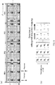
- FIGs. 16(a) and 16(b) are explanatory views of the first orthogonal pattern when there are four transmission layers.
- the DM-RSs in the transmission layer #1 are orthogonalized in the time direction and frequency direction and explanation is made about orthogonalizing of a higher-level transmission layer on the basis of two-dimensional orthogonal codes used in the transmission layer #1.
- allocation resource blocks R7a-R7c are arranged equally separated from each other in the frequency direction.
- allocation resources R8a-R8c are arranged at the same subcarriers as the allocation resources R7a-R7c, respectively, and separated from them by a predetermined number of symbols in the time direction.
- resource blocks RB2, RB3 and RB4 adjacent to the resource block RBl three allocation resources R7d-R7l and three allocation resources R8d-R8l are arranged as equally separated from each other in the same manner.
- two-dimensional orthogonal codes X 1 , X 2 and X 3 used in the transmission layers #2, #3 and #4 are orthogonal in layers to the two-dimensional orthogonal code X 0 used in the transmission layer #1.
- the two-dimensional orthogonal code X 0 of the transmission layer 1 as a basis is (1, 1, 1, 1), and this is given for an illustrative purpose to clarify the orthogonal relation with the two-dimensional orthogonal codes X 1 , X 2 , X 3 for convenience of explanation.
- the DM-RSs are orthogonal to each other in the time and frequency directions like in the transmission layer #2.
- each of the two-dimensional orthogonal codes X 1 , X 2 , X 3 is described as combination of first two codes (first code group) and latter two codes (second code group) .
- the first two codes correspond to the triangle arrow indicating the mapping direction (multiplying).
- the latter two codes correspond to the ⁇ -shaped arrow indicating the mapping direction (multiplying).
- the first two codes are (1, 1) and the latter two codes are (-1, -1).
- the first orthogonal pattern illustrated in Fig. 16 (a) is a pattern in which the first two codes and latter two codes are mapped to the resource element groups in this order.
- the resource element group is a pair of allocation resource R8n and R7n. That is, this orthogonal pattern is such that first two codes and latter two codes of the two-dimensional orthogonal code X 2 are allocated in the time direction and frequency direction alternately and as to the frequency direction, the mapping direction is reversed.
- the allocation resource R7a the latter two codes are mapped in the forward direction as indicated by the ⁇ -shaped arrow.
- the first two codes are mapped in the forward direction as indicated by the triangle arrow.
- first two codes are mapped in the reverse direction as indicated by the triangle arrow.
- the latter two codes are mapped in the reverse direction as indicated by the ⁇ -shaped arrow.
- the code (-1) is mapped to the first resource element in the time direction and the code (-1) is mapped to the following resource element.
- the code (1) is mapped to the first resource element in the time direction and the code (1) is mapped to the following resource element. Therefore, the DM-RSs are orthogonalized by two combinations of codes (1, 1) and (-1, -1) between the allocation resources (R7a, R8a).
- the code (1) is mapped to the first resource element in the time direction and the code (1) is mapped to the following resource element .
- the code (-1) is mapped to the first resource element in the time direction and the code (-1) is mapped to the following resource element.
- the DM-RSs are orthogonalized by two code combinations (1, 1) and (-1, -1) between allocation resources (R7a, R7b) and (R8a, R8b). Further, also between other allocation resources and other transmission layers, the DM-RSs are orthogonalized in the same manner.
- the DM-RSs are orthogonalized in the time direction, in the frequency direction and between transmission layers #1 to #4.
- the peak power of the first orthogonal pattern is discussed by the number of codes in which the mapping direction in the frequency direction is the same, it cannot be random in the first orthogonal pattern. For example, between the allocation resources R8a-R8l adjacent to each other in the frequency direction, (1, 1) is mapped to all of the allocation resources in the forward direction so that the peak power is increased.
- FIGs. 17 (a) and 17 (b) are explanatory views of the second orthogonal pattern when there are four transmission layers.
- the DM-RSs in the transmission layer #1 are orthogonalized in the time direction and in the frequency direction, and description is made about orthogonalizing in a higher-level transmission layer on the basis of the two-dimensional orthogonal codes used in the transmission layer #1.
- description is made about orthogonalizing in the second orthogonal pattern using the two-dimensional orthogonal code X 2 of the transmission layer #3.
- the second orthogonal pattern illustrated in Fig. 17(a) is an orthogonal pattern in which the order of the first two codes and latter two codes of the two-dimensional orthogonal code to be mapped to the above-mentioned resource element groups is reversed per plural resource blocks (here, two RBs).
- the second orthogonal pattern is realized by the same pattern structure as the first orthogonal pattern, of which the first two codes and the latter two codes of the two-dimensional orthogonal code X 2 are interchanged by unit of two resource block RBs.
- the number of RBs for interchanging the first and last two codes is not limited to two.
- the last two codes are mapped in the forward direction as indicated by the ⁇ -shaped arrow.
- the first two codes are mapped in the forward direction as indicated by the triangle arrow.
- the first two codes are mapped in the reverse direction as indicated by the triangle arrow.
- the last two codes are mapped in the reverse direction as indicated by the ⁇ -shaped arrow.
- the first two codes corresponding to the triangle arrow are interchanged with the last two codes corresponding to ⁇ -shaped arrow.
- the first two codes are mapped in the forward direction as indicated by the triangle arrow.
- the last two codes are mapped in the forward direction as indicated by the ⁇ -shaped arrow.
- the last two codes are mapped in the reverse direction as indicated by the ⁇ -shaped arrow.
- the first two codes are mapped in the reverse direction as indicated by the triangle arrow.
- the code (-1) is mapped to the first resource element in the time direction and the code (-1) is mapped to the following resource element.
- the code (1) is mapped to the first resource element in the time direction and the code (1) is mapped to the following resource element. Accordingly, between the allocation resources (R7a, R8a), the DM-RSs are orthogonalized by combination of codes (1, 1) and (-1, -1). In this way, as the first two codes and the last two codes are combined in the time direction, the DM-RSs can be maintained to be orthogonal to each other.
- the code (1) is mapped to the first resource element in the time direction and the code (1) is mapped to the last resource element.
- the code (-1) is mapped to the first resource element in the time direction and the code (-1) is mapped to the following resource element. Accordingly, the DM-RSs are orthogonalized also between the allocation resources (R7a, R7b) and (R8a, R8b) by combination of codes (1, 1) and (-1, -1).
- the code (1) is mapped to the first resource element in the time direction and the code (1) is mapped to the following resourceelement.
- the code (1) is mapped to the first resource element in the time direction and the code (1) is mapped to the following resource element. Accordingly, the DM-RSs are not orthogonalized by two combinations of code (1, 1) between the allocation resources (R7g, R7h).
- the code (-1) is mapped to the first resource element in the time direction and the code (-1) is mapped to the following resourceelement.
- the code (-1) is mapped to the first resource element in the time direction and the code (-1) is mapped to the following resource element. Accordingly, the DM-RSs are not orthogonalized by two combinations of code (-1, -1) between the allocation resources (R8g, R8h).
- the DM-RSs are orthogonalized in the resource blocks RB1 and RB2 (RB3 and RB4) but are not orthogonalized partially in the frequency direction.
- the DM-RSs are orthogonalized in the time direction and frequency direction, and its detail description is omitted here.
- the peak power of the second orthogonal pattern is made random as compared with that of the first orthogonal pattern. That is, the second orthogonal pattern is more random than the first orthogonal pattern as it has the same pattern structure as the first orthogonal pattern and the first two codes and last two codes of the two-dimensional orthogonal code are interchanged by unit of two resource blocks RBs.
- the second orthogonal pattern is more random than the first orthogonal pattern as it has the same pattern structure as the first orthogonal pattern and the first two codes and last two codes of the two-dimensional orthogonal code are interchanged by unit of two resource blocks RBs.
- (1, 1) is mapped to all the allocation resources in the forward direction
- R8g-R8l adjacent in the frequency direction of the resource blocks RB3 and RB4 (-1, -1) is mapped to all allocation resources in the forward direction. Accordingly, the peak power is prevented from increasing.
- Figs. 18(a) and 18(b) are explanatory views of the third orthogonal pattern when there are four transmission layers.
- the DM-RSs in the transmission layer #1 are orthogonalized in the time direction and frequency direction and description is made about orthogonalizing of a higher-level transmission layer on the basis of the two-dimensional orthogonal code used in the transmission layer #1.
- description is made about the orthogonalizing in the third orthogonal pattern using the two-dimensional orthogonal code X 2 of the transmission layer #3.
- the third orthogonal pattern illustrated in Fig. 18 (a) is an orthogonal pattern in which the order of the first two codes and the last two codes of the two-dimensional orthogonal code to be mapped to the above-mentioned resource element groups is reversed. That is, in the third orthogonal pattern, the first two codes and the last two codes of the two-dimensional orthogonal code X 2 are allocated in the time direction and in the frequency direction alternately by unit of two allocation resources adjacent in the frequency direction and the mapping direction is reversed in the frequency direction. For example, in the allocation resource R7a, the last two codes are mapped in the forward direction as indicated by the ⁇ -shaped arrow.
- the first two codes are mapped in the forward direction as indicated by the triangle arrow.
- the last two codes are mapped in the reverse direction as indicated by the ⁇ -shaped arrow.
- the first two codes are mapped as indicated by the triangle arrow.
- the first two codes are mapped in the forward direction as indicated by the triangle arrow.
- the last two codes are mapped in the forward direction as indicated by the ⁇ -shaped arrow.
- the first two codes are mapped in the reverse direction as indicated by the triangle arrow.
- the last two codes are mapped in the reverse direction as indicated by the ⁇ -shaped arrow.
- the code (-1) is mapped to the first resource element in the time direction and the code (-1) is mapped to the following resource element.
- the code (1) is mapped to the first resource element in the time direction and the code (1) is mapped to the following resource element. Accordingly, between the allocation resources (R7a, R8a), the DM-RSs are orthogonalized by combination of codes (1, 1) and (-1, -1). Thus, the orthogonality of the DM-RSs can be maintained as the first two codes and last two codes are combined in the time direction.
- the code (-1) is mapped to the first resource element in the time direction and the code (-1) is mapped to the following resource element.
- the code (1) is mapped to the first resource element in the time direction and the code (1) is mapped to the following resource element. Accordingly, the DM-RSs are not orthogonalized by two combinations of code (-1, -1) between the allocation resources (R7a, R7b). Besides, the DM-RSs are not orthogonalized by two combinations of code (1, 1) between the allocation resources (R8a, R8b).
- the code (1) is mapped to the first resource element in the time direction and the code (1) is mapped to the following resourceelement.
- the code (-1) is mapped to the first resource element in the time direction and the code (-1) is mapped to the following resource element.
- the DM-RSs are orthogonalized by combinations of codes (1, 1) and (-1, -1) between the allocation resources (R7b, R7c) and allocation resources (R8b, R8c).
- orthogonalizing of the DM-RSs is realized in the time direction, but not partially in the frequency direction.
- orthogonalizing of the DM-RSs in the time and frequency directions is realized in the transmission layers #2 and #4, detail description of which is omitted here.
- the peak power of the third orthogonal pattern is more random than that of the first orthogonal pattern. That is, the third orthogonal pattern is more random than the first pattern as the first two codes (last two codes) are interchanged by unit of two allocation resources adjacent in the frequency direction. For example, in the allocation resources R8a-R8f adjacent in the frequency direction, (1, 1) and (-1, -1) are mapped alternately to the allocation resources in the forward direction. Accordingly, increase in peak power can be further reduced.
- FIGs. 19 (a) and 19 (b) are explanatory views of the fourth orthogonal pattern when there are four transmission layers.
- the DM-RSs in the transmission layer #1 are orthogonalized in the time direction and frequency direction, and description is made about orthogonalizing of a higher-level transmission layer on the basis of the two-dimensional orthogonal code used in the transmission layer #1.
- the fourth orthogonal pattern illustrated in Fig. 19(a) is an orthogonal pattern in which in the same transmission layers, codes of the two-dimensional orthogonal code are mapped to a resource element group of downlink reference signals in the same frequency domains, the code mapping directions are opposite to each other by unit of plural resource element groups (here, two resource element groups) adjacent in the frequency direction, the two-dimensional orthogonal code is divided into first two codes and last two codes, the first two codes and the last two codes are mapped to a resource element group in this order and the order of the first two codes and the last two codes of the two-dimensional to be mapped to the resource element group is changed.
- resource element groups here, two resource element groups
- the fourth orthogonal pattern is realized by the first two codes and the last two codes of the two-dimensional orthogonal code X 2 alternately in the time direction and in the frequency direction and reversing the mapping direction in the frequency direction by unit of two allocation resources.
- the last two codes are mapped in the forward direction as indicated by the ⁇ -shaped arrow.
- the first two codes are mapped in the forward direction as indicated by the triangle arrow.
- the allocation resource R7b adjacent in the frequency direction to the allocation resource R7a the first two codes are mapped in the forward direction as indicated by the triangle arrow.
- the last two codes are mapped in the forward direction as indicated by the ⁇ -shaped arrow.
- the last two codes are mapped in the reverse direction as indicated by the ⁇ -shaped arrow.
- the first two codes are mapped in the reverse direction as indicated by the triangle arrow.
- the first two codes are mapped in the reverse direction as indicated by the triangle arrow.
- the last two codes are mapped in the reverse direction as indicated by the ⁇ -shaped arrow.
- the code (-1) is mapped to the first resource element in the time direction and the code (-1) is mapped to the following resourceelement.
- the code (1) is mapped to the first resource element in the time direction and the code (1) is mapped to the following resource element.
- the DM-RSs are orthogonalized by combination of codes (1, 1), (-1, -1). In this way, as the first two codes and the last two codes are combined in the time direction, the DM-RSs are maintained to be orthogonal to each other.
- the code (1) is mapped to the first resource element in the time direction and the code (1) is mapped to the following resource element.
- the code (-1) is mapped to the first resource element in the time direction and the code (-1) is mapped to the following resource element.
- the DM-RSs are orthogonalized by combination of codes (1, 1) and (-1, -1).
- the same results are obtained in other application resources and other transmission layers. In this way, orthogonalizing of the DM-RSs in the time direction, frequency direction and between the transmission layers #1 to #4 is realized also in the fourth orthogonal pattern.
- the peak power of the fourth orthogonal pattern is made more random than that of the first orthogonal pattern. That is, the fourth orthogonal pattern is more random than the first orthogonal pattern as the first and last codes of the same mapping directions are adjacent to each other. For example, in the allocation resources R8a-R8f adjacent in the frequency direction, (1, 1) and (-1, -1) are mapped alternately to the allocation resources adjacent in the forward direction. Accordingly, increase in peak power can be further reduced.
- orthogonalizing in the time and frequency directions and between the transmission layers #1 to #4 is realized in the first orthogonal pattern, however, the peak power is not random.
- orthogonalizing of the DM-RSs is not realized partially in the frequency direction, but the peak power becomes random as compared with the case of the first orthogonal pattern.
- orthogonalizing in the time and frequency directions and between the transmission layers #1 to #4 is realized and the peak power is made random as compared with the case of the first orthogonal pattern.
- orthogonalizing of the DM-RSs between the transmission layers #1 to #4, particularly, orthogonalizing in the transmission layer #1 can be achieved in the two dimensions composed of the time and frequency directions.
- the two-dimensional orthogonal code may be generated by cyclic-shifting the orthogonal code in the frequency domain.
- this method it is also possible to generate the orthogonal codes, no matter which of time and frequency is selected for inverse spread processing.
- description is made, with reference to Fig.20 ,aboutorthogonalizingrealized bycyclic-shifting of the two-dimensional orthogonal codes.
- allocation resources R91-R93 are arranged as equally separated from each other in the frequency direction in the resource block RB1.
- allocation resources R101-R103 are arranged at the same subcarriers of the allocation resources R91-R93, respectively and as separated from them by a predetermined number of symbols in the time direction.
- the two-dimensional orthogonal codes W 1 , W 2 , W 3 used in the transmission layers #2, #3, #4 are orthogonal in layers to the two-dimensional orthogonal code W 0 used in the transmission layer #1.
- Each code of the two-dimensional orthogonal codes W 1 , W 2 , W 3 is mapped while being shifted in the cyclic direction indicated by the arrow between plural resource element groups arranged in the frequency direction.
- the cyclic shifting is repeated in the order of (1, 1, -1, -1), (-1, 1, 1, -1), (-1, -1, 1, 1) and (1, -1, -1, 1).
- a resource element group is made of a pair of allocation resources 9n and 10n.
- each code of the two-dimensional orthogonal code W 2 is allocated per group.
- Each code of the two-dimensional orthogonal code W2 allocated to each group is cyclic-shifted by one code in the frequency direction. That is, this orthogonal pattern is realized by in plural resource element groups arranged in the frequency direction, shifting each code of the two-dimensional orthogonal code W 2 by one code per resource element group toward the high frequency side and mapping the code. For example, (1, 1, -1, -1) is mapped in the resource element groups R91, R101 and (-1, 1, 1, -1) is mapped to the resource element groups R92, R102 adjacent in the frequency direction to the resource element groups R91, R101.
- the code (-1) is mapped to the first resource element in the time direction and the code (-1) is mapped to the following resource element.
- the code (1) is mapped to the first resource element in the time direction and the code (1) is mapped to the following resource element.
- each code of the two-dimensional orthogonal code W 2 is mapped.
- each code of the two-dimensional orthogonal codes W 0 , W 1 and W 3 is also mapped. Accordingly, in the resource element groups R91 and R101, orthogonalizing can be realized with other transmission layers #1, #2 and #4 between transmission layers.
- each code of the two-dimensional orthogonal code W 2 cyclic-shifted by one code is mapped.
- respective codes of the two-dimensional orthogonal codes W 0 , W 1 , W 5 cyclic-shifted by one code are mapped. Accordingly, in the resource elements R92, R102, orthogonalizing between transmission layers with the other transmission layers #1, #2, #4 is also realized in the frequency direction.
- the code (-1) is mapped to the first resource element in the time direction and the code (1) is mapped to the following resource element.
- the code (-1) is mapped to the first resource element in the time direction and the code (-1) is mapped to the following resource element.
- the code (1) is mapped to the first resource element in the time direction and the code (-1) is mapped to the following resource element.
- (1, -1, -1, 1) is mapped to a group composed of first resource elements in the transmission direction of the allocation resources R101 to R104, and (1, 1, -1, -1) is mapped to a group of following resource elements. That is, in the resource elements at the same subframe of the allocation resources R101 to R104, each code of the two-dimensional orthogonal code W 2 is mapped as shifted by one code to the first elements in the time direction. In this way, when each code of the two-dimensional orthogonal code W 2 is cyclic-shifted by one code in the frequency direction, each code of the two-dimensional orthogonal code W 2 is also cyclic-shifted by one code in the time direction.
- the peak power of the orthogonal pattern is more random as compared with the structure where orthogonalizing between transmission layers is realized by interchanging two-dimensional orthogonal codes in the mapping direction. Accordingly, the peak power is prevented from increasing.
- orthogonalizing between the transmission layers #1 to #4 can be realized in two dimensions of time direction and frequency direction, and the peak power can be made random.
- a set composed of two codes (1) and two codes (-1) is mapped to the resource elements arranged in the time and frequency directions.
- orthogonalizing of the DM-RSs between the transmission layers #1 to #4 can be realized in the two dimensions of time direction and frequency direction.
- the present invention may be applicable to another reference signal, for example, CSI-RS (Channel State Information-Reference Signal) for CQI measurement and PMI selection.
- CSI-RS Channel State Information-Reference Signal
- the multiplexing system of CSI-RS used here is the code division multiplexing (CDM) system.
- the present invention is applied to a CSI-RS as a downlink reference signal.
- the modified example is different from the above-described embodiment only in that the CSI-RSs are orthogonalized in the modified example and the DM-RSs are orthogonalized in the above-described embodiment. This difference is only described in detail below.
- Figs. 10(a) and 10(b) are conceptual diagrams illustrating one example of a downlink reference signal structure proposed by the inventors of the present invention.
- two allocation resources R31, R32 are arranged equally separated in the frequency direction within the same resource blocks and allocation resources R41 and R42 are arranged at the same subcarriers as the allocation resources R31, R32, respectively and away from them by a predetermined number of symbols in the time direction.
- each allocation resource is expressedas [1 subcarrier x successive two symbols].
- the size of each allocation resource is not limited and may be set flexibly, like [two subcarriers x successive two symbols].
- each allocation resource CSI-RSs of four transmission layers are multiplexed.
- the CSI-RS multiplexing system is a code division multiplexing system like CSI-RS case, and four CSI-RSs of different transmission layers multiplexed to one allocation resource are orthogonal to each other.
- the two-dimensional orthogonal code is the same as orthogonal code used in orthogonalizing of DM-RSs.
- the CSI-RSs multiplexed to the allocation resources (R31, R42) are multiplexed with use of the first orthogonal code W0 and the CSI-RSs multiplexed to the allocation resources (R32, R41) are multiplexed with use of the second orthogonal code W1.
- the CSI-RSs multiplexed to the allocation resources are orthogonalized between allocation resources (R31, R32) and allocation resources (R41, R42) that are adj acent in the frequency axis direction.
- the CSI-RSs multiplexed to the allocation resources are also orthogonalized between allocation resources (R31, R41) and allocation resources (R32, R42) that are adjacent in the time domain.
- the two-dimensional codes may be used to orthogonal them in different users like the DM-RS case.
- first two codes of the first and second orthogonal codes W0, W1 are allocated to the user UE1 and following two codes are allocated to the user UE2.
- the CSI-RSs of the transmission layer of the user UE1 and the CIS-RSs of the transmission layer of the user UE2 multiplexed to one allocation resource are orthogonalized to each other.
- the CSI-RSs of the allocation resources (R31, R42) are orthogonalized with use of the first orthogonal code W0 and the CSI-RSs of the allocation resources (R32, R41) are orthogonalized with use of the second orthogonal code W1, it is possible to achieve orthogonalizing between users even in allocation resources adjacent in the frequency axis direction and time axis direction.
- the two-dimensional orthogonal codes may be any codes as far as CSI-RSs cab ne orthogonalized in the frequency direction, time direction and between layers, and different orthogonal codes from those used in DM-RS orthogonalizing may be used.
- the radio base station device 40 has a plurality of transmission antennas #1 to #N, and transmission data and downlink reference signals (containing CSI-RSs) of each transmission layer are simultaneously transmitted from the plural transmission antennas.
- transmission data and downlink reference signals containing CSI-RSs
- the radio base station device 40 has a transmission data generator 21 for generating transmission data, an orthogonal CSI-RS sequence generator 41 for generating orthogonal CSI-RSs, a multiplexer 42 for multiplexing the orthogonal CSI-RSs with transmission data after precoding, a scramble code generator 43 for generating scramble codes and a scramble processing section 44 for scrambling by multiplying the orthogonal CSI-RSs by the scramble codes.
- generation of transmission data, generation of orthogonal CSI-RSs, generation of scramble codes and multiplexing of transmission data and orthogonal CSI-RSs are conducted per transmission layer.
- the orthogonal CSI-RS sequence generators 41 corresponding to the transmission layers #1 to #4 generate orthogonal CSI-RSs by multiplying the CSI-RS sequences of the respective transmission layers by codes of the first orthogonal code W0 in the ascending order of the identification numbers (#1 to #4).
- the codes of the first orthogonal code W0 first code is used first in multiplying.
- the orthogonal CSI-RSs that are orthogonal to each other in the different transmission layers #1 to #4 are generated.
- the orthogonal CSI-RS sequence generators 42 corresponding to the transmission layers #5 to #8 generate orthogonal CSI-RSs by multiplying the CSI-RSs of respective transmission layers by codes of the second orthogonal code W1 in the ascending order of the identification numbers (#5 to #8).
- the codes of the second orthogonal code W1 first code is used first in multiplying.
- the orthogonal CSI-RSs that are orthogonal to each other in the different transmission layers #5 to #8 are generated.
- the four-layer CSI-RSs of the transmission layers #1 to #4 and four-layer CSI-RSs of the transmission layers #5 to #8 are four-layer multiplexed separately.
- the allocation resources (R32, R41) multiplexed with the orthogonal CIS-RSs of the transmission layers #5 to #8 and the allocation resources (R31, R42) multiplexed with the orthogonal CIS-RSs of the transmission layers #1 to #4 are arranged in such a manner that they are adjacent both in the frequency direction and in the time direction.
- CSI-RSs adjacent in the frequency direction to each other are orthogonalized and CSI-RSs adjacent in the time direction to each other are orthogonalized.
- the CSI-RSs can be also orthogonalized in the frequency direction, time direction and between layers by the two-dimensional orthogonal codes.
- W [W0, W1]
- the maximum number of transmission layers is 4.
- the orthogonal CSI-RS sequence generator 41 corresponding to a transmission layer of the user terminal UE1 uses the first two codes of the first and second orthogonal codes W0, W1 to generate orthogonal CSI-RSs.
- the orthogonal CSI-RS sequence generator 41 corresponding to a transmission layer of the user terminal UE2 uses the following two codes of the first and second orthogonal codes W0, W1 to generate orthogonal CSI-RSs. Consequently, the orthogonal CSI-RSs of the transmission layers #1, #2 of the user terminal UE1 and the orthogonal CSI-RSs of the transmission layers #1, #2 of the user terminal UE2 are multiplexed to the same allocation resource. Besides, the orthogonal CSI-RSs of the transmission layers #3, #4 of the user terminal UE1 and the orthogonal CSI-RSs of the transmission layers #3, #4 of the user terminal UE2 are multiplexed to the same allocation resource.
- the four-layer CIS-RSs of the transmission layers #1 and #2 of the user terminals UE1, and UE2 and the four-layer CIS-RSs of the transmission layers #3 and #4 of the user terminals UE1 and UE2 are separated and multiplexed by unit of four layers.
- the allocation resources (R31, R42) to which the orthogonal CSI-RSs of the transmission layers #1, #2 of the user terminals URE1, UE2 and the allocation resources (R32, R41) to which the orthogonal CSI-RSs of the transmission layers #3, #4 of the user terminals URE1, UE2 are arranged in such a relation that they are adjacent in the time direction and in the frequency direction.
- the CSI-RSs adjacent in the frequency direction are orthogonalized and the CSI-RSs adjacent in the time direction are orthogonalized.
- orthogonalizing in three directions of frequency direction, time direction and between layers by the two-dimensional orthogonal codes is allowed also in inter-user multiplexing.
- the scramble code generator 43 generates scramble codes for making peripheral cell interference random.
- the scramble processing section 44 multiplies the orthogonal CIS-RSs by the scramble codes in the same way as the scramble processing section 24 of the above-described embodiment. Accordingly, the detail description of the scramble processing is omitted here.
- cell-specific scramble may be applicable.
- a scramble code may be determined by a cell ID of a connecting cell (cell receiving PDCCH) or given from the connecting cell by higher layer signaling (broadcast information and the like).
- the multiplexer 42 is provided at the subsequent stage of the precoding section 26 for multiplexing transmission data and the orthogonal CSI-RSs in such a manner as to prevent them from overlapping on one resource block.
- the transmission data and the orthogonal CSI-RSs are multiplexed per transmission antenna.
- the IFFT section 27 performs Inverse Fast Fourier Transform on transmission signals in the frequency domain to which the orthogonal CSI-RSs subcarrier-mapped (subcarrier signals). With the Inverse Fast Fourier Transform, the frequency-component signals allocated to the subcarriers are transformed to the time-component signal sequences. Then, the CP adder 28 adds a cyclic prefix and the transmission amplifier amplifies power. After that, the signals are transmitted from the transmission antennas.
- the reception processing system of the user terminal 30 receives signals that are multiplexed with the orthogonal CSI-RSs and transmission data per transmission layer.
- a reception signal is subjected to removal of a cyclic prefix at a CP remover 31 and Fast Fourier Transform at an FFT 32 in which a time-sequence signal component is transformed to a frequency component line.
- the reception signal is subcarrier-demapped at a separator 33 into a reference signal for transmitting an RS sequence signal, a control channel for transmitting downlink control signal (for example, PHICH, PDCCH) and a shared channel for transmitting transmission data (for example, PDSCH).
- a reference signal for transmitting an RS sequence signal for example, PHICH, PDCCH
- a shared channel for transmitting transmission data for example, PDSCH.
- An orthogonal CSI-RS of reception symbols in a reference signal is input to a CQI measuring section 47 and a PMI selector 48.
- the PDSCH is a multiplayer demodulator 35 that is a demodulator of downlink transmission data.
- the CQI uses CSI-RS sequence information obtained by decoding the PDCCH (or PDSCH) (orthogonal CSI-RS set information or information relating to the two-dimensional orthogonal cods W) to obtain a CSI-RS of a corresponding transmission layer and measures a CQI of the transmission layer using the CSI-RS.
- CSI-RS sequence information obtained by decoding the PDCCH (or PDSCH) (orthogonal CSI-RS set information or information relating to the two-dimensional orthogonal cods W) to obtain a CSI-RS of a corresponding transmission layer and measures a CQI of the transmission layer using the CSI-RS.
- the PMI selector 48 uses the CSI-RS sequence information obtained by decoding the PDCCH (or PDSCH) (orthogonal CSI-RS set information or information relating to the two-dimensional orthogonal cods W) to obtain a CSI-RS of a corresponding transmission layer and selects a PMI of the transmission layer using the CSI-RS.
- the CSI-RSs adjacent in the frequency direction in the same transmission layer can be orthogonalized by the orthogonal codes
- the CSI-RSs adjacent in the time direction can be orthogonalized by the orthogonal codes
- the CSI-RSs mapped to the same allocation resource can be orthogonalized in different transmission layers. That is, it is possible to orthogonalized CSI-RSs in the three ways including the frequency direction, time direction and between layers by simple two-dimensional orthogonal codes and thereby to achieve increase in number of transmission layers and orthogonalizing between users.
- the processing of multiplying the CIS-RS sequence by the first and second orthogonal codes (W0, W1) can be deleted.
- the above description has been made with the assumption that the orthogonal codes W0, W1 are used to realize the two-dimensional orthogonal codes, however in the present invention, as illustrated in Fig.
- the two-dimensional orthogonal code may be generated by multiplying the orthogonal codes in the time domain and interchanging its multiplying direction (the direction of the linear arrow in Fig. 13 (a) ) in the frequency domain alternately. This method also enables to generate the orthogonal codes whichever of time and frequency is selected for inverse spread processing.
- CS1-RSs also can be orthogonalized with application of the above-described orthogonal patterns illustrated in Figs. 14 to 20 .
- the present invention is applicable to a radio communication system including DM-RS and CSI-RS in downlink reference signals.
Landscapes
- Engineering & Computer Science (AREA)
- Signal Processing (AREA)
- Computer Networks & Wireless Communication (AREA)
- Power Engineering (AREA)
- Mobile Radio Communication Systems (AREA)
- Radio Transmission System (AREA)
Applications Claiming Priority (5)
| Application Number | Priority Date | Filing Date | Title |
|---|---|---|---|
| JP2009149127 | 2009-06-23 | ||
| JP2009231861 | 2009-10-05 | ||
| JP2009252406 | 2009-11-02 | ||
| JP2010001417A JP5198480B2 (ja) | 2009-06-23 | 2010-01-06 | 無線基地局装置及び移動局装置、無線通信方法 |
| PCT/JP2010/060614 WO2010150802A1 (ja) | 2009-06-23 | 2010-06-23 | 無線基地局装置及び移動局装置、無線通信方法 |
Publications (3)
| Publication Number | Publication Date |
|---|---|
| EP2448156A1 EP2448156A1 (en) | 2012-05-02 |
| EP2448156A4 EP2448156A4 (en) | 2016-01-13 |
| EP2448156B1 true EP2448156B1 (en) | 2017-03-08 |
Family
ID=43386571
Family Applications (1)
| Application Number | Title | Priority Date | Filing Date |
|---|---|---|---|
| EP10792120.7A Active EP2448156B1 (en) | 2009-06-23 | 2010-06-23 | Wireless base station device, mobile station device, and wireless communication method |
Country Status (11)
| Country | Link |
|---|---|
| US (1) | US9048914B2 (ko) |
| EP (1) | EP2448156B1 (ko) |
| JP (1) | JP5198480B2 (ko) |
| KR (1) | KR101313029B1 (ko) |
| CN (1) | CN102804658B (ko) |
| BR (1) | BRPI1013271A2 (ko) |
| IL (1) | IL216917A (ko) |
| MX (1) | MX2011013369A (ko) |
| PT (1) | PT2448156T (ko) |
| RU (1) | RU2521004C2 (ko) |
| WO (1) | WO2010150802A1 (ko) |
Families Citing this family (25)
| Publication number | Priority date | Publication date | Assignee | Title |
|---|---|---|---|---|
| US10218481B2 (en) | 2009-04-22 | 2019-02-26 | Lg Electronics Inc. | Apparatus and method for transmitting a reference signal in a wireless communication system |
| EP2477345B1 (en) * | 2009-09-07 | 2018-11-21 | LG Electronics Inc. | Method and apparatus for transmitting/receiving a reference signal in a wireless communication system |
| US8917587B2 (en) * | 2009-10-01 | 2014-12-23 | Panasonic Intellectual Property Corporation Of America | Terminal station apparatus, base station apparatus, transmission method and control method |
| JP5230663B2 (ja) * | 2010-01-05 | 2013-07-10 | 株式会社エヌ・ティ・ティ・ドコモ | 無線基地局装置、移動端末装置及び無線通信方法 |
| MX2012008019A (es) * | 2010-01-08 | 2012-11-23 | Fujitsu Ltd | Aparato generador de códigos, aparato generador de señal de referencia y métodos de los mismos. |
| MX2012011365A (es) * | 2010-04-02 | 2012-11-12 | Fujitsu Ltd | Aparato y metodo para generacion de codigo de cubierta ortogonal y aparato y metodo para mapeo de codigo de cubierta ortogonal. |
| JP2012186736A (ja) * | 2011-03-07 | 2012-09-27 | Sharp Corp | 端末装置、基地局装置、および無線通信システム |
| JP6208409B2 (ja) * | 2012-04-06 | 2017-10-04 | 株式会社Nttドコモ | ユーザ装置及び通信方法 |
| JP6050028B2 (ja) * | 2012-05-25 | 2016-12-21 | シャープ株式会社 | 端末、基地局、通信方法及び集積回路 |
| US8838119B2 (en) | 2012-06-26 | 2014-09-16 | Futurewei Technologies, Inc. | Method and system for dynamic cell configuration |
| JP2014131202A (ja) * | 2012-12-28 | 2014-07-10 | Ntt Docomo Inc | 無線基地局、ユーザ端末、無線通信方法、及び無線通信システム |
| JP2014131201A (ja) * | 2012-12-28 | 2014-07-10 | Ntt Docomo Inc | 無線基地局、ユーザ端末、無線通信方法、及び無線通信システム |
| WO2014115941A1 (en) * | 2013-01-27 | 2014-07-31 | Lg Electronics Inc. | Method for transmitting and receiving planar antenna based reference signal in wireless communication system and apparatus therefor |
| JP5599481B2 (ja) * | 2013-03-19 | 2014-10-01 | 株式会社Nttドコモ | 無線基地局装置、移動端末装置、無線通信方法及び無線通信システム |
| US20150103801A1 (en) * | 2013-09-02 | 2015-04-16 | Electronics And Telecommunications Research Institute | Method and apparatus for transmitting signal for downlink channel estimation |
| US9197302B2 (en) | 2013-11-21 | 2015-11-24 | Sony Corporation | MIMO communication method |
| WO2016048074A1 (ko) * | 2014-09-24 | 2016-03-31 | 엘지전자 주식회사 | 무선 통신 시스템에서 참조 신호를 송수신하는 방법 및 이를 위한 장치 |
| US11956753B2 (en) | 2015-07-10 | 2024-04-09 | Qualcomm Incorporated | Common search space for machine type communications |
| US10165423B2 (en) * | 2015-07-10 | 2018-12-25 | Qualcomm Incorporated | Common search space for machine type communications |
| WO2017090708A1 (ja) * | 2015-11-27 | 2017-06-01 | 株式会社Nttドコモ | ユーザ端末、無線基地局及び無線通信方法 |
| US10667244B2 (en) * | 2017-03-23 | 2020-05-26 | Qualcomm Incorporated | Techniques and apparatuses for waveform signaling for downlink communications |
| CN110830219B (zh) | 2018-08-14 | 2021-03-30 | 成都华为技术有限公司 | 资源管理的方法和装置 |
| US10700896B2 (en) | 2018-11-09 | 2020-06-30 | Samsung Electronics Co., Ltd. | Systems and methods for time domain layer separation in orthogonal frequency division multiplexing-based receivers |
| US11784865B2 (en) * | 2020-04-28 | 2023-10-10 | Qualcomm Incorporated | User equipment initiated data aided phase tracking reference signals on multiple layers of a communication link |
| CN113691476B (zh) * | 2020-05-18 | 2022-11-18 | 华为技术有限公司 | 一种通信方法、装置及系统 |
Family Cites Families (9)
| Publication number | Priority date | Publication date | Assignee | Title |
|---|---|---|---|---|
| JP4445467B2 (ja) * | 2003-07-02 | 2010-04-07 | パナソニック株式会社 | 通信装置および通信方法 |
| US8995547B2 (en) * | 2005-03-11 | 2015-03-31 | Qualcomm Incorporated | Systems and methods for reducing uplink resources to provide channel performance feedback for adjustment of downlink MIMO channel data rates |
| US8451915B2 (en) * | 2007-03-21 | 2013-05-28 | Samsung Electronics Co., Ltd. | Efficient uplink feedback in a wireless communication system |
| CN101388686B (zh) * | 2007-09-14 | 2013-08-07 | 中兴通讯股份有限公司 | 单播与广播组播业务共存时实现下行导频的方法和装置 |
| JP4930360B2 (ja) | 2007-12-18 | 2012-05-16 | 株式会社デンソー | 車両用空調装置 |
| JP5211779B2 (ja) | 2008-03-19 | 2013-06-12 | 富士通株式会社 | 無線通信システム並びに運用管理保守方法及び運用管理保守装置 |
| JP2009252406A (ja) | 2008-04-02 | 2009-10-29 | Fuji Electric Holdings Co Ltd | 色変換フィルタ |
| JP5364305B2 (ja) | 2008-06-23 | 2013-12-11 | 花王株式会社 | 香り持続性マイクロカプセル |
| US8693429B2 (en) * | 2009-03-31 | 2014-04-08 | Qualcomm Incorporated | Methods and apparatus for generation and use of reference signals in a communications system |
-
2010
- 2010-01-06 JP JP2010001417A patent/JP5198480B2/ja active Active
- 2010-06-23 WO PCT/JP2010/060614 patent/WO2010150802A1/ja active Application Filing
- 2010-06-23 CN CN201080028178.7A patent/CN102804658B/zh active Active
- 2010-06-23 KR KR1020117030737A patent/KR101313029B1/ko active IP Right Grant
- 2010-06-23 EP EP10792120.7A patent/EP2448156B1/en active Active
- 2010-06-23 MX MX2011013369A patent/MX2011013369A/es active IP Right Grant
- 2010-06-23 US US13/378,681 patent/US9048914B2/en active Active
- 2010-06-23 PT PT107921207T patent/PT2448156T/pt unknown
- 2010-06-23 RU RU2012101075/07A patent/RU2521004C2/ru not_active IP Right Cessation
- 2010-06-23 BR BRPI1013271A patent/BRPI1013271A2/pt not_active IP Right Cessation
-
2011
- 2011-12-12 IL IL216917A patent/IL216917A/en not_active IP Right Cessation
Non-Patent Citations (1)
| Title |
|---|
| None * |
Also Published As
| Publication number | Publication date |
|---|---|
| JP2011120190A (ja) | 2011-06-16 |
| KR101313029B1 (ko) | 2013-10-01 |
| BRPI1013271A2 (pt) | 2019-04-02 |
| EP2448156A1 (en) | 2012-05-02 |
| PT2448156T (pt) | 2017-03-29 |
| KR20120023824A (ko) | 2012-03-13 |
| US20120155423A1 (en) | 2012-06-21 |
| US9048914B2 (en) | 2015-06-02 |
| CN102804658A (zh) | 2012-11-28 |
| IL216917A (en) | 2016-02-29 |
| MX2011013369A (es) | 2012-04-20 |
| RU2521004C2 (ru) | 2014-06-27 |
| RU2012101075A (ru) | 2013-07-27 |
| WO2010150802A1 (ja) | 2010-12-29 |
| CN102804658B (zh) | 2016-05-04 |
| IL216917A0 (en) | 2012-02-29 |
| JP5198480B2 (ja) | 2013-05-15 |
| EP2448156A4 (en) | 2016-01-13 |
Similar Documents
| Publication | Publication Date | Title |
|---|---|---|
| EP2448156B1 (en) | Wireless base station device, mobile station device, and wireless communication method | |
| EP2860896B1 (en) | Radio base station apparatus, mobile station apparatus and radio communication method | |
| CN102396165B (zh) | 发射参考信号的方法和设备 | |
| US9584275B2 (en) | Method and apparatus for generating an uplink reference signal sequence in a wireless communication system | |
| EP2421184B1 (en) | Method and apparatus for transmitting reference signals in a multi-antenna system | |
| EP2264937B1 (en) | Method and apparatus for generating a dedicated reference signal | |
| JP5178866B2 (ja) | ダウンリンク参照信号を伝送する方法及び基地局、並びにダウンリンク参照信号を受信する方法及びユーザー機器 | |
| JP5583206B2 (ja) | 多重アンテナシステムにおける参照信号送信方法及び装置 | |
| US8588161B2 (en) | Apparatus and method for transmitting signal in wireless communication system | |
| EP2583530B1 (en) | Low latency channel estimation for downlink mimo | |
| US9048976B2 (en) | Apparatus and method for transmitting reference signals in wireless communication system | |
| EP2456094A2 (en) | Method and apparatus for transmitting reference signal in wireless communication system including relay station | |
| RU2502191C1 (ru) | Способ и устройство для передачи/приема опорного сигнала в системе беспроводной связи | |
| CA2788453A1 (en) | Method and apparatus for transmitting signal via relay backhaul link | |
| WO2010122749A1 (ja) | 通信システム、通信装置および通信方法 | |
| JP2013243706A (ja) | 無線基地局装置、移動局装置、無線通信方法及び無線通信システム |
Legal Events
| Date | Code | Title | Description |
|---|---|---|---|
| PUAI | Public reference made under article 153(3) epc to a published international application that has entered the european phase |
Free format text: ORIGINAL CODE: 0009012 |
|
| 17P | Request for examination filed |
Effective date: 20120111 |
|
| AK | Designated contracting states |
Kind code of ref document: A1 Designated state(s): AL AT BE BG CH CY CZ DE DK EE ES FI FR GB GR HR HU IE IS IT LI LT LU LV MC MK MT NL NO PL PT RO SE SI SK SM TR |
|
| DAX | Request for extension of the european patent (deleted) | ||
| RIC1 | Information provided on ipc code assigned before grant |
Ipc: H04L 5/00 20060101ALI20150928BHEP Ipc: H04L 25/02 20060101ALN20150928BHEP Ipc: H04J 13/00 20110101AFI20150928BHEP Ipc: H04B 7/06 20060101ALI20150928BHEP |
|
| RA4 | Supplementary search report drawn up and despatched (corrected) |
Effective date: 20151214 |
|
| RIC1 | Information provided on ipc code assigned before grant |
Ipc: H04B 7/06 20060101ALI20151208BHEP Ipc: H04J 13/00 20110101AFI20151208BHEP Ipc: H04L 5/00 20060101ALI20151208BHEP Ipc: H04L 25/02 20060101ALN20151208BHEP |
|
| REG | Reference to a national code |
Ref country code: DE Ref legal event code: R079 Ref document number: 602010040623 Country of ref document: DE Free format text: PREVIOUS MAIN CLASS: H04J0011000000 Ipc: H04J0013000000 |
|
| GRAP | Despatch of communication of intention to grant a patent |
Free format text: ORIGINAL CODE: EPIDOSNIGR1 |
|
| RIC1 | Information provided on ipc code assigned before grant |
Ipc: H04L 25/02 20060101ALN20161031BHEP Ipc: H04L 27/26 20060101ALI20161031BHEP Ipc: H04L 5/00 20060101ALI20161031BHEP Ipc: H04J 13/00 20110101AFI20161031BHEP Ipc: H04B 7/06 20060101ALI20161031BHEP |
|
| INTG | Intention to grant announced |
Effective date: 20161121 |
|
| GRAS | Grant fee paid |
Free format text: ORIGINAL CODE: EPIDOSNIGR3 |
|
| GRAA | (expected) grant |
Free format text: ORIGINAL CODE: 0009210 |
|
| AK | Designated contracting states |
Kind code of ref document: B1 Designated state(s): AL AT BE BG CH CY CZ DE DK EE ES FI FR GB GR HR HU IE IS IT LI LT LU LV MC MK MT NL NO PL PT RO SE SI SK SM TR |
|
| REG | Reference to a national code |
Ref country code: GB Ref legal event code: FG4D |
|
| REG | Reference to a national code |
Ref country code: CH Ref legal event code: EP Ref country code: AT Ref legal event code: REF Ref document number: 874396 Country of ref document: AT Kind code of ref document: T Effective date: 20170315 |
|
| REG | Reference to a national code |
Ref country code: PT Ref legal event code: SC4A Ref document number: 2448156 Country of ref document: PT Date of ref document: 20170329 Kind code of ref document: T Free format text: AVAILABILITY OF NATIONAL TRANSLATION Effective date: 20170309 |
|
| REG | Reference to a national code |
Ref country code: IE Ref legal event code: FG4D |
|
| REG | Reference to a national code |
Ref country code: DE Ref legal event code: R096 Ref document number: 602010040623 Country of ref document: DE |
|
| REG | Reference to a national code |
Ref country code: LT Ref legal event code: MG4D |
|
| REG | Reference to a national code |
Ref country code: NL Ref legal event code: MP Effective date: 20170308 |
|
| PG25 | Lapsed in a contracting state [announced via postgrant information from national office to epo] |
Ref country code: HR Free format text: LAPSE BECAUSE OF FAILURE TO SUBMIT A TRANSLATION OF THE DESCRIPTION OR TO PAY THE FEE WITHIN THE PRESCRIBED TIME-LIMIT Effective date: 20170308 Ref country code: GR Free format text: LAPSE BECAUSE OF FAILURE TO SUBMIT A TRANSLATION OF THE DESCRIPTION OR TO PAY THE FEE WITHIN THE PRESCRIBED TIME-LIMIT Effective date: 20170609 Ref country code: NO Free format text: LAPSE BECAUSE OF FAILURE TO SUBMIT A TRANSLATION OF THE DESCRIPTION OR TO PAY THE FEE WITHIN THE PRESCRIBED TIME-LIMIT Effective date: 20170608 Ref country code: LT Free format text: LAPSE BECAUSE OF FAILURE TO SUBMIT A TRANSLATION OF THE DESCRIPTION OR TO PAY THE FEE WITHIN THE PRESCRIBED TIME-LIMIT Effective date: 20170308 Ref country code: FI Free format text: LAPSE BECAUSE OF FAILURE TO SUBMIT A TRANSLATION OF THE DESCRIPTION OR TO PAY THE FEE WITHIN THE PRESCRIBED TIME-LIMIT Effective date: 20170308 |
|
| REG | Reference to a national code |
Ref country code: AT Ref legal event code: MK05 Ref document number: 874396 Country of ref document: AT Kind code of ref document: T Effective date: 20170308 |
|
| PG25 | Lapsed in a contracting state [announced via postgrant information from national office to epo] |
Ref country code: LV Free format text: LAPSE BECAUSE OF FAILURE TO SUBMIT A TRANSLATION OF THE DESCRIPTION OR TO PAY THE FEE WITHIN THE PRESCRIBED TIME-LIMIT Effective date: 20170308 Ref country code: BG Free format text: LAPSE BECAUSE OF FAILURE TO SUBMIT A TRANSLATION OF THE DESCRIPTION OR TO PAY THE FEE WITHIN THE PRESCRIBED TIME-LIMIT Effective date: 20170608 Ref country code: SE Free format text: LAPSE BECAUSE OF FAILURE TO SUBMIT A TRANSLATION OF THE DESCRIPTION OR TO PAY THE FEE WITHIN THE PRESCRIBED TIME-LIMIT Effective date: 20170308 Ref country code: ES Free format text: LAPSE BECAUSE OF FAILURE TO SUBMIT A TRANSLATION OF THE DESCRIPTION OR TO PAY THE FEE WITHIN THE PRESCRIBED TIME-LIMIT Effective date: 20170308 |
|
| PG25 | Lapsed in a contracting state [announced via postgrant information from national office to epo] |
Ref country code: NL Free format text: LAPSE BECAUSE OF FAILURE TO SUBMIT A TRANSLATION OF THE DESCRIPTION OR TO PAY THE FEE WITHIN THE PRESCRIBED TIME-LIMIT Effective date: 20170308 |
|
| PG25 | Lapsed in a contracting state [announced via postgrant information from national office to epo] |
Ref country code: IT Free format text: LAPSE BECAUSE OF FAILURE TO SUBMIT A TRANSLATION OF THE DESCRIPTION OR TO PAY THE FEE WITHIN THE PRESCRIBED TIME-LIMIT Effective date: 20170308 Ref country code: RO Free format text: LAPSE BECAUSE OF FAILURE TO SUBMIT A TRANSLATION OF THE DESCRIPTION OR TO PAY THE FEE WITHIN THE PRESCRIBED TIME-LIMIT Effective date: 20170308 Ref country code: SK Free format text: LAPSE BECAUSE OF FAILURE TO SUBMIT A TRANSLATION OF THE DESCRIPTION OR TO PAY THE FEE WITHIN THE PRESCRIBED TIME-LIMIT Effective date: 20170308 Ref country code: CZ Free format text: LAPSE BECAUSE OF FAILURE TO SUBMIT A TRANSLATION OF THE DESCRIPTION OR TO PAY THE FEE WITHIN THE PRESCRIBED TIME-LIMIT Effective date: 20170308 Ref country code: AT Free format text: LAPSE BECAUSE OF FAILURE TO SUBMIT A TRANSLATION OF THE DESCRIPTION OR TO PAY THE FEE WITHIN THE PRESCRIBED TIME-LIMIT Effective date: 20170308 Ref country code: EE Free format text: LAPSE BECAUSE OF FAILURE TO SUBMIT A TRANSLATION OF THE DESCRIPTION OR TO PAY THE FEE WITHIN THE PRESCRIBED TIME-LIMIT Effective date: 20170308 |
|
| PG25 | Lapsed in a contracting state [announced via postgrant information from national office to epo] |
Ref country code: SM Free format text: LAPSE BECAUSE OF FAILURE TO SUBMIT A TRANSLATION OF THE DESCRIPTION OR TO PAY THE FEE WITHIN THE PRESCRIBED TIME-LIMIT Effective date: 20170308 Ref country code: IS Free format text: LAPSE BECAUSE OF FAILURE TO SUBMIT A TRANSLATION OF THE DESCRIPTION OR TO PAY THE FEE WITHIN THE PRESCRIBED TIME-LIMIT Effective date: 20170708 Ref country code: PL Free format text: LAPSE BECAUSE OF FAILURE TO SUBMIT A TRANSLATION OF THE DESCRIPTION OR TO PAY THE FEE WITHIN THE PRESCRIBED TIME-LIMIT Effective date: 20170308 |
|
| REG | Reference to a national code |
Ref country code: DE Ref legal event code: R097 Ref document number: 602010040623 Country of ref document: DE |
|
| PLBE | No opposition filed within time limit |
Free format text: ORIGINAL CODE: 0009261 |
|
| STAA | Information on the status of an ep patent application or granted ep patent |
Free format text: STATUS: NO OPPOSITION FILED WITHIN TIME LIMIT |
|
| PG25 | Lapsed in a contracting state [announced via postgrant information from national office to epo] |
Ref country code: MC Free format text: LAPSE BECAUSE OF FAILURE TO SUBMIT A TRANSLATION OF THE DESCRIPTION OR TO PAY THE FEE WITHIN THE PRESCRIBED TIME-LIMIT Effective date: 20170308 Ref country code: DK Free format text: LAPSE BECAUSE OF FAILURE TO SUBMIT A TRANSLATION OF THE DESCRIPTION OR TO PAY THE FEE WITHIN THE PRESCRIBED TIME-LIMIT Effective date: 20170308 |
|
| REG | Reference to a national code |
Ref country code: CH Ref legal event code: PL |
|
| 26N | No opposition filed |
Effective date: 20171211 |
|
| PG25 | Lapsed in a contracting state [announced via postgrant information from national office to epo] |
Ref country code: SI Free format text: LAPSE BECAUSE OF FAILURE TO SUBMIT A TRANSLATION OF THE DESCRIPTION OR TO PAY THE FEE WITHIN THE PRESCRIBED TIME-LIMIT Effective date: 20170308 |
|
| REG | Reference to a national code |
Ref country code: IE Ref legal event code: MM4A |
|
| REG | Reference to a national code |
Ref country code: FR Ref legal event code: ST Effective date: 20180228 |
|
| PG25 | Lapsed in a contracting state [announced via postgrant information from national office to epo] |
Ref country code: LI Free format text: LAPSE BECAUSE OF NON-PAYMENT OF DUE FEES Effective date: 20170630 Ref country code: IE Free format text: LAPSE BECAUSE OF NON-PAYMENT OF DUE FEES Effective date: 20170623 Ref country code: CH Free format text: LAPSE BECAUSE OF NON-PAYMENT OF DUE FEES Effective date: 20170630 Ref country code: LU Free format text: LAPSE BECAUSE OF NON-PAYMENT OF DUE FEES Effective date: 20170623 |
|
| PG25 | Lapsed in a contracting state [announced via postgrant information from national office to epo] |
Ref country code: FR Free format text: LAPSE BECAUSE OF NON-PAYMENT OF DUE FEES Effective date: 20170630 |
|
| PG25 | Lapsed in a contracting state [announced via postgrant information from national office to epo] |
Ref country code: MT Free format text: LAPSE BECAUSE OF NON-PAYMENT OF DUE FEES Effective date: 20170623 |
|
| PG25 | Lapsed in a contracting state [announced via postgrant information from national office to epo] |
Ref country code: HU Free format text: LAPSE BECAUSE OF FAILURE TO SUBMIT A TRANSLATION OF THE DESCRIPTION OR TO PAY THE FEE WITHIN THE PRESCRIBED TIME-LIMIT; INVALID AB INITIO Effective date: 20100623 |
|
| PG25 | Lapsed in a contracting state [announced via postgrant information from national office to epo] |
Ref country code: CY Free format text: LAPSE BECAUSE OF NON-PAYMENT OF DUE FEES Effective date: 20170308 |
|
| PG25 | Lapsed in a contracting state [announced via postgrant information from national office to epo] |
Ref country code: MK Free format text: LAPSE BECAUSE OF FAILURE TO SUBMIT A TRANSLATION OF THE DESCRIPTION OR TO PAY THE FEE WITHIN THE PRESCRIBED TIME-LIMIT Effective date: 20170308 |
|
| PG25 | Lapsed in a contracting state [announced via postgrant information from national office to epo] |
Ref country code: TR Free format text: LAPSE BECAUSE OF FAILURE TO SUBMIT A TRANSLATION OF THE DESCRIPTION OR TO PAY THE FEE WITHIN THE PRESCRIBED TIME-LIMIT Effective date: 20170308 |
|
| PG25 | Lapsed in a contracting state [announced via postgrant information from national office to epo] |
Ref country code: AL Free format text: LAPSE BECAUSE OF FAILURE TO SUBMIT A TRANSLATION OF THE DESCRIPTION OR TO PAY THE FEE WITHIN THE PRESCRIBED TIME-LIMIT Effective date: 20170308 |
|
| P01 | Opt-out of the competence of the unified patent court (upc) registered |
Effective date: 20230510 |
|
| PGFP | Annual fee paid to national office [announced via postgrant information from national office to epo] |
Ref country code: PT Payment date: 20230615 Year of fee payment: 14 Ref country code: DE Payment date: 20230620 Year of fee payment: 14 |
|
| PGFP | Annual fee paid to national office [announced via postgrant information from national office to epo] |
Ref country code: BE Payment date: 20230620 Year of fee payment: 14 |
|
| PGFP | Annual fee paid to national office [announced via postgrant information from national office to epo] |
Ref country code: GB Payment date: 20230622 Year of fee payment: 14 |