EP2447583A1 - Sealing device - Google Patents
Sealing device Download PDFInfo
- Publication number
- EP2447583A1 EP2447583A1 EP11179695A EP11179695A EP2447583A1 EP 2447583 A1 EP2447583 A1 EP 2447583A1 EP 11179695 A EP11179695 A EP 11179695A EP 11179695 A EP11179695 A EP 11179695A EP 2447583 A1 EP2447583 A1 EP 2447583A1
- Authority
- EP
- European Patent Office
- Prior art keywords
- sealing
- cone
- face
- projections
- sealing body
- Prior art date
- Legal status (The legal status is an assumption and is not a legal conclusion. Google has not performed a legal analysis and makes no representation as to the accuracy of the status listed.)
- Granted
Links
- 238000007789 sealing Methods 0.000 title claims abstract description 429
- 230000002093 peripheral effect Effects 0.000 claims description 23
- 230000002441 reversible effect Effects 0.000 abstract description 2
- 230000005489 elastic deformation Effects 0.000 description 12
- 230000000694 effects Effects 0.000 description 6
- 239000000463 material Substances 0.000 description 6
- 238000003780 insertion Methods 0.000 description 4
- 230000037431 insertion Effects 0.000 description 4
- XLYOFNOQVPJJNP-UHFFFAOYSA-N water Substances O XLYOFNOQVPJJNP-UHFFFAOYSA-N 0.000 description 3
- 238000009434 installation Methods 0.000 description 2
- 239000007779 soft material Substances 0.000 description 2
- 238000005452 bending Methods 0.000 description 1
- 230000015572 biosynthetic process Effects 0.000 description 1
- 230000007423 decrease Effects 0.000 description 1
- 230000001066 destructive effect Effects 0.000 description 1
- 238000005755 formation reaction Methods 0.000 description 1
- 230000002706 hydrostatic effect Effects 0.000 description 1
- 230000003993 interaction Effects 0.000 description 1
- 238000000034 method Methods 0.000 description 1
- 230000035515 penetration Effects 0.000 description 1
- 238000011084 recovery Methods 0.000 description 1
Images


Classifications
-
- F—MECHANICAL ENGINEERING; LIGHTING; HEATING; WEAPONS; BLASTING
- F16—ENGINEERING ELEMENTS AND UNITS; GENERAL MEASURES FOR PRODUCING AND MAINTAINING EFFECTIVE FUNCTIONING OF MACHINES OR INSTALLATIONS; THERMAL INSULATION IN GENERAL
- F16L—PIPES; JOINTS OR FITTINGS FOR PIPES; SUPPORTS FOR PIPES, CABLES OR PROTECTIVE TUBING; MEANS FOR THERMAL INSULATION IN GENERAL
- F16L5/00—Devices for use where pipes, cables or protective tubing pass through walls or partitions
- F16L5/02—Sealing
-
- B—PERFORMING OPERATIONS; TRANSPORTING
- B60—VEHICLES IN GENERAL
- B60R—VEHICLES, VEHICLE FITTINGS, OR VEHICLE PARTS, NOT OTHERWISE PROVIDED FOR
- B60R16/00—Electric or fluid circuits specially adapted for vehicles and not otherwise provided for; Arrangement of elements of electric or fluid circuits specially adapted for vehicles and not otherwise provided for
- B60R16/02—Electric or fluid circuits specially adapted for vehicles and not otherwise provided for; Arrangement of elements of electric or fluid circuits specially adapted for vehicles and not otherwise provided for electric constitutive elements
- B60R16/0207—Wire harnesses
- B60R16/0215—Protecting, fastening and routing means therefor
- B60R16/0222—Grommets
-
- F—MECHANICAL ENGINEERING; LIGHTING; HEATING; WEAPONS; BLASTING
- F16—ENGINEERING ELEMENTS AND UNITS; GENERAL MEASURES FOR PRODUCING AND MAINTAINING EFFECTIVE FUNCTIONING OF MACHINES OR INSTALLATIONS; THERMAL INSULATION IN GENERAL
- F16L—PIPES; JOINTS OR FITTINGS FOR PIPES; SUPPORTS FOR PIPES, CABLES OR PROTECTIVE TUBING; MEANS FOR THERMAL INSULATION IN GENERAL
- F16L5/00—Devices for use where pipes, cables or protective tubing pass through walls or partitions
- F16L5/02—Sealing
- F16L5/10—Sealing by using sealing rings or sleeves only
-
- H—ELECTRICITY
- H02—GENERATION; CONVERSION OR DISTRIBUTION OF ELECTRIC POWER
- H02G—INSTALLATION OF ELECTRIC CABLES OR LINES, OR OF COMBINED OPTICAL AND ELECTRIC CABLES OR LINES
- H02G3/00—Installations of electric cables or lines or protective tubing therefor in or on buildings, equivalent structures or vehicles
- H02G3/22—Installations of cables or lines through walls, floors or ceilings, e.g. into buildings
Definitions
- the present invention relates to a sealing device for sealing a gap between an opening in a Verandungsabêt and at least one duct performed through the opening, with an elastically deformable sealing body, which is insertable into the opening of the Bewandsungs-section and is adapted to seal them ,
- Sealing devices of the above-mentioned type are typically used to seal breakthroughs or grommets in walling, ceiling or floor areas of the wall.
- sealing requirements are placed both on the sealing of the sealing device against the at least one performed line and on the sealing of the sealing device against the opening of the Bewandungs section.
- the wall may be, for example, a building or a vehicle wall.
- feedthrough openings are usually found there in Bewandungs sections where lines are to be laid beyond floor or floor space.
- sealing devices are known in the art which have been used to seal conduit entries of the type described above become.
- the known sealing devices have in common that the sealing devices are sealingly connected to the line to be performed or the lines to be performed and then be introduced together with the line or lines in the opening of the Bewandungs section.
- the aim of all sealing devices is to seal the space between the inner surface of the Bewandsungsabrough and the sealing device.
- Sealing devices which are intended for use in Bewandsungsabitese, in the vicinity of which is water and have a hydrostatic pressure, must be designed to apply high sealing forces to reliably prevent the upcoming water column at the penetration of the opening of the Bewandsungsabites.
- To apply high sealing forces it is necessary to carry out the sealing body of a relatively rigid material. This entails the disadvantage that such sealing bodies are usually not manually assembled and / or disassembled, but must be introduced by means of a clamping device in the Bewandungs section.
- sealing devices which are manually inserted into the opening of the Bewandungs section and are also manually disassembled.
- a disadvantage of those known sealing devices is the fact that due to design features or due to the selection of a relatively soft material of the sealing body, sufficiently high sealing forces can not be applied, so that the sealing devices can ensure a reliable sealing function only in the absence of water or high humidity ,
- the known sealing devices are typically designed to receive lines of a predetermined diameter in the interior of the sealing body and to perform sealing. In practice, however, one is usually confronted with lines of different diameters. For sealingly passing the respective lines through the opening of a walling section, it is thus necessary to provide a multiplicity of different sealing devices, each of which is made up to carry out a specific line diameter. There is thus a need to improve the versatility of a sealing device.
- the present invention was therefore based on the object to provide a sealing device which ensures improved handling and flexibility with respect to the lines to be performed.
- the invention solves the underlying task in a sealing device of the type mentioned by one or more sealing cones are aligned coaxially with the sealing body and arranged overlapping, wherein the or the sealing cones are connected by means of a reversibly releasable connection to the sealing body.
- the reversibly releasable connection is designed as a plug connection.
- the invention is based on the finding that the use of one or more sealing cones connected in a reversibly detachable manner to the sealing body enables the installer to use a sealing device with always the same sealing body and to insert it into the opening of the sanding section, and the sealing cone, which is sealingly connected to the line, depending on the diameter of the line to be performed to select suitable and then to connect to the sealing body.
- the sealing device thus presents itself as a modular system, which also subsequently allows an exchange only of the sealing cone, if the performed lead exchanged and replaced with a new line with a different diameter.
- the preferably designed as a plug connection reversibly releasable connection between the sealing cone or sealing cones and sealing body has the advantage that it can be prepared and solved usually without tools.
- a reversible solubility here means the ability to bring about a non-destructive solution and preferably a renewed connection, and preferably to repeat this as often as desired.
- Another particular advantage is that within the sealing body a plurality of sealing cones are arranged coaxially overlapping one another. In such an embodiment, the installer only has to remove those sealing cones which have an inappropriate inner diameter for receiving the line to be carried out. These sealing cones can be kept as standard parts. Consequently, the storage cost is significantly reduced compared to a solution in which the complete sealing device must be kept.
- a first sealing cone is formed on an inner peripheral surface of the sealing body.
- a sealing cone fixed to the sealing body and to arrange on an inner peripheral surface of the sealing body.
- This sealing cone is preferably the one which is set up to accommodate the largest lead to be taken.
- further sealing cones are to be arranged on the inside of the sealing body on a bulbous and reversibly releasable manner relative to the first sealing cone.
- the sealing body and the first sealing cone are integrally formed as a component.
- a second sealing cone is formed as a separate component and has an end face on which a flange-like projection is formed, which corresponds to an end face of the sealing body.
- An embodiment already of the second sealing cone as a separate component increases the flexibility of the sealing device.
- the sealing body can be universally used for any type of feedthrough line, since the second sealing cone and optionally further sealing cones can be modularly connected to the sealing body and detachable from it.
- the flange-like projection of the sealing cone is in the assembled state of the sealing cone relative to the sealing body in contact with the corresponding surface of the end face of the sealing body.
- a projection or a plurality of projections which correspond in each case with a recess in the end face of the sealing body.
- the projections which extend from the flange-like projection, can preferably be brought into positive engagement with the corresponding recess in the end face of the sealing body.
- the projections are in particular adapted to act as anti-rotation and to position the sealing cone relative to the end face.
- the sealing device according to the invention is preferably further developed in that a third sealing cone is formed as a separate component and has an end face in which a flange-like projection is formed, which corresponds to an end face of the sealing body and / or with an end face of the second sealing cone.
- a third sealing cone is formed as a separate component and has an end face in which a flange-like projection is formed, which corresponds to an end face of the sealing body and / or with an end face of the second sealing cone.
- one or more projections extend from the flange-like projection formed on the third sealing cone, each corresponding to a recess in the end face of the second sealing cone and / or in the end face of the sealing body.
- the one or more projections extending from the flange-like projection of the second sealing cone for deforming the sealing body are insertable into the recesses in the end face of the sealing body, and / or the projection or projections extending from the flange-like projection of the third sealing cone for deforming Sealing body inserted into the recesses in the end face of the sealing body or in the recesses in the end face of the second Dichtkonsus.
- the advantage is based on the knowledge that the protrusions extending from the first and / or second sealing cone and optionally from further sealing cones cause elastic deformation of the sealing body at least partially in the radial direction when the projections are inserted into the corresponding recesses in the sealing body , As a result of the elastic deformation of the sealing body, a restoring force is formed, which causes a recovery of the sealing body in its original state as soon as the projections with the corresponding recesses disengage. As a result of the elastic deformation consequently the clamping force is increased, which acts between the sealing body and the sealing cones on the one hand and the sealing body and the opening of the Bewandungs section on the other.
- the projections act in the manner of a clamping wedge.
- the sealing body As a result, it is possible to make the sealing body from a relatively soft material and to insert by hand, without further assembly aids such as chip devices, in the opening of the Bewandsungs-section.
- the sealing force is successively increased or alternatively only applied when the projections of the flange-like projections of the sealing cones engage in the corresponding recesses in the sealing body.
- the strength of the applied clamping force can be selectively influenced.
- the projections which extend away from the flange-like projections of the sealing cone or cones, thus act simultaneously as clamping elements and as positioning aids for the sealing cones relative to the sealing body of the sealing device.
- each sealing cone has a conical sealing section whose inside width is partially smaller than the outer diameter of the line to be performed.
- the conical sealing portion is stretched due to the implementation of the line to be performed at least in the area whose inside diameter is less than the outer diameter of the line to be performed.
- the height of the sealing force can be selectively influenced by the excess of the conduit is chosen according to the conical portion of the sealing cone, or by means of the hardness or elasticity of the conical sealing portion.
- the conical section of the sealing cones is elastically more deformable than the rest of the sealing cones.
- the projections which extend from the flange-like projections of the sealing cones are preferably made of a hard material, while the conical portion of the sealing cone is preferably formed of a soft and elastically deformable with less force material.
- the sealing body has, according to a preferred embodiment, an outer peripheral surface on which a plurality of sealing projections are formed and aligned in the circumferential direction and / or axially.
- the sealing projections are preferably formed as lamellae, which are distributed substantially annularly along the outer peripheral surface and are axially spaced from each other.
- the sealing projections may extend substantially radially from the outer peripheral surface, or may be disposed at an angle oblique to the outer peripheral surface. Obliquely arranged sealing projections or sealing lamellae have an increased Resistance to removal of the sealing body from the opening of the Bewands section on, comparable to a barb.
- the sealing device is further developed by a substantially annular clamping body with an end face and extending from the front side protrusions, for the deformation of the sealing body and / or at least one of the sealing cones in corresponding recesses in the end face of the sealing body and / or the end face of at least One of the sealing cones are insertable.
- the substantially annular clamping body is preferably a clamping element, which can be brought into positive engagement with the projections extending from its end face with the sealing body or its corresponding recesses. In the event that by means of the projections itself no clamping force to be applied by elastic deformation of the sealing body or can, the clamping body is adapted to apply the clamping force required for sealing.
- the clamping body is preferably multi-part, in particular formed in two parts and has a corresponding number of partial body.
- the multi-part design of the clamp body allows insertion of the line and the sealing body in the opening of the Bewandungs- section before the clamp body must have been slipped over the line to be performed.
- the multipart clamping body can be brought into connection only after installation of the sealing body and passage of the line to the sealing body, in order to then apply the necessary clamping and sealing force.
- Various embodiments of the clamping body can be kept in reserve, which differ from each other in the size of the projections serving as a clamping wedge and are each designed to apply a mutually different clamping force.
- the different sprags are color coded distinguishable from each other, so that a selection of the correct clamp body is easier for the installer.
- the sealing device has a plurality of groups of sealing cones, wherein the sealing cones within a group are each arranged coaxially within the circumference of the sealing body, and the groups are aligned parallel to each other.
- a plurality of groups of sealing cones By providing a plurality of groups of sealing cones, a plurality of lines are simultaneously and substantially parallel to one another through the sealing body and thus through the opening of the Bewandungs section feasible.
- Each of the sealing cones is preferably designed according to one of the above-described preferred embodiments of the sealing device according to the invention.
- a sealing device has a plurality of sealing cones, which are arranged at least partially within the sealing body and are aligned coaxially to the sealing body and serially lined up.
- each sealing device has a first sealing cone, which is formed on an inner peripheral surface of the sealing body and a second sealing cone, which is connected by means of a predetermined breaking point with the first sealing cone.
- the sealing device further preferably has one or more third sealing cones, which are each connected by means of a predetermined breaking point with the or each adjacent sealing cones.
- the invention will be described with reference to a device which has a first sealing cone as well as a second and a third sealing cone.
- a sealing device which has, for example, fourth, fifth, sixth, seventh, eighth, ninth, or tenth sealing cones.
- the sealing device for example, two, three, four, five, six, seven, eight, nine or ten groups of sealing cones, wherein the sealing cones are arranged within a group respectively coaxially within the circumference of the Dichtgropers, and the groups are aligned substantially parallel to each other.
- a corresponding sealing device is selected with a suitable number of Dichtkonen groups.
- Superfluous - ie unused groups of sealing cones for the passage of lines are preferably sealingly closed by means of a reversibly releasable closure element.
- a closure element is for example preferably designed as a cylindrically designed blind stopper.
- FIG. 1 the sealing device 1 according to the invention is shown in the disassembled state in the manner of an exploded view.
- the sealing device 1 has a sealing body 3. On an inner circumferential surface 41 (see FIG. 2 ) of the sealing body 3, a first sealing cone 19 is formed.
- the sealing device 1 further comprises a second sealing cone 5 and a third sealing cone 7, wherein the second sealing cone 5 and the third sealing cone 7 are formed as a separate component.
- the sealing body 3 has a plurality of recesses 21, which extend from an end face 17 of the sealing body 3 into the interior of the sealing body 3.
- the sealing body 3 has on an outer circumferential surface 23 a plurality of first sealing projections 25 and second sealing projections 27.
- the first and second sealing projections 25, 27 are arranged substantially annularly on the outer circumferential surface 23 of the sealing body 3 and extend substantially in the radial direction.
- the first sealing projections 25 are shorter in relation to the second sealing projections 27 and have the same material thickness as the second sealing projections 27.
- the first and second sealing projections 25, 27 may be formed with different material thicknesses, so that the first and second sealing projections 25, 27 have a different bending stiffness.
- the first and second sealing projections 25, 27 may be disposed at an oblique angle relative to the outer circumferential surface 23.
- the second sealing cone 5 has a flange-like projection 11 on an end face 9. From the flange-like projection 11, a plurality of protrusions 15 extend substantially parallel to each other.
- the second sealing cone 5 has a conical section 13.
- the projections 15 of the second sealing cone 5 are distributed substantially uniformly along the circumference of the flange-like projection 11 around the conical section 13.
- From the end face 9 of the second sealing cone 5, a plurality of recesses 16 extend through the flange-like projection 11.
- the recesses 16 are preferably formed corresponding to the projections 15 and preferably extend within the projections 15.
- the projections 15 are thus preferably at least partially formed as a hollow body.
- the third sealing cone 7 has a flange-like projection 31 on an end face 29.
- a plurality of protrusions 37 extend from the flange-like protrusion 31 substantially parallel to each other.
- the third sealing cone 7 has a conical section 33.
- the sealing body 3 of the sealing device 1 is inserted into the opening of a Bewandsungs-section.
- first sealing cone 19 with the conical portion 18 has a suitable for the line to be performed inside diameter
- the line is inserted directly into the sealing body 3.
- the first sealing cone is formed as a separate component and reversibly releasably connected to the sealing body 3 connectable.
- the necessary clamping force to achieve a sealing effect is applied by means of a (not shown) clamping body.
- the clamping body preferably has a multiplicity of projections which, in the mounted state, extend into the recesses 21 of the sealing body 3, elastically deform the sealing body 3 at least in the radial direction and generate a clamping force by means of the elastic deformation.
- the clamping force acts depending on the design of the clamping body and the projections of the clamping body uniformly along the circumference of the sealing body 3 or targeted uneven.
- first sealing cone 19 has the appropriate diameter, but a smaller diameter is required to perform the conduit
- the second sealing cone 5 which is formed as a separate component, with the conical section 13 on slipped the line to be performed. Then, the second sealing cone 5 is brought into engagement with the sealing body 3 by the projections 15 are inserted into the correspondingly formed recesses 21 of the sealing body 3.
- the projections 15 cause an elastic deformation of the sealing body 3 at least in the radial direction. This is the case in particular if the thickness of the projections 15 is at least partially greater than the corresponding dimension of the corresponding recess 21.
- the projections 15 are at a distal to the flange-like projection 11 At least partially partially have a smaller thickness than the recesses 21 in the end-side section 17.
- the projections 15 are made thinner overall than the recesses 21 to facilitate insertion of the second sealing cone 5 in the sealing body 3. The clamping force required for sealing is then applied as described above by means of a clamping body which has projections which can be brought into engagement with the correspondingly formed recesses 16 in the second sealing cone 5.
- the second sealing cone 5 is brought into engagement with the sealing body 3 and brought with the flange-like projection 11 into abutment against the end face 17 of the sealing body 3, before the conduit is passed through the conical section 13 of the second sealing cone 5.
- the third sealing cone 7 is also engaged, if necessary, either before the introduction of the conduit into the conical section 33 or thereafter with the remainder of the sealing device 1.
- the third sealing cone 7 is brought into engagement with the second sealing cone 5.
- the projections 35 of the third sealing cone 7 extending from the flange-like projection 31 extend completely within the correspondingly formed recess 16 in the second sealing cone 5.
- the projections 35 are preferably designed for elastic deformation of the second sealing cone 5 or optionally at least the projections 15 of the second sealing cone 5 to effect, which in turn causes an elastic deformation of the sealing body 3.
- the projections 35 are preferably wedge-shaped to facilitate insertion into the second sealing cone 5 and / or to improve the application of the clamping force.
- the projections 35 are preferably formed to be tapered. In that regard, the same applies as for the projections 15 of the second sealing cone 5 and their interaction with the correspondingly formed formations 21 of the sealing body. 3
- the above-mentioned clamping body is preferably formed similar to the third sealing cone 7, with the exception that instead of a conical portion 33, only one through hole is provided.
- the through-hole optionally has, on an inner circumferential surface, a sealing lip which is designed to receive the line to be carried out and is designed to protect against the ingress of soiling and / or moisture.
- FIG. 2 the sealing device 1 is shown in the assembled state.
- the second sealing cone 5 is inserted into the sealing body 3.
- the flange-like projection 11 of the second sealing cone 5 is in contact with the sealing body 3.
- the projections of the second sealing cone 5 are completely disposed within the corresponding recesses 21 of the sealing body 3.
- the recesses 21 are formed slightly further than the projections 15 of the second sealing cone 5. This creates an inner gap 37 and an outer gap 39, which causes a certain play in the radial direction between the second sealing cone 5 and the sealing body 3.
- the flange-like projection 31 of the third sealing cone 7 is in contact with the second sealing cone 5.
- the projections 35 of third sealing cone 7 are arranged completely within the recesses 16 of the second sealing cone 5. There is no gap formed between the projections 35 and the recesses 16.
- the projections 35 are preferably designed to effect an elastic deformation of the second sealing cone 5 at least in the radial direction, whereby at least the outer gap 39 and optionally also the inner gap 37 within the recess 21 of the sealing body 3 is at least partially closed.
- the sealing body 3 is adapted to already deform elastically when inserted into the opening of a Bewandsungsabites, in such a way that the outer circumference of the peripheral surface 23 decreases in the radial direction, so that in the installed state, the gap 39 is reduced or completely closed.
- first sealing cone 19 has a conical portion 18 which is disposed on an inner peripheral surface 41 of the sealing body 3 and extending therefrom.
- the conical section 18 of the first sealing cone 19, the conical section 13 of the second sealing cone 5 and the conical section 33 of the third sealing cone 7 are arranged overlapping each other within the sealing body 3.
- the flange-like projections 11, 31 of the second sealing cone 5 and of the third sealing cone 7 are substantially flush with the outer peripheral surface 23 of the sealing body 3.
- FIG. 2 are also the first and second sealing projections 25, 27 shown.
- the first and second sealing projections 25, 27 are arranged alternately and substantially radially extending on the outer peripheral surface 23 of the sealing body 3.
- FIG. 3 An alternative embodiment of the sealing device according to the invention is shown in FIG FIG. 3 shown.
- the sealing device 1 has as well as in the FIGS. 1 and 2 illustrated sealing device on a sealing body 3, on the inner peripheral surface of a first sealing cone 19 is formed with conical portion 18.
- a second sealing cone 5 is inserted into the sealing body 3 and has a conical section 13.
- a third sealing cone 7 is likewise introduced into the sealing body 3 and also introduced into the second sealing cone 5.
- the third sealing cone 7 has a conical section 33.
- the conical sections 18, 13, 33 are overlapping and substantially overlapping each other coaxially disposed within the sealing body 3.
- the sealing body 3 has on its outer circumferential surface 23 first and second sealing projections 25, 27.
- the sealing body 3 does not have a large number of recesses 21, but only a recess 21 'which is formed substantially annularly within the sealing body 3 from its end face 17.
- the second sealing cone 5 has a substantially annular projection 15 ', which extends from the flange-like projection 11 and is disposed within the recess 21' of the sealing body 3.
- the third sealing cone 7 has a substantially annular projection 35 ', which extends from the flange-like projection 31 and is arranged completely in the illustrated, installed state within the recess 16' of the second sealing cone 5.
- the recess 16 'of the second sealing cone 5 is formed substantially annular.
- FIG. 3 shown embodiment is characterized inter alia by the fact that additional holding means are provided which support the positioning of the components of the sealing device 1 to each other.
- a recess 43 is provided on an inner peripheral surface.
- the recess 43 is annular and extends along the circumference of the recess 21 on the inner peripheral surface of the projection 15 ', a projection 45 is formed.
- the projection 45 is preferably annular.
- a plurality of segment-like projections 45 are disposed on the peripheral surface of the projection 15 'and distributed along the circumference of the peripheral surface. In installed condition, which in FIG. 3 is shown, the projection or projections 45 extend within the recess 43 of the sealing body. 3
- a recess 47 is provided on an inner peripheral surface.
- the recess 47 is preferably annular and extends along the circumference of the recess 16 '.
- the projection 35 'of the third sealing cone 7 has a projection 49 on an inner peripheral surface. In the installed state, the projection 49 extends within the recess 47.
- FIG. 3 Another distinguishing feature is in FIG. 3 represented relative to each other with respect to the end-side terminations of the components.
- the second sealing cone 5 and the third sealing cone 7 close in the region of the end face 17 of the sealing body 3 flush with the sealing body 3.
- There is a substantially flat overall end surface 49 is formed. Characterized in that the flange-like projections of the sealing cones 5, 7 are arranged completely within the sealing body 3, the installation depth of the sealing body 3 and thus the sealing device 1 is minimized overall.
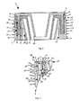
- FIG. 4 and FIG. 5 show a sealing device 100 according to an alternative embodiment.
- the sealing device 100 has a sealing body 103.
- a first sealing cone 119 is formed on an inner peripheral surface 141 of the sealing body 103.
- the first sealing cone is aligned substantially coaxially with the sealing body 103.
- the first sealing cone 119 is arranged completely inside the sealing body 103.
- the sealing device 100 has a second sealing cone 113 and a third sealing cone 133.
- the first sealing cone 119, the second sealing cone 113 and the third sealing cone 133 are lined up coaxially and serially.
- the sealing cones are partially disposed within the sealing body 103.
- the second sealing cone 113 is connected in a predetermined breaking section 120 by means of a predetermined breaking point with the first sealing cone 119.
- the predetermined breaking point has a ring 128, which on both sides by means of predetermined breaking edges 124 with the sealing body 103 on the one hand and the second sealing cone 113 on the other hand is connected.
- the third sealing cone 133 is connected in a predetermined breaking section 122 with the second sealing cone 113.
- the predetermined breaking section 122 has a ring 130, which is connected on both sides by means of predetermined breaking edges 126 to the second sealing cone 113 on the one hand and the third sealing cone 133 on the other hand.
- the sealing body 103, the first sealing cone 119, the second sealing cone 113 and the third sealing cone 133 are arranged coaxially relative to the axis of rotation 132.
- a plurality of recesses 121 is formed on an end face 117.
- the recesses 121 extend into the interior of the sealing body 103 and are adapted to receive correspondingly formed projections.
- the projections are preferably formed on a clamping body (not shown) and adapted to effect an elastic deformation at least in the radial direction of the sealing body 103. Due to the elastic deformation of the sealing body 103, a clamping force is applied in the installed state in the opening of a Bewandsungs-section.
- first and second sealing projections 125, 127 are arranged on the outer peripheral surface 123 of the sealing body 103 .
- the first and second sealing projections 125, 127 are formed in a substantially annular shape and extend radially from the outer peripheral surface 131.
- the first and second sealing projections 125, 127 are arranged alternately and spaced from each other.
Landscapes
- Engineering & Computer Science (AREA)
- General Engineering & Computer Science (AREA)
- Mechanical Engineering (AREA)
- Architecture (AREA)
- Civil Engineering (AREA)
- Structural Engineering (AREA)
- Gasket Seals (AREA)
Abstract
Description
Die vorliegende Erfindung betrifft eine Dichtvorrichtung zur Abdichtung eines Spalts zwischen einer Öffnung in einem Bewandungs-Abschnitt und mindestens einer durch die Öffnung durchgeführten Leitung, mit einem elastisch verformbaren Dichtkörper, der in die Öffnung des Bewandungs-Abschnitts einführbar ist und dazu eingerichtet ist, diese abzudichten.The present invention relates to a sealing device for sealing a gap between an opening in a Verandungsabschnitt and at least one duct performed through the opening, with an elastically deformable sealing body, which is insertable into the opening of the Bewandsungs-section and is adapted to seal them ,
Dichtvorrichtungen der vorstehend genannten Art werden typischerweise dazu eingesetzt, Durchbrüche oder Durchführungsöffnungen in Bewandungs-Abschnitten von Wänden, Decken oder Bodenbereichen abzudichten. Hierbei werden Dichtheitsanforderungen sowohl an die Abdichtung der Dichtvorrichtung gegen die mindestens eine durchgeführte Leitung und an die Abdichtung der Dichtvorrichtung gegen die Öffnung des Bewandungs-Abschnitts gestellt. Die Wand kann beispielsweise eine Gebäude- oder eine Fahrzeugwand sein. Die sogenannten Durchführungsöffnungen findet man üblicherweise dort in Bewandungs-Abschnitten, wo Leitungen über Geschoss- oder Raumgrenzen hinaus zu verlegen sind.Sealing devices of the above-mentioned type are typically used to seal breakthroughs or grommets in walling, ceiling or floor areas of the wall. In this case, sealing requirements are placed both on the sealing of the sealing device against the at least one performed line and on the sealing of the sealing device against the opening of the Bewandungs section. The wall may be, for example, a building or a vehicle wall. The so-called feedthrough openings are usually found there in Bewandungs sections where lines are to be laid beyond floor or floor space.
Es sind im Stand der Technik verschiedene Dichtvorrichtungen bekannt, die zum Abdichten von Leitungs-Einführungen der vorstehenden beschriebenen Art genutzt werden. Den bekannten Dichtvorrichtungen ist gemein, dass die Dichtvorrichtungen mit der durchzuführenden Leitung bzw. den durchzuführenden Leitungen dichtend verbunden werden und sodann samt der Leitung bzw. den Leitungen in die Öffnung des Bewandungs-Abschnitts eingeführt werden. Ziel aller Dichtvorrichtungen ist es, den Raum zwischen der Innenfläche des Bewandungs-Abschnitts und der Dichtvorrichtung dichtend zu verschließen.Various sealing devices are known in the art which have been used to seal conduit entries of the type described above become. The known sealing devices have in common that the sealing devices are sealingly connected to the line to be performed or the lines to be performed and then be introduced together with the line or lines in the opening of the Bewandungs section. The aim of all sealing devices is to seal the space between the inner surface of the Bewandsungsabschnitt and the sealing device.
Dichtvorrichtungen, die für den Einsatz in Bewandungs-Abschnitten vorgesehen sind, in deren Umgebung Wasser steht und einen hydrostatischen Druck aufweisen, müssen zum Aufbringen hoher Dichtkräfte ausgebildet sein, um die anstehende Wassersäule zuverlässig am Durchdringen der Öffnung des Bewandungs-Abschnitts zu hindern. Zum Aufbringen hoher Dichtkräfte ist es notwendig, den Dichtkörper aus einem verhältnismäßig steifen Material auszuführen. Damit einhergehend ergibt sich der Nachteil, dass solche Dichtkörper in der Regel nicht manuell montier- und/oder demontierbar sind, sondern mittels einer Spanneinrichtung in den Bewandungs-Abschnitt eingeführt werden müssen.Sealing devices which are intended for use in Bewandsungsabschnitte, in the vicinity of which is water and have a hydrostatic pressure, must be designed to apply high sealing forces to reliably prevent the upcoming water column at the penetration of the opening of the Bewandsungsabschnitt. To apply high sealing forces, it is necessary to carry out the sealing body of a relatively rigid material. This entails the disadvantage that such sealing bodies are usually not manually assembled and / or disassembled, but must be introduced by means of a clamping device in the Bewandungs section.
Weiterhin sind im Stand der Technik Dichtvorrichtungen bekannt, die manuell in die Öffnung des Bewandungs-Abschnitts einführbar sind und auch manuell demontierbar sind. Ein Nachteil jener bekannten Dichtvorrichtungen ist darin zu sehen, dass aufgrund konstruktiver Merkmale oder aber aufgrund der Auswahl eines verhältnismäßig weichen Materials des Dichtkörpers keine ausreichend hohen Dichtkräfte aufgebracht werden können, so dass die Dichtvorrichtungen lediglich in Abwesenheit von Wasser oder hoher Feuchtigkeit eine zuverlässige Dichtfunktion gewährleisten können.Furthermore, in the prior art sealing devices are known, which are manually inserted into the opening of the Bewandungs section and are also manually disassembled. A disadvantage of those known sealing devices is the fact that due to design features or due to the selection of a relatively soft material of the sealing body, sufficiently high sealing forces can not be applied, so that the sealing devices can ensure a reliable sealing function only in the absence of water or high humidity ,
Die bekannten Dichtvorrichtungen sind typischerweise dazu ausgelegt, Leitungen eines vorbestimmten Durchmessers im Inneren des Dichtkörpers aufzunehmen und dichtend zu führen. In der Praxis ist man allerdings in der Regel mit Leitungen unterschiedlicher Durchmesser konfrontiert. Zum dichtenden Durchführen der jeweiligen Leitungen durch die Öffnung eines Bewandungs-Abschnitts ist es somit notwendig, eine Vielzahl unterschiedlicher Dichtvorrichtungen vorzuhalten, die jeweils für die Durchführung eines bestimmten Leitungsdurchmessers konfektioniert sind. Es besteht somit auch ein Bedarf, die Vielseitigkeit einer Dichtvorrichtung zu verbessern.The known sealing devices are typically designed to receive lines of a predetermined diameter in the interior of the sealing body and to perform sealing. In practice, however, one is usually confronted with lines of different diameters. For sealingly passing the respective lines through the opening of a walling section, it is thus necessary to provide a multiplicity of different sealing devices, each of which is made up to carry out a specific line diameter. There is thus a need to improve the versatility of a sealing device.
Der vorliegenden Erfindung lag folglich die Aufgabe zu Grunde, eine Dichtvorrichtung anzugeben, welche eine verbesserte Handhabbarkeit und eine verbessere Flexibilität hinsichtlich der durchzuführenden Leitungen gewährleistet.The present invention was therefore based on the object to provide a sealing device which ensures improved handling and flexibility with respect to the lines to be performed.
Die Erfindung löst die ihr zu Grunde liegende Aufgabe bei einer Dichtvorrichtung der eingangs genannten Art, indem ein oder mehrere Dichtkonen koaxial zu dem Dichtkörper ausgerichtet und überlappend angeordnet sind, wobei der oder die Dichtkonen mittels einer reversibel lösbaren Verbindung mit dem Dichtkörper verbindbar sind. Vorzugsweise ist die reversibel lösbare Verbindung als Steckverbindung ausgebildet.The invention solves the underlying task in a sealing device of the type mentioned by one or more sealing cones are aligned coaxially with the sealing body and arranged overlapping, wherein the or the sealing cones are connected by means of a reversibly releasable connection to the sealing body. Preferably, the reversibly releasable connection is designed as a plug connection.
Die Erfindung beruht auf der Erkenntnis, dass die Verwendung eines oder mehrerer reversibel lösbar mit dem Dichtkörper verbundene Dichtkonen den Monteur in die Lage versetzt, eine Dichtvorrichtung mit immer dem selben Dichtkörper zu verwenden und in die Öffnung des Bewandungs-Abschnitts einzusetzen, und den Dichtkonus, welcher dichtend mit der Leitung zu verbinden ist, je nach Durchmesser der durchzuführenden Leitung passend auszuwählen und sodann mit dem Dichtkörper zu verbinden. Die Dichtvorrichtung stellt sich somit als modulares Baukastensystem dar, welches auch nachträglich einen Austausch lediglich des Dichtkonus ermöglicht, falls die durchgeführte Leitung ausgetauscht und gegen eine neue Leitung mit verändertem Durchmesser ersetzt werden muss.The invention is based on the finding that the use of one or more sealing cones connected in a reversibly detachable manner to the sealing body enables the installer to use a sealing device with always the same sealing body and to insert it into the opening of the sanding section, and the sealing cone, which is sealingly connected to the line, depending on the diameter of the line to be performed to select suitable and then to connect to the sealing body. The sealing device thus presents itself as a modular system, which also subsequently allows an exchange only of the sealing cone, if the performed lead exchanged and replaced with a new line with a different diameter.
Die vorzugsweise als Steckverbindung ausgebildete reversibel lösbare Verbindung zwischen Dichtkonus bzw. Dichtkonen und Dichtkörper bringt den Vorteil mit sich, dass sie in der Regel ohne Werkzeug hergestellt und gelöst werden kann. Unter einer reversiblen Lösbarkeit wird hierbei die Eignung verstanden, zerstörungsfrei eine Lösung und vorzugsweise eine erneute Verbindung herbeizuführen, und dies vorzugsweise beliebig oft zu wiederholen.The preferably designed as a plug connection reversibly releasable connection between the sealing cone or sealing cones and sealing body has the advantage that it can be prepared and solved usually without tools. A reversible solubility here means the ability to bring about a non-destructive solution and preferably a renewed connection, and preferably to repeat this as often as desired.
Ein weiterer besonderer Vorteil zeigt sich darin, dass innerhalb des Dichtkörpers eine Mehrzahl von Dichtkonen koaxial untereinander überlappend angeordnet werden. Der Monteur muss in einer solchen Ausführung lediglich jene Dichtkonen entfernen, die einen unpassenden Innendurchmesser zur Aufnahme der durchzuführenden Leitung aufweisen. Diese Dichtkonen können als Standard-Teile vorgehalten werden. Folglich ist der Bevorratungsaufwand im Vergleich zu einer Lösung, in der die komplette Dichtvorrichtung vorgehalten werden muss, deutlich verringert.Another particular advantage is that within the sealing body a plurality of sealing cones are arranged coaxially overlapping one another. In such an embodiment, the installer only has to remove those sealing cones which have an inappropriate inner diameter for receiving the line to be carried out. These sealing cones can be kept as standard parts. Consequently, the storage cost is significantly reduced compared to a solution in which the complete sealing device must be kept.
Gemäß einer bevorzugten Ausführungsform der vorliegenden Erfindung ist ein erster Dichtkonus an einer inneren Umfangsfläche des Dichtkörpers ausgebildet. Im Sinne einer Reduzierung der Bauteilanzahl der Dichtvorrichtung ist es vorteilhaft, einen Dichtkonus fest mit dem Dichtkörper zu verbinden und an einer inneren Umfangsfläche des Dichtkörpers anzuordnen. Dieser Dichtkonus ist vorzugsweise derjenige, welcher zur Aufnahme der größten anzunehmenden durchzuführenden Leitung eingerichtet ist. Optional sind weitere Dichtkonen zwiebelschalenartig und reversibel lösbar zu dem ersten Dichtkonus hin innerhalb des Dichtkörpers anzuordnen. Gemäß der vorstehenden Ausführungsform sind der Dichtkörper und der erste Dichtkonus einstückig als ein Bauteil ausgeführt. Alternativ wird es auch als vorteilhaft angesehen, den Dichtkörper als ein Bauteil auszuführen und den ersten Dichtkonus als separates Bauteil, welches mittels einer reversibel lösbaren Verbindung mit dem Dichtkörper verbindbar ist.According to a preferred embodiment of the present invention, a first sealing cone is formed on an inner peripheral surface of the sealing body. In terms of reducing the number of components of the sealing device, it is advantageous to connect a sealing cone fixed to the sealing body and to arrange on an inner peripheral surface of the sealing body. This sealing cone is preferably the one which is set up to accommodate the largest lead to be taken. Optionally, further sealing cones are to be arranged on the inside of the sealing body on a bulbous and reversibly releasable manner relative to the first sealing cone. According to the above embodiment, the sealing body and the first sealing cone are integrally formed as a component. Alternatively, it is also considered advantageous to carry out the sealing body as a component and the first sealing cone as a separate component, which is connectable by means of a reversibly releasable connection with the sealing body.
Gemäß einer bevorzugten Ausführungsform ist ein zweiter Dichtkonus als separates Bauteil ausgebildet und weist eine Stirnseite auf, an welcher ein flanschartiger Vorsprung ausgebildet ist, der mit einer Stirnseite des Dichtkörpers korrespondiert. Eine Ausführung bereits des zweiten Dichtkonus als separates Bauteil erhöht die Flexibilität der Dichtvorrichtung. Der Dichtkörper ist universell für jegliche Arten von Durchführungsleitung einsetzbar, da der zweite Dichtkonus und optional weitere Dichtkonen modular mit dem Dichtkörper verbindbar und von ihm lösbar ist. Der flanschartige Vorsprung des Dichtkonus ist in montiertem Zustand des Dichtkonus relativ zum Dichtkörper in Anlage mit der korrespondierenden Fläche der Stirnseite des Dichtkörpers.According to a preferred embodiment, a second sealing cone is formed as a separate component and has an end face on which a flange-like projection is formed, which corresponds to an end face of the sealing body. An embodiment already of the second sealing cone as a separate component increases the flexibility of the sealing device. The sealing body can be universally used for any type of feedthrough line, since the second sealing cone and optionally further sealing cones can be modularly connected to the sealing body and detachable from it. The flange-like projection of the sealing cone is in the assembled state of the sealing cone relative to the sealing body in contact with the corresponding surface of the end face of the sealing body.
In einer weiteren bevorzugten Ausführungsform der Dichtvorrichtung erstrecken sich von dem flanschartigen Vorsprung des zweiten Dichtkonus ein Vorsprung oder mehrere Vorsprünge, welche jeweils mit einer Ausnehmung in der Stirnseite des Dichtkörpers korrespondieren. Die Vorsprünge, welche sich von dem flanschartigen Vorsprung aus erstrecken, sind mit der korrespondierenden Ausnehmung in der Stirnseite des Dichtkörpers vorzugsweise formschlüssig in Eingriff bringbar. Die Vorsprünge sind insbesondere dazu eingerichtet, als Verdrehsicherung zu wirken und den Dichtkonus relativ zu der Stirnseite zu positionieren.In a further preferred embodiment of the sealing device extending from the flange-like projection of the second sealing cone, a projection or a plurality of projections, which correspond in each case with a recess in the end face of the sealing body. The projections, which extend from the flange-like projection, can preferably be brought into positive engagement with the corresponding recess in the end face of the sealing body. The projections are in particular adapted to act as anti-rotation and to position the sealing cone relative to the end face.
Die erfindungsgemäße Dichtvorrichtung wird vorzugsweise dadurch weitergebildet, dass ein dritter Dichtkonus als separates Bauteil ausgebildet ist und eine Stirnseite aufweist, in welcher ein flanschartiger Vorsprung ausgebildet ist, der mit einer Stirnseite des Dichtkörpers und/oder mit einer Stirnseite des zweiten Dichtkonus korrespondiert. Vorzugsweise erstrecken sich von dem flanschartigen Vorsprung, der an dem dritten Dichtkonus ausgebildet ist, ein Vorsprung oder mehrere Vorsprünge fort, welche jeweils mit einer Ausnehmung in der Stirnseite des zweiten Dichtkonus und/oder in der Stirnseite des Dichtkörpers korrespondieren. Auf diese Weise ergibt sich ein Stecksystem, mittels dessen mehrere Dichtkonen ineinander und in den Dichtkörper steckbar sind. Gleichzeitig sind alle ineinander einführbaren Teile relativ zueinander mit hoher Wiederholgenauigkeit positionierbar.The sealing device according to the invention is preferably further developed in that a third sealing cone is formed as a separate component and has an end face in which a flange-like projection is formed, which corresponds to an end face of the sealing body and / or with an end face of the second sealing cone. Preferably, one or more projections extend from the flange-like projection formed on the third sealing cone, each corresponding to a recess in the end face of the second sealing cone and / or in the end face of the sealing body. In this way, a plug-in system, by means of which a plurality of sealing cones are plugged into each other and into the sealing body results. At the same time, all parts which can be inserted into one another can be positioned relative to one another with high repeatability.
Vorzugsweise sind der oder die sich von dem flanschartigen Vorsprung des zweiten Dichtkonus aus erstreckenden Vorsprünge zur Verformung des Dichtkörpers in die Ausnehmungen in der Stirnseite des Dichtkörpers einführbar, und/oder der oder die sich von dem flanschartigen Vorsprung des dritten Dichtkonus aus erstreckenden Vorsprünge zur Verformung des Dichtkörpers in die Ausnehmungen in der Stirnseite des Dichtkörpers oder in die Ausnehmungen in der Stirnseite des zweiten Dichtkonsus einführbar. Aus dieser Ausführung ergibt sich ein besonderer Vorteil der vorliegenden Erfindung. Der Vorteil beruht auf der Erkenntnis, dass die sich von dem ersten und/oder zweiten Dichtkonus und optional von weiteren Dichtkonen aus erstreckenden Vorsprünge eine elastische Verformung des Dichtkörpers zumindest teilweise in radialer Richtung hervorrufen, wenn die Vorsprünge in die korrespondierenden Ausnehmungen in dem Dichtkörper eingeführt werden. Infolge der elastischen Verformung des Dichtkörpers wird eine Rückstellkraft ausgebildet, die eine Rückformung des Dichtkörpers in seinen ursprünglichen Zustand bewirkt, sobald die Vorsprünge mit den korrespondierenden Ausnehmungen außer Eingriff geraten. In Folge der elastischen Verformung wird folglich die Klemmkraft erhöht, die zwischen dem Dichtkörper und den Dichtkonen einerseits und dem Dichtkörper und der Öffnung des Bewandungs-Abschnitts andererseits wirkt. Die Vorsprünge wirken nach Art eines Klemmkeils. Infolgedessen ist es möglich, den Dichtkörper aus einem verhältnismäßig weichen Material herzustellen und von Hand, ohne weitere Montagehilfsmittel wie beispielsweise Spanvorrichtungen, in die Öffnung des Bewandungs-Abschnitts einzuführen. Die Dichtkraft wird sukzessive erhöht oder alternativ überhaupt erst aufgebracht, wenn die Vorsprünge von den flanschartigen Vorsprüngen der Dichtkonen in die korrespondierenden Ausnehmungen im Dichtkörper eingreifen. Je nach Größe und Übermaß des Vorsprungs relativ zu der korrespondierenden Ausnehmung ist die Stärke der aufgebrachten Klemmkraft gezielt beeinflussbar. Überdies ergibt sich hieraus der Vorteil, dass die äußere Abmessung des Dichtkörpers eine höhere Toleranz relativ zu der Öffnung in dem Bewandungs-Abschnitt aufweisen kann, da auf Grund des weicheren Materials ein größerer Toleranzbereich mit noch zufriedenstellender Dichtwirkung abgedeckt wird. Die Vorsprünge, die sich von den flanschartigen Vorsprüngen des bzw. der Dichtkonen fort erstrecken, wirken somit gleichzeitig als Klemmelemente und als Positionierhilfen für die Dichtkonen relativ zum Dichtkörper der Dichtvorrichtung.Preferably, the one or more projections extending from the flange-like projection of the second sealing cone for deforming the sealing body are insertable into the recesses in the end face of the sealing body, and / or the projection or projections extending from the flange-like projection of the third sealing cone for deforming Sealing body inserted into the recesses in the end face of the sealing body or in the recesses in the end face of the second Dichtkonsus. From this embodiment, there is a particular advantage of the present invention. The advantage is based on the knowledge that the protrusions extending from the first and / or second sealing cone and optionally from further sealing cones cause elastic deformation of the sealing body at least partially in the radial direction when the projections are inserted into the corresponding recesses in the sealing body , As a result of the elastic deformation of the sealing body, a restoring force is formed, which causes a recovery of the sealing body in its original state as soon as the projections with the corresponding recesses disengage. As a result of the elastic deformation consequently the clamping force is increased, which acts between the sealing body and the sealing cones on the one hand and the sealing body and the opening of the Bewandungs section on the other. The projections act in the manner of a clamping wedge. As a result, it is possible to make the sealing body from a relatively soft material and to insert by hand, without further assembly aids such as chip devices, in the opening of the Bewandsungs-section. The sealing force is successively increased or alternatively only applied when the projections of the flange-like projections of the sealing cones engage in the corresponding recesses in the sealing body. Depending on the size and excess of the projection relative to the corresponding recess, the strength of the applied clamping force can be selectively influenced. Moreover, this results in the advantage that the outer dimension of the sealing body may have a higher tolerance relative to the opening in the Bewandungs section, as due to the softer material with a larger tolerance range satisfactory sealing effect is covered. The projections which extend away from the flange-like projections of the sealing cone or cones, thus act simultaneously as clamping elements and as positioning aids for the sealing cones relative to the sealing body of the sealing device.
Gemäß einer weiteren bevorzugten Ausführungsform der erfindungsgemäßen Dichtvorrichtung weist jeder Dichtkonus einen konischen Dicht-Abschnitt auf, dessen lichte Weite partiell geringer als der äußere Durchmesser der durchzuführenden Leitung ist. Der konische Dichtabschnitt wird infolge der Durchführung der durchzuführenden Leitung jedenfalls in dem Bereich, dessen lichte Weite geringer als der äußere Durchmesser der durchzuführenden Leitung ist, gedehnt. Infolge der Dehnung stellt sich auch zwischen der durchgeführten Leitung und den konischen Dicht-Abschnitten aufgrund der elastischen Verformung des letzteren eine Dichtkraft und folglich Dichtwirkung ein. Die Höhe der Dichtkraft ist gezielt beeinflussbar, indem das Übermaß der Leitung relativ zum konischen Abschnitt des Dichtkonus entsprechend gewählt wird, oder mittels der Härte bzw. Elastizität des konischen Dicht- Abschnitts.According to a further preferred embodiment of the sealing device according to the invention, each sealing cone has a conical sealing section whose inside width is partially smaller than the outer diameter of the line to be performed. The conical sealing portion is stretched due to the implementation of the line to be performed at least in the area whose inside diameter is less than the outer diameter of the line to be performed. As a result of the expansion, a sealing force and, consequently, a sealing effect also arise between the duct that has been made and the conical sealing sections due to the elastic deformation of the latter. The height of the sealing force can be selectively influenced by the excess of the conduit is chosen according to the conical portion of the sealing cone, or by means of the hardness or elasticity of the conical sealing portion.
Vorzugsweise ist der konische Abschnitt der Dichtkonen elastisch stärker verformbar als der Rest der Dichtkonen. Die Vorsprünge, die sich von den flanschartigen Vorsprüngen der Dichtkonen aus erstrecken, sind vorzugsweise aus einem harten Material ausgeführt, während der konische Abschnitt des Dichtkonus vorzugsweise aus einem weichen und elastisch mit geringerem Kraftaufwand verformbaren Material ausgebildet ist. Dies betrifft sowohl Ausführungsformen, in welchen der Dichtkonus ein separates Bauteil ist als auch jene Ausführungsformen, in denen der Dichtkonus einstückig mit dem Dichtkörper ausgebildet ist. In letztgenanntem Fall besteht der Dichtkonus, insbesondere der erste Dichtkonus, ausschließlich aus dem konischen Abschnitt.Preferably, the conical section of the sealing cones is elastically more deformable than the rest of the sealing cones. The projections which extend from the flange-like projections of the sealing cones are preferably made of a hard material, while the conical portion of the sealing cone is preferably formed of a soft and elastically deformable with less force material. This applies both to embodiments in which the sealing cone is a separate component as well as those embodiments in which the sealing cone is formed integrally with the sealing body. In the latter case, the sealing cone, in particular the first sealing cone, consists exclusively of the conical section.
Der Dichtkörper weist gemäß einer bevorzugten Ausführungsform eine äußere Umfangsfläche auf, an welcher mehrere Dichtvorsprünge ausgebildet und in Umfangsrichtung und/oder axial ausgerichtet sind. Die Dichtvorsprünge sind vorzugsweise als Lamellen ausgebildet, die im Wesentlichen ringförmig entlang der äußeren Umfangsfläche verteilt sind und zueinander axial beabstandet sind. Die Dichtvorsprünge können sich im Wesentlichen radial von der äußeren Umfangsfläche aus fort erstrecken, oder in einem Winkel schräg zu der äußeren Umfangsfläche angeordnet sein. Schräg angeordnete Dichtvorsprünge bzw. Dichtlamellen weisen eine erhöhte Widerstandskraft gegen Entfernen des Dichtkörpers aus der Öffnung des Bewandungs-Abschnitts auf, vergleichbar mit einem Widerhaken.The sealing body has, according to a preferred embodiment, an outer peripheral surface on which a plurality of sealing projections are formed and aligned in the circumferential direction and / or axially. The sealing projections are preferably formed as lamellae, which are distributed substantially annularly along the outer peripheral surface and are axially spaced from each other. The sealing projections may extend substantially radially from the outer peripheral surface, or may be disposed at an angle oblique to the outer peripheral surface. Obliquely arranged sealing projections or sealing lamellae have an increased Resistance to removal of the sealing body from the opening of the Bewands section on, comparable to a barb.
Die erfindungsgemäße Dichtvorrichtung wird weitergebildet durch einen im Wesentlichen ringförmigen Klemmkörper mit einer Stirnseite und sich von der Stirnseite aus erstreckenden Vorsprüngen, die zur Verformung des Dichtkörpers und/oder mindestens eines der Dichtkonen in korrespondierende Ausnehmungen in der Stirnseite des Dichtkörpers und/oder der Stirnseite des mindestens Einen der Dichtkonen einführbar sind. Der im Wesentlichen ringförmige Klemmkörper ist vorzugsweise ein Klemmelement, welches mit den sich von dessen Stirnseite aus erstreckenden Vorsprüngen formschlüssig mit dem Dichtkörper bzw. dessen korrespondierenden Ausnehmungen in Eingriff bringbar ist. Für den Fall, dass mittels der Vorsprünge selbst keine Klemmkraft durch elastische Verformung des Dichtkörpers aufgebracht werden soll oder kann, ist der Klemmkörper zum Aufbringen der zur Abdichtung benötigten Klemmkraft eingerichtet.The sealing device according to the invention is further developed by a substantially annular clamping body with an end face and extending from the front side protrusions, for the deformation of the sealing body and / or at least one of the sealing cones in corresponding recesses in the end face of the sealing body and / or the end face of at least One of the sealing cones are insertable. The substantially annular clamping body is preferably a clamping element, which can be brought into positive engagement with the projections extending from its end face with the sealing body or its corresponding recesses. In the event that by means of the projections itself no clamping force to be applied by elastic deformation of the sealing body or can, the clamping body is adapted to apply the clamping force required for sealing.
Der Klemmkörper ist vorzugsweise mehrteilig, insbesondere zweiteilig ausgebildet und weist eine entsprechende Anzahl Teilkörper auf. Die mehrteilige Ausführung des Klemmkörpers ermöglicht ein Einführen der Leitung und des Dichtkörpers in die Öffnung des Bewandungs- Abschnitts, bevor der Klemmkörper über die durchzuführende Leitung gestülpt worden sein muss. Der mehrteilige Klemmkörper kann vielmehr erst nach Montage des Dichtkörpers und Durchführung der Leitung mit dem Dichtkörper in Verbindung gebracht werden, um sodann die notwendige Klemm- und Dichtkraft aufzubringen. Es können verschiedene Ausführungen des Klemmkörpers vorgehalten werden, die sich in der Größe der als Klemmkeil dienenden Vorsprünge voneinander unterscheiden und jeweils zum Aufbringen einer voneinander unterschiedlichen Klemmkraft ausgebildet sind. Vorzugsweise sind die unterschiedlichen Klemmkörper farblich voneinander unterscheidbar gekennzeichnet, sodass ein Auswählen des korrekten Klemmkörpers für den Monteur erleichtert ist.The clamping body is preferably multi-part, in particular formed in two parts and has a corresponding number of partial body. The multi-part design of the clamp body allows insertion of the line and the sealing body in the opening of the Bewandungs- section before the clamp body must have been slipped over the line to be performed. The multipart clamping body can be brought into connection only after installation of the sealing body and passage of the line to the sealing body, in order to then apply the necessary clamping and sealing force. Various embodiments of the clamping body can be kept in reserve, which differ from each other in the size of the projections serving as a clamping wedge and are each designed to apply a mutually different clamping force. Preferably, the different sprags are color coded distinguishable from each other, so that a selection of the correct clamp body is easier for the installer.
Gemäß einer weiteren bevorzugten Ausführungsform weist die Dichtvorrichtung mehrere Gruppen von Dichtkonen auf, wobei die Dichtkonen innerhalb einer Gruppe jeweils koaxial innerhalb des Umfangs des Dichtkörpers angeordnet sind, und die Gruppen zueinander parallel ausgerichtet sind. Durch das Vorsehen mehrerer Gruppen von Dichtkonen sind mehrere Leitungen gleichzeitig und im Wesentlichen parallel zueinander durch den Dichtkörper und somit durch die Öffnung des Bewandungs-Abschnitts hindurch führbar. Jeder der Dichtkonen ist vorzugsweise gemäß einer der vorstehend dargestellten bevorzugten Ausführungsformen der erfindungsgemäßen Dichtvorrichtung ausgebildet.According to a further preferred embodiment, the sealing device has a plurality of groups of sealing cones, wherein the sealing cones within a group are each arranged coaxially within the circumference of the sealing body, and the groups are aligned parallel to each other. By providing a plurality of groups of sealing cones, a plurality of lines are simultaneously and substantially parallel to one another through the sealing body and thus through the opening of the Bewandungs section feasible. Each of the sealing cones is preferably designed according to one of the above-described preferred embodiments of the sealing device according to the invention.
Ein weiteres Ausführungsbeispiel einer Dichtvorrichtung sieht vor, dass die Dichtvorrichtung eine Mehrzahl Dichtkonen aufweist, welche mindestens teilweise innerhalb des Dichtkörpers angeordnet sind und koaxial zu dem Dichtkörper ausgerichtet und seriell aneinander gereiht sind. Vorzugsweise weist jede Dichtvorrichtung einen ersten Dichtkonus auf, der an einer inneren Umfangsfläche des Dichtkörpers ausgebildet ist und einen zweiten Dichtkonus, welcher mittels einer Sollbruchstelle mit dem ersten Dichtkonus verbunden ist.Another embodiment of a sealing device provides that the sealing device has a plurality of sealing cones, which are arranged at least partially within the sealing body and are aligned coaxially to the sealing body and serially lined up. Preferably, each sealing device has a first sealing cone, which is formed on an inner peripheral surface of the sealing body and a second sealing cone, which is connected by means of a predetermined breaking point with the first sealing cone.
Die Dichtvorrichtung weist weiter vorzugsweise einen oder mehrere dritte Dichtkonen auf, die jeweils mittels einer Sollbruchstelle mit dem oder den jeweils benachbarten Dichtkonen verbunden sind.The sealing device further preferably has one or more third sealing cones, which are each connected by means of a predetermined breaking point with the or each adjacent sealing cones.
Die Erfindung wird vorliegend anhand einer Vorrichtung beschrieben, welche einen ersten Dichtkonus, sowie einen zweiten und einen dritten Dichtkonus aufweist. Alternative, bevorzugte Ausführungsformen weisen darüberhinaus eine Dichtvorrichtung auf, die beispielsweise vierte, fünfte, sechste, siebte, achte, neunte, oder zehnte Dichtkonen aufweist. Diese weiteren Dichtkonen sind in analoger Weise wie die vorstehend erläuterten zweiten oder dritten Dichtkonen ausgebildet, weshalb auf die vorstehenden Erläuterungen hierzu verwiesen wird.In the present case, the invention will be described with reference to a device which has a first sealing cone as well as a second and a third sealing cone. Alternative, preferred embodiments also have a sealing device, which has, for example, fourth, fifth, sixth, seventh, eighth, ninth, or tenth sealing cones. These further sealing cones are formed in an analogous manner as the second or third sealing cones explained above, for which reason reference is made to the above explanations.
Gemäß einer weiteren alternativen Ausführungsform der Erfindung weist die erfindungsgemäße Dichtvorrichtung beispielsweise zwei, drei, vier, fünf, sechs, sieben, acht, neun oder zehn Gruppen von Dichtkonen auf, wobei die Dichtkonen innerhalb einer Gruppe jeweils koaxial innerhalb des Umfangs des Dichtköpers angeordnet sind, und die Gruppen zueinander im Wesentlichen parallel ausgerichtet sind. Je nachdem, wie viele Leitungen parallel durch die Öffnung des Bewandungsabschnitts durchgeführt werden sollen, wird eine entsprechende Dichtvorrichtung mit passender Anzahl Dichtkonen-Gruppen ausgewählt. Überflüssige - d.h. nicht benutzte Gruppen von Dichtkonen für die Durchführung von Leitungen sind vorzugsweise mittels eines reversibel lösbaren Verschlusselements dichtend verschließbar. Ein solches Verschlusselement ist beispielsweise bevorzugt als zylindrisch ausgebildeter Blindstopfen ausgeführt.According to a further alternative embodiment of the invention, the sealing device according to the invention, for example, two, three, four, five, six, seven, eight, nine or ten groups of sealing cones, wherein the sealing cones are arranged within a group respectively coaxially within the circumference of the Dichtköpers, and the groups are aligned substantially parallel to each other. Depending on how many lines are to be performed in parallel through the opening of the Bewandungsabschnitts, a corresponding sealing device is selected with a suitable number of Dichtkonen groups. Superfluous - ie unused groups of sealing cones for the passage of lines are preferably sealingly closed by means of a reversibly releasable closure element. Such a closure element is for example preferably designed as a cylindrically designed blind stopper.
Die Erfindung wird im Folgenden anhand bevorzugter Ausführungsbeispiele und unter Bezugnahme auf die beigefügten Figuren näher erläutert. Hierbei zeigen:
Figur 1- eine Explosionsdarstellung der erfindungsgemäßen Dichtvorrichtung gemäß eines ersten Ausführungsbeispiels,
- Figur 2
- eine Querschnittsansicht der erfindungsgemäßen Dichtvorrichtung gemäß dem ersten Ausführungsbeispiel,
Figur 3- eine Querschnittsansicht eines Ausbruchs der erfindungsgemäßen Dichtvorrichtung gemäß einem zweiten Ausführungsbeispiel,
- Figur 4
- eine Querschnittsansicht der erfindungsgemäßen Dichtvorrichtung gemäß einem dritten Ausführungsbeispiel, und
Figur 5- eine Draufsicht auf die Dichtvorrichtung gemäß dem in
Figur 4 gezeigten Ausführungsbeispiel.
- FIG. 1
- an exploded view of the sealing device according to the invention according to a first embodiment,
- FIG. 2
- a cross-sectional view of the sealing device according to the invention according to the first embodiment,
- FIG. 3
- a cross-sectional view of an outbreak of the sealing device according to the invention according to a second embodiment,
- FIG. 4
- a cross-sectional view of the sealing device according to the invention according to a third embodiment, and
- FIG. 5
- a plan view of the sealing device according to the in
FIG. 4 shown embodiment.
In
Der Dichtkörper 3 weist eine Vielzahl von Ausnehmungen 21 auf, die sich von einer Stirnseite 17 des Dichtkörpers 3 aus in das Innere des Dichtkörpers 3 erstrecken. Der Dichtkörper 3 weist an einer äußeren Umfangsfläche 23 eine Vielzahl von ersten Dichtvorsprüngen 25 und zweiten Dichtvorsprüngen 27 auf. Die ersten und zweiten Dichtvorsprünge 25, 27 sind im Wesentlichen ringförmig an der äußeren Umfangsfläche 23 des Dichtkörpers 3 angeordnet und erstrecken sich im Wesentlichen in radialer Richtung. Die ersten Dichtvorsprünge 25 sind im Verhältnis zu den zweiten Dichtvorsprüngen 27 kürzer ausgebildet und weisen die gleiche Materialstärke auf wie die zweiten Dichtvorsprünge 27. Alternativ können die ersten und zweiten Dichtvorsprünge 25, 27 mit unterschiedlichen Materialstärken ausgebildet sein, so dass die ersten und zweiten Dichtvorsprünge 25, 27 eine voneinander abweichende Biegesteifigkeit aufweisen. In einer weiteren alternativen Ausführung können die ersten und zweiten Dichtvorsprünge 25, 27 relativ zu der äußeren Umfangsfläche 23 in einem schrägen Winkel angeordnet sein.The sealing
Der zweite Dichtkonus 5 weist an einer Stirnseite 9 einen flanschartigen Vorsprung 11 auf. Von dem flanschartigen Vorsprung 11 aus erstreckt sich eine Vielzahl von Vorsprüngen 15 im Wesentlichen parallel zueinander. Der zweite Dichtkonus 5 weist einen konischen Abschnitt 13 auf. Die Vorsprünge 15 des zweiten Dichtkonus 5 sind im Wesentlichen gleichmäßig entlang des Umfangs des flanschartigen Vorsprungs 11 um den konischen Abschnitt 13 herum verteilt. Von der Stirnseite 9 des zweiten Dichtkonus 5 aus erstrecken sich mehrere Ausnehmungen 16 durch den flanschartigen Vorsprung 11 hindurch. Die Ausnehmungen 16 sind vorzugsweise korrespondierend zu den Vorsprüngen 15 ausgebildet und erstrecken sich vorzugsweise innerhalb der Vorsprünge 15. Die Vorsprünge 15 sind somit vorzugsweise zumindest teilweise als Hohlkörper ausgebildet.The
Der dritte Dichtkonus 7 weist an einer Stirnseite 29 einen flanschartigen Vorsprung 31 auf. Eine Vielzahl von Vorsprüngen 37 erstreckt sich im Wesentlichen parallel zueinander von dem flanschartigen Vorsprung 31 aus. Der dritte Dichtkonus 7 weist einen konischen Abschnitt 33 auf.The third sealing cone 7 has a flange-
Anhand der Darstellung von
Für den Fall, dass nicht der an dem Dichtkörper 3 ausgebildete erste Dichtkonus 19 den angemessenen Durchmesser aufweist, sondern ein kleinerer Durchmesser zum Durchführen der Leitung erforderlich ist, wird der zweite Dichtkonus 5, der als separates Bauteil ausgebildet ist, mit dem konischen Abschnitt 13 über die durchzuführende Leitung gestülpt. Sodann wird der zweite Dichtkonus 5 mit dem Dichtkörper 3 in Eingriff gebracht, indem die Vorsprünge 15 in die korrespondierend ausgebildeten Ausnehmungen 21 des Dichtkörpers 3 eingeführt werden. Vorzugsweise bewirken die Vorsprünge 15 eine elastische Verformung des Dichtkörpers 3 zumindest in radialer Richtung. Dies ist insbesondere der Fall, wenn die Dicke der Vorsprünge 15 zumindest partial größer ist als die entsprechende Abmessung der korrespondierenden Ausnehmung 21. Um ein Einführen der Vorsprünge 15 in die Ausnehmungen 21 zu erleichtern, sind die Vorsprünge 15 an einem zu dem flanschartigen Vorsprung 11 distalen Ende vorzugsweise verjüngt ausgebildet und weisen dort zumindest partial eine geringere Dicke auf als die Ausnehmungen 21 in dem stirnseitigen Abschnitt 17. Alternativ sind die Vorsprünge 15 insgesamt dünner ausgeführt als die Ausnehmungen 21, um ein Einführen des zweiten Dichtkonus 5 in den Dichtkörper 3 zu erleichtern. Die zur Abdichtung erforderliche Klemmkraft wird sodann wie zuvor beschrieben mittels eines Klemmkörpers aufgebracht, welcher Vorsprünge aufweist, die mit den korrespondierend ausgebildeten Ausnehmungen 16 im zweiten Dichtkonus 5 in Eingriff bringbar sind.In the event that not formed on the sealing
Alternativ zu der vorstehend beschriebenen Vorgehensweise wird der zweite Dichtkonus 5 mit dem Dichtkörper 3 in Eingriff gebracht und mit dem flanschartigen Vorsprung 11 in Anlage an die Stirnseite 17 des Dichtkörpers 3 gebracht, bevor die Leitung durch den konischen Abschnitt 13 des zweiten Dichtkonus 5 durchgeführt wird.As an alternative to the procedure described above, the
In Entsprechung zu der Montage des zweiten Dichtkonus 5 wird auch der dritte Dichtkonus 7 erforderlichenfalls entweder vor Einführen der Leitung in den konischen Abschnitt 33 oder danach mit dem Rest der Dichtvorrichtung 1 in Eingriff gebracht. Vorzugsweise wird der dritte Dichtkonus 7 mit dem zweiten Dichtkonus 5 in Eingriff gebracht. In eingebautem Zustand erstrecken sich die sich von dem flanschartigen Vorsprung 31 aus erstreckenden Vorsprünge 35 des dritten Dichtkonus 7 vollständig innerhalb der korrespondierend ausgebildeten Ausnehmung 16 in dem zweiten Dichtkonus 5. Die Vorsprünge 35 sind vorzugsweise dazu ausgebildet, eine elastische Verformung des zweiten Dichtkonus 5 oder optional zumindest der Vorsprünge 15 des zweiten Dichtkonus 5 zu bewirken, wodurch wiederum eine elastische Verformung des Dichtkörpers 3 bewirkt wird. Die Vorsprünge 35 sind vorzugsweise keilförmig ausgebildet, um das Einführen in den zweiten Dichtkonus 5 zu erleichtern und/oder das Aufbringen der Klemmkraft zu verbessern. An einem zu dem flanschartigen Vorsprung 31 distalen Ende sind die Vorsprünge 35 vorzugsweise verjüngt ausgebildet. Insoweit gilt das gleiche wie für die Vorsprünge 15 des zweiten Dichtkonus 5 und deren Zusammenspiel mit den korrespondierend ausgebildeten Ausbildungen 21 des Dichtkörpers 3.Corresponding to the mounting of the
Der vorstehend erwähnte Klemmkörper ist vorzugsweise ähnlich ausgebildet wie der dritte Dichtkonus 7, mit der Ausnahme, dass anstelle eines konischen Abschnitts 33 lediglich eine Durchgangsbohrung vorgesehen ist. Die Durchgangsbohrung weist optional an einer inneren Umfangsfläche eine Dichtlippe auf, die zur Aufnahme der durchzuführenden Leitung eingerichtet ist und zum Schutz gegen das Eindringen von Verschmutzungen und/oder Feuchtigkeit ausgebildet ist.The above-mentioned clamping body is preferably formed similar to the third sealing cone 7, with the exception that instead of a
In
An der Stirnseite 9 des zweiten Dichtkonus 5 befindet sich der flanschartige Vorsprung 31 des dritten Dichtkonus 7 in Anlage mit dem zweiten Dichtkonus 5. Die Vorsprünge 35 des dritten Dichtkonus 7 sind vollständig innerhalb der Ausnehmungen 16 des zweiten Dichtkonus 5 angeordnet. Es ist kein Spalt zwischen den Vorsprüngen 35 und den Ausnehmungen 16 ausgebildet. Die Vorsprünge 35 sind vorzugsweise dazu ausgebildet, eine elastische Verformung des zweiten Dichtkonus 5 zumindest in radialer Richtung zu bewirken, wodurch zumindest der äußere Spalt 39 und optional auch der innere Spalt 37 innerhalb der Ausnehmung 21 des Dichtkörpers 3 zumindest teilweise geschlossen wird. Weiterhin ist festzustellen, dass der Dichtkörper 3 dazu eingerichtet ist, sich beim Einführen in die Öffnung eines Bewandungs-Abschnitts bereits elastisch zu verformen, und zwar derart, dass der äußere Umfang der Umfangsfläche 23 in radialer Richtung abnimmt, sodass in eingebautem Zustand auch der Spalt 39 vermindert oder vollständig geschlossen wird.At the end face 9 of the
In
Die flanschartigen Vorsprünge 11, 31 des zweiten Dichtkonus 5 und des dritten Dichtkonus 7 schließen im Wesentlichen bündig mit der äußeren Umfangsfläche 23 des Dichtkörpers 3 ab.The flange-
In
Eine alternative Ausführung der erfindungsgemäßen Dichtvorrichtung ist in
Im Unterschied zu der in
Der dritte Dichtkonus 7 weist einen im Wesentlichen ringförmig ausgebildeten Vorsprung 35' auf, welcher sich von dem flanschartigen Vorsprung 31 aus erstreckt und im dargestellten, eingebauten Zustand vollständig innerhalb der Ausnehmung 16' des zweiten Dichtkonus 5 angeordnet ist. Die Ausnehmung 16' des zweiten Dichtkonus 5 ist im Wesentlichen ringförmig ausgebildet.The third sealing cone 7 has a substantially annular projection 35 ', which extends from the flange-
Das in
In der Ausnehmung 16' des zweiten Dichtkonus 5 ist an einer inneren Umfangsfläche eine Ausnehmung 47 vorgesehen. Die Ausnehmung 47 ist vorzugweise ringförmig ausgebildet und erstreckt sich entlang des Umfangs der Ausnehmung 16'. Der Vorsprung 35' des dritten Dichtkonus 7 weist an einer inneren Umfangsfläche einen Vorsprung 49 auf. In eingebautem Zustand erstreckt sich der Vorsprung 49 innerhalb der Ausnehmung 47.In the recess 16 'of the
Durch das in Eingriff bringen der Vorsprünge 45, 49 in die jeweils korrespondierend angeordneten Ausnehmungen 43, 47 werden die Bauteile des Dichtkörpers 3, des zweiten Dichtkonus 5 und des dritten Dichtkonus 7 miteinander verrastet. Hierdurch wird ein unbeabsichtigtes Lösen der Bauteile voneinander erschwert.By bringing the
Ein weiteres Unterscheidungsmerkmal ist in
Die Dichtvorrichtung 100 gemäß
Der zweite Dichtkonus 113 ist in einem Sollbruch-Abschnitt 120 mittels einer Sollbruchstelle mit dem ersten Dichtkonus 119 verbunden. Die Sollbruchstelle weist einen Ring 128 auf, welcher beiderseits mittels Sollbruch-Kanten 124 mit dem Dichtkörper 103 einerseits und dem zweiten Dichtkonus 113 andererseits verbunden ist. Der dritte Dichtkonus 133 ist in einem Sollbruch-Abschnitt 122 mit dem zweiten Dichtkonus 113 verbunden. Der Sollbruch-Abschnitt 122 weist einen Ring 130 auf, welcher beidseitig mittels Sollbruch-Kanten 126 mit dem zweiten Dichtkonus 113 einerseits und dem dritten Dichtkonus 133 andererseits verbunden ist.The second sealing cone 113 is connected in a
Der Dichtkörper 103, der erste Dichtkonus 119, der zweite Dichtkonus 113 und der dritte Dichtkonus 133 sind koaxial relativ zu der Rotationsachse 132 angeordnet.The sealing
An dem Dichtkörper 103 ist an einer Stirnseite 117 eine Vielzahl von Ausnehmungen 121 ausgebildet. Die Ausnehmungen 121 erstrecken sich in das Innere des Dichtkörpers 103 hinein und sind dazu eingerichtet, korrespondierend ausgebildete Vorsprünge aufzunehmen. Die Vorsprünge sind vorzugsweise an einem Klemmkörper (nicht dargestellt) ausgebildet und dazu eingerichtet, eine elastische Verformung zumindest in radialer Richtung des Dichtkörpers 103 zu bewirken. Infolge der elastischen Verformung des Dichtkörpers 103 wird in eingebautem Zustand in der Öffnung eines Bewandungs-Abschnitts eine Klemmkraft aufgebracht. An der äußeren Umfangsfläche 123 des Dichtkörpers 103 sind erste und zweite Dichtvorsprünge 125, 127 angeordnet. Die ersten und zweiten Dichtvorsprünge 125, 127 sind im Wesentlichen ringförmig ausgebildet und erstrecken sich radial von der äußeren Umfangsfläche 131 aus. Die ersten und zweiten Dichtvorsprünge 125, 127 sind alternierend und zueinander beabstandet angeordnet.On the sealing
Claims (13)
dadurch gekennzeichnet, dass ein oder mehrere Dichtkonen (5, 7, 19) koaxial zu dem Dichtkörper (3) ausgerichtet und überlappend angeordnet sind, wobei der oder die Dichtkonen (5, 7, 19) mittels einer reversibel lösbaren Verbindung, vorzugsweise einer Steckverbindung, mit dem Dichtkörper (3) verbindbar sind.Sealing device (1) for sealing a gap between an opening in a Bewandsungsabschnitt and at least one performed through the opening line, with an elastically deformable sealing body (3) which is insertable into the opening of Bewandsungsabschnitt and is adapted to this seal,
characterized in that one or more sealing cones (5, 7, 19) are arranged coaxially with respect to the sealing body (3) and are arranged overlapping, wherein the sealing cone (s) (5, 7, 19) is connected by means of a reversibly detachable connection, preferably a plug connection, with the sealing body (3) are connectable.
dadurch gekennzeichnet, dass ein erster Dichtkonus (19) an einer inneren Umfangsfläche (41) des Dichtkörpers (3) ausgebildet ist.Sealing device (1) according to claim 1,
characterized in that a first sealing cone (19) on an inner peripheral surface (41) of the sealing body (3) is formed.
dadurch gekennzeichnet, dass ein zweiter Dichtkonus (5) als separates Bauteil ausgebildet ist und eine Stirnseite (9) aufweist, an welcher ein flanschartiger Vorsprung (11) ausgebildet ist, der mit einer Stirnseite (17) des Dichtkörpers (3) korrespondiert.Sealing device (1) according to claim 1 or 2,
characterized in that a second sealing cone (5) is formed as a separate component and an end face (9) on which a flange-like projection (11) is formed, which corresponds to an end face (17) of the sealing body (3).
dadurch gekennzeichnet, dass sich von dem flanschartigen Vorsprung des zweiten Dichtkonus (5) ein Vorsprung oder mehrere Vorsprünge (15, 15') erstrecken, welche jeweils mit einer Ausnehmung (21, 21') in der Stirnseite (17) des Dichtkörpers (3) korrespondieren.Sealing device (1) according to claim 3,
characterized in that from the flange-like projection of the second sealing cone (5) a projection or a plurality of projections (15, 15 ') extend, each with a recess (21, 21') in the end face (17) of the sealing body (3) correspond.
dadurch gekennzeichnet, dass ein dritter Dichtkonus (7) als separates Bauteil ausgebildet ist und eine Stirnseite (29) aufweist, an welcher ein flanschartiger Vorsprung (31) ausgebildet ist, der mit einer Stirnseite (17) des Dichtkörpers (3) und/oder mit einer Stirnseite (9) des zweiten Dichtkonus (5) korrespondiert.Sealing device (1) according to one of the preceding claims,
characterized in that a third sealing cone (7) is formed as a separate component and an end face (29) on which a flange-like projection (31) is formed, with an end face (17) of the sealing body (3) and / or with an end face (9) of the second sealing cone (5) corresponds.
dadurch gekennzeichnet, dass sich von dem flanschartigen Vorsprung (31) des dritten Dichtkonus (7) ein Vorsprung oder mehrere Vorsprünge (35 ,35') erstrecken, welche jeweils mit einer Ausnehmung (16, 16', 21, 21') in der Stirnseite (9) des zweiten Dichtkonus und/oder in der Stirnseite (17) des Dichtkörpers (3) korrespondieren.Sealing device (1) according to claim 5,
characterized in that of the flange-like projection (31) of the third sealing cone (7) a projection or a plurality of projections (35, 35 ') extend, each with a recess (16, 16', 21, 21 ') in the end face (9) of the second sealing cone and / or in the end face (17) of the sealing body (3) correspond.
dadurch gekennzeichnet, dass der oder die sich von dem flanschartigen Vorsprung (11) des zweiten Dichtkonus (5) aus erstreckenden Vorsprünge (15, 15') zur Verformung des Dichtkörpers (3) in die Ausnehmungen (21, 21') in der Stirnseite (17) des Dichtkörpers (3) einführbar sind, und/oder
der oder die sich von dem flanschartigen Vorsprung (31) des dritten Dichtkonus (7) aus erstreckenden Vorsprünge (35, 35') zur Verformung des Dichtkörpers (3) in die Ausnehmungen (21, 21 in der Stirnseite (17) des Dichtkörpers (3) oder in die Ausnehmungen (16, 16') in der Stirnseite des zweiten Dichtkonus (5) einführbar sind.Sealing device (1) according to claim 4 or 6,
characterized in that the one or more of the flange-like projection (11) of the second sealing cone (5) extending from projections (15, 15 ') for deformation of the sealing body (3) in the recesses (21, 21') in the end face ( 17) of the sealing body (3) are insertable, and / or
the protrusion (35, 35 ') extending from the flange-like projection (31) of the third sealing cone (7) for deforming the sealing body (3) into the recesses (21, 21 in the end face (17) of the sealing body (3 ) or in the recesses (16, 16 ') in the end face of the second sealing cone (5) are insertable.
dadurch gekennzeichnet, dass jeder Dichtkonus (5, 7, 19) einen konischen Dicht-Abschnitt (13, 18, 33) aufweist, dessen lichte Weite partiell geringer als der äußere Durchmesser der durchzuführenden Leitung ist.Sealing device (1) according to one of the preceding claims,
characterized in that each sealing cone (5, 7, 19) has a conical sealing portion (13, 18, 33), whose inside diameter is partially smaller than the outer diameter of the line to be performed.
dadurch gekennzeichnet, dass der konische Abschnitt (13, 18, 33) der Dichtkonen (5, 7, 19) elastisch stärker verformbar ist als der Rest der Dichtkonen (5, 7, 19).Sealing device (1) according to one of the preceding claims,
characterized in that the conical portion (13, 18, 33) of the sealing cones (5, 7, 19) is elastically more deformable than the rest of the sealing cones (5, 7, 19).
dadurch gekennzeichnet, dass der Dichtkörper (3) eine äußere Umfangsfläche (23) aufweist, an welcher mehrere Dichtvorsprünge (25, 27) ausgebildet und in Umfangsrichtung und/oder axial ausgerichtet sind.Sealing device (1) according to one of the preceding claims,
characterized in that the sealing body (3) has an outer peripheral surface (23) on which a plurality of sealing projections (25, 27) are formed and aligned in the circumferential direction and / or axially.
dadurch gekennzeichnet, dass der Klemmkörper mehrteilig, insbesondere zweiteilig ausgebildet ist und eine entsprechende Anzahl Teilkörper aufweist.Sealing device (1) according to claim 11,
characterized in that the clamping body is in several parts, in particular in two parts and has a corresponding number of partial bodies.
Applications Claiming Priority (1)
| Application Number | Priority Date | Filing Date | Title |
|---|---|---|---|
| DE202010014721U DE202010014721U1 (en) | 2010-10-28 | 2010-10-28 | sealing device |
Publications (2)
| Publication Number | Publication Date |
|---|---|
| EP2447583A1 true EP2447583A1 (en) | 2012-05-02 |
| EP2447583B1 EP2447583B1 (en) | 2016-02-17 |
Family
ID=44883537
Family Applications (1)
| Application Number | Title | Priority Date | Filing Date |
|---|---|---|---|
| EP11179695.9A Active EP2447583B1 (en) | 2010-10-28 | 2011-09-01 | Sealing device |
Country Status (2)
| Country | Link |
|---|---|
| EP (1) | EP2447583B1 (en) |
| DE (1) | DE202010014721U1 (en) |
Cited By (2)
| Publication number | Priority date | Publication date | Assignee | Title |
|---|---|---|---|---|
| EP2497986A1 (en) * | 2011-03-10 | 2012-09-12 | Doyma GmbH & Co | Device for sealing, in particular module seal |
| EP3220030A1 (en) * | 2016-03-15 | 2017-09-20 | DOYMA GmbH & Co | Seal insert for sealing a conduit relative to an opening |
Families Citing this family (4)
| Publication number | Priority date | Publication date | Assignee | Title |
|---|---|---|---|---|
| FR2988923B1 (en) * | 2012-03-30 | 2014-05-09 | Peugeot Citroen Automobiles Sa | WALL CROSS CAP FOR A SEALED PASSAGE OF AT LEAST ONE ELECTRIC WIRE |
| DE202013004636U1 (en) * | 2013-05-21 | 2014-08-22 | Doyma Gmbh & Co | Sealing device for non-pressurized water |
| FI127627B (en) * | 2015-04-08 | 2018-10-31 | Jakotec Oy | A grommet for lead-through of a pipe in a wall construction and a coupling unit for a heating and/or water supply system |
| DK3496219T3 (en) * | 2017-12-07 | 2022-01-17 | Abb Schweiz Ag | CONNECTION SLEEVE |
Citations (9)
| Publication number | Priority date | Publication date | Assignee | Title |
|---|---|---|---|---|
| FR2549651A1 (en) * | 1983-07-22 | 1985-01-25 | Morel Atel Electromec | Device and method for closing off the end of a duct enclosing an electrical or telephone cable. |
| US4703136A (en) * | 1984-04-03 | 1987-10-27 | Werner Hauff | Sealing body for feedthrough for at least one conducting member through a wall opening |
| FR2673263A1 (en) * | 1991-02-26 | 1992-08-28 | Rubberia Sa | Assembly forming a seal for flexible connection between two elements |
| US5222334A (en) * | 1987-12-22 | 1993-06-29 | Hasty William E | Multiple size vent-pipe elastomeric collar |
| WO2003027556A1 (en) * | 2001-09-25 | 2003-04-03 | Scania Cv Ab (Publ) | Bushing and method for leading one or more cables through a wall aperture |
| DE10313306B3 (en) * | 2003-03-25 | 2004-07-01 | Poloplast Gmbh & Co.Kg | Grommet for gripping pipeline passing through circular hole in wall of building has set of slit rings designed to vary size of central hole for pipe and incorporates two clamping elements |
| EP1489713A1 (en) * | 2003-06-17 | 2004-12-22 | Schneider Electric Industries SAS | Sealed lead-through device |
| EP2131085A1 (en) * | 2008-06-06 | 2009-12-09 | Hauff-Technik GmbH & Co. KG | Conduit lead through with sequence of layers |
| EP2228577A1 (en) * | 2009-03-10 | 2010-09-15 | DOYMA GmbH & Co | Sealing device for sealing an aperture |
Family Cites Families (8)
| Publication number | Priority date | Publication date | Assignee | Title |
|---|---|---|---|---|
| US2998269A (en) * | 1958-10-30 | 1961-08-29 | Amercoat Corp | Plastic pipe coupling having an adhesive coated wedge ring |
| US3179448A (en) * | 1962-03-13 | 1965-04-20 | Cameron Iron Works Inc | Wellhead apparatus |
| US3807776A (en) * | 1971-05-21 | 1974-04-30 | L Bingham | Coupling collet and gland for metal to plastic conduit |
| US3784235A (en) * | 1971-10-08 | 1974-01-08 | Us Navy | Tubular adhesive joint with snap lock |
| DE8406807U1 (en) * | 1984-03-06 | 1985-02-21 | Hauff, Werner, 7925 Dischingen | Implementation for a line, such as a cable, pipe or the like. Through a wall opening |
| DE4112088A1 (en) * | 1991-04-12 | 1992-10-15 | Rxs Schrumpftech Garnituren | Sealing element for tubes or cables passing through hole in wall - has cylindrical insert expanded into position with projecting end cut to suit cable or tube dia. and enclosed in gaiter |
| DE4242235C1 (en) * | 1992-12-15 | 1994-03-10 | Puspas Armaturen Gmbh | Wall passage to provide access for pipe into building - has tube with end flange in a sealed bonding against inner side of wall for loose water hose or pipe with elastic wedge clamps |
| DE202007018296U1 (en) * | 2007-03-14 | 2008-04-10 | Gummi- und Kunststofftechnik Fürstenwalde GmbH | Sealing system for pipe and cable bushings |
-
2010
- 2010-10-28 DE DE202010014721U patent/DE202010014721U1/en not_active Expired - Lifetime
-
2011
- 2011-09-01 EP EP11179695.9A patent/EP2447583B1/en active Active
Patent Citations (9)
| Publication number | Priority date | Publication date | Assignee | Title |
|---|---|---|---|---|
| FR2549651A1 (en) * | 1983-07-22 | 1985-01-25 | Morel Atel Electromec | Device and method for closing off the end of a duct enclosing an electrical or telephone cable. |
| US4703136A (en) * | 1984-04-03 | 1987-10-27 | Werner Hauff | Sealing body for feedthrough for at least one conducting member through a wall opening |
| US5222334A (en) * | 1987-12-22 | 1993-06-29 | Hasty William E | Multiple size vent-pipe elastomeric collar |
| FR2673263A1 (en) * | 1991-02-26 | 1992-08-28 | Rubberia Sa | Assembly forming a seal for flexible connection between two elements |
| WO2003027556A1 (en) * | 2001-09-25 | 2003-04-03 | Scania Cv Ab (Publ) | Bushing and method for leading one or more cables through a wall aperture |
| DE10313306B3 (en) * | 2003-03-25 | 2004-07-01 | Poloplast Gmbh & Co.Kg | Grommet for gripping pipeline passing through circular hole in wall of building has set of slit rings designed to vary size of central hole for pipe and incorporates two clamping elements |
| EP1489713A1 (en) * | 2003-06-17 | 2004-12-22 | Schneider Electric Industries SAS | Sealed lead-through device |
| EP2131085A1 (en) * | 2008-06-06 | 2009-12-09 | Hauff-Technik GmbH & Co. KG | Conduit lead through with sequence of layers |
| EP2228577A1 (en) * | 2009-03-10 | 2010-09-15 | DOYMA GmbH & Co | Sealing device for sealing an aperture |
Cited By (2)
| Publication number | Priority date | Publication date | Assignee | Title |
|---|---|---|---|---|
| EP2497986A1 (en) * | 2011-03-10 | 2012-09-12 | Doyma GmbH & Co | Device for sealing, in particular module seal |
| EP3220030A1 (en) * | 2016-03-15 | 2017-09-20 | DOYMA GmbH & Co | Seal insert for sealing a conduit relative to an opening |
Also Published As
| Publication number | Publication date |
|---|---|
| DE202010014721U1 (en) | 2012-01-30 |
| EP2447583B1 (en) | 2016-02-17 |
Similar Documents
| Publication | Publication Date | Title |
|---|---|---|
| EP2447583A1 (en) | Sealing device | |
| DE202015102280U1 (en) | Arrangement with a wall feedthrough for several cables and kit | |
| DE102015112284A1 (en) | Explosion-proof arrangement and method for the production thereof | |
| EP3479002A1 (en) | Method for joining pipe pieces and centering device for the joining process | |
| EP2497986B1 (en) | Device for sealing, in particular module seal | |
| DE202010017200U1 (en) | Arrangement for the smoke gas-tight passage of a long molded part through a wall | |
| EP3117046B1 (en) | Intermediate holder | |
| DE202009003184U1 (en) | Sealing device for sealing a breakthrough | |
| DE102004052390A1 (en) | Press connection with multiple functions | |
| DE3108197A1 (en) | INSERT FOR A COMPOUND PANEL | |
| EP3544132B1 (en) | Axially fixable sealing assembly for a cable feedthrough | |
| DE102010048510A1 (en) | hydraulic cylinders | |
| EP0618393A1 (en) | Coupling device for hoses and/or circuits | |
| DE4239250A1 (en) | Push-in coupling for connecting two plastic pipes | |
| DE202010011501U1 (en) | Sealing system, sealing body and clamping body for selbiges | |
| EP1104835A2 (en) | Sealing for through openings in insulating multiple glazing panels | |
| AT2808U1 (en) | LOCKING PIN FOR TUBES | |
| DE102009032460A1 (en) | Arrangement for flue gas sealed laying of e.g. cable through fire protection wall, has sleeve e.g. intumescent material sleeve or plastic sleeve, inserted into punch hole, where elongated molded part is guided trough sleeve | |
| DE4437051C2 (en) | Knot connector for dismantling assembly of profile sections | |
| DE102018107505A1 (en) | "Connecting device for media lines" | |
| DE102010063281A1 (en) | Transport and mounting device for one or more full complement sets of cylindrical rolling elements | |
| DE10162813A1 (en) | Sealing unit for cables and/or pipes comprises a two pressure plates and a sealing medium which is located between the pressure plates, and incorporates at least one separatable section | |
| DE102023131757A1 (en) | Expansion connector and connection of two components with the expansion connector | |
| DE102016005515A1 (en) | Connecting device for connecting two components, in particular for a vehicle | |
| DE202005007522U1 (en) | Modular cable and line execution for vehicle has inner insert comprised of inner pipe having longitudinal boring, and which is disposed between cables in opening insert |
Legal Events
| Date | Code | Title | Description |
|---|---|---|---|
| PUAI | Public reference made under article 153(3) epc to a published international application that has entered the european phase |
Free format text: ORIGINAL CODE: 0009012 |
|
| AK | Designated contracting states |
Kind code of ref document: A1 Designated state(s): AL AT BE BG CH CY CZ DE DK EE ES FI FR GB GR HR HU IE IS IT LI LT LU LV MC MK MT NL NO PL PT RO RS SE SI SK SM TR |
|
| AX | Request for extension of the european patent |
Extension state: BA ME |
|
| 17P | Request for examination filed |
Effective date: 20121102 |
|
| 17Q | First examination report despatched |
Effective date: 20130307 |
|
| GRAP | Despatch of communication of intention to grant a patent |
Free format text: ORIGINAL CODE: EPIDOSNIGR1 |
|
| INTG | Intention to grant announced |
Effective date: 20150907 |
|
| GRAS | Grant fee paid |
Free format text: ORIGINAL CODE: EPIDOSNIGR3 |
|
| RIN1 | Information on inventor provided before grant (corrected) |
Inventor name: WAGNER, THOMAS Inventor name: CHIKATIMALLA, RAJESH |
|
| GRAA | (expected) grant |
Free format text: ORIGINAL CODE: 0009210 |
|
| AK | Designated contracting states |
Kind code of ref document: B1 Designated state(s): AL AT BE BG CH CY CZ DE DK EE ES FI FR GB GR HR HU IE IS IT LI LT LU LV MC MK MT NL NO PL PT RO RS SE SI SK SM TR |
|
| REG | Reference to a national code |
Ref country code: GB Ref legal event code: FG4D Free format text: NOT ENGLISH |
|
| REG | Reference to a national code |
Ref country code: CH Ref legal event code: NV Representative=s name: E. BLUM AND CO. AG PATENT- UND MARKENANWAELTE , CH Ref country code: CH Ref legal event code: EP |
|
| REG | Reference to a national code |
Ref country code: IE Ref legal event code: FG4D Free format text: LANGUAGE OF EP DOCUMENT: GERMAN |
|
| REG | Reference to a national code |
Ref country code: AT Ref legal event code: REF Ref document number: 775815 Country of ref document: AT Kind code of ref document: T Effective date: 20160315 |
|
| REG | Reference to a national code |
Ref country code: DE Ref legal event code: R096 Ref document number: 502011008901 Country of ref document: DE |
|
| REG | Reference to a national code |
Ref country code: NL Ref legal event code: FP |
|
| REG | Reference to a national code |
Ref country code: LT Ref legal event code: MG4D |
|
| PG25 | Lapsed in a contracting state [announced via postgrant information from national office to epo] |
Ref country code: FI Free format text: LAPSE BECAUSE OF FAILURE TO SUBMIT A TRANSLATION OF THE DESCRIPTION OR TO PAY THE FEE WITHIN THE PRESCRIBED TIME-LIMIT Effective date: 20160217 Ref country code: NO Free format text: LAPSE BECAUSE OF FAILURE TO SUBMIT A TRANSLATION OF THE DESCRIPTION OR TO PAY THE FEE WITHIN THE PRESCRIBED TIME-LIMIT Effective date: 20160517 Ref country code: GR Free format text: LAPSE BECAUSE OF FAILURE TO SUBMIT A TRANSLATION OF THE DESCRIPTION OR TO PAY THE FEE WITHIN THE PRESCRIBED TIME-LIMIT Effective date: 20160518 Ref country code: IT Free format text: LAPSE BECAUSE OF FAILURE TO SUBMIT A TRANSLATION OF THE DESCRIPTION OR TO PAY THE FEE WITHIN THE PRESCRIBED TIME-LIMIT Effective date: 20160217 Ref country code: ES Free format text: LAPSE BECAUSE OF FAILURE TO SUBMIT A TRANSLATION OF THE DESCRIPTION OR TO PAY THE FEE WITHIN THE PRESCRIBED TIME-LIMIT Effective date: 20160217 |
|
| PG25 | Lapsed in a contracting state [announced via postgrant information from national office to epo] |
Ref country code: SE Free format text: LAPSE BECAUSE OF FAILURE TO SUBMIT A TRANSLATION OF THE DESCRIPTION OR TO PAY THE FEE WITHIN THE PRESCRIBED TIME-LIMIT Effective date: 20160217 Ref country code: PT Free format text: LAPSE BECAUSE OF FAILURE TO SUBMIT A TRANSLATION OF THE DESCRIPTION OR TO PAY THE FEE WITHIN THE PRESCRIBED TIME-LIMIT Effective date: 20160617 Ref country code: RS Free format text: LAPSE BECAUSE OF FAILURE TO SUBMIT A TRANSLATION OF THE DESCRIPTION OR TO PAY THE FEE WITHIN THE PRESCRIBED TIME-LIMIT Effective date: 20160217 Ref country code: LT Free format text: LAPSE BECAUSE OF FAILURE TO SUBMIT A TRANSLATION OF THE DESCRIPTION OR TO PAY THE FEE WITHIN THE PRESCRIBED TIME-LIMIT Effective date: 20160217 Ref country code: PL Free format text: LAPSE BECAUSE OF FAILURE TO SUBMIT A TRANSLATION OF THE DESCRIPTION OR TO PAY THE FEE WITHIN THE PRESCRIBED TIME-LIMIT Effective date: 20160217 Ref country code: LV Free format text: LAPSE BECAUSE OF FAILURE TO SUBMIT A TRANSLATION OF THE DESCRIPTION OR TO PAY THE FEE WITHIN THE PRESCRIBED TIME-LIMIT Effective date: 20160217 |
|
| PG25 | Lapsed in a contracting state [announced via postgrant information from national office to epo] |
Ref country code: EE Free format text: LAPSE BECAUSE OF FAILURE TO SUBMIT A TRANSLATION OF THE DESCRIPTION OR TO PAY THE FEE WITHIN THE PRESCRIBED TIME-LIMIT Effective date: 20160217 Ref country code: DK Free format text: LAPSE BECAUSE OF FAILURE TO SUBMIT A TRANSLATION OF THE DESCRIPTION OR TO PAY THE FEE WITHIN THE PRESCRIBED TIME-LIMIT Effective date: 20160217 |
|
| PGFP | Annual fee paid to national office [announced via postgrant information from national office to epo] |
Ref country code: LU Payment date: 20160923 Year of fee payment: 6 Ref country code: NL Payment date: 20160922 Year of fee payment: 6 Ref country code: CH Payment date: 20160926 Year of fee payment: 6 |
|
| REG | Reference to a national code |
Ref country code: DE Ref legal event code: R097 Ref document number: 502011008901 Country of ref document: DE |
|
| PG25 | Lapsed in a contracting state [announced via postgrant information from national office to epo] |
Ref country code: RO Free format text: LAPSE BECAUSE OF FAILURE TO SUBMIT A TRANSLATION OF THE DESCRIPTION OR TO PAY THE FEE WITHIN THE PRESCRIBED TIME-LIMIT Effective date: 20160217 Ref country code: SK Free format text: LAPSE BECAUSE OF FAILURE TO SUBMIT A TRANSLATION OF THE DESCRIPTION OR TO PAY THE FEE WITHIN THE PRESCRIBED TIME-LIMIT Effective date: 20160217 Ref country code: SM Free format text: LAPSE BECAUSE OF FAILURE TO SUBMIT A TRANSLATION OF THE DESCRIPTION OR TO PAY THE FEE WITHIN THE PRESCRIBED TIME-LIMIT Effective date: 20160217 Ref country code: CZ Free format text: LAPSE BECAUSE OF FAILURE TO SUBMIT A TRANSLATION OF THE DESCRIPTION OR TO PAY THE FEE WITHIN THE PRESCRIBED TIME-LIMIT Effective date: 20160217 |
|
| PGFP | Annual fee paid to national office [announced via postgrant information from national office to epo] |
Ref country code: AT Payment date: 20160921 Year of fee payment: 6 |
|
| PLBE | No opposition filed within time limit |
Free format text: ORIGINAL CODE: 0009261 |
|
| STAA | Information on the status of an ep patent application or granted ep patent |
Free format text: STATUS: NO OPPOSITION FILED WITHIN TIME LIMIT |
|
| PGFP | Annual fee paid to national office [announced via postgrant information from national office to epo] |
Ref country code: BE Payment date: 20160922 Year of fee payment: 6 |
|
| 26N | No opposition filed |
Effective date: 20161118 |
|
| PG25 | Lapsed in a contracting state [announced via postgrant information from national office to epo] |
Ref country code: SI Free format text: LAPSE BECAUSE OF FAILURE TO SUBMIT A TRANSLATION OF THE DESCRIPTION OR TO PAY THE FEE WITHIN THE PRESCRIBED TIME-LIMIT Effective date: 20160217 Ref country code: BG Free format text: LAPSE BECAUSE OF FAILURE TO SUBMIT A TRANSLATION OF THE DESCRIPTION OR TO PAY THE FEE WITHIN THE PRESCRIBED TIME-LIMIT Effective date: 20160517 |
|
| PG25 | Lapsed in a contracting state [announced via postgrant information from national office to epo] |
Ref country code: MC Free format text: LAPSE BECAUSE OF FAILURE TO SUBMIT A TRANSLATION OF THE DESCRIPTION OR TO PAY THE FEE WITHIN THE PRESCRIBED TIME-LIMIT Effective date: 20160217 |
|
| GBPC | Gb: european patent ceased through non-payment of renewal fee |
Effective date: 20160901 |
|
| REG | Reference to a national code |
Ref country code: IE Ref legal event code: MM4A |
|
| REG | Reference to a national code |
Ref country code: FR Ref legal event code: ST Effective date: 20170531 |
|
| PG25 | Lapsed in a contracting state [announced via postgrant information from national office to epo] |
Ref country code: GB Free format text: LAPSE BECAUSE OF NON-PAYMENT OF DUE FEES Effective date: 20160901 Ref country code: IE Free format text: LAPSE BECAUSE OF NON-PAYMENT OF DUE FEES Effective date: 20160901 Ref country code: FR Free format text: LAPSE BECAUSE OF NON-PAYMENT OF DUE FEES Effective date: 20160930 |
|
| REG | Reference to a national code |
Ref country code: CH Ref legal event code: PL |
|
| REG | Reference to a national code |
Ref country code: NL Ref legal event code: MM Effective date: 20171001 |
|
| REG | Reference to a national code |
Ref country code: AT Ref legal event code: MM01 Ref document number: 775815 Country of ref document: AT Kind code of ref document: T Effective date: 20170901 |
|
| PG25 | Lapsed in a contracting state [announced via postgrant information from national office to epo] |
Ref country code: HU Free format text: LAPSE BECAUSE OF FAILURE TO SUBMIT A TRANSLATION OF THE DESCRIPTION OR TO PAY THE FEE WITHIN THE PRESCRIBED TIME-LIMIT; INVALID AB INITIO Effective date: 20110901 Ref country code: CY Free format text: LAPSE BECAUSE OF FAILURE TO SUBMIT A TRANSLATION OF THE DESCRIPTION OR TO PAY THE FEE WITHIN THE PRESCRIBED TIME-LIMIT Effective date: 20160217 |
|
| REG | Reference to a national code |
Ref country code: BE Ref legal event code: MM Effective date: 20170930 |
|
| PG25 | Lapsed in a contracting state [announced via postgrant information from national office to epo] |
Ref country code: MT Free format text: LAPSE BECAUSE OF FAILURE TO SUBMIT A TRANSLATION OF THE DESCRIPTION OR TO PAY THE FEE WITHIN THE PRESCRIBED TIME-LIMIT Effective date: 20160217 Ref country code: TR Free format text: LAPSE BECAUSE OF FAILURE TO SUBMIT A TRANSLATION OF THE DESCRIPTION OR TO PAY THE FEE WITHIN THE PRESCRIBED TIME-LIMIT Effective date: 20160217 Ref country code: MK Free format text: LAPSE BECAUSE OF FAILURE TO SUBMIT A TRANSLATION OF THE DESCRIPTION OR TO PAY THE FEE WITHIN THE PRESCRIBED TIME-LIMIT Effective date: 20160217 Ref country code: IS Free format text: LAPSE BECAUSE OF FAILURE TO SUBMIT A TRANSLATION OF THE DESCRIPTION OR TO PAY THE FEE WITHIN THE PRESCRIBED TIME-LIMIT Effective date: 20160217 Ref country code: HR Free format text: LAPSE BECAUSE OF FAILURE TO SUBMIT A TRANSLATION OF THE DESCRIPTION OR TO PAY THE FEE WITHIN THE PRESCRIBED TIME-LIMIT Effective date: 20160217 Ref country code: NL Free format text: LAPSE BECAUSE OF NON-PAYMENT OF DUE FEES Effective date: 20171001 Ref country code: LU Free format text: LAPSE BECAUSE OF NON-PAYMENT OF DUE FEES Effective date: 20170901 |
|
| PG25 | Lapsed in a contracting state [announced via postgrant information from national office to epo] |
Ref country code: CH Free format text: LAPSE BECAUSE OF NON-PAYMENT OF DUE FEES Effective date: 20170930 Ref country code: LI Free format text: LAPSE BECAUSE OF NON-PAYMENT OF DUE FEES Effective date: 20170930 |
|
| PG25 | Lapsed in a contracting state [announced via postgrant information from national office to epo] |
Ref country code: BE Free format text: LAPSE BECAUSE OF NON-PAYMENT OF DUE FEES Effective date: 20170930 Ref country code: AT Free format text: LAPSE BECAUSE OF NON-PAYMENT OF DUE FEES Effective date: 20170901 |
|
| PG25 | Lapsed in a contracting state [announced via postgrant information from national office to epo] |
Ref country code: AL Free format text: LAPSE BECAUSE OF FAILURE TO SUBMIT A TRANSLATION OF THE DESCRIPTION OR TO PAY THE FEE WITHIN THE PRESCRIBED TIME-LIMIT Effective date: 20160217 |
|
| P01 | Opt-out of the competence of the unified patent court (upc) registered |
Effective date: 20230414 |
|
| PGFP | Annual fee paid to national office [announced via postgrant information from national office to epo] |
Ref country code: DE Payment date: 20230929 Year of fee payment: 13 |