EP2447143B1 - Motorcycle - Google Patents
Motorcycle Download PDFInfo
- Publication number
- EP2447143B1 EP2447143B1 EP10812089.0A EP10812089A EP2447143B1 EP 2447143 B1 EP2447143 B1 EP 2447143B1 EP 10812089 A EP10812089 A EP 10812089A EP 2447143 B1 EP2447143 B1 EP 2447143B1
- Authority
- EP
- European Patent Office
- Prior art keywords
- vehicle
- abs
- vehicle body
- braking system
- motorcycle
- Prior art date
- Legal status (The legal status is an assumption and is not a legal conclusion. Google has not performed a legal analysis and makes no representation as to the accuracy of the status listed.)
- Active
Links
Images






Classifications
-
- B—PERFORMING OPERATIONS; TRANSPORTING
- B60—VEHICLES IN GENERAL
- B60T—VEHICLE BRAKE CONTROL SYSTEMS OR PARTS THEREOF; BRAKE CONTROL SYSTEMS OR PARTS THEREOF, IN GENERAL; ARRANGEMENT OF BRAKING ELEMENTS ON VEHICLES IN GENERAL; PORTABLE DEVICES FOR PREVENTING UNWANTED MOVEMENT OF VEHICLES; VEHICLE MODIFICATIONS TO FACILITATE COOLING OF BRAKES
- B60T8/00—Arrangements for adjusting wheel-braking force to meet varying vehicular or ground-surface conditions, e.g. limiting or varying distribution of braking force
- B60T8/32—Arrangements for adjusting wheel-braking force to meet varying vehicular or ground-surface conditions, e.g. limiting or varying distribution of braking force responsive to a speed condition, e.g. acceleration or deceleration
- B60T8/321—Arrangements for adjusting wheel-braking force to meet varying vehicular or ground-surface conditions, e.g. limiting or varying distribution of braking force responsive to a speed condition, e.g. acceleration or deceleration deceleration
- B60T8/3225—Systems specially adapted for single-track vehicles, e.g. motorcycles
-
- B—PERFORMING OPERATIONS; TRANSPORTING
- B60—VEHICLES IN GENERAL
- B60T—VEHICLE BRAKE CONTROL SYSTEMS OR PARTS THEREOF; BRAKE CONTROL SYSTEMS OR PARTS THEREOF, IN GENERAL; ARRANGEMENT OF BRAKING ELEMENTS ON VEHICLES IN GENERAL; PORTABLE DEVICES FOR PREVENTING UNWANTED MOVEMENT OF VEHICLES; VEHICLE MODIFICATIONS TO FACILITATE COOLING OF BRAKES
- B60T8/00—Arrangements for adjusting wheel-braking force to meet varying vehicular or ground-surface conditions, e.g. limiting or varying distribution of braking force
- B60T8/32—Arrangements for adjusting wheel-braking force to meet varying vehicular or ground-surface conditions, e.g. limiting or varying distribution of braking force responsive to a speed condition, e.g. acceleration or deceleration
- B60T8/34—Arrangements for adjusting wheel-braking force to meet varying vehicular or ground-surface conditions, e.g. limiting or varying distribution of braking force responsive to a speed condition, e.g. acceleration or deceleration having a fluid pressure regulator responsive to a speed condition
-
- B—PERFORMING OPERATIONS; TRANSPORTING
- B60—VEHICLES IN GENERAL
- B60T—VEHICLE BRAKE CONTROL SYSTEMS OR PARTS THEREOF; BRAKE CONTROL SYSTEMS OR PARTS THEREOF, IN GENERAL; ARRANGEMENT OF BRAKING ELEMENTS ON VEHICLES IN GENERAL; PORTABLE DEVICES FOR PREVENTING UNWANTED MOVEMENT OF VEHICLES; VEHICLE MODIFICATIONS TO FACILITATE COOLING OF BRAKES
- B60T8/00—Arrangements for adjusting wheel-braking force to meet varying vehicular or ground-surface conditions, e.g. limiting or varying distribution of braking force
- B60T8/32—Arrangements for adjusting wheel-braking force to meet varying vehicular or ground-surface conditions, e.g. limiting or varying distribution of braking force responsive to a speed condition, e.g. acceleration or deceleration
- B60T8/34—Arrangements for adjusting wheel-braking force to meet varying vehicular or ground-surface conditions, e.g. limiting or varying distribution of braking force responsive to a speed condition, e.g. acceleration or deceleration having a fluid pressure regulator responsive to a speed condition
- B60T8/36—Arrangements for adjusting wheel-braking force to meet varying vehicular or ground-surface conditions, e.g. limiting or varying distribution of braking force responsive to a speed condition, e.g. acceleration or deceleration having a fluid pressure regulator responsive to a speed condition including a pilot valve responding to an electromagnetic force
- B60T8/3615—Electromagnetic valves specially adapted for anti-lock brake and traction control systems
- B60T8/3675—Electromagnetic valves specially adapted for anti-lock brake and traction control systems integrated in modulator units
- B60T8/368—Electromagnetic valves specially adapted for anti-lock brake and traction control systems integrated in modulator units combined with other mechanical components, e.g. pump units, master cylinders
- B60T8/3685—Electromagnetic valves specially adapted for anti-lock brake and traction control systems integrated in modulator units combined with other mechanical components, e.g. pump units, master cylinders characterised by the mounting of the modulator unit onto the vehicle
-
- B—PERFORMING OPERATIONS; TRANSPORTING
- B62—LAND VEHICLES FOR TRAVELLING OTHERWISE THAN ON RAILS
- B62J—CYCLE SADDLES OR SEATS; AUXILIARY DEVICES OR ACCESSORIES SPECIALLY ADAPTED TO CYCLES AND NOT OTHERWISE PROVIDED FOR, e.g. ARTICLE CARRIERS OR CYCLE PROTECTORS
- B62J11/00—Supporting arrangements specially adapted for fastening specific devices to cycles, e.g. supports for attaching maps
- B62J11/10—Supporting arrangements specially adapted for fastening specific devices to cycles, e.g. supports for attaching maps for mechanical cables, hoses, pipes or electric wires, e.g. cable guides
- B62J11/19—Supporting arrangements specially adapted for fastening specific devices to cycles, e.g. supports for attaching maps for mechanical cables, hoses, pipes or electric wires, e.g. cable guides specially adapted for electric wires
-
- B—PERFORMING OPERATIONS; TRANSPORTING
- B62—LAND VEHICLES FOR TRAVELLING OTHERWISE THAN ON RAILS
- B62K—CYCLES; CYCLE FRAMES; CYCLE STEERING DEVICES; RIDER-OPERATED TERMINAL CONTROLS SPECIALLY ADAPTED FOR CYCLES; CYCLE AXLE SUSPENSIONS; CYCLE SIDECARS, FORECARS, OR THE LIKE
- B62K11/00—Motorcycles, engine-assisted cycles or motor scooters with one or two wheels
- B62K11/02—Frames
- B62K11/04—Frames characterised by the engine being between front and rear wheels
-
- B—PERFORMING OPERATIONS; TRANSPORTING
- B62—LAND VEHICLES FOR TRAVELLING OTHERWISE THAN ON RAILS
- B62K—CYCLES; CYCLE FRAMES; CYCLE STEERING DEVICES; RIDER-OPERATED TERMINAL CONTROLS SPECIALLY ADAPTED FOR CYCLES; CYCLE AXLE SUSPENSIONS; CYCLE SIDECARS, FORECARS, OR THE LIKE
- B62K19/00—Cycle frames
- B62K19/30—Frame parts shaped to receive other cycle parts or accessories
-
- B—PERFORMING OPERATIONS; TRANSPORTING
- B62—LAND VEHICLES FOR TRAVELLING OTHERWISE THAN ON RAILS
- B62K—CYCLES; CYCLE FRAMES; CYCLE STEERING DEVICES; RIDER-OPERATED TERMINAL CONTROLS SPECIALLY ADAPTED FOR CYCLES; CYCLE AXLE SUSPENSIONS; CYCLE SIDECARS, FORECARS, OR THE LIKE
- B62K19/00—Cycle frames
- B62K19/30—Frame parts shaped to receive other cycle parts or accessories
- B62K19/38—Frame parts shaped to receive other cycle parts or accessories for attaching brake members
-
- B—PERFORMING OPERATIONS; TRANSPORTING
- B62—LAND VEHICLES FOR TRAVELLING OTHERWISE THAN ON RAILS
- B62L—BRAKES SPECIALLY ADAPTED FOR CYCLES
- B62L3/00—Brake-actuating mechanisms; Arrangements thereof
- B62L3/02—Brake-actuating mechanisms; Arrangements thereof for control by a hand lever
-
- B—PERFORMING OPERATIONS; TRANSPORTING
- B60—VEHICLES IN GENERAL
- B60Y—INDEXING SCHEME RELATING TO ASPECTS CROSS-CUTTING VEHICLE TECHNOLOGY
- B60Y2200/00—Type of vehicle
- B60Y2200/10—Road Vehicles
- B60Y2200/12—Motorcycles, Trikes; Quads; Scooters
Definitions
- the present invention relates to a motorcycle, and more specifically to the arrangements of a main harness and ABS pipes of a motorcycle.
- Patent Document 1 a motorcycle in which a main harness for supplying electric power to multiple electrical components is arranged on the right side of a vehicle
- Patent Document 2 a motorcycle in which ABS pipes for an ABS (anti-lock braking system) are arranged on the right side of a vehicle
- ABS pipes for brakes on front and rear wheels of the vehicle (in which a brake caliper for the rear wheel is provided on the right side) are arranged from the front to the rear of the vehicle.
- the present invention has been made in view of the foregoing circumstances and an object thereof is to provide a motorcycle in which a distinction between a main harness and ABS pipes can be easily made to enhance flexibility of packaging design of the motorcycle and to facilitate operations for assembly and piping, thereby improving productivity of the motorcycle.
- the invention of claim 1 provides a motorcycle comprising: a main harness connected to a battery and arranged to extend in a front-to-back direction of a vehicle in order to supply electric power to a plurality of electrical components provided on the vehicle; an anti-lock braking system connected to a brake caliper for a front wheel and a brake caliper for a rear wheel and configured to adjust a brake hydraulic pressure depending on brake lock conditions of the front wheel and the rear wheel; an anti-lock braking system pipe configured to transmit the brake hydraulic pressure of the anti-lock braking system; a vehicle body frame including a pair of right and left frames; and an anti-lock braking system modulator of the anti-lock braking system, wherein the main harness and the anti-lock braking system pipe are arranged along the pair of right and left frames, wherein the brake caliper for the front wheel is provided on the vehicle while being offset to the right with respect to a vehicle body center line, and wherein the battery is provided on the vehicle while being offset to the left with respect
- the invention of claim 2 provides a motorcycle according to claim 1, wherein the plurality of electrical components includes engine electrical components including an ignition coil, an AI solenoid, a regulator, a starter magnetic switch, a fuse box and a heaterless oxygen sensor, and wherein all of the engine electrical components are arranged on the left side of the vehicle body center line.
- engine electrical components including an ignition coil, an AI solenoid, a regulator, a starter magnetic switch, a fuse box and a heaterless oxygen sensor, and wherein all of the engine electrical components are arranged on the left side of the vehicle body center line.
- the distinction between the main harness and the ABS pipes can be easily made because the main harness is arranged on the one side in the right-to-left direction of the vehicle while the ABS pipes are arranged on the other side in the right-to-left direction of the vehicle.
- the main harness is arranged on the one side in the right-to-left direction of the vehicle while the ABS pipes are arranged on the other side in the right-to-left direction of the vehicle.
- the main harness and the ABS pipes are arranged along the pair of right and left frames of the vehicle body frame.
- the distinction between the main harness and the ABS pipes can be easily made by the right and left frames.
- the brake calipers for the front and rear wheels are provided on the vehicle while being offset to the right with respect to the vehicle body center line
- the battery is provided on the vehicle while being offset to the left with respect to the vehicle body center line.
- the ABS modulator of the ABS system is provided on the vehicle while being offset to the right with respect to the vehicle body center line
- the main harness is provided on the frame on the left side of the pair of right and left frames
- the ABS pipes are provided on the frame on the right side of the pair of right and left frames.
- the main harness including multiple electrical wires and having no limitation of flexibility of design is arranged on the left side of the vehicle as in the case of the battery while the ABS pipes being made of metallic pipes and having a limitation of flexibility of design is arranged on the right side of the vehicle as in the case of the brake calipers for the front and rear wheels as well as the ABS modulator.
- the ABS pipes being made of metallic pipes and having a limitation of flexibility of design is arranged on the right side of the vehicle as in the case of the brake calipers for the front and rear wheels as well as the ABS modulator.
- all of the engine electrical components are arranged on the left side of the vehicle body center line. Hence all of the engine electrical components are arranged on the same side as the main harness which is arranged on the left side of the vehicle.
- the length of the main harness can be minimized to further suppress manufacturing costs of the motorcycle and to further facilitate the wiring operation of the main harness.
- a motorcycle 10 of this embodiment includes a vehicle body frame 11 which is formed of a head pipe 12 provided on a front end, a pair of right and left main frames 13 extending backward and downward from the head pipe 12, a pair of right and left down tubes 14 extending backward and downward from the head pipe 12, a pair of right and left pivot plates 15 connected to rear end portions of the right and left main frames 13, a pair of right and left seat frames 16 being connected to rear portions of the right and left main frames 13 and extending backward and upward, a pair of right and left sub-frames 17 being connected to the pivot plates 15, extending backward and upward, and having rear end portions connected to rear end portions of the seat frames 16, first to fourth reinforcing frames 18a, 18b, 18c, and 18d connected between the main frames 13 and the down tubes 14, and fifth and sixth reinforcing frames 18e and 18f connected between the sear frames 16 and the sub-frames 17.
- a single-cylinder four-stroke engine 20 is attached to the down tubes 14 and the pivot plates
- the motorcycle 10 includes a pair of right and left front forks 21 steerably supported on the head pipe 12, a front wheel WF rotatably supported by lower end portions of the front forks 21, a steering handle 22 attached to upper end portions of the front forks 21, a pair of right and left swing arms 23 swingably supported by the pivot plates 15 via swing arm pivots 23a , a rear wheel WR rotatably supported by rear end portions of the swing arms 23, rear cushions 24 provided between the swing arms 23 and the pivot plates 15, a fuel tank 25 provided above the main frames 13, and a driver seat 26 as well as a pillion seat 27 provided above the seat frames 16.
- reference numeral 31 denotes a front cowl
- reference numeral 32 denotes a front side cowl
- reference numeral 33 denotes an under cowl
- reference numeral 34 denotes a side cowl
- reference numeral 36 denotes a head light
- reference numeral 37 denotes a side mirror
- reference numeral 38 denotes a front blinker
- reference numeral 39 denotes a front fender
- reference numeral 40 denotes a tail light
- reference numeral 41 denotes a rear blinker
- reference numeral 42 denotes a rear fender
- reference numeral 43 denotes an exhaust pipe
- reference numeral 44 denotes a muffler
- reference numeral 45 denotes a main step holder
- reference numeral 46 denotes a main step
- reference numeral 47 denotes a pillion step holder
- reference numeral 48 denotes a pillion step
- reference numeral 49 denotes a radiator.
- reference numeral 120 denotes a crankcase of the engine 20
- reference numeral 121 denotes a cylinder block joined to an upper part of the crankcase 120
- reference numeral 122 denotes a cylinder head joined to an upper part of the cylinder block 121
- reference numeral 123 denotes a head cover joined to an upper part of the cylinder head 122.
- a transmission switching clutch 124 for switching connection and disconnection of power between a crank shaft and a main shaft not shown therein, and a water pump 125 connected to the radiator 49 via a water pipe 126 are attached to a right side portion of the crankcase 120.
- a clutch cable 127 connected to the transmission switching clutch 124 is connected to a clutch lever 140 (see Fig. 9 ).
- a starter motor 128 is arranged on an upper face and on the right side of the crankcase 120, which is connected to a starter magnetic switch 65 to be described later via a starter motor harness 129.
- a throttle body 130 provided with a throttle drum 131 is connected to a rear side wall of the cylinder head 122.
- a throttle cable 132 connected to a base end side (see Fig. 9 ) of the handle 22 on the right side is wound around and coupled to the throttle drum 131.
- the motorcycle 10 includes a main harness 50 configured to supply power from a battery 61, which is arranged so as to be offset to the left with respect to a vehicle body center line CL, to multiple electrical components between the right and left seat frames 16.
- This main harness 50 is placed along an inner side of the main frame 13, the down tube 14, the seat frame 16, the sub-frame 17, and the second reinforcing frame 18b which are arranged on the left side of the vehicle 10.
- the multiple electrical components include an ignition coil 62, an AI solenoid 63, a regulator 64, the starter magnetic switch 65, a fuse box 66, a heaterless O 2 sensor 67, a combination switch 68, an ECU 69, and the like.
- the ignition coil 62, the AI solenoid 63, the regulator 64, the starter magnetic switch 65, the fuse box 66, and the heaterless O 2 sensor 67 are arranged on the left side relative to the vehicle body center line CL in a vehicle width direction and inside the main frames 13 and the seat frames 16.
- the head light 36, the front blinkers 38, the tail light 40, and the rear blinkers 42 are electrical components as well.
- sub-harnesses 51, 52, 53, and the like which are branched off from the main harness 50.
- reference numeral 51 denotes the sub-harness arranged behind the engine 20 so as to be connected to the ECU arranged on the right side relative to the vehicle body center line CL
- reference numeral 52 denotes the sub-harness connected to the regulator 64
- reference numeral 53 denotes the sub-harness connected to the above-described electrical components via connectors 54.
- reference numeral 61a denotes a positive terminal of the battery 61
- reference numeral 61b denotes a negative terminal of the battery 61.
- the motorcycle 10 includes a front brake unit 70 configured to apply a braking force to the front wheel WF, a rear brake unit 80 configured to apply a braking force to the rear wheel WR, and an ABS system 90 configured to adjust the braking forces of the front brake unit 70 and the rear brake unit 80 and to adjust brake hydraulic pressures depending on brake lock conditions of the front and rear wheels WF and WR.
- a front brake unit 70 configured to apply a braking force to the front wheel WF
- a rear brake unit 80 configured to apply a braking force to the rear wheel WR
- an ABS system 90 configured to adjust the braking forces of the front brake unit 70 and the rear brake unit 80 and to adjust brake hydraulic pressures depending on brake lock conditions of the front and rear wheels WF and WR.
- a front vehicle speed sensor 111 configured to detect revolution of the front wheel WF by use of a sensor rotor 110 fixed to the front wheel WF is connected to the ECU 69 via a sub-harness 112
- a rear vehicle speed sensor 116 configured to detect revolution of the rear wheel WR by use of a sensor rotor 115 fixed to the rear wheel WR is connected to the ECU 69 via a sub-harness 117.
- the front brake unit 70 includes a front master cylinder 71 attached to a right end portion of the handle 22 and configured to apply the braking force to the front wheel WF, a front reserve tank 72 integrally formed with the front master cylinder 71, a front brake disc 73 attached to the right side of the front wheel WF, a front brake caliper 74 attached to a lower end portion of the front fork 21 on the right side and configured to sandwich the front brake disc 73, a first front brake hose 75 connected to the front master cylinder 71, and a second front brake hose 76 and a third front brake hose 77 connected to the front brake caliper 74.
- the rear brake unit 80 includes a rear master cylinder 81 attached to the main step holder 45 on the right side and configured to apply the braking force to the rear wheel WR, a rear reserve tank 82 connected to the rear master cylinder 81 via a hose 82a, a rear brake disc 83 attached to the right side of the rear wheel WR, a rear brake caliper 84 attached to a lower end portion of the swing arm 23 on the right side and configured to sandwich the rear brake disc 83, a first rear brake hose 85 connected to the rear master cylinder 81, and a second rear brake hose 86 connected to the rear brake caliper 84.
- the ABS system 90 includes an ABS modulator 91 arranged so as to be offset to the right with respect to the vehicle body center line CL and configured to control hydraulic pressures in the ABS system 90, a first ABS pipe 101 configured to connect a first pressure receiving port 92 of the ABS modulator 91 to the first front brake hose 75, a second ABS pipe 102 configured to connect a first pressure feeding port 93 of the ABS modulator 91 to the second front brake hose 76, a third ABS pipe 103 configured to connect a second pressure receiving port 94 of the ABS modulator 91 to the first rear brake hose 85, a fourth ABS pipe 104 configured to connect a second pressure feeding port 95 of the ABS modulator 91 to a proportional control valve 97 (hereinafter simply abbreviated as the "PCV 97"), a fifth ABS pipe 105 configured to connect the PCV 97 to the second rear brake hose 86, and a sixth ABS pipe 106 configured to connect a third pressure feeing port 96
- first front brake hose 75, the second front brake hose 76, the third front brake hose 77, the hose 82a, the first rear brake hose 85, and the second rear brake hose 86 are formed of pressure-resistant hoses made of rubber.
- first ABS pipe 101, the second ABS pipe 102, the third ABS pipe 103, the fourth ABS pipe 104, the fifth ABS pipe 105, and the sixth ABS pipe 106 are formed of pressure-resistant pipes made of metal.
- the first ABS pipe 101, the second ABS pipe 102, and the sixth ABS pipe 106 extend forward and substantially in parallel from the ABS modulator 91 and are placed along an inner side of the main frame 13 arranged on the right side of the vehicle 10.
- a hydraulic pressure generated in the front master cylinder 71 is transmitted sequentially to the first front brake hose 75, to the first ABS pipe 101, to the ABS modulator 91, to the second ABS pipe 102, to the second front brake hose 76, and to the front brake caliper 74, thereby generating the braking force onto the front wheel WF.
- a hydraulic pressure generated in the rear master cylinder 81 is transmitted sequentially to the first rear brake hose 85, to the third ABS pipe 103, to the ABS modulator 91, to the fourth ABS pipe 104, to the PCV 97, to the fifth ABS pipe 105, to the second rear brake hose 86, and to the rear brake caliper 84 and is also supplied sequentially to the ABS modulator 91, to the sixth ABS pipe 106, to a delay valve 98, to the third front brake hose 77, and to the front brake caliper 74, thereby generating the braking force onto the front wheel WF.
- the main harness 50 is arranged on the left side of the vehicle while the ABS pipes 101, 102 and 106 are arranged on the right side of the vehicle.
- the main harness 50 and the ABS pipes 101, 102 and 106.
- operations for assembly and piping of the main harness 50 as well as the ABS pipes 101, 102 and 106 can be facilitated to improve productivity of the motorcycle 10.
- the main harness 50 is arranged along the main frame 13, the down tube 14, the seat frame 16, the sub-frame 17, and the second reinforcing frame 18b which are arranged on the left side of the vehicle while the ABS pipes 101, 102 and 106 are arranged along the main frame 13 on the left side of the vehicle.
- the distinction between the main harness 50 and the ABS pipes 101, 102 and 106 can be easily made by the right and left frames.
- the operations for assembly and piping of the main harness 50 and the ABS pipes 101, 102 and 106 can be further facilitated to further improve productivity of the motorcycle 10.
- the brake calipers 74 and 84 for the front wheel WF and the rear wheel WR are provided on the vehicle while being offset to the right with respect to the vehicle body center line CL
- the battery 61 is provided on the vehicle while being offset to the left with respect to the vehicle body center line CL
- the ABS modulator 91 of the ABS system 90 is provided on the vehicle while being offset to the right with respect to the vehicle body center line CL.
- the main harness 50 is provided along the main frame 13, the down tube 14, the seat frame 16, the sub-frame 17 and the second reinforcing frame 18b on the left side of the vehicle while the ABS pipes 101, 102 and 106 are provided on the main frame 13 on the right side of the vehicle.
- the main harness 50 including the multiple electrical wires and having no limitation of flexibility of design is arranged on the left side of the vehicle as in the case of the battery 61 while the ABS pipes 101, 102 and 106 being made of the metallic pipes and having a limitation of flexibility of design are arranged on the right side of the vehicle as in the case of the brake calipers 76 and 84 for the front wheel WF and the rear wheel WR as well as the ABS modulator 91.
- the ABS pipes 101, 102 and 106 can be minimized to suppress manufacturing costs of the motorcycle 10.
- all of the engine electrical components including the ignition coil 62, the AI solenoid 63, the regulator 64, the starter magnetic switch 65, the fuse box 66, and the heaterless O 2 sensor 67 are arranged on the left side relative to the vehicle body center line CL. Therefore, all of the ignition coil 62, the AI solenoid 63, the regulator 64, the starter magnetic switch 65, the fuse box 66, and the heaterless O 2 sensor 67 are arranged on the same side as the main harness 50 which is arranged on the left side of the vehicle.
- the length of the main harness 50 can be minimized to further suppress manufacturing costs of the motorcycle, and to further facilitate a wiring operation of the main harness 50.
Landscapes
- Engineering & Computer Science (AREA)
- Mechanical Engineering (AREA)
- Physics & Mathematics (AREA)
- Transportation (AREA)
- Electromagnetism (AREA)
- Fluid Mechanics (AREA)
- Regulating Braking Force (AREA)
- Motorcycle And Bicycle Frame (AREA)
- Valves And Accessory Devices For Braking Systems (AREA)
- Automatic Cycles, And Cycles In General (AREA)
Description
- The present invention relates to a motorcycle, and more specifically to the arrangements of a main harness and ABS pipes of a motorcycle.
- As a conventional motorcycle, there are known a motorcycle in which a main harness for supplying electric power to multiple electrical components is arranged on the right side of a vehicle (see Patent Document 1, for example) and a motorcycle in which ABS pipes for an ABS (anti-lock braking system) are arranged on the right side of a vehicle (see Patent Document 2, for example).
-
- Patent Document 1:
JP-A-04-260847 - Patent Document 2:
JP-A-2007-008375 - Since a conventional motorcycle is provided with a side stand on the left side of a vehicle, a vehicle body is tilted to the left side. Accordingly, the main harness is often passed through the right side of the vehicle body where water is less likely to be accumulated. Meanwhile, in a model of a certain vehicle type equipped with an ABS system, ABS pipes for brakes on front and rear wheels of the vehicle (in which a brake caliper for the rear wheel is provided on the right side) are arranged from the front to the rear of the vehicle. For this reason, when the main harness and the ABS pipes are arranged together on the right side of the vehicle as described in the above Patent Documents 1 and 2, flexibility of wiring design of the harness and the pipes is reduced, which may make it difficult not only to make packaging design of the motorcycle but also to perform operations for assembly and piping of the main harness and the ABS pipes, thereby lowering productivity of the motorcycle.
- The present invention has been made in view of the foregoing circumstances and an object thereof is to provide a motorcycle in which a distinction between a main harness and ABS pipes can be easily made to enhance flexibility of packaging design of the motorcycle and to facilitate operations for assembly and piping, thereby improving productivity of the motorcycle.
- In order to achieve the above object, the invention of claim 1 provides a motorcycle comprising: a main harness connected to a battery and arranged to extend in a front-to-back direction of a vehicle in order to supply electric power to a plurality of electrical components provided on the vehicle; an anti-lock braking system connected to a brake caliper for a front wheel and a brake caliper for a rear wheel and configured to adjust a brake hydraulic pressure depending on brake lock conditions of the front wheel and the rear wheel; an anti-lock braking system pipe configured to transmit the brake hydraulic pressure of the anti-lock braking system; a vehicle body frame including a pair of right and left frames; and an anti-lock braking system modulator of the anti-lock braking system, wherein the main harness and the anti-lock braking system pipe are arranged along the pair of right and left frames, wherein the brake caliper for the front wheel is provided on the vehicle while being offset to the right with respect to a vehicle body center line, and wherein the battery is provided on the vehicle while being offset to the left with respect to the vehicle body center line, and characterised in that: the main harness is provided on the left frame of the pair of right and left frames and the anti-lock braking system pipe is provided on the right frame of the pair of right and left frames, the brake caliper for the rear wheel is provided on the vehicle while being offset to the right with respect to the vehicle body center line, and
the anti-lock braking system modulator of the anti-lock braking system is provided on the vehicle while being offset to the right with respect to the vehicle body center line. - In addition to the configuration of the invention of claim 1, the invention of claim 2 provides a motorcycle according to claim 1, wherein the plurality of electrical components includes engine electrical components including an ignition coil, an AI solenoid, a regulator, a starter magnetic switch, a fuse box and a heaterless oxygen sensor, and wherein all of the engine electrical components are arranged on the left side of the vehicle body center line.
- According to the motorcycle of claim 1, the distinction between the main harness and the ABS pipes can be easily made because the main harness is arranged on the one side in the right-to-left direction of the vehicle while the ABS pipes are arranged on the other side in the right-to-left direction of the vehicle. Thus, it is possible to enhance flexibility of packaging design of the motorcycle and to facilitate operations for assembly and piping of the main harness and the ABS pipes, thereby improving productivity of the motorcycle.
- According to the motorcycle of claim 1, the main harness and the ABS pipes are arranged along the pair of right and left frames of the vehicle body frame. Hence the distinction between the main harness and the ABS pipes can be easily made by the right and left frames. Thus, it is possible to further facilitate the operations for assembly and piping of the main harness and the ABS pipes, thereby further improvingproductivity of the motorcycle.
- According to the motorcycle of claim 1, the brake calipers for the front and rear wheels are provided on the vehicle while being offset to the right with respect to the vehicle body center line, and the battery is provided on the vehicle while being offset to the left with respect to the vehicle body center line. Meanwhile, the ABS modulator of the ABS system is provided on the vehicle while being offset to the right with respect to the vehicle body center line, the main harness is provided on the frame on the left side of the pair of right and left frames, and the ABS pipes are provided on the frame on the right side of the pair of right and left frames. Therefore, the main harness including multiple electrical wires and having no limitation of flexibility of design is arranged on the left side of the vehicle as in the case of the battery while the ABS pipes being made of metallic pipes and having a limitation of flexibility of design is arranged on the right side of the vehicle as in the case of the brake calipers for the front and rear wheels as well as the ABS modulator. Thus, lengths of the main harness and the ABS pipes can be minimized to suppress manufacturing costs of the motorcycle.
- According to the motorcycle of claim 2, all of the engine electrical components are arranged on the left side of the vehicle body center line. Hence all of the engine electrical components are arranged on the same side as the main harness which is arranged on the left side of the vehicle. Thus, the length of the main harness can be minimized to further suppress manufacturing costs of the motorcycle and to further facilitate the wiring operation of the main harness.
-
- [
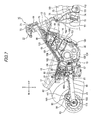
Fig. 1] Fig. 1 is a left-side view for explaining an embodiment of a motorcycle according to the present invention. - [
Fig. 2] Fig. 2 is a left-side view of the motorcycle shown inFig. 1 in which a vehicle body cover and a vehicle body frame are detached therefrom. - [
Fig. 3] Fig. 3 is a plan view of the motorcycle shown inFig. 2 . - [
Fig. 4] Fig. 4 is a perspective view of a peripheral part of a main harness shown inFig. 2 . - [
Fig. 5] Fig. 5 is a left-side view of the peripheral part of the main harness shown inFig. 2 . - [
Fig. 6] Fig. 6 is a right-side view of the peripheral part of the main harness shown inFig. 2 . - [
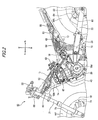
Fig. 7] Fig. 7 is a right-side view of the motorcycle shown inFig. 1 in which the vehicle body cover and the vehicle body frame are detached therefrom. - [
Fig. 8] Fig. 8 is a perspective view of the motorcycle shown inFig. 7 . - [
Fig. 9] Fig. 9 is a perspective view of a peripheral part of ABS pipes shown inFig. 7 - [
Fig. 10] Fig. 10 is a perspective view of a peripheral part of an ABS module shown inFig. 9 . - [
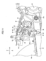
Fig. 11] Fig. 11 is a right-side view of the peripheral part of the ABS module shown inFig. 9 . - [
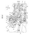
Fig. 12] Fig. 12 is a left-side view of the peripheral part of the ABS module shown inFig. 9 . - [
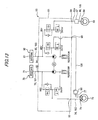
Fig. 13] Fig. 13 is a schematic diagram of a hydraulic circuit. - Hereinafter, an embodiment of a motorcycle according to the present invention will be described in detail with reference to the drawings. Note that the drawings are supposed to be viewed in directions of reference numerals. In the following description, front-to-back, right-to-left, and up-and-down directions are supposed to be in accordance with directions viewed from a driver, and the drawings indicate a front side of a vehicle as Fr, a rear side as Rr, a left side as L, a right side as R, an upper side as U, and a lower side as D. Moreover, in this embodiment, a main harness will be described by using
Fig. 2 to Fig. 6 while a braking apparatus and an ABS of the same vehicle will be described by usingFig. 7 to Fig. 13 in order to facilitate understanding of the drawings. - As shown in
Fig. 1 , amotorcycle 10 of this embodiment includes avehicle body frame 11 which is formed of ahead pipe 12 provided on a front end, a pair of right and leftmain frames 13 extending backward and downward from thehead pipe 12, a pair of right and left downtubes 14 extending backward and downward from thehead pipe 12, a pair of right andleft pivot plates 15 connected to rear end portions of the right and leftmain frames 13, a pair of right andleft seat frames 16 being connected to rear portions of the right and leftmain frames 13 and extending backward and upward, a pair of right andleft sub-frames 17 being connected to thepivot plates 15, extending backward and upward, and having rear end portions connected to rear end portions of theseat frames 16, first tofourth reinforcing frames main frames 13 and thedown tubes 14, and fifth and sixth reinforcingframes 18e and 18f connected between thesear frames 16 and thesub-frames 17. A single-cylinder four-stroke engine 20 is attached to thedown tubes 14 and thepivot plates 15. - Moreover, the
motorcycle 10 includes a pair of right andleft front forks 21 steerably supported on thehead pipe 12, a front wheel WF rotatably supported by lower end portions of thefront forks 21, asteering handle 22 attached to upper end portions of thefront forks 21, a pair of right andleft swing arms 23 swingably supported by thepivot plates 15 viaswing arm pivots 23a , a rear wheel WR rotatably supported by rear end portions of theswing arms 23,rear cushions 24 provided between theswing arms 23 and thepivot plates 15, afuel tank 25 provided above themain frames 13, and adriver seat 26 as well as apillion seat 27 provided above theseat frames 16. - Here, in
Fig. 1 ,reference numeral 31 denotes a front cowl,reference numeral 32 denotes a front side cowl,reference numeral 33 denotes an under cowl, reference numeral 34 denotes a side cowl,reference numeral 36 denotes a head light,reference numeral 37 denotes a side mirror,reference numeral 38 denotes a front blinker,reference numeral 39 denotes a front fender,reference numeral 40 denotes a tail light,reference numeral 41 denotes a rear blinker,reference numeral 42 denotes a rear fender,reference numeral 43 denotes an exhaust pipe,reference numeral 44 denotes a muffler,reference numeral 45 denotes a main step holder,reference numeral 46 denotes a main step,reference numeral 47 denotes a pillion step holder,reference numeral 48 denotes a pillion step, andreference numeral 49 denotes a radiator. - Meanwhile, in
Fig. 2 andFig. 7 ,reference numeral 120 denotes a crankcase of theengine 20,reference numeral 121 denotes a cylinder block joined to an upper part of thecrankcase 120,reference numeral 122 denotes a cylinder head joined to an upper part of thecylinder block 121, andreference numeral 123 denotes a head cover joined to an upper part of thecylinder head 122. Atransmission switching clutch 124 for switching connection and disconnection of power between a crank shaft and a main shaft not shown therein, and awater pump 125 connected to theradiator 49 via awater pipe 126 are attached to a right side portion of thecrankcase 120. Aclutch cable 127 connected to thetransmission switching clutch 124 is connected to a clutch lever 140 (seeFig. 9 ). Meanwhile, as shown inFig. 5 , astarter motor 128 is arranged on an upper face and on the right side of thecrankcase 120, which is connected to a startermagnetic switch 65 to be described later via astarter motor harness 129. In addition, as shown inFig. 6 , athrottle body 130 provided with athrottle drum 131 is connected to a rear side wall of thecylinder head 122. Athrottle cable 132 connected to a base end side (seeFig. 9 ) of thehandle 22 on the right side is wound around and coupled to thethrottle drum 131. - Moreover, in this embodiment, as shown in
Fig. 2 to Fig. 6 , themotorcycle 10 includes amain harness 50 configured to supply power from abattery 61, which is arranged so as to be offset to the left with respect to a vehicle body center line CL, to multiple electrical components between the right andleft seat frames 16. Thismain harness 50 is placed along an inner side of themain frame 13, thedown tube 14, theseat frame 16, thesub-frame 17, and the second reinforcingframe 18b which are arranged on the left side of thevehicle 10. - Here, the multiple electrical components include an
ignition coil 62, anAI solenoid 63, aregulator 64, the startermagnetic switch 65, afuse box 66, a heaterless O2 sensor 67, acombination switch 68, anECU 69, and the like. Moreover, theignition coil 62, theAI solenoid 63, theregulator 64, the startermagnetic switch 65, thefuse box 66, and the heaterless O2 sensor 67 are arranged on the left side relative to the vehicle body center line CL in a vehicle width direction and inside themain frames 13 and theseat frames 16. Note that thehead light 36, thefront blinkers 38, thetail light 40, and therear blinkers 42 are electrical components as well. These electrical components are connected to thebattery 61 by use ofsub-harnesses main harness 50. As shown inFig. 4 andFig. 5 ,reference numeral 51 denotes the sub-harness arranged behind theengine 20 so as to be connected to the ECU arranged on the right side relative to the vehicle body center line CL,reference numeral 52 denotes the sub-harness connected to theregulator 64, andreference numeral 53 denotes the sub-harness connected to the above-described electrical components viaconnectors 54. Meanwhile, inFig. 3 , reference numeral 61a denotes a positive terminal of thebattery 61 andreference numeral 61b denotes a negative terminal of thebattery 61. These are connected to themain harness 50 via thefuse box 66 by using unillustrated couplers. - Moreover, as shown in
Fig. 7 to Fig. 12 , themotorcycle 10 includes afront brake unit 70 configured to apply a braking force to the front wheel WF, arear brake unit 80 configured to apply a braking force to the rear wheel WR, and anABS system 90 configured to adjust the braking forces of thefront brake unit 70 and therear brake unit 80 and to adjust brake hydraulic pressures depending on brake lock conditions of the front and rear wheels WF and WR. Here, inFig. 7 , a frontvehicle speed sensor 111 configured to detect revolution of the front wheel WF by use of asensor rotor 110 fixed to the front wheel WF is connected to theECU 69 via a sub-harness 112, and a rearvehicle speed sensor 116 configured to detect revolution of the rear wheel WR by use of asensor rotor 115 fixed to the rear wheel WR is connected to theECU 69 via asub-harness 117. - The
front brake unit 70 includes afront master cylinder 71 attached to a right end portion of thehandle 22 and configured to apply the braking force to the front wheel WF, afront reserve tank 72 integrally formed with thefront master cylinder 71, afront brake disc 73 attached to the right side of the front wheel WF, afront brake caliper 74 attached to a lower end portion of thefront fork 21 on the right side and configured to sandwich thefront brake disc 73, a firstfront brake hose 75 connected to thefront master cylinder 71, and a secondfront brake hose 76 and a thirdfront brake hose 77 connected to thefront brake caliper 74. - The
rear brake unit 80 includes arear master cylinder 81 attached to themain step holder 45 on the right side and configured to apply the braking force to the rear wheel WR, arear reserve tank 82 connected to therear master cylinder 81 via ahose 82a, arear brake disc 83 attached to the right side of the rear wheel WR, arear brake caliper 84 attached to a lower end portion of theswing arm 23 on the right side and configured to sandwich therear brake disc 83, a firstrear brake hose 85 connected to therear master cylinder 81, and a secondrear brake hose 86 connected to therear brake caliper 84. - As shown in
Fig. 7 to Fig. 13 , theABS system 90 includes anABS modulator 91 arranged so as to be offset to the right with respect to the vehicle body center line CL and configured to control hydraulic pressures in theABS system 90, afirst ABS pipe 101 configured to connect a firstpressure receiving port 92 of theABS modulator 91 to the firstfront brake hose 75, asecond ABS pipe 102 configured to connect a firstpressure feeding port 93 of theABS modulator 91 to the secondfront brake hose 76, athird ABS pipe 103 configured to connect a secondpressure receiving port 94 of theABS modulator 91 to the firstrear brake hose 85, afourth ABS pipe 104 configured to connect a secondpressure feeding port 95 of theABS modulator 91 to a proportional control valve 97 (hereinafter simply abbreviated as the "PCV 97"), afifth ABS pipe 105 configured to connect thePCV 97 to the secondrear brake hose 86, and asixth ABS pipe 106 configured to connect a thirdpressure feeing port 96 of theABS modulator 91 to the thirdfront brake hose 77. Note that thePCV 97 is configured to achieve improvement in running stability by adjusting a proportion of the hydraulic pressures to thefront brake caliper 74 and therear brake caliper 84. - Moreover, the first
front brake hose 75, the secondfront brake hose 76, the thirdfront brake hose 77, thehose 82a, the firstrear brake hose 85, and the secondrear brake hose 86 are formed of pressure-resistant hoses made of rubber. In the meantime, thefirst ABS pipe 101, thesecond ABS pipe 102, thethird ABS pipe 103, thefourth ABS pipe 104, thefifth ABS pipe 105, and thesixth ABS pipe 106 are formed of pressure-resistant pipes made of metal. - Moreover, in this embodiment, as shown in
Fig. 7 to Fig. 9 , thefirst ABS pipe 101, thesecond ABS pipe 102, and thesixth ABS pipe 106 extend forward and substantially in parallel from theABS modulator 91 and are placed along an inner side of themain frame 13 arranged on the right side of thevehicle 10. - According to the
ABS system 90 configured as described above, a hydraulic pressure generated in thefront master cylinder 71 is transmitted sequentially to the firstfront brake hose 75, to thefirst ABS pipe 101, to theABS modulator 91, to thesecond ABS pipe 102, to the secondfront brake hose 76, and to thefront brake caliper 74, thereby generating the braking force onto the front wheel WF. - Meanwhile, a hydraulic pressure generated in the
rear master cylinder 81 is transmitted sequentially to the firstrear brake hose 85, to thethird ABS pipe 103, to theABS modulator 91, to thefourth ABS pipe 104, to thePCV 97, to thefifth ABS pipe 105, to the secondrear brake hose 86, and to therear brake caliper 84 and is also supplied sequentially to theABS modulator 91, to thesixth ABS pipe 106, to adelay valve 98, to the thirdfront brake hose 77, and to thefront brake caliper 74, thereby generating the braking force onto the front wheel WF. - As described above, according to the
motorcycle 10 of this embodiment, themain harness 50 is arranged on the left side of the vehicle while theABS pipes main harness 50 and theABS pipes main harness 50 as well as theABS pipes motorcycle 10. - Moreover, according to the motorcycle of this embodiment, the
main harness 50 is arranged along themain frame 13, thedown tube 14, theseat frame 16, thesub-frame 17, and the second reinforcingframe 18b which are arranged on the left side of the vehicle while theABS pipes main frame 13 on the left side of the vehicle. Hence the distinction between themain harness 50 and theABS pipes main harness 50 and theABS pipes motorcycle 10. - Moreover, according to the
motorcycle 10 of this embodiment, thebrake calipers battery 61 is provided on the vehicle while being offset to the left with respect to the vehicle body center line CL.
Meanwhile, theABS modulator 91 of theABS system 90 is provided on the vehicle while being offset to the right with respect to the vehicle body center line CL. Themain harness 50 is provided along themain frame 13, thedown tube 14, theseat frame 16, thesub-frame 17 and the second reinforcingframe 18b on the left side of the vehicle while theABS pipes main frame 13 on the right side of the vehicle. Therefore, themain harness 50 including the multiple electrical wires and having no limitation of flexibility of design is arranged on the left side of the vehicle as in the case of thebattery 61 while theABS pipes brake calipers ABS modulator 91. Thus, lengths of theABS pipes motorcycle 10. - Moreover, according to the motorcycle of this embodiment, all of the engine electrical components including the
ignition coil 62, theAI solenoid 63, theregulator 64, the startermagnetic switch 65, thefuse box 66, and the heaterless O2 sensor 67 are arranged on the left side relative to the vehicle body center line CL. Therefore, all of theignition coil 62, theAI solenoid 63, theregulator 64, the startermagnetic switch 65, thefuse box 66, and the heaterless O2 sensor 67 are arranged on the same side as themain harness 50 which is arranged on the left side of the vehicle. Thus, as compared with the case where at least one of the above-described engine electrical components is arranged on the right side relative to the vehicle body center line CL, the length of themain harness 50 can be minimized to further suppress manufacturing costs of the motorcycle, and to further facilitate a wiring operation of themain harness 50. - The present invention has been hitherto described in detail and with reference to the specific embodiments, but it is apparent to those skilled in the art that the present invention can be changed or modified in various manners without departing from the scope of the present invention as defined by the appended claims.
-
- 10
- MOTORCYCLE
- 11
- VEHICLE BODY FRAME
- 13
- MAIN FRAME
- 14
- DOWN TUBE
- 15
- PIVOT PLATE
- 16
- SEAT FRAME
- 17
- SUB-FRAME
- 18b
- SECOND REINFORCING FRAME
- 50
- MAIN HARNESS
- 61
- BATTERY
- 62
- IGNITION COIL
- 63
- AI SOLENOID
- 64
- REGULATOR
- 65
- STARTER MAGNETIC SWITCH
- 66
- FUSE BOX
- 67
- HEATERLESS O2 SWITCH
- 70
- FRONT BRAKE UNIT
- 71
- FRONT MASTER CYLINDER
- 74
- FRONT BRAKE CALIPER
- 75
- FIRST FRONT BRAKE HOSE
- 76
- SECOND FRONT BRAKE HOSE
- 77
- THIRD FRONT BRAKE HOSE
- 80
- REAR BRAKE UNIT
- 81
- REAR MASTER CYLINDER
- 84
- REAR BRAKE CALIPER
- 85
- FIRST FRONT BRAKE HOSE
- 86
- SECOND FRONT BRAKE HOSE
- 90
- ABS SYSTEM
- 91
- ABS MODULATOR
- 101
- FIRST ABS PIPE
- 102
- SECOND ABS PIPE
- 103
- THIRD ABS PIPE
- 104
- FOURTH ABS PIPE
- 105
- FIFTH ABS PIPE
- 106
- SIXTH ABS PIPE
- CL
- VEHICLE BODY CENTER LINE
Claims (2)
- A motorcycle comprising:a main harness (50) connected to a battery (61) and arranged to extend in a front-to-back direction of a vehicle in order to supply electric power to a plurality of electrical components (62, 63, 64, 65, 66, 67) provided on the vehiclean anti-lock braking system (90) connected to a brake caliper (74) for a front wheel (WF) and a brake caliper (84) for a rear wheel (WR) and configured to adjust a brake hydraulic pressure depending on brake lock conditions of the front wheel (WF) and the rear wheel (WR);an anti-lock braking system pipe (101, 102, 103, 104, 105, 106) configured to transmit the brake hydraulic pressure of the anti-lock braking system (90);a vehicle body frame (11) including a pair of right and left frames (13, 14, 15, 16, 17, 18a to 18f); andan anti-lock braking system modulator (91) of the anti-lock braking system (90),wherein the main harness (50) and the anti-lock braking system pipe (101, 102, 106) are arranged along the pair of right and left frames (13, 14, 15, 16, 17, 18a to 18f),wherein the brake caliper (74) for the front wheel (WF) is provided on the vehicle while being offset to the right with respect to a vehicle body center line (CL),andwherein the battery (61) is provided on the vehicle while being offset to the left with respect to the vehicle body center line (CL),and characterised in that:the main harness (50) is provided on the left frame (13, 14, 16, 17, 18b) of the pair of right and left frames and the anti-lock braking system pipe (101, 102, 106) is provided on the right frame (13) of the pair of right and left frames,the brake caliper (84) for the rear wheel (WR) is provided on the vehicle while being offset to the right with respect to the vehicle body center line (CL), andtheanti-lockbrakingsystemmodulator (91) of theanti-lock braking system (90) is provided on the vehicle while being offset to the right with respect to the vehicle body center line (CL).
- The motorcycle according to claim 1, wherein the plurality of electrical components includes engine electrical components including an ignition coil (62), an AI solenoid (63), a regulator (64), a starter magnetic switch (65), a fuse box (66) and a heaterless oxygen sensor (67), and
wherein all of the engine electrical components are arranged on the left side of the vehicle body center line (CL).
Applications Claiming Priority (2)
| Application Number | Priority Date | Filing Date | Title |
|---|---|---|---|
| JP2009200502A JP5300142B2 (en) | 2009-08-31 | 2009-08-31 | Motorcycle |
| PCT/JP2010/064841 WO2011025043A1 (en) | 2009-08-31 | 2010-08-31 | Motorcycle |
Publications (3)
| Publication Number | Publication Date |
|---|---|
| EP2447143A1 EP2447143A1 (en) | 2012-05-02 |
| EP2447143A4 EP2447143A4 (en) | 2012-10-10 |
| EP2447143B1 true EP2447143B1 (en) | 2013-10-23 |
Family
ID=43628131
Family Applications (1)
| Application Number | Title | Priority Date | Filing Date |
|---|---|---|---|
| EP10812089.0A Active EP2447143B1 (en) | 2009-08-31 | 2010-08-31 | Motorcycle |
Country Status (9)
| Country | Link |
|---|---|
| US (1) | US8973696B2 (en) |
| EP (1) | EP2447143B1 (en) |
| JP (1) | JP5300142B2 (en) |
| KR (1) | KR101296007B1 (en) |
| CN (1) | CN102481966B (en) |
| AR (1) | AR077979A1 (en) |
| BR (1) | BR112012004512B1 (en) |
| CO (1) | CO6612223A2 (en) |
| WO (1) | WO2011025043A1 (en) |
Families Citing this family (44)
| Publication number | Priority date | Publication date | Assignee | Title |
|---|---|---|---|---|
| JP5728352B2 (en) * | 2011-09-28 | 2015-06-03 | 本田技研工業株式会社 | Saddle riding |
| JP5853663B2 (en) * | 2011-12-16 | 2016-02-09 | スズキ株式会社 | Brake piping structure of motorcycle |
| KR101634029B1 (en) * | 2012-03-21 | 2016-06-27 | 혼다 기켄 고교 가부시키가이샤 | Saddled vehicle |
| JP5845543B2 (en) * | 2012-08-29 | 2016-01-20 | 本田技研工業株式会社 | Motorcycle |
| AP2014008950A0 (en) * | 2013-07-01 | 2015-12-31 | Yamaha Motor Co Ltd | Vehicle provided with leaning-capable vehicle-bodyframe and two front wheels |
| JP6122732B2 (en) * | 2013-08-09 | 2017-04-26 | 本田技研工業株式会社 | Saddle riding vehicle |
| JP6165012B2 (en) * | 2013-09-30 | 2017-07-19 | 本田技研工業株式会社 | Interlocking brake parts arrangement structure for saddle-ride type vehicles |
| JP6023729B2 (en) * | 2014-01-20 | 2016-11-09 | 本田技研工業株式会社 | Motorcycle |
| JP6240574B2 (en) * | 2014-03-19 | 2017-11-29 | 本田技研工業株式会社 | Harness layout structure for saddle riding type vehicles |
| JP2015227100A (en) | 2014-05-30 | 2015-12-17 | ヤマハ発動機株式会社 | Saddle-riding type vehicle |
| JP2016078497A (en) * | 2014-10-10 | 2016-05-16 | ヤマハ発動機株式会社 | Saddle riding type vehicle |
| WO2016152541A1 (en) * | 2015-03-24 | 2016-09-29 | 本田技研工業株式会社 | Saddle-riding-type vehicle exhaust device |
| JP6526997B2 (en) * | 2015-03-26 | 2019-06-05 | 本田技研工業株式会社 | Motorcycle |
| JP6398866B2 (en) * | 2015-05-19 | 2018-10-03 | 株式会社デンソー | Oxygen sensor control method |
| USD816553S1 (en) * | 2016-08-10 | 2018-05-01 | Kwang Yang Motor Co., Ltd. | Motorcycle |
| JP6866091B2 (en) * | 2016-09-13 | 2021-04-28 | 川崎重工業株式会社 | Motorcycle |
| WO2018062421A1 (en) * | 2016-09-30 | 2018-04-05 | 本田技研工業株式会社 | Interlocking brake support structure for saddle-type vehicle |
| JP1584274S (en) * | 2016-11-04 | 2017-08-21 | ||
| JP6404308B2 (en) | 2016-12-27 | 2018-10-10 | 本田技研工業株式会社 | Saddle riding vehicle |
| JP2018134907A (en) | 2017-02-20 | 2018-08-30 | ヤマハ発動機株式会社 | Saddle-riding type vehicle |
| US10723334B2 (en) | 2017-03-28 | 2020-07-28 | Polaris Industries Inc. | Anti-lock brake system for all-terrain vehicle |
| JP2019001208A (en) * | 2017-06-12 | 2019-01-10 | スズキ株式会社 | Body structure of motorcycle |
| CN111032502B (en) * | 2017-09-07 | 2021-06-08 | 本田技研工业株式会社 | Front structure of saddle-type vehicle |
| CN111148691B (en) * | 2017-09-28 | 2021-12-21 | 本田技研工业株式会社 | Brake piping structure for saddle-ride type vehicle |
| EP3689725B1 (en) | 2017-09-29 | 2021-09-29 | Honda Motor Co., Ltd. | Saddle-type vehicle |
| JP6856494B2 (en) * | 2017-10-25 | 2021-04-07 | 矢崎総業株式会社 | Wire harness and its manufacturing method |
| JP6630335B2 (en) * | 2017-11-21 | 2020-01-15 | 本田技研工業株式会社 | Saddle-type vehicle |
| US10967881B2 (en) | 2017-11-22 | 2021-04-06 | Polaris Industries Inc. | Anti-lock braking system for utility vehicle |
| JP6800197B2 (en) * | 2017-12-27 | 2020-12-16 | 本田技研工業株式会社 | Saddle-type vehicle |
| JP6642837B2 (en) * | 2017-12-28 | 2020-02-12 | 本田技研工業株式会社 | ABS arrangement structure of saddle type vehicle |
| JP6773704B2 (en) * | 2018-03-15 | 2020-10-21 | 本田技研工業株式会社 | Rear brake hose layout structure for saddle-riding vehicles |
| CN112469608B (en) | 2018-05-02 | 2023-11-10 | 北极星工业有限公司 | Operating modes using the all-terrain vehicle's braking system |
| US11618422B2 (en) | 2018-11-14 | 2023-04-04 | Polaris Industries Inc. | Operating modes using a braking system for an all terrain vehicle |
| EP3835188B1 (en) * | 2018-08-09 | 2022-12-07 | Honda Motor Co., Ltd. | Saddle riding type vehicle |
| USD921535S1 (en) * | 2019-03-27 | 2021-06-08 | Bayerische Motoren Werke Aktiengesellschaft | Motorcycle, toy, and/or replicas thereof |
| JP1648610S (en) * | 2019-03-29 | 2019-12-23 | ||
| JP7124021B2 (en) * | 2020-08-19 | 2022-08-23 | 本田技研工業株式会社 | straddle-type vehicle |
| WO2022201684A1 (en) * | 2021-03-24 | 2022-09-29 | 本田技研工業株式会社 | Saddle-type vehicle |
| JP7770138B2 (en) * | 2021-08-26 | 2025-11-14 | カワサキモータース株式会社 | Saddle-type vehicle |
| JP7340576B2 (en) * | 2021-09-27 | 2023-09-07 | 本田技研工業株式会社 | saddle type vehicle |
| JP7707139B2 (en) * | 2022-11-28 | 2025-07-14 | 本田技研工業株式会社 | Saddle-type vehicle |
| JP7558240B2 (en) * | 2022-12-09 | 2024-09-30 | 本田技研工業株式会社 | Saddle type vehicle |
| WO2025094291A1 (en) * | 2023-10-31 | 2025-05-08 | ヤマハ発動機株式会社 | Leaning vehicle |
| WO2025094293A1 (en) * | 2023-10-31 | 2025-05-08 | ヤマハ発動機株式会社 | Leaning vehicle |
Family Cites Families (22)
| Publication number | Priority date | Publication date | Assignee | Title |
|---|---|---|---|---|
| GB2078868B (en) * | 1980-05-15 | 1985-04-03 | Honda Motor Co Ltd | Hydraulic pump |
| US4690236A (en) * | 1982-09-29 | 1987-09-01 | Honda Giken Kogyo Kabushiki Kaisha | Motorcycle lubrication system |
| US4809999A (en) * | 1986-03-04 | 1989-03-07 | Honda Giken Kogyo Kabushiki Kaisha | Tubular frame member |
| JPH04260847A (en) | 1991-02-15 | 1992-09-16 | Suzuki Motor Corp | Cable body laying structure in motorcycle |
| JP3094734B2 (en) * | 1993-05-14 | 2000-10-03 | スズキ株式会社 | Anti-skid brake device for motorcycles |
| US5419625A (en) | 1993-05-14 | 1995-05-30 | Suzuki Kabushiki Kaisha | Antiskid braking device for motorcycle |
| JP3376746B2 (en) * | 1995-03-07 | 2003-02-10 | スズキ株式会社 | Motor vehicle speed sensor device |
| JPH09249178A (en) * | 1996-03-18 | 1997-09-22 | Suzuki Motor Corp | Front wheel disc brake device for motorcycles |
| US6193005B1 (en) * | 1997-07-25 | 2001-02-27 | Jesse A. Jurrens | Motorcycle air bag suspension system |
| JP4409638B2 (en) * | 1998-05-06 | 2010-02-03 | ヤマハ発動機株式会社 | Anti-lock brake device for scooter |
| JP4446504B2 (en) * | 1998-10-26 | 2010-04-07 | 本田技研工業株式会社 | Motorcycle braking device |
| US6547027B1 (en) * | 2000-05-19 | 2003-04-15 | Bombardier Inc. | All terrain vehicle |
| US6588529B2 (en) * | 2000-07-05 | 2003-07-08 | Yamaha Hatsudoki Kabishuki Kaisha | Body cover and structure for motorcycle |
| JP4306442B2 (en) * | 2003-12-19 | 2009-08-05 | スズキ株式会社 | Motorcycle with anti-lock brake device |
| JP4851717B2 (en) * | 2005-01-11 | 2012-01-11 | 本田技研工業株式会社 | ABS unit arrangement structure for motorcycles |
| US7690461B2 (en) * | 2005-06-01 | 2010-04-06 | Yamaha Hatsudoki Kabushiki Kaisha | All terrain vehicle |
| JP4326506B2 (en) | 2005-07-01 | 2009-09-09 | 川崎重工業株式会社 | Motorcycle |
| JP4717569B2 (en) * | 2005-09-15 | 2011-07-06 | 川崎重工業株式会社 | Motorcycle |
| JP4805174B2 (en) * | 2006-02-27 | 2011-11-02 | 本田技研工業株式会社 | Motorcycle brake equipment |
| JP2008114617A (en) * | 2006-10-31 | 2008-05-22 | Honda Motor Co Ltd | Vehicle electrical component arrangement structure |
| JP3154637U (en) * | 2008-08-08 | 2009-10-22 | ヤマハ発動機株式会社 | Saddle riding type vehicle |
| JP5503168B2 (en) | 2009-03-19 | 2014-05-28 | 株式会社日立製作所 | Semiconductor integrated circuit device |
-
2009
- 2009-08-31 JP JP2009200502A patent/JP5300142B2/en active Active
-
2010
- 2010-08-26 AR ARP100103128A patent/AR077979A1/en active IP Right Grant
- 2010-08-31 BR BR112012004512-1A patent/BR112012004512B1/en active IP Right Grant
- 2010-08-31 EP EP10812089.0A patent/EP2447143B1/en active Active
- 2010-08-31 US US13/393,057 patent/US8973696B2/en active Active
- 2010-08-31 CN CN201080038369.1A patent/CN102481966B/en active Active
- 2010-08-31 KR KR1020127004249A patent/KR101296007B1/en not_active Expired - Fee Related
- 2010-08-31 WO PCT/JP2010/064841 patent/WO2011025043A1/en not_active Ceased
-
2012
- 2012-02-24 CO CO12032971A patent/CO6612223A2/en active IP Right Grant
Also Published As
| Publication number | Publication date |
|---|---|
| WO2011025043A1 (en) | 2011-03-03 |
| US20120186895A1 (en) | 2012-07-26 |
| CN102481966A (en) | 2012-05-30 |
| BR112012004512A2 (en) | 2016-03-29 |
| BR112012004512B1 (en) | 2019-07-02 |
| CN102481966B (en) | 2015-06-24 |
| KR20120034804A (en) | 2012-04-12 |
| EP2447143A4 (en) | 2012-10-10 |
| EP2447143A1 (en) | 2012-05-02 |
| JP2011051417A (en) | 2011-03-17 |
| KR101296007B1 (en) | 2013-08-12 |
| AR077979A1 (en) | 2011-10-05 |
| JP5300142B2 (en) | 2013-09-25 |
| CO6612223A2 (en) | 2013-02-01 |
| US8973696B2 (en) | 2015-03-10 |
Similar Documents
| Publication | Publication Date | Title |
|---|---|---|
| US8973696B2 (en) | Motorcycle | |
| EP2159143B1 (en) | Motorcycle | |
| EP3486155B1 (en) | Saddle riding vehicle | |
| WO2012067144A1 (en) | Electric saddled vehicle, and drive device for electric vehicle | |
| JP5728352B2 (en) | Saddle riding | |
| JP5816715B2 (en) | Saddle riding | |
| CN104554586B (en) | Straddle-type vehicle | |
| JP5715536B2 (en) | Saddle riding | |
| JP2009234424A (en) | Harness retaining structure for saddle riding type vehicle | |
| EP3486156B1 (en) | Saddle riding vehicle | |
| JP5764025B2 (en) | Saddle riding | |
| US20190322329A1 (en) | Saddle Type Vehicle | |
| EP4023540A1 (en) | Hydraulic control unit, braking system, and saddled vehicle | |
| JP2013071597A (en) | Saddle-ride type vehicle | |
| EP2048051B1 (en) | Straddle-type vehicle | |
| EP3536594B1 (en) | Straddled vehicle mounting of hydraulic and engine control units | |
| JP6531995B2 (en) | Saddle-ride type vehicle | |
| CN219044379U (en) | Saddle-type vehicle | |
| EP3544883B1 (en) | A two-wheeled vehicle with synchronized braking system | |
| JP3157690U (en) | Saddle riding vehicle | |
| JP2015085844A (en) | Saddle riding vehicle | |
| JP2019098864A (en) | Brake piping structure for saddled vehicle | |
| EP2436556B1 (en) | Wiring structure of combination rear light | |
| JP7573583B2 (en) | ABS modulator piping arrangement structure | |
| EP4378768B1 (en) | Brake hydraulic pressure control apparatus and straddle-type vehicle |
Legal Events
| Date | Code | Title | Description |
|---|---|---|---|
| PUAI | Public reference made under article 153(3) epc to a published international application that has entered the european phase |
Free format text: ORIGINAL CODE: 0009012 |
|
| 17P | Request for examination filed |
Effective date: 20120125 |
|
| AK | Designated contracting states |
Kind code of ref document: A1 Designated state(s): AL AT BE BG CH CY CZ DE DK EE ES FI FR GB GR HR HU IE IS IT LI LT LU LV MC MK MT NL NO PL PT RO SE SI SK SM TR |
|
| A4 | Supplementary search report drawn up and despatched |
Effective date: 20120906 |
|
| RIC1 | Information provided on ipc code assigned before grant |
Ipc: B62K 19/38 20060101AFI20120831BHEP Ipc: B62M 7/02 20060101ALI20120831BHEP Ipc: B62J 6/18 20060101ALI20120831BHEP Ipc: B62L 3/02 20060101ALI20120831BHEP Ipc: B60T 8/34 20060101ALI20120831BHEP Ipc: B60T 17/04 20060101ALI20120831BHEP |
|
| DAX | Request for extension of the european patent (deleted) | ||
| REG | Reference to a national code |
Ref country code: DE Ref legal event code: R079 Ref document number: 602010011264 Country of ref document: DE Free format text: PREVIOUS MAIN CLASS: B62K0019380000 Ipc: B62J0006180000 |
|
| GRAP | Despatch of communication of intention to grant a patent |
Free format text: ORIGINAL CODE: EPIDOSNIGR1 |
|
| RIC1 | Information provided on ipc code assigned before grant |
Ipc: B60T 8/36 20060101ALI20130514BHEP Ipc: B62J 6/18 20060101AFI20130514BHEP Ipc: B60T 8/32 20060101ALI20130514BHEP Ipc: B62K 11/04 20060101ALI20130514BHEP Ipc: B62K 19/38 20060101ALI20130514BHEP |
|
| INTG | Intention to grant announced |
Effective date: 20130620 |
|
| GRAS | Grant fee paid |
Free format text: ORIGINAL CODE: EPIDOSNIGR3 |
|
| GRAA | (expected) grant |
Free format text: ORIGINAL CODE: 0009210 |
|
| AK | Designated contracting states |
Kind code of ref document: B1 Designated state(s): AL AT BE BG CH CY CZ DE DK EE ES FI FR GB GR HR HU IE IS IT LI LT LU LV MC MK MT NL NO PL PT RO SE SI SK SM TR |
|
| REG | Reference to a national code |
Ref country code: GB Ref legal event code: FG4D |
|
| REG | Reference to a national code |
Ref country code: CH Ref legal event code: EP |
|
| REG | Reference to a national code |
Ref country code: AT Ref legal event code: REF Ref document number: 637407 Country of ref document: AT Kind code of ref document: T Effective date: 20131115 |
|
| REG | Reference to a national code |
Ref country code: IE Ref legal event code: FG4D |
|
| REG | Reference to a national code |
Ref country code: DE Ref legal event code: R096 Ref document number: 602010011264 Country of ref document: DE Effective date: 20131219 |
|
| REG | Reference to a national code |
Ref country code: NL Ref legal event code: VDEP Effective date: 20131023 |
|
| REG | Reference to a national code |
Ref country code: AT Ref legal event code: MK05 Ref document number: 637407 Country of ref document: AT Kind code of ref document: T Effective date: 20131023 |
|
| REG | Reference to a national code |
Ref country code: LT Ref legal event code: MG4D |
|
| PG25 | Lapsed in a contracting state [announced via postgrant information from national office to epo] |
Ref country code: SE Free format text: LAPSE BECAUSE OF FAILURE TO SUBMIT A TRANSLATION OF THE DESCRIPTION OR TO PAY THE FEE WITHIN THE PRESCRIBED TIME-LIMIT Effective date: 20131023 Ref country code: IS Free format text: LAPSE BECAUSE OF FAILURE TO SUBMIT A TRANSLATION OF THE DESCRIPTION OR TO PAY THE FEE WITHIN THE PRESCRIBED TIME-LIMIT Effective date: 20140223 Ref country code: NL Free format text: LAPSE BECAUSE OF FAILURE TO SUBMIT A TRANSLATION OF THE DESCRIPTION OR TO PAY THE FEE WITHIN THE PRESCRIBED TIME-LIMIT Effective date: 20131023 Ref country code: NO Free format text: LAPSE BECAUSE OF FAILURE TO SUBMIT A TRANSLATION OF THE DESCRIPTION OR TO PAY THE FEE WITHIN THE PRESCRIBED TIME-LIMIT Effective date: 20140123 Ref country code: BE Free format text: LAPSE BECAUSE OF FAILURE TO SUBMIT A TRANSLATION OF THE DESCRIPTION OR TO PAY THE FEE WITHIN THE PRESCRIBED TIME-LIMIT Effective date: 20131023 Ref country code: HR Free format text: LAPSE BECAUSE OF FAILURE TO SUBMIT A TRANSLATION OF THE DESCRIPTION OR TO PAY THE FEE WITHIN THE PRESCRIBED TIME-LIMIT Effective date: 20131023 Ref country code: LT Free format text: LAPSE BECAUSE OF FAILURE TO SUBMIT A TRANSLATION OF THE DESCRIPTION OR TO PAY THE FEE WITHIN THE PRESCRIBED TIME-LIMIT Effective date: 20131023 Ref country code: FI Free format text: LAPSE BECAUSE OF FAILURE TO SUBMIT A TRANSLATION OF THE DESCRIPTION OR TO PAY THE FEE WITHIN THE PRESCRIBED TIME-LIMIT Effective date: 20131023 |
|
| PG25 | Lapsed in a contracting state [announced via postgrant information from national office to epo] |
Ref country code: LV Free format text: LAPSE BECAUSE OF FAILURE TO SUBMIT A TRANSLATION OF THE DESCRIPTION OR TO PAY THE FEE WITHIN THE PRESCRIBED TIME-LIMIT Effective date: 20131023 Ref country code: CY Free format text: LAPSE BECAUSE OF FAILURE TO SUBMIT A TRANSLATION OF THE DESCRIPTION OR TO PAY THE FEE WITHIN THE PRESCRIBED TIME-LIMIT Effective date: 20131023 Ref country code: ES Free format text: LAPSE BECAUSE OF FAILURE TO SUBMIT A TRANSLATION OF THE DESCRIPTION OR TO PAY THE FEE WITHIN THE PRESCRIBED TIME-LIMIT Effective date: 20131023 Ref country code: AT Free format text: LAPSE BECAUSE OF FAILURE TO SUBMIT A TRANSLATION OF THE DESCRIPTION OR TO PAY THE FEE WITHIN THE PRESCRIBED TIME-LIMIT Effective date: 20131023 |
|
| PG25 | Lapsed in a contracting state [announced via postgrant information from national office to epo] |
Ref country code: PT Free format text: LAPSE BECAUSE OF FAILURE TO SUBMIT A TRANSLATION OF THE DESCRIPTION OR TO PAY THE FEE WITHIN THE PRESCRIBED TIME-LIMIT Effective date: 20140224 |
|
| REG | Reference to a national code |
Ref country code: DE Ref legal event code: R097 Ref document number: 602010011264 Country of ref document: DE |
|
| PG25 | Lapsed in a contracting state [announced via postgrant information from national office to epo] |
Ref country code: EE Free format text: LAPSE BECAUSE OF FAILURE TO SUBMIT A TRANSLATION OF THE DESCRIPTION OR TO PAY THE FEE WITHIN THE PRESCRIBED TIME-LIMIT Effective date: 20131023 |
|
| PG25 | Lapsed in a contracting state [announced via postgrant information from national office to epo] |
Ref country code: CZ Free format text: LAPSE BECAUSE OF FAILURE TO SUBMIT A TRANSLATION OF THE DESCRIPTION OR TO PAY THE FEE WITHIN THE PRESCRIBED TIME-LIMIT Effective date: 20131023 Ref country code: SK Free format text: LAPSE BECAUSE OF FAILURE TO SUBMIT A TRANSLATION OF THE DESCRIPTION OR TO PAY THE FEE WITHIN THE PRESCRIBED TIME-LIMIT Effective date: 20131023 Ref country code: RO Free format text: LAPSE BECAUSE OF FAILURE TO SUBMIT A TRANSLATION OF THE DESCRIPTION OR TO PAY THE FEE WITHIN THE PRESCRIBED TIME-LIMIT Effective date: 20131023 Ref country code: PL Free format text: LAPSE BECAUSE OF FAILURE TO SUBMIT A TRANSLATION OF THE DESCRIPTION OR TO PAY THE FEE WITHIN THE PRESCRIBED TIME-LIMIT Effective date: 20131023 |
|
| PLBE | No opposition filed within time limit |
Free format text: ORIGINAL CODE: 0009261 |
|
| STAA | Information on the status of an ep patent application or granted ep patent |
Free format text: STATUS: NO OPPOSITION FILED WITHIN TIME LIMIT |
|
| PG25 | Lapsed in a contracting state [announced via postgrant information from national office to epo] |
Ref country code: DK Free format text: LAPSE BECAUSE OF FAILURE TO SUBMIT A TRANSLATION OF THE DESCRIPTION OR TO PAY THE FEE WITHIN THE PRESCRIBED TIME-LIMIT Effective date: 20131023 |
|
| 26N | No opposition filed |
Effective date: 20140724 |
|
| REG | Reference to a national code |
Ref country code: DE Ref legal event code: R097 Ref document number: 602010011264 Country of ref document: DE Effective date: 20140724 |
|
| PG25 | Lapsed in a contracting state [announced via postgrant information from national office to epo] |
Ref country code: SI Free format text: LAPSE BECAUSE OF FAILURE TO SUBMIT A TRANSLATION OF THE DESCRIPTION OR TO PAY THE FEE WITHIN THE PRESCRIBED TIME-LIMIT Effective date: 20131023 |
|
| PG25 | Lapsed in a contracting state [announced via postgrant information from national office to epo] |
Ref country code: LU Free format text: LAPSE BECAUSE OF FAILURE TO SUBMIT A TRANSLATION OF THE DESCRIPTION OR TO PAY THE FEE WITHIN THE PRESCRIBED TIME-LIMIT Effective date: 20140831 Ref country code: MC Free format text: LAPSE BECAUSE OF FAILURE TO SUBMIT A TRANSLATION OF THE DESCRIPTION OR TO PAY THE FEE WITHIN THE PRESCRIBED TIME-LIMIT Effective date: 20131023 |
|
| REG | Reference to a national code |
Ref country code: CH Ref legal event code: PL |
|
| PG25 | Lapsed in a contracting state [announced via postgrant information from national office to epo] |
Ref country code: LI Free format text: LAPSE BECAUSE OF NON-PAYMENT OF DUE FEES Effective date: 20140831 Ref country code: CH Free format text: LAPSE BECAUSE OF NON-PAYMENT OF DUE FEES Effective date: 20140831 |
|
| REG | Reference to a national code |
Ref country code: DE Ref legal event code: R084 Ref document number: 602010011264 Country of ref document: DE |
|
| REG | Reference to a national code |
Ref country code: GB Ref legal event code: 746 Effective date: 20150507 Ref country code: IE Ref legal event code: MM4A |
|
| REG | Reference to a national code |
Ref country code: DE Ref legal event code: R084 Ref document number: 602010011264 Country of ref document: DE Effective date: 20150505 |
|
| PG25 | Lapsed in a contracting state [announced via postgrant information from national office to epo] |
Ref country code: IE Free format text: LAPSE BECAUSE OF NON-PAYMENT OF DUE FEES Effective date: 20140831 |
|
| PG25 | Lapsed in a contracting state [announced via postgrant information from national office to epo] |
Ref country code: SM Free format text: LAPSE BECAUSE OF FAILURE TO SUBMIT A TRANSLATION OF THE DESCRIPTION OR TO PAY THE FEE WITHIN THE PRESCRIBED TIME-LIMIT Effective date: 20131023 |
|
| PG25 | Lapsed in a contracting state [announced via postgrant information from national office to epo] |
Ref country code: BG Free format text: LAPSE BECAUSE OF FAILURE TO SUBMIT A TRANSLATION OF THE DESCRIPTION OR TO PAY THE FEE WITHIN THE PRESCRIBED TIME-LIMIT Effective date: 20131023 Ref country code: MT Free format text: LAPSE BECAUSE OF FAILURE TO SUBMIT A TRANSLATION OF THE DESCRIPTION OR TO PAY THE FEE WITHIN THE PRESCRIBED TIME-LIMIT Effective date: 20131023 Ref country code: GR Free format text: LAPSE BECAUSE OF FAILURE TO SUBMIT A TRANSLATION OF THE DESCRIPTION OR TO PAY THE FEE WITHIN THE PRESCRIBED TIME-LIMIT Effective date: 20140124 |
|
| REG | Reference to a national code |
Ref country code: FR Ref legal event code: PLFP Year of fee payment: 7 |
|
| PG25 | Lapsed in a contracting state [announced via postgrant information from national office to epo] |
Ref country code: TR Free format text: LAPSE BECAUSE OF FAILURE TO SUBMIT A TRANSLATION OF THE DESCRIPTION OR TO PAY THE FEE WITHIN THE PRESCRIBED TIME-LIMIT Effective date: 20131023 Ref country code: HU Free format text: LAPSE BECAUSE OF FAILURE TO SUBMIT A TRANSLATION OF THE DESCRIPTION OR TO PAY THE FEE WITHIN THE PRESCRIBED TIME-LIMIT; INVALID AB INITIO Effective date: 20100831 |
|
| REG | Reference to a national code |
Ref country code: FR Ref legal event code: PLFP Year of fee payment: 8 |
|
| PG25 | Lapsed in a contracting state [announced via postgrant information from national office to epo] |
Ref country code: MK Free format text: LAPSE BECAUSE OF FAILURE TO SUBMIT A TRANSLATION OF THE DESCRIPTION OR TO PAY THE FEE WITHIN THE PRESCRIBED TIME-LIMIT Effective date: 20131023 |
|
| REG | Reference to a national code |
Ref country code: FR Ref legal event code: PLFP Year of fee payment: 9 |
|
| PG25 | Lapsed in a contracting state [announced via postgrant information from national office to epo] |
Ref country code: AL Free format text: LAPSE BECAUSE OF FAILURE TO SUBMIT A TRANSLATION OF THE DESCRIPTION OR TO PAY THE FEE WITHIN THE PRESCRIBED TIME-LIMIT Effective date: 20131023 |
|
| PGFP | Annual fee paid to national office [announced via postgrant information from national office to epo] |
Ref country code: FR Payment date: 20190711 Year of fee payment: 10 |
|
| REG | Reference to a national code |
Ref country code: DE Ref legal event code: R079 Ref document number: 602010011264 Country of ref document: DE Free format text: PREVIOUS MAIN CLASS: B62J0006180000 Ipc: B62J0011190000 |
|
| PGFP | Annual fee paid to national office [announced via postgrant information from national office to epo] |
Ref country code: GB Payment date: 20190830 Year of fee payment: 10 |
|
| REG | Reference to a national code |
Ref country code: DE Ref legal event code: R082 Ref document number: 602010011264 Country of ref document: DE |
|
| GBPC | Gb: european patent ceased through non-payment of renewal fee |
Effective date: 20200831 |
|
| PG25 | Lapsed in a contracting state [announced via postgrant information from national office to epo] |
Ref country code: FR Free format text: LAPSE BECAUSE OF NON-PAYMENT OF DUE FEES Effective date: 20200831 |
|
| PG25 | Lapsed in a contracting state [announced via postgrant information from national office to epo] |
Ref country code: GB Free format text: LAPSE BECAUSE OF NON-PAYMENT OF DUE FEES Effective date: 20200831 |
|
| PGFP | Annual fee paid to national office [announced via postgrant information from national office to epo] |
Ref country code: DE Payment date: 20240723 Year of fee payment: 15 |
|
| PGFP | Annual fee paid to national office [announced via postgrant information from national office to epo] |
Ref country code: IT Payment date: 20240723 Year of fee payment: 15 |
|
| REG | Reference to a national code |
Ref country code: DE Ref legal event code: R119 Ref document number: 602010011264 Country of ref document: DE |