EP2444224A1 - Vorrichtung und Verfahren zur Herstellung von Kugellagerringen - Google Patents
Vorrichtung und Verfahren zur Herstellung von Kugellagerringen Download PDFInfo
- Publication number
- EP2444224A1 EP2444224A1 EP11184732A EP11184732A EP2444224A1 EP 2444224 A1 EP2444224 A1 EP 2444224A1 EP 11184732 A EP11184732 A EP 11184732A EP 11184732 A EP11184732 A EP 11184732A EP 2444224 A1 EP2444224 A1 EP 2444224A1
- Authority
- EP
- European Patent Office
- Prior art keywords
- mold
- ball bearing
- cylinder
- outer ring
- dividing
- Prior art date
- Legal status (The legal status is an assumption and is not a legal conclusion. Google has not performed a legal analysis and makes no representation as to the accuracy of the status listed.)
- Granted
Links
- 238000000034 method Methods 0.000 title claims abstract description 8
- 238000002347 injection Methods 0.000 claims abstract description 22
- 239000007924 injection Substances 0.000 claims abstract description 22
- 238000004519 manufacturing process Methods 0.000 claims abstract description 9
- 239000004033 plastic Substances 0.000 claims abstract description 7
- 238000001746 injection moulding Methods 0.000 claims abstract description 6
- 238000000465 moulding Methods 0.000 claims description 9
- 150000001875 compounds Chemical class 0.000 claims description 8
- 238000007711 solidification Methods 0.000 claims description 5
- 230000008023 solidification Effects 0.000 claims description 5
- 238000001816 cooling Methods 0.000 claims 1
- 238000000926 separation method Methods 0.000 description 9
- 230000015572 biosynthetic process Effects 0.000 description 5
- 239000000463 material Substances 0.000 description 4
- 238000011161 development Methods 0.000 description 3
- 230000018109 developmental process Effects 0.000 description 3
- 239000007787 solid Substances 0.000 description 2
- 238000009825 accumulation Methods 0.000 description 1
- 238000007596 consolidation process Methods 0.000 description 1
- 230000006735 deficit Effects 0.000 description 1
- 238000006073 displacement reaction Methods 0.000 description 1
- 238000005507 spraying Methods 0.000 description 1
- 229920001169 thermoplastic Polymers 0.000 description 1
- 239000012815 thermoplastic material Substances 0.000 description 1
- 229920005992 thermoplastic resin Polymers 0.000 description 1
- 239000004416 thermosoftening plastic Substances 0.000 description 1
Images

Classifications
-
- B—PERFORMING OPERATIONS; TRANSPORTING
- B29—WORKING OF PLASTICS; WORKING OF SUBSTANCES IN A PLASTIC STATE IN GENERAL
- B29C—SHAPING OR JOINING OF PLASTICS; SHAPING OF MATERIAL IN A PLASTIC STATE, NOT OTHERWISE PROVIDED FOR; AFTER-TREATMENT OF THE SHAPED PRODUCTS, e.g. REPAIRING
- B29C45/00—Injection moulding, i.e. forcing the required volume of moulding material through a nozzle into a closed mould; Apparatus therefor
- B29C45/17—Component parts, details or accessories; Auxiliary operations
- B29C45/40—Removing or ejecting moulded articles
- B29C45/44—Removing or ejecting moulded articles for undercut articles
- B29C45/4421—Removing or ejecting moulded articles for undercut articles using expansible or collapsible cores
-
- B—PERFORMING OPERATIONS; TRANSPORTING
- B29—WORKING OF PLASTICS; WORKING OF SUBSTANCES IN A PLASTIC STATE IN GENERAL
- B29C—SHAPING OR JOINING OF PLASTICS; SHAPING OF MATERIAL IN A PLASTIC STATE, NOT OTHERWISE PROVIDED FOR; AFTER-TREATMENT OF THE SHAPED PRODUCTS, e.g. REPAIRING
- B29C45/00—Injection moulding, i.e. forcing the required volume of moulding material through a nozzle into a closed mould; Apparatus therefor
- B29C45/17—Component parts, details or accessories; Auxiliary operations
- B29C45/26—Moulds
- B29C45/2616—Moulds having annular mould cavities
-
- B—PERFORMING OPERATIONS; TRANSPORTING
- B29—WORKING OF PLASTICS; WORKING OF SUBSTANCES IN A PLASTIC STATE IN GENERAL
- B29C—SHAPING OR JOINING OF PLASTICS; SHAPING OF MATERIAL IN A PLASTIC STATE, NOT OTHERWISE PROVIDED FOR; AFTER-TREATMENT OF THE SHAPED PRODUCTS, e.g. REPAIRING
- B29C45/00—Injection moulding, i.e. forcing the required volume of moulding material through a nozzle into a closed mould; Apparatus therefor
- B29C45/17—Component parts, details or accessories; Auxiliary operations
- B29C45/26—Moulds
- B29C45/2681—Moulds with rotatable mould parts
-
- B—PERFORMING OPERATIONS; TRANSPORTING
- B29—WORKING OF PLASTICS; WORKING OF SUBSTANCES IN A PLASTIC STATE IN GENERAL
- B29C—SHAPING OR JOINING OF PLASTICS; SHAPING OF MATERIAL IN A PLASTIC STATE, NOT OTHERWISE PROVIDED FOR; AFTER-TREATMENT OF THE SHAPED PRODUCTS, e.g. REPAIRING
- B29C45/00—Injection moulding, i.e. forcing the required volume of moulding material through a nozzle into a closed mould; Apparatus therefor
- B29C45/17—Component parts, details or accessories; Auxiliary operations
- B29C45/46—Means for plasticising or homogenising the moulding material or forcing it into the mould
- B29C45/56—Means for plasticising or homogenising the moulding material or forcing it into the mould using mould parts movable during or after injection, e.g. injection-compression moulding
- B29C45/5605—Rotatable mould parts
-
- F—MECHANICAL ENGINEERING; LIGHTING; HEATING; WEAPONS; BLASTING
- F16—ENGINEERING ELEMENTS AND UNITS; GENERAL MEASURES FOR PRODUCING AND MAINTAINING EFFECTIVE FUNCTIONING OF MACHINES OR INSTALLATIONS; THERMAL INSULATION IN GENERAL
- F16C—SHAFTS; FLEXIBLE SHAFTS; ELEMENTS OR CRANKSHAFT MECHANISMS; ROTARY BODIES OTHER THAN GEARING ELEMENTS; BEARINGS
- F16C19/00—Bearings with rolling contact, for exclusively rotary movement
- F16C19/02—Bearings with rolling contact, for exclusively rotary movement with bearing balls essentially of the same size in one or more circular rows
- F16C19/04—Bearings with rolling contact, for exclusively rotary movement with bearing balls essentially of the same size in one or more circular rows for radial load mainly
- F16C19/06—Bearings with rolling contact, for exclusively rotary movement with bearing balls essentially of the same size in one or more circular rows for radial load mainly with a single row or balls
-
- F—MECHANICAL ENGINEERING; LIGHTING; HEATING; WEAPONS; BLASTING
- F16—ENGINEERING ELEMENTS AND UNITS; GENERAL MEASURES FOR PRODUCING AND MAINTAINING EFFECTIVE FUNCTIONING OF MACHINES OR INSTALLATIONS; THERMAL INSULATION IN GENERAL
- F16C—SHAFTS; FLEXIBLE SHAFTS; ELEMENTS OR CRANKSHAFT MECHANISMS; ROTARY BODIES OTHER THAN GEARING ELEMENTS; BEARINGS
- F16C33/00—Parts of bearings; Special methods for making bearings or parts thereof
- F16C33/30—Parts of ball or roller bearings
- F16C33/58—Raceways; Race rings
- F16C33/64—Special methods of manufacture
-
- F—MECHANICAL ENGINEERING; LIGHTING; HEATING; WEAPONS; BLASTING
- F16—ENGINEERING ELEMENTS AND UNITS; GENERAL MEASURES FOR PRODUCING AND MAINTAINING EFFECTIVE FUNCTIONING OF MACHINES OR INSTALLATIONS; THERMAL INSULATION IN GENERAL
- F16C—SHAFTS; FLEXIBLE SHAFTS; ELEMENTS OR CRANKSHAFT MECHANISMS; ROTARY BODIES OTHER THAN GEARING ELEMENTS; BEARINGS
- F16C2220/00—Shaping
- F16C2220/02—Shaping by casting
- F16C2220/04—Shaping by casting by injection-moulding
Definitions
- the invention further relates to a method for the production of ball bearing rings with grooves according to the preamble of claim 8.
- the invention further relates to the inner ring or outer ring of a Radial ball bearing according to claims 10 and 11.
- thermoplastic molded parts with undercuts injection molds are known in which so-called folding cores are used.
- the outer surfaces of the segments of these cores form in the injection state, the mold for the inner wall of the molded part. If this inner wall has undercuts, then the folding core must be in a demoulding state on a smaller outer diameter can be brought, which allows the demolding of the molded part of the folding core.
- the folding cores make this possible in that their segments coincide with each other during axial movement along a carrier profile to the inside.
- a folding core of the aforementioned type is for example from the DE 26 19 046 C3 known.
- a disadvantage of the known Faltkemen is that the individual segments of the Faltkerns cause about its circumference at the abutting edges separation marks, which are problematic in the production of ball bearing rings with grooves, since the separation marks can affect the movement of the balls of the ball bearing.
- the invention has for its object to provide an apparatus for producing ball bearing rings with grooves in the plastic injection molding process, are avoided in such protruding separation marks. According to the invention, this object is solved by the features of the characterizing part of patent claim 1.
- an apparatus for the production of ball bearing rings with grooves in the plastic injection molding in which the formation of protruding separation marks is avoided.
- a change in diameter in the form of a raised wedge is arranged on both dividing edges of each form segment.
- a diameter change in the form of a notch is arranged at a dividing edge of each shape segment, wherein the carrier profile is designed to be rotatable about its axis.
- the carrier profile is connected to a stepper motor over which it is rotatable.
- a radially movable cylinder is arranged in the mold in the region of the dividing edges.
- This cylinder causes a reduced material thickness in the region of the dividing edge, so that the wall in this area can be spent in the direction of the cylinder during the formation of the separation mark.
- the cylinder advantageously on its side facing the folding core on a concavity whose inner contour corresponds to the outer contour of the curved portion of a form segment.
- a slide is arranged laterally on the cylinder, which can be adjusted to the cylinder. Through the slide access to the cylinder-receiving space of the injection molded part is possible, whereby a subsequent ejection of the space is made possible with plastic.
- the following invention is further based on the object to provide a method for producing ball bearing rings with grooves in which the formation of protruding separation marks is avoided. According to the invention, this object is solved by the features of the characterizing part of claim 8.
- a method for the production of ball bearing rings with grooves in which the formation of protruding separation marks is avoided.
- Advantageously in the region of the dividing edges are radial Employed cylinder of the mold then retracted and subsequently molding compound is injected into the caused by the cylinder recesses. As a result, the formation of a massive cross-section is effected.
- the subject of the present invention is furthermore an inner ring or an outer ring of a radial ball bearing in which circumferential grooves are arranged transversely to the groove. These notches receive the separation marks and cause an unobstructed run of the balls within the ball bearing.
- the subject of the invention is an inner ring or outer ring of a radial ball bearing, in which the raceway groove has circumferentially transversely to this arranged solidification.
- These solidifications result from the leveling of the release marks following the injection molding process, thereby achieving an unobstructed run of the balls in the ball bearing.
- opposing the consolidations in the inner or outer ring are arranged. These Nachspritzmarken result from the filling of the cylinder cavity, whereby a continuous solid cross-section of the inner and outer ring is achieved.
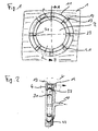
- the device selected as an embodiment according to FIG. 1 essentially comprises an injection mold 1 which has an in-mold FIG. 2 indicated - injection module 10 can be closed and filled with plastic material.
- a folding core 2 is arranged, which is formed from segments 3.
- the inner contour 11 of the injection mold 1 forms, together with the outer contour of the folding core 2, the ball bearing ring 4 to be produced.
- Details of the form 1, in particular the drive means for the displacement of parts of the mold for opening and closing and the carrier profile for the segments 3 of the folding core 2 are not shown in detail.
- the basic design of such an injection mold 1 and the segments 3 of the folding core 2 receiving carrier profile are among those skilled in the art from the DE 101 27 566 C1 well known.
- cylinders 12 are circumferentially arranged in the embodiment in the region of the dividing edges 31 of the segments 3 of the folding core 2, which are designed to be radially displaceable.
- the cylinders 12 have on their side facing the folding core on a concavity 13, which corresponds to the outer contour of the curved portion 32 of the segments 3.
- the cylinder chamber 12 accommodating the cylinder chamber 14 of the injection mold 1 is provided on one side with an opening which can be closed by an axially displaceable slider 15.
- the folding core 2 is formed in the embodiment by eight only schematically illustrated segments 3, which have a curved portion 32 on its radially outward side.
- the outer contour of the curved portions 32 of the segments 3 serve to form the raceway groove of the ball bearing ring 4 to be manufactured.
- Each at its according to the sectional view in FIG FIG. 1 Counterclockwise outer dividing edge is at the curved portion 32 of each segment 3, a notch 33 is introduced, which extends over the entire outer circumference of the curved portion 32. This results in the region of the dividing edges 31 of the segment 3 circumferential furrows 21st
- injection module 10 liquefied thermoplastic resin introduced into the gap formed between the inner contour 11 of the injection mold 1 and the outer contour of the Faltkerns 2.
- the cylinders 12 protrude from the inner contour 11 of the injection mold 1, so that in the ball bearing ring 4 cylinder chambers 41 are formed.
- the liquefied plastic material penetrates on the opposite side of the cylinders 12 in the grooves formed by the notches 33 of the segments 3 furrows 21 of the folding core.
- the folding core 2 is rotated counterclockwise by about 15 ° via a drive (not shown), whereby the molding compound located in the grooves 21 of the folding core 2 is pressed against the cylinders 12 of the injection mold 1 and leveled. This results in the area of the dividing edges 31 solidified zones. Subsequently, the cylinders 12 are retracted into the injection mold 1 and the slide 15 are moved out of the cylinders 12 formed by the cylinder chambers 41 of the ball bearing ring 4. Through the thus released opening the cylinder chambers 41 are now filled with thermoplastic material, so that a continuous solid cross-section of the ball bearing rings 4 is achieved.
- the injection mold 1 is opened and the folding core 2 in a known manner by axial movement of the segments 3 on the - not shown - Carrier profile "folded" so that the now cooled plasticized ball bearing ring can be removed.
- the ball bearing ring 4 produced in this way is characterized in that its raceway groove 42 has peripherally arranged transversalities. Opposite these solidifications are also detected by filling the cylinder chambers 41 Nachspritzmarken.
- the bulges 34 are formed such that in each case the two bulges at the dividing edge 31 of two adjacent segments 3 to form a circumferentially extending the arched portion 32 bridge with triangular cross-section.
- no cylinders or slides are present in the injection mold 1.
- a rotation of the folding core 2 is not required.
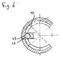
- FIG. 6 schematically the cross section of an inner ring produced in this device and an outer ring is shown. It can be seen that the ball cage formed by inner and outer ring is not affected by the separation marks arranged in the grooves 43. In addition, a rotation of the folding core 2 is not required.
Landscapes
- Engineering & Computer Science (AREA)
- Mechanical Engineering (AREA)
- Manufacturing & Machinery (AREA)
- General Engineering & Computer Science (AREA)
- Moulds For Moulding Plastics Or The Like (AREA)
- Rolling Contact Bearings (AREA)
- Injection Moulding Of Plastics Or The Like (AREA)
Abstract
Description
- Die Erfindung betrifft eine Vorrichtung zur Herstellung von Kugellagerringen mit Laufrillen im Kunststoffspritzverfahren nach dem Oberbegriff des Patentanspruchs 1. Die Erfindung betrifft weiterhin ein Verfahren zur Herstellung von Kugellagerringen mit Laufrillen nach dem Oberbegriff des Patentanspruchs 8. Die Erfindung betrifft darüber hinaus den Innenring bzw. Außenring eines Radialkugellagers nach den Patentansprüchen 10 und 11.
- Zur Herstellung von Thermoplastformteilen mit Hinterschneidungen sind Spritzgießformen bekannt, bei denen so genannte Faltkerne eingesetzt werden. Dabei bilden die Außenflächen der Segmente dieser Faltkerne im Spritzzustand die Form für die Innenwandung des Spritzteils. Weist diese Innenwandung Hinterschneidungen auf, so muss der Faltkern im Entformungszustand auf einen kleineren Außendurchmesser gebracht werden, der das Entformen des Spritzteils von dem Faltkern ermöglicht. Die Faltkerne ermöglichen dies dadurch, dass deren Segmente bei Axialbewegung entlang eines Trägerprofils nach Innen zusammen fallen. Ein Faltkern der vorgenannten Art ist beispielsweise aus der
DE 26 19 046 C3 bekannt. - Nachteilig an den bekannten Faltkemen ist es, dass die einzelnen Segmente des Faltkerns über ihrem Umfang an den Stoßkanten Trennmarkierungen bewirken, welche bei der Herstellung von Kugellagerringen mit Laufrillen problematisch sind, da die Trennmarkierungen die Bewegung der Kugeln des Kugellagers beeinträchtigen können.
- Hier will die Erfindung Abhilft schaffen. Der Erfindung liegt die Aufgabe zugrunde, eine Vorrichtung zur Herstellung von Kugellagerringen mit Laufrillen im Kunststoffspritzgießverfahren bereit zu stellen, bei der derartige hervorstehende Trennmarkierungen vermieden sind. Gemäß der Erfindung wird diese Aufgabe durch die Merkmale des kennzeichnenden Teils des Patentanspruchs 1 gelöst.
- Mit der Erfindung ist eine Vorrichtung zur Herstellung von Kugellagerringen mit Laufrillen im Kunststoffspritzgießverfahren geschaffen, bei der die Bildung von hervorstehenden Trennmarkierungen vermieden ist. Durch das Vorsehen einer Durchmesseränderung an wenigstens einer Teilungskante eines jeden Formsegments des Faltkerns ist eine Beeinflussung der zwischen den Segmenten herausbildenden Trennmarkierung ermöglicht.
- In Weiterbildung der Erfindung ist an beiden Teilungskanten eines jeden Formsegments eine Durchmesseränderung in Form eines erhabenen Keils angeordnet. Hierdurch ist eine Innenwölbung im Bereich der Trennmarkierung erzielt, welche einem Hervorstehen der Trennmarkierung entgegen wirkt.
- In weiterer Ausgestaltung der Erfindung ist an einer Teilungskante eines jeden Formsegments eine Durchmesseränderung in Form einer Kerbe angeordnet, wobei das Trägerprofil um seine Achse rotierbar ausgeführt ist. Durch die Kerbe ist eine gezielte Materialanhäufung bewirkt, welche durch eine sich unmittelbar an dem Spritzgießvorgang anschließende Rotation des Trägerprofils um seine Achse gleichmäßig glatt geformt werden kann. Vorteilhaft ist das Trägerprofil mit einem Schrittmotor verbunden, über den es rotierbar ist.
- In weiterer Ausgestaltung der Erfindung ist in der Form im Bereich der Teilungskanten jeweils ein radial verfahrbarer Zylinder angeordnet. Dieser Zylinder bewirkt eine verringerte Materialdicke im Bereich der Teilungskante, sodass die Wandung in diesem Bereich im Zuge der Glattformung der Trennmarkierung in Richtung des Zylinders verbracht werden kann. Dabei weist der Zylinder vorteilhaft an seiner dem Faltkern zugewandten Seite eine Einwölbung auf, deren Innenkontur mit der Außenkontur des gewölbten Abschnitts eines Formsegments korrespondiert.
- In Weiterbildung der Erfindung ist an dem Zylinder seitlich ein Schieber angeordnet, der an den Zylinder anstellbar ist. Durch den Schieber ist ein Zugang zu dem zylinderaufnehmenden Raum des Spritzgießteils ermöglicht, wodurch ein anschließendes Ausspritzen des Raums mit Kunststoff ermöglicht ist.
- Der folgenden Erfindung liegt weiterhin die Aufgabe zugrunde, ein Verfahren zur Herstellung von Kugellagerringen mit Laufrillen zu schaffen, bei dem die Ausbildung von hervorstehenden Trennmarkierungen vermieden ist. Gemäß der Erfindung wird diese Aufgabe durch die Merkmale des kennzeichnenden Teils des Patentanspruchs 8 gelöst.
- Mit der Erfindung ist ein Verfahren zur Herstellung von Kugellagerringen mit Laufrillen geschaffen, bei dem die Ausbildung von hervorstehenden Trennmarkierungen vermieden ist. Vorteilhaft werden im Bereich der Teilungskanten radial angestellte Zylinder der Form anschließend zurückgefahren und nachfolgend wird Formmasse in die durch die Zylinder bewirkten Ausnehmungen eingespritzt. Hierdurch ist die Ausbildung eines massiven Querschnitts bewirkt.
- Gegenstand der vorliegenden Erfindung ist weiterhin ein Innenring bzw. ein Außenring eines Radialkugellagers bei dem umlaufend zur Laufrille quer zu dieser verlaufende Kerben angeordnet sind. Diese Kerben nehmen die Trennmarkierungen auf und bewirken einen ungehinderten Lauf der Kugeln innerhalb des Kugellagers.
- Weiterhin ist Gegenstand der Erfindung ein Innenring oder Außenring eines Radialkugellagers, bei dem die Laufrille umlaufend quer zu dieser angeordnete Verfestigung aufweist. Diese Verfestigungen resultieren aus der Einebnung der Trennmarkierungen im Anschluss an das Spritzgießverfahren, wodurch ein ungehinderter Lauf der Kugeln in dem Kugellager erzielt ist. Dabei sind Verfahrensbedingt gegenüberliegend den Verfestigungen in dem Innen- bzw. Außenring Nachspritzmarken angeordnet. Diese Nachspritzmarken resultieren durch die Auffüllung des Zylinderhohlraums, wodurch ein durchgehend massiver Querschnitt des Innen- bzw. Außenrings erzielt ist.
- Andere Weiterbildungen und Ausgestaltungen der Erfindung sind in den übrigen Unteransprüchen angegeben. Ein Ausführungsbeispiel der Erfindung ist in den Zeichnung dargestellt und wird nachfolgend im Einzelnen beschrieben. Es zeigen:
- Fig. 1
- die schematische Darstellung einer Vorrichtung zur Herstellung von Kugellagerringen mit Laufrillen im Kunststoffspritzgießverfahren mit innenliegendem Faltkern unmittelbar nach Abschluss der Einspritzphase im Schnitt (Spritzgießform angedeutet);
- Fig. 2
- die schematische Darstellung der Vorrichtung aus
Figur 1 im Schnitt A-B; - Fig. 3
- die schematische Darstellung des Details "Y" in
Figur 2 mit ausgefahrenem Schieber (Nachspritzvorgang); - Fig. 4
- die schematische Darstellung der Detailansicht aus
Figur 3 im Schnitt "Z-Z"; - Fig. 5
- die schematische Darstellung der Detailansicht aus
Figur 3 aus der Ansicht A und - Fig. 6
- die schematische Darstellung einer Vorrichtung zur Herstellung von Kugellagerringen mit Laufrillen in einer zweiten Ausführungsform in Schnittdarstellung (Vorrichtung für Innenring angedeutet).
- Die als Ausführungsbeispiel gewählte Vorrichtung gemäß
Figur 1 umfasst im Wesentlichen eine Spritzgießform 1, welche über ein in -Figur 2 angedeutetes - Einspritzmodul 10 verschließbar und mit Kunststoffmasse verfüllbar ist. Innerhalb der Spritzgießform 1 ist ein Faltkern 2 angeordnet, der aus Segmenten 3 gebildet ist. Die Innenkontur 11 der Spritzgießform 1 bildet zusammen mit der Außenkontur des Faltkerns 2 den zu fertigenden Kugellagerring 4 aus. Einzelheiten der Form 1, insbesondere der Antriebsmittel für die Verschiebung von Teilen der Form zum Öffnen und Schließen sowie das Trägerprofil für die Segmente 3 des Faltkerns 2 sind im Einzelnen nicht dargestellt. Die grundsätzliche Gestaltung einer solchen Spritzgießform 1 sowie des die Segmente 3 des Faltkerns 2 aufnehmenden Trägerprofils sind dem Fachmann u. a. aus derDE 101 27 566 C1 hinlänglich bekannt. - Innerhalb der Spritzgießform 1 sind im Ausführungsbeispiel im Bereich der Teilungskanten 31 der Segmente 3 des Faltkerns 2 umlaufend acht Zylinder 12 angeordnet, welche radial verschiebbar ausgebildet sind. Die Zylinder 12 weisen an ihrer dem Faltkern zugewandten Seite eine Einwölbung 13 auf, die mit der Außenkontur des gewölbten Abschnitts 32 der Segmente 3 korrespondiert. Der die Zylinder 12 aufnehmende Zylinderraum 14 der Spritzgießform 1 ist an einer Seite mit einer Öffnung versehen, welche über einen axial verschiebbaren Schieber 15 verschließbar ist.
- Der Faltkern 2 ist im Ausführungsbeispiel gebildet durch acht lediglich schematisch dargestellte Segmente 3, welche an ihrer radial nach außen gerichteten Seite einen gewölbten Abschnitt 32 aufweisen. Die Außenkontur der gewölbten Abschnitte 32 der Segmente 3 dienen der Ausbildung der Laufrille des zu fertigenden Kugellagerrings 4. Jeweils an ihrer gemäß der Schnittdarstellung in
Figur 1 im Gegenuhrzeigersinn äußeren Teilungskante ist an dem gewölbten Abschnitt 32 eines jeden Segments 3 eine Kerbe 33 eingebracht, welche sich über den gesamten Außenumfang des gewölbten Abschnitts 32 erstreckt. Hierdurch ergeben sich im Bereich der Teilungskanten 31 des Segments 3 umlaufende Furchen 21. - Bei der Herstellung eines Kugellagerrings wird zunächst über das in
Figur 2 angedeutete Einspritzmodul 10 verflüssigter Thermoplastkunststoff in den zwischen der Innenkontur 11 der Spritzgießform 1 und der Außenkontur des Faltkerns 2 gebildeten Zwischenraum eingebracht. Dabei ragen die Zylinder 12 aus der Innenkontur 11 der Spritzgießform 1 hervor, sodass in dem Kugellagerring 4 Zylinderräume 41 gebildet sind. Das verflüssigte Kunststoffmaterial dringt dabei auf der den Zylindern 12 gegenüberliegenden Seite in die durch die Kerben 33 der Segmente 3 gebildeten Furchen 21 des Faltkerns ein. Nach dem Einspritzen der Formmasse wird der Faltkern 2 über einen - nicht dargestellten - Antrieb entgegen dem Uhrzeigersinn um etwa 15° rotiert, wodurch die in den Furchen 21 des Faltkerns 2 befindliche Formmasse gegen die Zylinder 12 der Spritzgießform 1 gepresst und eingeebnet wird. Hierdurch entstehen im Bereich der Teilungskanten 31 verfestigte Zonen. Nachfolgend werden die Zylinder 12 in die Spritzgießform 1 eingefahren und die Schieber 15 werden aus den durch die Zylinder 12 ausgebildeten Zylinderräume 41 des Kugellagerrings 4 herausgefahren. Durch die so freigegebene Öffnung werden die Zylinderräume 41 nun mit thermoplastischem Kunststoffmaterial verfüllt, sodass ein durchgehend massiver Querschnitt der Kugellagerringe 4 erzielt ist. Nachfolgend wird die Spritzgießform 1 geöffnet und der Faltkern 2 in bekannter Art und Weise durch axiale Bewegung der Segmente 3 auf dem - nicht dargestellten - Trägerprofil "zusammengefaltet", sodass der nunmehr abgekühlte plastifizierte Kugellagerring entnommen werden kann. Der so hergestellte Kugellagerring 4 zeichnet sich dadurch aus, dass dessen Laufrille 42 umlaufend quer zu dieser angeordnete Verfestigungen aufweist. Gegenüberliegend dieser Verfestigungen sind zudem durch das Verfüllen der Zylinderräume 41 Nachspritzmarken feststellbar. - Im Ausführungsbeispiel gemäß
Figur 6 sind an beiden Teilungskanten 31 der Segmente 3 an den gewölbten Abschnitten 32 nach außen sich konisch erweiternde Aufwölbungen 34 angeformt. Dabei sind die Aufwölbungen 34 derart ausgebildet, dass sich jeweils die beiden Aufwölbungen an der Teilungskante 31 zweier benachbarter Segmente 3 zu einem umlaufend des gewölbten Abschnitts 32 verlaufenden Steg mit dreieckförmigen Querschnitt ergänzen. In dieser Ausführungsform sind in der Spritzgießform 1 keine Zylinder oder Schieber vorhanden. Zudem ist eine Rotation des Faltkerns 2 nicht erforderlich. Beim Einbringen der Formmasse in den zwischen der Innenkontur 11 der Spritzgießform 1 und der Außenkontur des Faltkerns 2 gebildeten Formraum wird durch die Aufwölbungen 34 Formmasse verdrängt, wodurch im Bereich der Teilungskanten 31 quer zur Laufrille 42 Furchen 43 ausgebildet sind. Die sich im Bereich der Teilungskanten 31 ausbildenden Trennmarkierungen sind innerhalb dieser Furchen 43 angeordnet, sodass sie nicht in die Laufrille 42 hineinragen, wodurch eine Beeinträchtigung des Laufs der Kugeln des Kugellagers vermieden ist. InFigur 6 ist schematisch der Querschnitt eines in dieser Vorrichtung hergestellten Innenrings und eines Außenrings dargestellt. Es ist ersichtlich, dass der durch Innen- und Außenring gebildete Kugelkäfig durch die in den Furchen 43 angeordneten Trennmarken nicht beeinträchtigt ist. Zudem ist eine Rotation des Faltkerns 2 nicht erforderlich.
Claims (12)
- Vorrichtung zur Herstellung von Kugellagerringen mit Laufrillen im Kunststoffspritzgießverfahren, umfassend eine Form mit einem Faltkern, der aus Formsegmenten gebildet ist, die axial verschiebbar auf einem Trägerprofil angeordnet sind und gewölbte Abschnitte zur Ausformung der Laufrille aufweisen, dadurch gekennzeichnet, dass der gewölbte Abschnitt (32) eine jeden Formsegments (3) an wenigstens einer Teilungskante (31) des Formsegments (3) eine Durchmesseränderung aufweist.
- Vorrichtung nach Anspruch 1, dadurch gekennzeichnet, dass an beiden Teilungskanten (31) eines jeden Formsegments (3) eine Durchmesseränderung in Form eines erhabenen Keils angeordnet ist.
- Vorrichtung nach Anspruch 1, dadurch gekennzeichnet, dass an einer Teilungskante (31) eine Durchmesseränderung in Form einer Kerbe (33) angeordnet ist, wobei das Trägerprofil um seine Achse rotierbar ausgeführt ist.
- Vorrichtung nach Anspruch 3, dadurch gekennzeichnet, dass das Trägerprofil mit einem Schrittmotor verbunden ist, über den es rotierbar ist.
- Vorrichtung nach einem der Ansprüche 3 bis 4, dadurch gekennzeichnet, dass in der Form (1) im Bereich der Teilungskanten (31) jeweils ein radial verfahrbarer Zylinder (12) angeordnet ist.
- Vorrichtung nach Anspruch 5, dadurch gekennzeichnet, dass der Zylinder (12) an seiner dem Faltkern (2) zugewandten Seite eine Einwölbung (13) aufweist, deren Innenkontur mit der Außenkontur des gewölbten Abschnitts (32) eines Formsegments (3) korrespondiert.
- Vorrichtung nach Anspruch 5 oder 6, dadurch gekennzeichnet, dass an dem Zylinder (12) seitlich ein Schieber (14) angeordnet ist, der an den Zylinder (12) anstellbar ist.
- Verfahren zur Herstellung von Kugellagerringen mit Laufrillen mit einer Vorrichtung nach einem der Ansprüche 3 bis 7, dadurch gekennzeichnet, dass nach der Einspritzphase während der Abkühlung der Formmasse das Trägerprofil mit den auf diesem angeordneten Formsegmenten (3) relativ zur Form (1) rotiert wird, wobei die in den Kerben (33) der Formsegmente (3) befindliche Formmasse an den Radius der Laufrille (42) angedrückt wird.
- Verfahren nach Anspruch 8, dadurch gekennzeichnet, dass im Bereich der Teilungskanten (31) radial angestellte Zylinder (12) der Form (1) anschließend zurückgefahren werden und nachfolgend Formmasse in die durch die Zylinder (12) bewirkten Ausnehmungen (41) eingespritzt wird.
- Innenring oder Außenring eines Radialkugellagers, hergestellt mit einer Form nach Anspruch 2, dadurch gekennzeichnet, dass die Laufrille (42) umlaufend quer zu dieser angeordnete Kerben aufweist.
- Innenring oder Außenring eines Radialkugellagers, hergestellt nach dem Verfahren gemäß Anspruch 9 oder 10, dadurch gekennzeichnet, dass die Laufrille (42) umlaufend quer zu dieser angeordnete Verfestigungen aufweist.
- Innenring oder Außenring nach Anspruch 11, dadurch gekennzeichnet, dass gegenüberliegend den Verfestigungen in dem Innen- bzw. Außenring Nachspritzmarken angeordnet sind.
Applications Claiming Priority (1)
| Application Number | Priority Date | Filing Date | Title |
|---|---|---|---|
| DE102010049185A DE102010049185B3 (de) | 2010-10-21 | 2010-10-21 | Vorrichtung und Verfahren zur Herstellung von Kugellagerringen |
Related Parent Applications (1)
| Application Number | Title | Priority Date | Filing Date |
|---|---|---|---|
| DE102010049185 Previously-Filed-Application | 2010-10-21 |
Publications (3)
| Publication Number | Publication Date |
|---|---|
| EP2444224A1 true EP2444224A1 (de) | 2012-04-25 |
| EP2444224B1 EP2444224B1 (de) | 2018-02-21 |
| EP2444224B8 EP2444224B8 (de) | 2018-05-16 |
Family
ID=44924951
Family Applications (1)
| Application Number | Title | Priority Date | Filing Date |
|---|---|---|---|
| EP11184732.3A Active EP2444224B8 (de) | 2010-10-21 | 2011-10-11 | Vorrichtung und Verfahren zur Herstellung von Kugellagerringen sowie hierdurch hergestellte Kugellagerringe |
Country Status (2)
| Country | Link |
|---|---|
| EP (1) | EP2444224B8 (de) |
| DE (1) | DE102010049185B3 (de) |
Cited By (1)
| Publication number | Priority date | Publication date | Assignee | Title |
|---|---|---|---|---|
| CN120038901A (zh) * | 2025-04-08 | 2025-05-27 | 广东蓝光智能科技有限公司 | 一种多方向二次滑块抽芯模具结构 |
Families Citing this family (1)
| Publication number | Priority date | Publication date | Assignee | Title |
|---|---|---|---|---|
| CN103934964B (zh) * | 2014-03-29 | 2016-10-05 | 武志生 | 一种连续贴条式滴灌头压注成型模具 |
Citations (3)
| Publication number | Priority date | Publication date | Assignee | Title |
|---|---|---|---|---|
| DE2537035A1 (de) * | 1975-08-20 | 1977-03-03 | Spritztechnik Gmbh | Werkzeug zur herstellung von unter druck gegossenen teilen |
| DE2619066C3 (de) | 1976-05-03 | 1979-02-22 | Geyer & Co, 5880 Luedenscheid | Formkern für ein Formwerkzeug |
| DE10127566C1 (de) | 2001-06-06 | 2002-09-12 | Rudolf Riedel Gmbh & Co Kg | Spritzgiessform zur Herstellung von Kugellagerringen, Verfahren zur Formung der Kugellagerringe und nach diesem Verfahren hergestellte Kugellagerringe |
Family Cites Families (1)
| Publication number | Priority date | Publication date | Assignee | Title |
|---|---|---|---|---|
| DE2619064C3 (de) * | 1976-05-03 | 1980-03-20 | Geyer Werkzeugbau Gmbh & Co Kg, 5880 Luedenscheid | Formkern zum Herstellen von Spritzteilen |
-
2010
- 2010-10-21 DE DE102010049185A patent/DE102010049185B3/de not_active Expired - Fee Related
-
2011
- 2011-10-11 EP EP11184732.3A patent/EP2444224B8/de active Active
Patent Citations (3)
| Publication number | Priority date | Publication date | Assignee | Title |
|---|---|---|---|---|
| DE2537035A1 (de) * | 1975-08-20 | 1977-03-03 | Spritztechnik Gmbh | Werkzeug zur herstellung von unter druck gegossenen teilen |
| DE2619066C3 (de) | 1976-05-03 | 1979-02-22 | Geyer & Co, 5880 Luedenscheid | Formkern für ein Formwerkzeug |
| DE10127566C1 (de) | 2001-06-06 | 2002-09-12 | Rudolf Riedel Gmbh & Co Kg | Spritzgiessform zur Herstellung von Kugellagerringen, Verfahren zur Formung der Kugellagerringe und nach diesem Verfahren hergestellte Kugellagerringe |
Cited By (2)
| Publication number | Priority date | Publication date | Assignee | Title |
|---|---|---|---|---|
| CN120038901A (zh) * | 2025-04-08 | 2025-05-27 | 广东蓝光智能科技有限公司 | 一种多方向二次滑块抽芯模具结构 |
| CN120038901B (zh) * | 2025-04-08 | 2025-11-07 | 广东蓝光智能科技有限公司 | 一种多方向二次滑块抽芯模具结构 |
Also Published As
| Publication number | Publication date |
|---|---|
| EP2444224B8 (de) | 2018-05-16 |
| DE102010049185B3 (de) | 2011-12-01 |
| EP2444224B1 (de) | 2018-02-21 |
Similar Documents
| Publication | Publication Date | Title |
|---|---|---|
| DE4136789C2 (de) | Nahtloser Golfball sowie Verfahren und Vorrichtung zu dessen Herstellung | |
| DE19915695B4 (de) | Drosselklappenstutzen aus Kunststoff und Verfahren zu dessen Herstellung | |
| DE19942153C2 (de) | Verfahren und Vorrichtung zur Herstellung eines zweiteiligen Kunststoffgegenstandes | |
| DE2619064C3 (de) | Formkern zum Herstellen von Spritzteilen | |
| EP2860010B1 (de) | Vorrichtung und Verfahren zur Herstellung eines mehrschichtigen hohlen Formteils aus faserverstärktem Kunststoff | |
| DE69803609T2 (de) | Reifenformwerkzeug | |
| EP3401037B1 (de) | Form zum herstellen eines giesskerns | |
| EP2883675A1 (de) | Spritzgießform und Verfahren zur Herstellung eines einteiligen Pumpenlaufrades | |
| DE102012202104A1 (de) | Herstellung eines Wälzlagerkäfigs oder eines Wälzlagerkäfigsegments mittels Metallpulverspritzgießen | |
| EP2444224B1 (de) | Vorrichtung und Verfahren zur Herstellung von Kugellagerringen sowie hierdurch hergestellte Kugellagerringe | |
| DE102022132358B3 (de) | Verfahren zur Herstellung von Kunststoffrollen und Formwerkzeug | |
| EP2623233B1 (de) | Verfahren zur Herstellung hohler Alu-Druckgussteile | |
| DE4137805A1 (de) | Verfahren zur herstellung eines kolbenschiebers sowie vorrichtung zur durchfuehrung des verfahrens | |
| EP3482905B1 (de) | Formwerkzeug sowie verfahren zum formen eines bauteils | |
| DE102010019943B4 (de) | Verfahren zum Herstellen eines Wälzlagerkäfigs und Wälzlagerkäfig | |
| EP2817136B1 (de) | Verfahren zum herstellen eines kunststoffgehäuses | |
| EP2489491B1 (de) | Vorrichtung und Verfahren zur Herstellung von Kugellagerringen | |
| EP1046486B1 (de) | Formwerkzeug zur Herstellung von mehreren montagegespritzten Bauteilen | |
| DE10014611C1 (de) | Spritzgießwerkzeug und Verfahren zum Herstellen eines inneren Formteils desselben | |
| DE102015220980A1 (de) | Gussform mit mehrteiligem Schieber zur Herstellung metallischer Gussbauteile, damit ausführbares Gießverfahren und hiermit hergestellter Planetenradträger | |
| DE19542696A1 (de) | Verfahren zum Herstellen von Formkörpern und zugehöriges Formwerkzeug | |
| DE19519873C1 (de) | Vorrichtung zur Herstellung eines rotationssymmetrischen Formteils | |
| EP1264677A2 (de) | Spritzgiessform zur Herstellung von Kugellagerringen, Verfahren zur Formung der Kugellagerringe und nach diesem Verfahren hergestellte Kugellagerringe | |
| CH623776A5 (en) | Expanding core for the production of injection mouldings | |
| DE2619065A1 (de) | Spreizkern fuer die herstellung von spritzteilen |
Legal Events
| Date | Code | Title | Description |
|---|---|---|---|
| AK | Designated contracting states |
Kind code of ref document: A1 Designated state(s): AL AT BE BG CH CY CZ DE DK EE ES FI FR GB GR HR HU IE IS IT LI LT LU LV MC MK MT NL NO PL PT RO RS SE SI SK SM TR |
|
| AX | Request for extension of the european patent |
Extension state: BA ME |
|
| PUAI | Public reference made under article 153(3) epc to a published international application that has entered the european phase |
Free format text: ORIGINAL CODE: 0009012 |
|
| RAP1 | Party data changed (applicant data changed or rights of an application transferred) |
Owner name: POSCHMANN GMBH & CO. KG |
|
| RAP1 | Party data changed (applicant data changed or rights of an application transferred) |
Owner name: NP POSCHMANN GMBH |
|
| 17P | Request for examination filed |
Effective date: 20121023 |
|
| RAP1 | Party data changed (applicant data changed or rights of an application transferred) |
Owner name: NP GERMANY GMBH |
|
| GRAP | Despatch of communication of intention to grant a patent |
Free format text: ORIGINAL CODE: EPIDOSNIGR1 |
|
| INTG | Intention to grant announced |
Effective date: 20171025 |
|
| GRAS | Grant fee paid |
Free format text: ORIGINAL CODE: EPIDOSNIGR3 |
|
| GRAA | (expected) grant |
Free format text: ORIGINAL CODE: 0009210 |
|
| AK | Designated contracting states |
Kind code of ref document: B1 Designated state(s): AL AT BE BG CH CY CZ DE DK EE ES FI FR GB GR HR HU IE IS IT LI LT LU LV MC MK MT NL NO PL PT RO RS SE SI SK SM TR |
|
| AX | Request for extension of the european patent |
Extension state: BA ME |
|
| REG | Reference to a national code |
Ref country code: GB Ref legal event code: FG4D Free format text: NOT ENGLISH |
|
| GRAT | Correction requested after decision to grant or after decision to maintain patent in amended form |
Free format text: ORIGINAL CODE: EPIDOSNCDEC |
|
| REG | Reference to a national code |
Ref country code: CH Ref legal event code: EP |
|
| REG | Reference to a national code |
Ref country code: AT Ref legal event code: REF Ref document number: 971224 Country of ref document: AT Kind code of ref document: T Effective date: 20180315 |
|
| REG | Reference to a national code |
Ref country code: IE Ref legal event code: FG4D Free format text: LANGUAGE OF EP DOCUMENT: GERMAN |
|
| REG | Reference to a national code |
Ref country code: DE Ref legal event code: R096 Ref document number: 502011013753 Country of ref document: DE |
|
| RAP2 | Party data changed (patent owner data changed or rights of a patent transferred) |
Owner name: NP GERMANY GMBH |
|
| REG | Reference to a national code |
Ref country code: NL Ref legal event code: MP Effective date: 20180221 |
|
| REG | Reference to a national code |
Ref country code: LT Ref legal event code: MG4D |
|
| PG25 | Lapsed in a contracting state [announced via postgrant information from national office to epo] |
Ref country code: HR Free format text: LAPSE BECAUSE OF FAILURE TO SUBMIT A TRANSLATION OF THE DESCRIPTION OR TO PAY THE FEE WITHIN THE PRESCRIBED TIME-LIMIT Effective date: 20180221 Ref country code: NL Free format text: LAPSE BECAUSE OF FAILURE TO SUBMIT A TRANSLATION OF THE DESCRIPTION OR TO PAY THE FEE WITHIN THE PRESCRIBED TIME-LIMIT Effective date: 20180221 Ref country code: CY Free format text: LAPSE BECAUSE OF FAILURE TO SUBMIT A TRANSLATION OF THE DESCRIPTION OR TO PAY THE FEE WITHIN THE PRESCRIBED TIME-LIMIT Effective date: 20180221 Ref country code: NO Free format text: LAPSE BECAUSE OF FAILURE TO SUBMIT A TRANSLATION OF THE DESCRIPTION OR TO PAY THE FEE WITHIN THE PRESCRIBED TIME-LIMIT Effective date: 20180521 Ref country code: FI Free format text: LAPSE BECAUSE OF FAILURE TO SUBMIT A TRANSLATION OF THE DESCRIPTION OR TO PAY THE FEE WITHIN THE PRESCRIBED TIME-LIMIT Effective date: 20180221 Ref country code: LT Free format text: LAPSE BECAUSE OF FAILURE TO SUBMIT A TRANSLATION OF THE DESCRIPTION OR TO PAY THE FEE WITHIN THE PRESCRIBED TIME-LIMIT Effective date: 20180221 Ref country code: ES Free format text: LAPSE BECAUSE OF FAILURE TO SUBMIT A TRANSLATION OF THE DESCRIPTION OR TO PAY THE FEE WITHIN THE PRESCRIBED TIME-LIMIT Effective date: 20180221 |
|
| PG25 | Lapsed in a contracting state [announced via postgrant information from national office to epo] |
Ref country code: LV Free format text: LAPSE BECAUSE OF FAILURE TO SUBMIT A TRANSLATION OF THE DESCRIPTION OR TO PAY THE FEE WITHIN THE PRESCRIBED TIME-LIMIT Effective date: 20180221 Ref country code: SE Free format text: LAPSE BECAUSE OF FAILURE TO SUBMIT A TRANSLATION OF THE DESCRIPTION OR TO PAY THE FEE WITHIN THE PRESCRIBED TIME-LIMIT Effective date: 20180221 Ref country code: BG Free format text: LAPSE BECAUSE OF FAILURE TO SUBMIT A TRANSLATION OF THE DESCRIPTION OR TO PAY THE FEE WITHIN THE PRESCRIBED TIME-LIMIT Effective date: 20180521 Ref country code: RS Free format text: LAPSE BECAUSE OF FAILURE TO SUBMIT A TRANSLATION OF THE DESCRIPTION OR TO PAY THE FEE WITHIN THE PRESCRIBED TIME-LIMIT Effective date: 20180221 Ref country code: GR Free format text: LAPSE BECAUSE OF FAILURE TO SUBMIT A TRANSLATION OF THE DESCRIPTION OR TO PAY THE FEE WITHIN THE PRESCRIBED TIME-LIMIT Effective date: 20180522 |
|
| PG25 | Lapsed in a contracting state [announced via postgrant information from national office to epo] |
Ref country code: MT Free format text: LAPSE BECAUSE OF FAILURE TO SUBMIT A TRANSLATION OF THE DESCRIPTION OR TO PAY THE FEE WITHIN THE PRESCRIBED TIME-LIMIT Effective date: 20180221 |
|
| PG25 | Lapsed in a contracting state [announced via postgrant information from national office to epo] |
Ref country code: AL Free format text: LAPSE BECAUSE OF FAILURE TO SUBMIT A TRANSLATION OF THE DESCRIPTION OR TO PAY THE FEE WITHIN THE PRESCRIBED TIME-LIMIT Effective date: 20180221 Ref country code: RO Free format text: LAPSE BECAUSE OF FAILURE TO SUBMIT A TRANSLATION OF THE DESCRIPTION OR TO PAY THE FEE WITHIN THE PRESCRIBED TIME-LIMIT Effective date: 20180221 Ref country code: IT Free format text: LAPSE BECAUSE OF FAILURE TO SUBMIT A TRANSLATION OF THE DESCRIPTION OR TO PAY THE FEE WITHIN THE PRESCRIBED TIME-LIMIT Effective date: 20180221 Ref country code: PL Free format text: LAPSE BECAUSE OF FAILURE TO SUBMIT A TRANSLATION OF THE DESCRIPTION OR TO PAY THE FEE WITHIN THE PRESCRIBED TIME-LIMIT Effective date: 20180221 Ref country code: EE Free format text: LAPSE BECAUSE OF FAILURE TO SUBMIT A TRANSLATION OF THE DESCRIPTION OR TO PAY THE FEE WITHIN THE PRESCRIBED TIME-LIMIT Effective date: 20180221 |
|
| REG | Reference to a national code |
Ref country code: DE Ref legal event code: R097 Ref document number: 502011013753 Country of ref document: DE |
|
| PG25 | Lapsed in a contracting state [announced via postgrant information from national office to epo] |
Ref country code: SM Free format text: LAPSE BECAUSE OF FAILURE TO SUBMIT A TRANSLATION OF THE DESCRIPTION OR TO PAY THE FEE WITHIN THE PRESCRIBED TIME-LIMIT Effective date: 20180221 Ref country code: DK Free format text: LAPSE BECAUSE OF FAILURE TO SUBMIT A TRANSLATION OF THE DESCRIPTION OR TO PAY THE FEE WITHIN THE PRESCRIBED TIME-LIMIT Effective date: 20180221 Ref country code: SK Free format text: LAPSE BECAUSE OF FAILURE TO SUBMIT A TRANSLATION OF THE DESCRIPTION OR TO PAY THE FEE WITHIN THE PRESCRIBED TIME-LIMIT Effective date: 20180221 Ref country code: CZ Free format text: LAPSE BECAUSE OF FAILURE TO SUBMIT A TRANSLATION OF THE DESCRIPTION OR TO PAY THE FEE WITHIN THE PRESCRIBED TIME-LIMIT Effective date: 20180221 |
|
| PLBE | No opposition filed within time limit |
Free format text: ORIGINAL CODE: 0009261 |
|
| STAA | Information on the status of an ep patent application or granted ep patent |
Free format text: STATUS: NO OPPOSITION FILED WITHIN TIME LIMIT |
|
| 26N | No opposition filed |
Effective date: 20181122 |
|
| PG25 | Lapsed in a contracting state [announced via postgrant information from national office to epo] |
Ref country code: SI Free format text: LAPSE BECAUSE OF FAILURE TO SUBMIT A TRANSLATION OF THE DESCRIPTION OR TO PAY THE FEE WITHIN THE PRESCRIBED TIME-LIMIT Effective date: 20180221 |
|
| REG | Reference to a national code |
Ref country code: DE Ref legal event code: R119 Ref document number: 502011013753 Country of ref document: DE |
|
| REG | Reference to a national code |
Ref country code: CH Ref legal event code: PL |
|
| GBPC | Gb: european patent ceased through non-payment of renewal fee |
Effective date: 20181011 |
|
| REG | Reference to a national code |
Ref country code: BE Ref legal event code: MM Effective date: 20181031 |
|
| PG25 | Lapsed in a contracting state [announced via postgrant information from national office to epo] |
Ref country code: LU Free format text: LAPSE BECAUSE OF NON-PAYMENT OF DUE FEES Effective date: 20181011 Ref country code: MC Free format text: LAPSE BECAUSE OF FAILURE TO SUBMIT A TRANSLATION OF THE DESCRIPTION OR TO PAY THE FEE WITHIN THE PRESCRIBED TIME-LIMIT Effective date: 20180221 |
|
| REG | Reference to a national code |
Ref country code: IE Ref legal event code: MM4A |
|
| PG25 | Lapsed in a contracting state [announced via postgrant information from national office to epo] |
Ref country code: DE Free format text: LAPSE BECAUSE OF NON-PAYMENT OF DUE FEES Effective date: 20190501 |
|
| PG25 | Lapsed in a contracting state [announced via postgrant information from national office to epo] |
Ref country code: FR Free format text: LAPSE BECAUSE OF NON-PAYMENT OF DUE FEES Effective date: 20181031 Ref country code: CH Free format text: LAPSE BECAUSE OF NON-PAYMENT OF DUE FEES Effective date: 20181031 Ref country code: LI Free format text: LAPSE BECAUSE OF NON-PAYMENT OF DUE FEES Effective date: 20181031 Ref country code: BE Free format text: LAPSE BECAUSE OF NON-PAYMENT OF DUE FEES Effective date: 20181031 |
|
| PG25 | Lapsed in a contracting state [announced via postgrant information from national office to epo] |
Ref country code: GB Free format text: LAPSE BECAUSE OF NON-PAYMENT OF DUE FEES Effective date: 20181011 Ref country code: IE Free format text: LAPSE BECAUSE OF NON-PAYMENT OF DUE FEES Effective date: 20181011 |
|
| REG | Reference to a national code |
Ref country code: AT Ref legal event code: MM01 Ref document number: 971224 Country of ref document: AT Kind code of ref document: T Effective date: 20181011 |
|
| PG25 | Lapsed in a contracting state [announced via postgrant information from national office to epo] |
Ref country code: AT Free format text: LAPSE BECAUSE OF NON-PAYMENT OF DUE FEES Effective date: 20181011 |
|
| PG25 | Lapsed in a contracting state [announced via postgrant information from national office to epo] |
Ref country code: TR Free format text: LAPSE BECAUSE OF FAILURE TO SUBMIT A TRANSLATION OF THE DESCRIPTION OR TO PAY THE FEE WITHIN THE PRESCRIBED TIME-LIMIT Effective date: 20180221 |
|
| PG25 | Lapsed in a contracting state [announced via postgrant information from national office to epo] |
Ref country code: PT Free format text: LAPSE BECAUSE OF FAILURE TO SUBMIT A TRANSLATION OF THE DESCRIPTION OR TO PAY THE FEE WITHIN THE PRESCRIBED TIME-LIMIT Effective date: 20180221 |
|
| PG25 | Lapsed in a contracting state [announced via postgrant information from national office to epo] |
Ref country code: MK Free format text: LAPSE BECAUSE OF NON-PAYMENT OF DUE FEES Effective date: 20180221 Ref country code: HU Free format text: LAPSE BECAUSE OF FAILURE TO SUBMIT A TRANSLATION OF THE DESCRIPTION OR TO PAY THE FEE WITHIN THE PRESCRIBED TIME-LIMIT; INVALID AB INITIO Effective date: 20111011 |
|
| PG25 | Lapsed in a contracting state [announced via postgrant information from national office to epo] |
Ref country code: IS Free format text: LAPSE BECAUSE OF FAILURE TO SUBMIT A TRANSLATION OF THE DESCRIPTION OR TO PAY THE FEE WITHIN THE PRESCRIBED TIME-LIMIT Effective date: 20180621 |