EP2442753B1 - Dilatateur pour introduction d'une prothèse vocale - Google Patents
Dilatateur pour introduction d'une prothèse vocale Download PDFInfo
- Publication number
- EP2442753B1 EP2442753B1 EP10722147.5A EP10722147A EP2442753B1 EP 2442753 B1 EP2442753 B1 EP 2442753B1 EP 10722147 A EP10722147 A EP 10722147A EP 2442753 B1 EP2442753 B1 EP 2442753B1
- Authority
- EP
- European Patent Office
- Prior art keywords
- dilator
- voice prosthesis
- flange
- prosthesis
- tubular body
- Prior art date
- Legal status (The legal status is an assumption and is not a legal conclusion. Google has not performed a legal analysis and makes no representation as to the accuracy of the status listed.)
- Active
Links
Images


Classifications
-
- A—HUMAN NECESSITIES
- A61—MEDICAL OR VETERINARY SCIENCE; HYGIENE
- A61F—FILTERS IMPLANTABLE INTO BLOOD VESSELS; PROSTHESES; DEVICES PROVIDING PATENCY TO, OR PREVENTING COLLAPSING OF, TUBULAR STRUCTURES OF THE BODY, e.g. STENTS; ORTHOPAEDIC, NURSING OR CONTRACEPTIVE DEVICES; FOMENTATION; TREATMENT OR PROTECTION OF EYES OR EARS; BANDAGES, DRESSINGS OR ABSORBENT PADS; FIRST-AID KITS
- A61F2/00—Filters implantable into blood vessels; Prostheses, i.e. artificial substitutes or replacements for parts of the body; Appliances for connecting them with the body; Devices providing patency to, or preventing collapsing of, tubular structures of the body, e.g. stents
- A61F2/02—Prostheses implantable into the body
- A61F2/20—Epiglottis; Larynxes; Tracheae combined with larynxes or for use therewith
-
- A—HUMAN NECESSITIES
- A61—MEDICAL OR VETERINARY SCIENCE; HYGIENE
- A61B—DIAGNOSIS; SURGERY; IDENTIFICATION
- A61B17/00—Surgical instruments, devices or methods, e.g. tourniquets
- A61B17/24—Surgical instruments, devices or methods, e.g. tourniquets for use in the oral cavity, larynx, bronchial passages or nose; Tongue scrapers
-
- A—HUMAN NECESSITIES
- A61—MEDICAL OR VETERINARY SCIENCE; HYGIENE
- A61F—FILTERS IMPLANTABLE INTO BLOOD VESSELS; PROSTHESES; DEVICES PROVIDING PATENCY TO, OR PREVENTING COLLAPSING OF, TUBULAR STRUCTURES OF THE BODY, e.g. STENTS; ORTHOPAEDIC, NURSING OR CONTRACEPTIVE DEVICES; FOMENTATION; TREATMENT OR PROTECTION OF EYES OR EARS; BANDAGES, DRESSINGS OR ABSORBENT PADS; FIRST-AID KITS
- A61F2/00—Filters implantable into blood vessels; Prostheses, i.e. artificial substitutes or replacements for parts of the body; Appliances for connecting them with the body; Devices providing patency to, or preventing collapsing of, tubular structures of the body, e.g. stents
- A61F2/02—Prostheses implantable into the body
- A61F2/20—Epiglottis; Larynxes; Tracheae combined with larynxes or for use therewith
- A61F2/203—Epiglottis; Larynxes; Tracheae combined with larynxes or for use therewith comprising an air passage from trachea to oesophagus or to pharynx; Artificial epiglottis
-
- A—HUMAN NECESSITIES
- A61—MEDICAL OR VETERINARY SCIENCE; HYGIENE
- A61M—DEVICES FOR INTRODUCING MEDIA INTO, OR ONTO, THE BODY; DEVICES FOR TRANSDUCING BODY MEDIA OR FOR TAKING MEDIA FROM THE BODY; DEVICES FOR PRODUCING OR ENDING SLEEP OR STUPOR
- A61M29/00—Dilators with or without means for introducing media, e.g. remedies
-
- A—HUMAN NECESSITIES
- A61—MEDICAL OR VETERINARY SCIENCE; HYGIENE
- A61B—DIAGNOSIS; SURGERY; IDENTIFICATION
- A61B17/00—Surgical instruments, devices or methods, e.g. tourniquets
- A61B17/34—Trocars; Puncturing needles
- A61B17/3468—Trocars; Puncturing needles for implanting or removing devices, e.g. prostheses, implants, seeds, wires
Definitions
- This invention pertains in general to the field of a inserting system for placement a voice prosthesis in the tracheoesophageal wall, said inserting system comprising a dilator, said dilator comprising a substantially conical body having a tip portion at the proximal end and a base portion at the distal end thereof, said dilator comprising a wire lock portion, for locking a guide wire thereto. More particularly the invention relates to a wirelock comprised in said inserting system.
- a voice prosthesis In the field of laryngectomy a voice prosthesis is often used for tracheoesophagal speech. The voice prosthesis is then placed in a puncture in the tracheoesophageal wall. The voice prosthesis may be placed in said puncture directly after the voice box is removed and the trachea is sutured to the skin of the neck - so called primary puncture - or after time of surgery, under general anesthesia - so called secondary puncture.
- a voice prosthesis has a tubular body, with a flange in each end.
- the tubular body is to be mounted in the tracheoesophageal wall with a flange situated on the tracheal side, substantially hindering movement of the voice prosthesis into the oesophagus, and the other flange situated on the oesophagal side, hindering movement of the voice prosthesis into the trachea.
- a valve member is located in the lumen of the tubular body.
- the voice prosthesis may also be provided with a safety strap, arranged on the flange intended to be situated on the tracheal side.
- Laryngectomy is in most cases performed in cases of laryngeal cancer.
- a pharynx protector is inserted in the esophagus until the tip of the pharynx protector reaches the intended puncture site.
- the pharynx protector is a hollow, rigid, and cylindrical device with a handle. It is inserted in the pharynx/esophagus to protect the posterior wall during puncture.
- the tip of the device has normally an oblique opening, which is palpated by the surgeon to verify the correct position for puncture.
- the tip of the pharynx protector is palpated through the tracheoesophageal wall to verify the correct placement of the puncture.
- the puncture is made with a troachar through the tracheoesophageal wall against the pharynx protector.
- the troachar is a thick and hollow instrument, normally made of stainless steel. The troachar is used to create the puncture and to facilitate the subsequent introduction of a guide wire, which is inserted through the hollow part of the troachar.
- the guide wire may be a flexible plastic tube, which is plastically deformable.
- the troachar may have a bent tip in order to direct the guide wire into the hollow cylindrical part of the pharynx protector.
- the troachar is oriented so that a bent tip thereof directs a guide wire - subsequently inserted through the troachar - into the lumen of the pharynx protector.
- the guide wire is introduced through the troachar until the distal tip of the guide wire extends approximately 20 cm through the pharynx protector.
- the troachar and the pharynx protector are removed, leaving the guide wire in place through the puncture of the tracheoesophageal wall.
- a voice prosthesis is arranged on the guidewire and pulled through the tracheoesophageal puncture.
- a rigid esophagoscope is generally inserted in the esophagus instead of a pharynx protector until the tip of the esophagoscope can be palpated at the puncture site.
- the puncture is then made with the troachar against the esophagoscope which acts as a pharynx protector.
- US 6,159,243 discloses a voice prosthesis implantation kit including; a leader element, which can be introduced via the mouth to the location where the voice prosthesis is to be implanted; a hollow cutting element for cutting the wall of oesophagus, said leader element having a first coupling device in one end; a guide element, which in one end may be coupled to said first coupling element, and in the other end carrying an dilator for a voice prosthesis.
- the dilator may be screwed into engagement with the guide element, said guide element having a cavity in the other end thereof, in which cavity the voice prosthesis may be mounted by pushing a flange of the voice prosthesis into the cavity.
- the kit according to US 6,159,243 is only usable for secondary puncture; the voice prosthesis can not be pre-loaded in the dilator, since one of the flanges is pushed into the cavity of the voice prosthesis, whereby the risk of plastic deformation is high; the guide element is screwed into engagement with the dilator in the thin end of the dilator, putting high demands on attachment mechanism, since the pulling of the kit through the puncture wants to depart the dilator from the guide element. Also, since the kit according to US 6,159,243 is adapted to pull the voice prosthesis through the neck into position, it is impossible to control if the inner flange is fully unfolded on the oesophagal side.
- WO9741807 discloses a kit for implantation of a voice prosthesis to restore the voice in a patient on whom a laryngectomy has been performed.
- the kit comprises a leader element which can be introduced via the mouth into the oesophagus until the leading end or tip of the leader element is located close to the location where the voice prosthesis has to be implanted.
- an improved inserting system would be advantageous, and in particular a dilator allowing for use in both primary and secondary puncture; allowing for preloading of the voice prosthesis in the dilator prior to usage, i.e. a dilator not risking plastic deformation of flanges on the voice prosthesis; a dilator allowing for a more effective and easy to assemble attachment mechanism between the dilator and the guide wire, would be advantageous.
- the present invention preferably seeks to mitigate, alleviate or eliminate one or more of the above-identified deficiencies in the art and disadvantages singly or in any combination and solves at least the above mentioned problems by providing a inserting system with a dilator, said dilator comprising a voice prosthesis holding portion connected to said substantially conical body by a connecting portion, said holding portion having a central passage, said central passage being configured to have the tubular body of the voice prosthesis positioned therethrough, such that the flanges of the voice prosthesis are substantially unfolded proximally and distally of said central passage.
- a wirelock comprised in said inserting system is also provided.
- a voice prosthesis has - as described earlier - a tubular body, with a flange in each end, said flanges extending radially and outwardly.
- the tubular body is to be mounted in the tracheoesophageal wall with a flange situated on the tracheal side, substantially hindering movement of the voice prosthesis into the oesophagus, and the other flange situated on the oesophagal side, hindering movement of the voice prosthesis into the trachea.
- a valve member is located in the lumen of the tubular body.
- the voice prosthesis may also be provided with a safety strap, arranged on the flange intended to be situated on the tracheal side.
- a dilator 100 according to Figs. 1a to 1c is provided.
- the dilator 100 comprises a substantially conical body 101 , having a first proximal end in the tip portion 102 and a second distal end in base portion 103 of the conical body.
- the dilator 100 is made of a flexible material in order to adapt to the surrounding tissues during insertion.
- a suitable material is thermoplastic elastomers, such as styrenic block copolymers, polyolefin blends, elastomeric alloys, and thermoplastic polyurethanes.
- the dilator 100 is provided with a through hole or lumen from the first to the second end thereof, adapted for receiving a guide wire therethrough.
- the dilator 100 dilates a puncture site when the dilator 100 is being pulled through the puncture by the guide wire.
- a connecting portion such as a strap 104
- the strap 104 has a voice prosthesis holding portion, such as a ring 105.
- the holding portion thus has a central passage, said central passage being configured to have the tubular body of the voice prosthesis positioned therethrough, such that the flanges of the voice prosthesis are substantially unfolded proximally and distally of said central passage.
- the ring 105 is positioned in the distal end of the strap 104.
- the strap 104 connects the conical body 101 and the ring 105.
- the ring 105 is adapted in size for housing a voice prosthesis therein, such that the tubular body of the voice prosthesis is circumferenced by the ring 105 , while the flanges of the voice prosthesis keep the ring 105 positioned around said tubular body.
- the flanges - when the voice prosthesis is in an arranged position in the holding portion of the dilator - have a greater radial extension than the inner diameter of the central passage of the holding portion.
- the configuration of the strap 104 and the ring 105 allows for a voice prosthesis to be pre-mounted in the ring 105 , without deformation of one or both of the flanges of the voice prosthesis.
- the dilator 100 with a pre-loaded voice prosthesis may be stored in ready-to-use assembly, without the need of arranging the voice prosthesis in the dilator just prior to insertion of the voice prosthesis in the tracheoesophageal wall.
- the ring 105 attached to the strap 104 , facilitates the mounting of a voice prosthesis therein, since the flanges of the voice prosthesis are workable from both sides of the ring 105 , increasing the number of directions that the voice prosthesis and the ring 105 may be workably arranged from. Furthermore, the ring 105 , attached to the strap 104 , allows for an improved insertion of a voice prosthesis, since the ring 105 will force the proximal flange of the voice prosthesis through the tracheoesophageal wall one part at a time, due to the tilted pulling through action. Hence, only a part of the flange at a time has to be pulled through the tracheoesophageal wall, minimizing the stress on the tracheoesophageal wall.
- the voice prosthesis holding portion such as dilator ring 205
- the connecting portion in form of a number of flexible ribs 204.
- a voice prosthesis is placed in the voice prosthesis holding portion.
- the strap 104 according to the embodiment of Fig. 1 is replaced by the flexible ribs 204 in this embodiment.
- the tubular body of the voice prosthesis may then be arranged in the ring 205 , with one flange thereof located distally of the ring 205 , while the other flange being arranged proximally of the ring 205 , radially inside the flexible ribs 204.
- the flexible ribs 204 have a flexibility that allows the flange arranged radially inside the flexible ribs 204 to be fully unfolded.
- a suitable material of said ribs 204 may for example be selected from the group comprising thermoplastic elastomers, such as styrenic block copolymers, polyolefin blends, elastomeric alloys, and thermoplastic polyurethanes.
- the flexible ribs 204 may be formed integrally with the dilator 200.
- the ribs 204 in a relaxed state, distally extends from the conical body 201 to an increased inner diameter, corresponding to the diameter of the flange of the voice prosthesis, where after the ribs 204 extends distally from said increased inner diameter to the ring 205.
- the flexible ribs 204 are radially bent outwards to allow the tracheal flange of the voice prosthesis to be fully unfolded.
- the pressure of the puncture site acts on the ribs 204 , which in turn fold the tracheal flange of the prosthesis forward as it passes the puncture site.
- the diameter of the ring 205 allows the prosthesis to be released from the ring 205 when flange on the oesophageal side reaches the esophageal wall.
- the ring 305 is connected to the conical body 301 of the dilator 300 by a connecting portion in form of a bellow shaped flexible means 304 , completely surrounding the tracheal flange of the prosthesis in an unfolded state.
- a part of the bellow shaped flexible means 304 may be uncovered, to visualize a voice prosthesis positioned therein.
- the tubular body of the voice prosthesis may then be arranged in the ring 305 , with one flange thereof located distally of the ring 305 , while the other flange being arranged proximally of the ring 305 , radially inside the flexible means 304.
- the flexible means 304 may have a flexibility that allows the flange arranged radially inside the flexible means 304 to be fully unfolded. This may also be accomplished if the flexible means 304 , in a relaxed state, distally extends from the conical body 301 to an increased inner diameter, corresponding to the diameter of the flange of the voice prosthesis, where after the flexible means 304 extends distally from said increased inner diameter to the ring 305 . In this respect the flexible means 304 is radially enlarged outwards to allow the tracheal flange of the voice prosthesis to be substantially unfolded.
- the pressure of the puncture site acts on the substantially conical and flexible means 304 , which in turn collapses and folds the tracheal flange of the prosthesis forward as it passes the puncture site.
- the diameter of the ring 305 allows the prosthesis to be released from the ring 305 when the esophageal flange reaches the esophageal wall.
- the conical body 101 - now again referring to the embodiment illustrated in Fig. 1 even though the embodiments according to Figs. 2 and 3 are equally possible in respect of the description below - has a recess in the base portion 103 , for receiving a wirelock portion 106 therein, in accordance with Figs. 4, 5, 6a, and 6b .
- the wirelock portion 106 may be pre-mounted in the thick, distal end of the conical body 101 of the dilator 100.
- the wirelock portion 106 may for example be of a somewhat rigid plastics, such as polyvinylidene fluoride (PVDF), polypropylene (PP), and polyamide.
- PVDF polyvinylidene fluoride
- PP polypropylene
- polyamide polyamide
- the recess is thus a part of the through hole, extending from the tip portion 102 to the base portion 103.
- the wirelock portion 106 has a tubular body 107 , with a first proximal end and a second distal end.
- the wirelock portion 106 is to be inserted in the recess of the conical body with a proximal end first, such that the distal end of the cylindrical body of the wirelock portion 106 will be positioned substantially level with the base portion 103 of the conical body 101.
- the wirelock portion 106 may be held in place by a radial frictional grip, due to material characteristics of the conical body 101 and the wirelock portion 106.
- the wirelock portion 106 may also be provided with cavities on the tubular body 107 , while the recess in the distal end of the conical body 101 is provided with bosses that fits into the cavities in the wirelock, to obtain maintaining effect of the wirelock portion 106 in the conical body 101.
- the wirelock portion 106 may also be integrated with the conical body 101.
- the tubular body 107 is provided with a through hole 108 from the proximal end to the distal end thereof, and vice versa, i.e. the lumen of the tubular body 107.
- the wire lock portion has a conically shaped recess 109 , narrowing the through hole into a diameter substantially the same as a guide wire.
- a cavity 110 such as a blind hole, is provided in the distal end of the tubular body 107 .
- the cavity 110 is adapted for receiving a tip of a guide wire therein.
- the diameter of the cavity 110 may be approximately the same as the diameter of a guide wire.
- the cavity may be located such that the extension thereof is parallel with the through hole, i.e. the lumen, through the tubular body 107.
- the wirelock portion 106 is provided with a rib 111 , extending distally from the distal end of the tubular body 107.
- the rib 111 may extend distally from the peripheral part of the tubular body 107.
- the rib 111 may be integrated with the tubular body 107 , and being of a relatively rigid plastic material.
- the rib 111 is provided with a tab 112 , extending inwards towards a central axis of the tubular body 107.
- the rib 111 and the tab 112 forms a hook like element, extending distally from the distal end of the tubular body 107 , and then bending towards the central axis of the tubular body 107.
- the connecting portion in form of the bellow shaped flexible means 304 may be provided with a slit, allowing for the guide wire to exit the flexible means 304 , to be re-directed by the user back into the flexible means 304 into the cavity 110.
- a deformable tubular element may be positioned in the proximal end of the substantially conical body 101 , 201 , 301.
- the guide wire may then be inserted into the lumen of the deformable tubular element, whereafter said element is deformed, for example by compression with a pair of pliers, to clamp the guide wire therein.
- the tab 112 may extend towards the central axis of the cylindrical body to such an extent that it will intersect with the a plane extending in the longitudinal direction of the tubular body 107 , said plane including the central axes of the recess/through hole and the cavity 110 .
- the tab 112 may block distal movement of a guide wire running through the through hole, with a tip of the guide wire being inserted in the cavity 110 .
- the surface of the tab 112 facing the tubular body 107 may be provided with a chamfer 113 , said chamfer extending over the intersection of the tab 112 and the central axis of the through hole/lumen/recess, to facilitate the correct mounting of the guide wire in the wirelock portion 106.
- the chamfer will guide the guide wire to the side, i.e. towards the periphery of the tubular body 107.
- the rib 111 may also comprise a key hole 114 in the distal end thereof, such as at the tab 112.
- the key hole 114 may be adapted for receiving a safety strap of a voice prosthesis carrying such safety strap.
- the safety strap of the voice prosthesis may then be preloaded in the wide part of the key hole 114 to avoid permanent deformation of the voice prosthesis during the product shelf life. If the voice prosthesis is prematurely dropped from the dilator ring, the prosthesis safety strap will be pulled into the narrow slit 115 of the key hole 114 and locked to the dilator 100 , 200 , 300 .
- voice prosthesis may be secured to the dilator 100 during the procedure of inserting the voice prosthesis in the wall between the trachea and oesophagus.
- the safety strap may also be pre-mounted into the slit 115 before the insertion of the voice prosthesis.
- the guide wire is inserted through the thin, proximal end of the dilator 100.
- the guide wire may for example be of a suitable polymer, such as polypropylene or polyamide.
- the guide wire is then pushed further until it exits through the wirelock portion 106.
- the chamfer of the tab 112 may then guide the guide wire to the side, to facilitate the correct mounting of the guide wire in the wirelock portion 106.
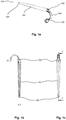
- the guide wire may then be pulled approximately 100 to 150 mm through the wirelock portion 106 to facilitate the locking procedure, in accordance with Fig. 7a .
- the distal end of the guide wire is bent 180 degrees and inserted in the cavity 110 next to the through hole where the guide wire exits, in accordance with Fig. 7b .
- the guide wire may then be pulled in the proximal direction by pulling the part of the guide wire extending from the proximal end of the dilator 100 , creating a sharp bend between the holes in the wirelock portion 106 , that locks the guide wire to the wirelock portion 107 , and thus also to the dilator 100 , in accordance with Fig. 7c .
- a dilator allowing for a more effective and easy to assemble attachment mechanism between the dilator and the guide wire, is obtained, since the pulling force for pulling the dilator 100 through the puncture will only tighten the cooperation between the dilator 100 and the guide wire, without the need of threaded parts and complicated screwing motions during assembly.
- Other ways of fixating the guide wire to the dilator 100 is also possible, without departing from the gist of the present invention.
- the tab 112 facing the two holes - i.e. the through hole/recess and the cavity - of the wirelock portion 106 acts as a stop preventing the guidewire from being pushed out of the cavity 110 , which is also disclosed in Fig. 7c .
- the depth of the cavity 110 may be equal to or greater than the distance from the distal end of the cylindrical body 107 to the tab 112.
- the guidewire-dilator-prosthesis assembly is pulled through the puncture site, dilating the puncture to facilitate the subsequent prosthesis placement.
- the voice prosthesis is pulled through the puncture by the ring 105.
- the tracheal flange of the voice prosthesis is partly folded forward by the ring 105 and partly folded backward by the tissue around the puncture site.
- the ring 105 passes the puncture, the ring 105 is pulled over the tracheal flange of the voice prosthesis, thus forcing said tracheal flange forward and finally unfolding in the trachea.
- the prosthesis safety strap may be cut and the prosthesis may be turned in the correct position.
Claims (8)
- Dilatateur (100, 200, 300) pour insérer une prothèse vocale dans la paroi trachéo-oesophagienne, ladite prothèse vocale comprenant un corps tubulaire et des brides s'étendant radialement vers l'extérieur dans les extrémités dudit corps tubulaire, ledit dilatateur comprenant un corps sensiblement conique (101, 201, 301) ayant une portion de pointe (102) au niveau de l'extrémité proximale et une portion de base (103) au niveau de son extrémité distale, ledit dilatateur (100, 200, 300) comprenant une portion de maintien de prothèse vocale (105, 205, 305) raccordée audit corps sensiblement conique (101, 201, 301) par une portion de raccordement (104, 204, 304), ladite portion de maintien (105, 205, 305) ayant un passage central, caractérisé en ce que
ledit dilatateur (100, 200, 300) comprenant une portion de verrouillage de fil (106), pour verrouiller un fil guide sur celui-ci, ledit passage central étant configuré pour avoir le corps tubulaire de la prothèse vocale positionné au travers, de sorte que les brides s'étendant radialement vers l'extérieur de la prothèse vocale soient sensiblement dépliées de façon proximale audit passage central. - Dilatateur selon la revendication 1, dans lequel ladite portion de raccordement est une sangle (104) et ladite portion de maintien de prothèse vocale est une portion de bague (105).
- Dilatateur selon la revendication 2, dans lequel ladite portion de raccordement est un nombre de nervures flexibles (204) et ladite portion de maintien de prothèse vocale est une portion de bague (205).
- Dilatateur selon la revendication 1, dans lequel ladite portion de raccordement est une portion creuse en forme de soufflet flexible (304), permettant de déplier sensiblement une bride d'une prothèse vocale à l'intérieur.
- Dilatateur selon la revendication 4, dans lequel la portion de raccordement (304), dans un état détendu, s'étend de façon distale depuis le corps conique (301) jusqu'à un diamètre intérieur augmenté, correspondant au diamètre de la bride de la prothèse vocale, où après que la portion de raccordement (304) s'étend de façon distale depuis ledit diamètre intérieur augmenté jusqu'à un diamètre intérieur réduit de la portion de maintien de prothèse vocale (305).
- Dilatateur selon l'une quelconque des revendications 1 à 5, dans lequel le dilatateur est réalisé en un matériau flexible.
- Dilatateur selon l'une quelconque des revendications précédentes, dans lequel le corps sensiblement conique (101, 201, 301) a un trou traversant depuis la portion de pointe (102) jusqu'à la portion de base (103).
- Dilatateur selon la revendication 7, dans lequel le corps conique (101) a un évidement dans la portion de base (103), ledit évidement faisant partie du trou traversant, ledit évidement ayant une aire en coupe plus grande, dans le plan transversal par rapport à l'extension longitudinale du dilatateur, que le trou traversant.
Priority Applications (1)
| Application Number | Priority Date | Filing Date | Title |
|---|---|---|---|
| PL10722147T PL2442753T3 (pl) | 2009-06-16 | 2010-06-16 | Rozszerzacz do wprowadzania protezy głosowej |
Applications Claiming Priority (2)
| Application Number | Priority Date | Filing Date | Title |
|---|---|---|---|
| SE0950462 | 2009-06-16 | ||
| PCT/EP2010/058427 WO2010146071A1 (fr) | 2009-06-16 | 2010-06-16 | Dilatateur pour introduction d'une prothèse vocale |
Publications (2)
| Publication Number | Publication Date |
|---|---|
| EP2442753A1 EP2442753A1 (fr) | 2012-04-25 |
| EP2442753B1 true EP2442753B1 (fr) | 2018-07-18 |
Family
ID=42675913
Family Applications (1)
| Application Number | Title | Priority Date | Filing Date |
|---|---|---|---|
| EP10722147.5A Active EP2442753B1 (fr) | 2009-06-16 | 2010-06-16 | Dilatateur pour introduction d'une prothèse vocale |
Country Status (8)
| Country | Link |
|---|---|
| US (2) | US8721720B2 (fr) |
| EP (1) | EP2442753B1 (fr) |
| JP (1) | JP5647235B2 (fr) |
| CN (1) | CN102458308B (fr) |
| ES (1) | ES2690378T3 (fr) |
| HK (1) | HK1170655A1 (fr) |
| PL (1) | PL2442753T3 (fr) |
| WO (1) | WO2010146071A1 (fr) |
Families Citing this family (2)
| Publication number | Priority date | Publication date | Assignee | Title |
|---|---|---|---|---|
| FR2998162B1 (fr) * | 2012-11-20 | 2016-02-12 | Protip | Dispositif de pose et de depose d'une prothese |
| US11931249B2 (en) | 2021-06-07 | 2024-03-19 | Freudenberg Medical, Llc | Easy voice prosthesis loading insertion device |
Family Cites Families (9)
| Publication number | Priority date | Publication date | Assignee | Title |
|---|---|---|---|---|
| US4808183A (en) * | 1980-06-03 | 1989-02-28 | University Of Iowa Research Foundation | Voice button prosthesis and method for installing same |
| US4439872A (en) * | 1981-10-06 | 1984-04-03 | Henley Cohn Julian L | Apparatus to assist esophageal speech |
| NL1000355C2 (nl) * | 1995-05-12 | 1996-11-13 | Paul Ferdinand Schouwenburg | Stemprothese. |
| SE505552C2 (sv) * | 1995-12-22 | 1997-09-15 | Atos Medical Ab | Sätt för montering av en flänsad rörformig kropp |
| NL1003043C2 (nl) * | 1996-05-06 | 1997-11-07 | Paul Ferdinand Schouwenburg | Set voor het inbrengen van een stemprothese bij gelaryngectomeerden. |
| CN1158110C (zh) * | 2001-12-10 | 2004-07-21 | 周星 | 记忆合金人工喉支撑架 |
| SE528922C2 (sv) | 2004-04-08 | 2007-03-13 | Atos Medical Ab | Förfarande och anordning för säkert insättning och montering av en rörformad anordning i en flexibel vägg samt tillverkningsförfarande för nämnda insättningsanordning |
| US20090036983A1 (en) | 2007-08-01 | 2009-02-05 | Helix Medical, Llc | Voice Prosthesis Gel Cap Loading Tool |
| DE202008000670U1 (de) * | 2008-01-17 | 2008-04-03 | Neubauer, Norbert | Vorrichtung zur Befestigung und zum Anbringen einer rohrförmigen Stimmprothese in eine flexible Wand |
-
2010
- 2010-06-16 US US13/378,590 patent/US8721720B2/en active Active
- 2010-06-16 JP JP2012515471A patent/JP5647235B2/ja active Active
- 2010-06-16 WO PCT/EP2010/058427 patent/WO2010146071A1/fr active Application Filing
- 2010-06-16 EP EP10722147.5A patent/EP2442753B1/fr active Active
- 2010-06-16 PL PL10722147T patent/PL2442753T3/pl unknown
- 2010-06-16 ES ES10722147.5T patent/ES2690378T3/es active Active
- 2010-06-16 CN CN201080026482.8A patent/CN102458308B/zh active Active
-
2012
- 2012-11-15 HK HK12111596.1A patent/HK1170655A1/xx unknown
-
2014
- 2014-04-22 US US14/258,936 patent/US9320596B2/en active Active
Non-Patent Citations (1)
| Title |
|---|
| None * |
Also Published As
| Publication number | Publication date |
|---|---|
| EP2442753A1 (fr) | 2012-04-25 |
| HK1170655A1 (en) | 2013-03-08 |
| WO2010146071A1 (fr) | 2010-12-23 |
| CN102458308A (zh) | 2012-05-16 |
| CN102458308B (zh) | 2015-06-03 |
| PL2442753T3 (pl) | 2018-12-31 |
| ES2690378T3 (es) | 2018-11-20 |
| US20120165936A1 (en) | 2012-06-28 |
| US20140228952A1 (en) | 2014-08-14 |
| US8721720B2 (en) | 2014-05-13 |
| JP2012529944A (ja) | 2012-11-29 |
| JP5647235B2 (ja) | 2014-12-24 |
| US9320596B2 (en) | 2016-04-26 |
Similar Documents
| Publication | Publication Date | Title |
|---|---|---|
| JP5383999B2 (ja) | 内視鏡のための取付装置 | |
| JP5377944B2 (ja) | 胃瘻用シース、シース付きダイレータ、挿入補助具付き胃瘻用シース、胃瘻カテーテルキット | |
| US8945142B2 (en) | Delivery system for implanting nasal ventilation tube | |
| US8480657B2 (en) | Detachable distal overtube section and methods for forming a sealable opening in the wall of an organ | |
| CN108025161B (zh) | 医疗装置的扩张递送系统 | |
| JP2012527930A (ja) | 腹腔鏡のアクセスポート及びポート・スリーブ配置 | |
| US20230123143A1 (en) | Tympanostomy tube and a placement device | |
| KR20160131044A (ko) | 2-부분 무매듭 봉합사 앵커 | |
| BR102012023921B1 (pt) | Insersor para implante e combinação | |
| US9320596B2 (en) | Dilator for inserting a voice prosthesis | |
| CN111356422A (zh) | 鼻旁窦流体进入植入工具、组件、套件及方法 | |
| US20230210512A1 (en) | Knotless anchor inserter tool extraction | |
| EP2477562B1 (fr) | Protecteuer pharyngeal | |
| EP3737275B1 (fr) | Outils et systèmes d'apport de dispositifs | |
| EP3030311B1 (fr) | Déploiement de douille d'ancrage pour dispositifs médicaux implantables | |
| WO2012170860A1 (fr) | Système de pose pour implanter un tube de ventilation nasale | |
| JP2010012052A (ja) | 胃瘻用カテーテル及び胃瘻用カテーテルキット | |
| JP5632943B2 (ja) | 胃瘻用シース、シース付きダイレータ、挿入補助具付き胃瘻用シース、胃瘻カテーテルキット | |
| JP2024060094A (ja) | デバイス送出ツール及びシステム | |
| JP2014121469A (ja) | 胃瘻造設術用拡張器 |
Legal Events
| Date | Code | Title | Description |
|---|---|---|---|
| PUAI | Public reference made under article 153(3) epc to a published international application that has entered the european phase |
Free format text: ORIGINAL CODE: 0009012 |
|
| 17P | Request for examination filed |
Effective date: 20111128 |
|
| AK | Designated contracting states |
Kind code of ref document: A1 Designated state(s): AL AT BE BG CH CY CZ DE DK EE ES FI FR GB GR HR HU IE IS IT LI LT LU LV MC MK MT NL NO PL PT RO SE SI SK SM TR |
|
| DAX | Request for extension of the european patent (deleted) | ||
| 17Q | First examination report despatched |
Effective date: 20141218 |
|
| GRAP | Despatch of communication of intention to grant a patent |
Free format text: ORIGINAL CODE: EPIDOSNIGR1 |
|
| STAA | Information on the status of an ep patent application or granted ep patent |
Free format text: STATUS: GRANT OF PATENT IS INTENDED |
|
| INTG | Intention to grant announced |
Effective date: 20180312 |
|
| RIN1 | Information on inventor provided before grant (corrected) |
Inventor name: MAGNUSSON, RONNY Inventor name: MARGOLIN, GREGORI Inventor name: KARLING, JONAS |
|
| GRAS | Grant fee paid |
Free format text: ORIGINAL CODE: EPIDOSNIGR3 |
|
| GRAA | (expected) grant |
Free format text: ORIGINAL CODE: 0009210 |
|
| STAA | Information on the status of an ep patent application or granted ep patent |
Free format text: STATUS: THE PATENT HAS BEEN GRANTED |
|
| AK | Designated contracting states |
Kind code of ref document: B1 Designated state(s): AL AT BE BG CH CY CZ DE DK EE ES FI FR GB GR HR HU IE IS IT LI LT LU LV MC MK MT NL NO PL PT RO SE SI SK SM TR |
|
| REG | Reference to a national code |
Ref country code: GB Ref legal event code: FG4D |
|
| REG | Reference to a national code |
Ref country code: CH Ref legal event code: EP |
|
| REG | Reference to a national code |
Ref country code: IE Ref legal event code: FG4D |
|
| REG | Reference to a national code |
Ref country code: AT Ref legal event code: REF Ref document number: 1018552 Country of ref document: AT Kind code of ref document: T Effective date: 20180815 |
|
| REG | Reference to a national code |
Ref country code: DE Ref legal event code: R096 Ref document number: 602010051989 Country of ref document: DE |
|
| REG | Reference to a national code |
Ref country code: NL Ref legal event code: FP |
|
| REG | Reference to a national code |
Ref country code: ES Ref legal event code: FG2A Ref document number: 2690378 Country of ref document: ES Kind code of ref document: T3 Effective date: 20181120 |
|
| REG | Reference to a national code |
Ref country code: LT Ref legal event code: MG4D |
|
| REG | Reference to a national code |
Ref country code: AT Ref legal event code: MK05 Ref document number: 1018552 Country of ref document: AT Kind code of ref document: T Effective date: 20180718 |
|
| PG25 | Lapsed in a contracting state [announced via postgrant information from national office to epo] |
Ref country code: LT Free format text: LAPSE BECAUSE OF FAILURE TO SUBMIT A TRANSLATION OF THE DESCRIPTION OR TO PAY THE FEE WITHIN THE PRESCRIBED TIME-LIMIT Effective date: 20180718 Ref country code: IS Free format text: LAPSE BECAUSE OF FAILURE TO SUBMIT A TRANSLATION OF THE DESCRIPTION OR TO PAY THE FEE WITHIN THE PRESCRIBED TIME-LIMIT Effective date: 20181118 Ref country code: AT Free format text: LAPSE BECAUSE OF FAILURE TO SUBMIT A TRANSLATION OF THE DESCRIPTION OR TO PAY THE FEE WITHIN THE PRESCRIBED TIME-LIMIT Effective date: 20180718 Ref country code: BG Free format text: LAPSE BECAUSE OF FAILURE TO SUBMIT A TRANSLATION OF THE DESCRIPTION OR TO PAY THE FEE WITHIN THE PRESCRIBED TIME-LIMIT Effective date: 20181018 Ref country code: SE Free format text: LAPSE BECAUSE OF FAILURE TO SUBMIT A TRANSLATION OF THE DESCRIPTION OR TO PAY THE FEE WITHIN THE PRESCRIBED TIME-LIMIT Effective date: 20180718 Ref country code: FI Free format text: LAPSE BECAUSE OF FAILURE TO SUBMIT A TRANSLATION OF THE DESCRIPTION OR TO PAY THE FEE WITHIN THE PRESCRIBED TIME-LIMIT Effective date: 20180718 Ref country code: NO Free format text: LAPSE BECAUSE OF FAILURE TO SUBMIT A TRANSLATION OF THE DESCRIPTION OR TO PAY THE FEE WITHIN THE PRESCRIBED TIME-LIMIT Effective date: 20181018 Ref country code: GR Free format text: LAPSE BECAUSE OF FAILURE TO SUBMIT A TRANSLATION OF THE DESCRIPTION OR TO PAY THE FEE WITHIN THE PRESCRIBED TIME-LIMIT Effective date: 20181019 |
|
| PG25 | Lapsed in a contracting state [announced via postgrant information from national office to epo] |
Ref country code: HR Free format text: LAPSE BECAUSE OF FAILURE TO SUBMIT A TRANSLATION OF THE DESCRIPTION OR TO PAY THE FEE WITHIN THE PRESCRIBED TIME-LIMIT Effective date: 20180718 Ref country code: LV Free format text: LAPSE BECAUSE OF FAILURE TO SUBMIT A TRANSLATION OF THE DESCRIPTION OR TO PAY THE FEE WITHIN THE PRESCRIBED TIME-LIMIT Effective date: 20180718 Ref country code: AL Free format text: LAPSE BECAUSE OF FAILURE TO SUBMIT A TRANSLATION OF THE DESCRIPTION OR TO PAY THE FEE WITHIN THE PRESCRIBED TIME-LIMIT Effective date: 20180718 |
|
| REG | Reference to a national code |
Ref country code: DE Ref legal event code: R097 Ref document number: 602010051989 Country of ref document: DE |
|
| PG25 | Lapsed in a contracting state [announced via postgrant information from national office to epo] |
Ref country code: CZ Free format text: LAPSE BECAUSE OF FAILURE TO SUBMIT A TRANSLATION OF THE DESCRIPTION OR TO PAY THE FEE WITHIN THE PRESCRIBED TIME-LIMIT Effective date: 20180718 Ref country code: RO Free format text: LAPSE BECAUSE OF FAILURE TO SUBMIT A TRANSLATION OF THE DESCRIPTION OR TO PAY THE FEE WITHIN THE PRESCRIBED TIME-LIMIT Effective date: 20180718 Ref country code: EE Free format text: LAPSE BECAUSE OF FAILURE TO SUBMIT A TRANSLATION OF THE DESCRIPTION OR TO PAY THE FEE WITHIN THE PRESCRIBED TIME-LIMIT Effective date: 20180718 |
|
| PLBE | No opposition filed within time limit |
Free format text: ORIGINAL CODE: 0009261 |
|
| STAA | Information on the status of an ep patent application or granted ep patent |
Free format text: STATUS: NO OPPOSITION FILED WITHIN TIME LIMIT |
|
| PG25 | Lapsed in a contracting state [announced via postgrant information from national office to epo] |
Ref country code: DK Free format text: LAPSE BECAUSE OF FAILURE TO SUBMIT A TRANSLATION OF THE DESCRIPTION OR TO PAY THE FEE WITHIN THE PRESCRIBED TIME-LIMIT Effective date: 20180718 Ref country code: SM Free format text: LAPSE BECAUSE OF FAILURE TO SUBMIT A TRANSLATION OF THE DESCRIPTION OR TO PAY THE FEE WITHIN THE PRESCRIBED TIME-LIMIT Effective date: 20180718 Ref country code: SK Free format text: LAPSE BECAUSE OF FAILURE TO SUBMIT A TRANSLATION OF THE DESCRIPTION OR TO PAY THE FEE WITHIN THE PRESCRIBED TIME-LIMIT Effective date: 20180718 |
|
| 26N | No opposition filed |
Effective date: 20190423 |
|
| PG25 | Lapsed in a contracting state [announced via postgrant information from national office to epo] |
Ref country code: SI Free format text: LAPSE BECAUSE OF FAILURE TO SUBMIT A TRANSLATION OF THE DESCRIPTION OR TO PAY THE FEE WITHIN THE PRESCRIBED TIME-LIMIT Effective date: 20180718 |
|
| PG25 | Lapsed in a contracting state [announced via postgrant information from national office to epo] |
Ref country code: MC Free format text: LAPSE BECAUSE OF FAILURE TO SUBMIT A TRANSLATION OF THE DESCRIPTION OR TO PAY THE FEE WITHIN THE PRESCRIBED TIME-LIMIT Effective date: 20180718 |
|
| REG | Reference to a national code |
Ref country code: CH Ref legal event code: PL |
|
| REG | Reference to a national code |
Ref country code: BE Ref legal event code: MM Effective date: 20190630 |
|
| PG25 | Lapsed in a contracting state [announced via postgrant information from national office to epo] |
Ref country code: TR Free format text: LAPSE BECAUSE OF FAILURE TO SUBMIT A TRANSLATION OF THE DESCRIPTION OR TO PAY THE FEE WITHIN THE PRESCRIBED TIME-LIMIT Effective date: 20180718 |
|
| PG25 | Lapsed in a contracting state [announced via postgrant information from national office to epo] |
Ref country code: IE Free format text: LAPSE BECAUSE OF NON-PAYMENT OF DUE FEES Effective date: 20190616 |
|
| PG25 | Lapsed in a contracting state [announced via postgrant information from national office to epo] |
Ref country code: LI Free format text: LAPSE BECAUSE OF NON-PAYMENT OF DUE FEES Effective date: 20190630 Ref country code: LU Free format text: LAPSE BECAUSE OF NON-PAYMENT OF DUE FEES Effective date: 20190616 Ref country code: BE Free format text: LAPSE BECAUSE OF NON-PAYMENT OF DUE FEES Effective date: 20190630 Ref country code: CH Free format text: LAPSE BECAUSE OF NON-PAYMENT OF DUE FEES Effective date: 20190630 |
|
| PG25 | Lapsed in a contracting state [announced via postgrant information from national office to epo] |
Ref country code: PT Free format text: LAPSE BECAUSE OF FAILURE TO SUBMIT A TRANSLATION OF THE DESCRIPTION OR TO PAY THE FEE WITHIN THE PRESCRIBED TIME-LIMIT Effective date: 20181118 |
|
| PG25 | Lapsed in a contracting state [announced via postgrant information from national office to epo] |
Ref country code: CY Free format text: LAPSE BECAUSE OF FAILURE TO SUBMIT A TRANSLATION OF THE DESCRIPTION OR TO PAY THE FEE WITHIN THE PRESCRIBED TIME-LIMIT Effective date: 20180718 |
|
| PG25 | Lapsed in a contracting state [announced via postgrant information from national office to epo] |
Ref country code: MT Free format text: LAPSE BECAUSE OF FAILURE TO SUBMIT A TRANSLATION OF THE DESCRIPTION OR TO PAY THE FEE WITHIN THE PRESCRIBED TIME-LIMIT Effective date: 20180718 Ref country code: HU Free format text: LAPSE BECAUSE OF FAILURE TO SUBMIT A TRANSLATION OF THE DESCRIPTION OR TO PAY THE FEE WITHIN THE PRESCRIBED TIME-LIMIT; INVALID AB INITIO Effective date: 20100616 |
|
| PG25 | Lapsed in a contracting state [announced via postgrant information from national office to epo] |
Ref country code: MK Free format text: LAPSE BECAUSE OF FAILURE TO SUBMIT A TRANSLATION OF THE DESCRIPTION OR TO PAY THE FEE WITHIN THE PRESCRIBED TIME-LIMIT Effective date: 20180718 |
|
| REG | Reference to a national code |
Ref country code: GB Ref legal event code: 732E Free format text: REGISTERED BETWEEN 20230216 AND 20230222 |
|
| REG | Reference to a national code |
Ref country code: DE Ref legal event code: R081 Ref document number: 602010051989 Country of ref document: DE Owner name: COLOPLAST A/S, DK Free format text: FORMER OWNER: ATOS MEDICAL AB, HOERBY, SE Ref country code: DE Ref legal event code: R082 Ref document number: 602010051989 Country of ref document: DE |
|
| REG | Reference to a national code |
Ref country code: NL Ref legal event code: PD Owner name: COLOPLAST A/S; DK Free format text: DETAILS ASSIGNMENT: CHANGE OF OWNER(S), ASSIGNMENT; FORMER OWNER NAME: ATOS MEDICAL AB Effective date: 20230327 |
|
| REG | Reference to a national code |
Ref country code: ES Ref legal event code: PC2A Owner name: COLOPLAST A/S Effective date: 20230529 |
|
| PGFP | Annual fee paid to national office [announced via postgrant information from national office to epo] |
Ref country code: NL Payment date: 20230626 Year of fee payment: 14 Ref country code: FR Payment date: 20230626 Year of fee payment: 14 Ref country code: DE Payment date: 20230626 Year of fee payment: 14 |
|
| PGFP | Annual fee paid to national office [announced via postgrant information from national office to epo] |
Ref country code: PL Payment date: 20230602 Year of fee payment: 14 |
|
| PGFP | Annual fee paid to national office [announced via postgrant information from national office to epo] |
Ref country code: IT Payment date: 20230620 Year of fee payment: 14 Ref country code: GB Payment date: 20230627 Year of fee payment: 14 Ref country code: ES Payment date: 20230703 Year of fee payment: 14 |