EP2442184A1 - Verfahren zur Bestimmung einer zeitvariablen Temperatur von mindestens einer temperaturkritischen Komponente - Google Patents
Verfahren zur Bestimmung einer zeitvariablen Temperatur von mindestens einer temperaturkritischen Komponente Download PDFInfo
- Publication number
- EP2442184A1 EP2442184A1 EP10290560A EP10290560A EP2442184A1 EP 2442184 A1 EP2442184 A1 EP 2442184A1 EP 10290560 A EP10290560 A EP 10290560A EP 10290560 A EP10290560 A EP 10290560A EP 2442184 A1 EP2442184 A1 EP 2442184A1
- Authority
- EP
- European Patent Office
- Prior art keywords
- temperature
- temperature value
- value
- critical component
- time interval
- Prior art date
- Legal status (The legal status is an assumption and is not a legal conclusion. Google has not performed a legal analysis and makes no representation as to the accuracy of the status listed.)
- Withdrawn
Links
Images

Classifications
-
- G—PHYSICS
- G03—PHOTOGRAPHY; CINEMATOGRAPHY; ANALOGOUS TECHNIQUES USING WAVES OTHER THAN OPTICAL WAVES; ELECTROGRAPHY; HOLOGRAPHY
- G03G—ELECTROGRAPHY; ELECTROPHOTOGRAPHY; MAGNETOGRAPHY
- G03G21/00—Arrangements not provided for by groups G03G13/00 - G03G19/00, e.g. cleaning, elimination of residual charge
- G03G21/20—Humidity or temperature control also ozone evacuation; Internal apparatus environment control
-
- G—PHYSICS
- G03—PHOTOGRAPHY; CINEMATOGRAPHY; ANALOGOUS TECHNIQUES USING WAVES OTHER THAN OPTICAL WAVES; ELECTROGRAPHY; HOLOGRAPHY
- G03G—ELECTROGRAPHY; ELECTROPHOTOGRAPHY; MAGNETOGRAPHY
- G03G15/00—Apparatus for electrographic processes using a charge pattern
- G03G15/20—Apparatus for electrographic processes using a charge pattern for fixing, e.g. by using heat
- G03G15/2003—Apparatus for electrographic processes using a charge pattern for fixing, e.g. by using heat using heat
- G03G15/2014—Apparatus for electrographic processes using a charge pattern for fixing, e.g. by using heat using heat using contact heat
- G03G15/2039—Apparatus for electrographic processes using a charge pattern for fixing, e.g. by using heat using heat using contact heat with means for controlling the fixing temperature
-
- G—PHYSICS
- G03—PHOTOGRAPHY; CINEMATOGRAPHY; ANALOGOUS TECHNIQUES USING WAVES OTHER THAN OPTICAL WAVES; ELECTROGRAPHY; HOLOGRAPHY
- G03G—ELECTROGRAPHY; ELECTROPHOTOGRAPHY; MAGNETOGRAPHY
- G03G2215/00—Apparatus for electrophotographic processes
- G03G2215/00362—Apparatus for electrophotographic processes relating to the copy medium handling
- G03G2215/00535—Stable handling of copy medium
- G03G2215/00717—Detection of physical properties
- G03G2215/00772—Detection of physical properties of temperature influencing copy sheet handling
Definitions
- the invention relates to a method for determining a time-varying temperature of at least one temperature-critical component of an electrophotography apparatus according to the preamble of claim 1.
- the electrophotography apparatus can especially be arranged as a laser printer, a laser fax device and/or as a laser copying machine.
- the electrophotography apparatus is arranged to be operated in at least two operating modes.
- the electrophotography apparatus comprises at least one temperature-critical component, which temperature-critical component can overheat depending on the operating mode of the electrophotography apparatus in such a way that it has a temperature which is higher than the maximum permissible operating temperature of this component in the respectively current operating mode of the electrophotography apparatus.
- a first component can be the temperature-critical component in a first one of the operating modes
- a second component can be the temperature-critical component in a second one of the operating modes.
- the time-varying temperature of the temperature-critical component must be determined.
- the temperature-critical component or the temperature-critical components of the electrophotography apparatus are temperature-monitored.
- the electrophotography apparatus comprises a temperature-monitoring sensor for each temperature-critical component, thus causing additional production costs, additional space requirements and additional weight, which is therefore uneconomical.
- the temperature of the temperature-critical component is determined by means of a simulation, which means that it is therefore simulated instead of being measured directly, with said temperature of the temperature-critical component being determined during operation of the electrophotography apparatus with sufficient precision and without any additional temperature-monitoring sensor for monitoring the temperature of the temperature-critical component in order to avoid overheating the temperature-critical component or recognize the same in a timely fashion. It is advantageous that the measuring effort is low and it is possible to omit these additional temperature-monitoring sensors.
- the advantageous aspect is that the temperature of the at least one temperature-critical component can be determined and upon exceeding a temperature threshold value a signal can be generated which can further trigger an action, e.g. a temporary switch-off of the electrophotography apparatus or a temporary activation of an active cooling system. Simple protection from overheating can be ensured by means of the method for determining a time-varying temperature of at least one temperature-critical component.
- the invention further relates to a computer program means for executing this method and a data media comprising the computer program means.
- the invention further relates to an electrophotography apparatus, in which electrophotography apparatus this method is used in order to simulate the time-varying temperature of at least one temperature-critical component of the electrophotography apparatus by means of computer-determined temperature values.
- Figs. 1 to 5 schematically show graphical representations of a time-varying simulated temperature of at least one temperature-critical component of an electrophotography apparatus, which simulated temperature is determined by means of a method for determining the time-varying temperature of at least one temperature-critical component of the electrophotography apparatus, especially a laser printer, a laser fax device and/or a laser copying machine, with the electrophotography apparatus being arranged to be operated in at least two operating modes 21 ⁇ 27.
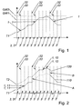
- the time-varying temperature of the temperature-critical component is determined in temporally successive time intervals 3 in such a way that substantially in each of the time intervals 3 a temperature value 1 of the temperature-critical component is determined at the end 33 of this time interval 3 depending on the temperature value 1 of the temperature-critical component at the beginning 32 of said time interval 3, an estimated ambient temperature value, and the operating mode of the operating modes 21 ⁇ 27, in which operating mode the electrophotography apparatus is operated during said time interval 3, and the temperature value 1 of the temperature-critical component and the estimated ambient temperature value at the beginning 32 of the first time interval 31 of the time intervals 3 are determined.
- the temperature of the temperature-critical component is determined by means of a simulation, with which the temperature is simulated in this sense by determining temperature values 1 instead of directly measuring the temperature of the temperature-critical component.
- the temperature of the temperature-critical component is determined during the operation of the electrophotography apparatus without any additional temperature-monitoring sensor for monitoring the temperature of the temperature-critical component in order to avoid overheating the temperature-critical component or recognizing the same in a timely fashion. It is advantageous that the measuring effort is low and it is possible to omit a large number of temperature-monitoring sensors for monitoring the temperature of the at least one temperature-critical component.
- the temperature of the at least one temperature-critical component can be determined in a sufficiently precise way and upon reaching, exceeding or falling below a temperature threshold value GW1, GW2 a signal can be generated which can further trigger an action, especially a temporary switch-off of the electrophotography apparatus or a temporary activation of an active cooling system, especially comprising a fan, of the electrophotography apparatus.
- a temperature threshold value GW1, GW2 can be provided, especially two thereof, with an action being triggered for each of the temperature threshold values GW1, GW2. Simple protection from overheating can be ensured by means of the method for determining a time-varying temperature of at least one temperature-critical component in order to prevent (especially long) overheating of the temperature-critical component.
- the method for determining the time-varying temperature and the subsequently described further developments of this method can thus be comprised by a method for overheating protection of the at least one temperature-critical component. It is further provided in the method for overheating protection that a signal is generated when the temperature reaches, exceeds or falls below a predeterminable temperature threshold value GW1, GW2.
- the method can be used for retrofitting conventional electrophotography apparatuses, so that their reliability, operational dependability and/or their service life can be increased, with it being provided that the electrophotography apparatus comprises at least one memory and computer program means for performing the method.
- the electrophotography apparatus can especially comprise a start-phase operating mode 21, at least one readiness operating mode 22-24, an error operating mode 25 for the case of a malfunction of the electrophotography apparatus, at least one active operating mode 26 and one cooling operating mode 27.
- the start-phase operating mode 21 is usually performed directly after the activation of the voltage supply of the electrophotography apparatus.
- the at least one readiness operating mode 22-24 can especially comprise a preheating operating mode 22 for preheating a fixing unit of the electrophotography apparatus, a sleep operating mode 23 for saving power, and a readiness operating mode 24.
- the electrophotography apparatus prints a recording medium such as paper in the active operating mode 26.
- the fixing unit is unheated in the cooling operating mode 27 and an active cooling system, especially comprising a fan, is driven.
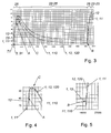
- the operating modes 21-27 are shown schematically in Fig. 7 , with the arrows shown in Fig. 7 schematically showing some of the possible changes from one of the operating modes 21-27 to other of the operating modes 21-27.
- the electrophotography apparatus is switched to the cooling operating mode 27, which means it changes to this mode, with a change being made from the error operating mode 25 or active operating mode 26 to the cooling operating mode 27 when the temperature value 1 is larger than or equal to the second temperature threshold value GW2 in the error operating mode 25 or in the active operating mode 26. It can further be provided that the electrophotography apparatus is switched from the cooling operating mode 27 to the error operating mode 25 or active operating mode 26, which means it changes thereto, when the temperature value 1 in the cooling operating mode 27 is smaller than or equal to the first temperature threshold value GW1.
- the speed of the fan of the active cooling system is controlled or adjusted depending on the temperature value 1.
- the first time interval 31 is arranged and performed directly after the end of the start-phase operating mode 21, wherein the first time interval 31 can be especially arranged and performed in the readiness operating mode 24.
- the time intervals 3 which follow one another in a directly successive manner over time are entered along the x-axis in Figs. 1 to 3 and 6 , starting with the first time interval 31.
- the x-axis corresponds to the time axis.
- all time intervals can have a substantially constant duration.
- each time interval 3 of the time intervals 3 can substantially be approximately one second for example.
- the temperature of the temperature-critical component is entered on the y-axis in Figs. 1 to 3 and 6 .
- a quantity characterizing this temperature can be entered on the y-axis.
- each operating mode of the operating modes 21-27 there is precisely one temperature-critical component, which temperature-critical component tends to be the fastest towards overheating in this operating mode.
- different components of the electrophotography apparatus can be the at least one temperature-critical component.
- the electrophotography apparatus can be arranged in such a way that in a duplex printing mode of the operating modes 21-27 a component comprised by a duplex path or a module comprised by the duplex path is the temperature-critical component and that in single-page printing mode of the operating modes 21-27 a component comprised by an output path or a module comprised by the duplex path is the temperature-critical component.
- a first component of the electrophotography apparatus can be the temperature-critical component and after the change in the operating mode a second component of the electrophotography apparatus can be the temperature-critical component. Since merely the temperature of the respective temperature-critical component is determined continuously, it can be ensured in this change of the operating mode that the temperature value 1 of the temperature-critical component determined after this change, which is then the second component, is in any case higher than the actual temperature of the second component at this point in time because the second component was not temperature-critical before the change, i.e. in the operating mode directly preceding the change. The method can thus ensure an especially reliable protection from overheating of the temperature-critical component.
- the time intervals 3 which follow one another in a directly successive manner over time can be numbered continuously with integers n, starting with the first time interval 31, with n being an integral number larger than zero.
- the temperature change of the temperature-critical component occurs at constant ambient temperature usually according to exponential functions or logarithm functions, so that the function f in the diagram can be arranged over sections according to the natural exponential function, i.e. the exponential function on the basis of the Euler's number, or the natural logarithm, as is schematically shown in Fig. 3 .
- the advantageous aspect is that the exponential functions and logarithm functions are determined completely by a few parameters and require little computing power during calculation.
- a first approximation of function f especially for time intervals 3 which have a duration that is short for temperature changes of the temperature-critical component such as one second for example, that the function f is approximated by a temperature gradient, which temperature gradient depends on T n , the estimated ambient temperature value and the respective operating mode 21-27.
- the functional value of the first function of the respective time interval 3, e.g. the n th time interval 3, is then obtained as the temperature gradient multiplied by the duration of this time interval 3.
- the advantageous aspect is that the temperature gradient is determined by very few parameters and the functional value of the function f for each time interval 3 can thus be determined with especially little computing power.
- the parameters describing the function f can be predetermined for each of all operating modes 21-27 and can be stored in advance as a parameter quantity, especially in a flash memory and/or read-only memory of the electrophotography apparatus.
- determining the functional value of the function f it is then possible for determining the functional value of the function f to choose at least one parameter from the parameter quantity depending on the operating mode of the operating modes 21-27, in which operating mode the electrophotography apparatus is operated during this time interval 3, and to determine a time constant depending on the temperature value 1 of the temperature-critical component at the beginning 32 of this time interval 3 and an estimated ambient temperature value, and to calculate the functional value of function f.
- Figs. 1 to 5 The step-by-step determination of the temperature value 1 of the temperature-critical component by means of the directly successively following time intervals 3 is shown schematically in Figs. 1 to 5 . Since the temperature values 1 are calculated step-by-step in the directly successively following time intervals 3, this step-by-step determination can be designated as step-by-step calculation of the temperature of the temperature-critical component.
- Fig. 1 schematically shows a number of the directly successively following time intervals 3, starting with the first time interval 31 which is shown in the drawing adjacent to the y-axis.
- the estimated ambient temperature value is determined by means of a first measured value 4 of a first temperature sensor for measuring a first module temperature of a first module of the electrophotography apparatus. It is advantageous that the first temperature sensor which is determined primarily for measuring and/or monitoring the temperature of the first module is also used for determining the estimated ambient temperature value, so that an additional temperature sensor for determining the estimated ambient temperature value can be omitted.
- the housing can be the first module for example.
- the power supply unit is the first module.
- the first temperature sensor is provided for safety reasons in order to monitor the temperature of the power supply unit and to determine an electric and/or electronic overload of the power supply unit in the case of a malfunction of the electrophotography apparatus, with the first temperature sensor measuring the temperature of the heat sink of the power supply unit, especially the heat sink of the voltage rectifier diodes.
- the first temperature sensor is designedate the first temperature sensor as an electronic overload temperature sensor.
- the estimated ambient temperature value is chosen from a predetermined first quantity of predetermined first values T1, T2 depending on the first measured value 4.
- the first quantity comprises at least two first values T1, T2.
- the first quantity comprises at least three or at least four first values T1, T2.
- the parameters determining the function f can be predetermined for each of the first values T1, T2 for each of the operating modes and can be stored in advance as a parameter quantity in the flash memory and/or in the read/only memory of the electrophotography apparatus. It can then be provided for determining the functional value of the first function f that in each time interval 3, e.g. in the n th time interval 3, at least one parameter is chosen from the parameter quantity depending on the operating mode of the operating modes 21-27, in which operating mode the electrophotography apparatus is operated during this time interval 3, and for each of the first values T1, T2, and the functional values of the function f are determined for each of the first values T1, T2.
- temperature value curves 110, 120 are determined for the temperature-critical component for each of the first value T1, T2.
- the advantageous aspect is that depending on the estimated ambient temperature value valid for this time interval 3 the temperature value 1 of the temperature-critical component can be chosen in the respective time interval 3 from these several time value curves 110, 120.
- the temperature value 1 of the temperature-critical component at the beginning 32 of this time interval 3 e.g. the n th time interval 3
- Fig. 6 schematically shows two possible curve progressions 41, 42 of the first measured value 4 that are possible in operation of the electrophotography apparatus, as such measured values 4 can be measured by the first temperature sensor of the power supply unit during operation.
- the temperature of the heat sink of the voltage rectifier diodes of the power supply unit is measured, with the temperature of the heat sink of the electrophotography apparatus being substantially equal to the ambient temperature when the electrophotography apparatus is switched on as long as the electrophotography apparatus was switched off for a sufficient period of time.
- the time intervals 3 are entered on the x-axis of the diagram in Fig. 6 in a directly successive manner. It can especially be provided that each time interval 3 of the time intervals 3 has substantially the same duration.
- the bottom curve progression 41 of the two curve progressions 41, 42 show the time-varying first measured values 4 at an ambient temperature of 25°C, which is an ambient temperature that is normal for the operation of the electrophotography apparatus, and depending on a time-varying power consumption of the electrophotography apparatus.
- the upper curve progression 42 of the two curve progressions 41, 42 shows the time-varying first measured value 4 at an ambient temperature of 35°C, which is an ambient temperature which is high for the operation of the electrophotography apparatus, and the time-varying power consumption of the electrophotography apparatus depending on the same, with the two curve progressions 41, 42 being substantially congruent.
- Fig. 6 shows the two curve progressions 41, 42 in the case that the electrophotography apparatus is switched off up to the first point in time X1 and is switched on at the point in time X1.
- the start-phase operating mode 21 is executed first.
- the electrophotography apparatus is then in the readiness operating mode 22-24 up to the point in time X2 according to this example, with the first measured value 4 rising over time, with the first measured value 4 approaching in an asymptotic manner the equilibrium measured value 44, which equilibrium measured value 44 depends on the ambient temperature and the power consumption of the electrophotography apparatus in the readiness operating mode 22-24.
- the printing process is started at the point in time X2, with the system changing from the readiness operating mode 22-24 to the printing operating mode 26.
- the electrophotography apparatus consumes more power than in the readiness operating mode 22-24, so that more exhaust heat needs to be discharged by the heat sink of the voltage rectifier diodes, so that the temperature of the heat sink of the voltage rectifier diodes of the power supply unit and the first measured value 4 of the equilibrium measured value 44 rise.
- the electrophotography apparatus consumes less current again, so that less exhaust heat needs to be discharged, so that the temperature of the heat sink of the voltage rectifier diodes of the power supply unit and the first measured value 4 decrease again in the direction of the equilibrium measured value 44, with the first measured value now approaching the equilibrium measured value 44 from above in an asymptotic manner.
- the electrophotography apparatus is operated from a third point in time X3 over a prolonged period in the readiness operating mode 22-24 and finally switched off at a fourth point in time X4.
- the electrophotography apparatus is provided for long-term and permanent operation, especially for at least 8 hours, preferably for at least 24 hours, more preferably for at least one week.
- the ambient temperature can change.
- an office temperature can be approx. 25°C in the morning, which corresponds to a normal ambient temperature, and rise during the afternoon of the same day to 35°C, which corresponds to a high ambient temperature.
- a temperature value correction A, B is advantageous in operation of the electrophotography apparatus in order to ensure a sufficiently precise calculation of the time-varying temperature of the temperature-critical component.
- a temperature value correction A, B of the temperature value 1 can further be performed during the operation of the electrophotography apparatus, triggered by the renewed determination of the estimated ambient temperature value during operation of the electrophotography apparatus.
- Said temperature value correction A, B can especially be performed directly subsequently to the determination of the estimated ambient temperature value during the operation of the electrophotography apparatus, as will be described below in closer detail.
- the estimated ambient temperature value is chosen again from the quantity of the first values T1, T2, in that the first value T1, T2 closest to the ambient temperature is chosen as the estimated ambient temperature value.
- the estimated ambient temperature value is determined again when the electrophotography apparatus is operated in the readiness operating mode 22-24 of the operating modes 21-27 and when all components of the electrophotography apparatus are substantially in a temperature equilibrium.
- the electrophotography apparatus must be in the readiness operating mode 22-24 for a predetermined minimum period of time, which minimum period of time is dependent on how long the electrophotography apparatus was operated in the operating mode 26 directly beforehand. It can be provided for example that the minimum duration is 1 hour when 100 pages were printed before, and the minimum duration is 6 hours when 500 pages were printed before.
- the values for the minimum duration can be predetermined for different situations and stored in advance in the electrophotography apparatus.
- the power consumption of the electrophotography apparatus usually hardly varies in the readiness operating mode 22-24.
- the first measured value 4 is thus substantially constant, thus substantially corresponds to an equilibrium measured value 44.
- the ambient temperature can thus be derived by means of the first measured value 4 corresponding substantially to the equilibrium measured value 44, with the first measured value 4 being larger by a predetermined amount than the ambient temperature, so that the estimated ambient temperature value can be determined again with high precision by taking into account this precisely prior known value.
- the temperature value correction A, B of the temperature value 1 is triggered, especially triggered in a substantially direct way.
- the temperature value 1 is adjusted according to the renewed determined (thus updated) estimated ambient temperature value.
- the estimated ambient temperature value is determined again when the electrophotography apparatus is operated in the active operating mode 26 of the operating modes 21-27 and when the first measured value 4 is larger than an operating-mode update value W.
- the operating-mode update value W can especially be chosen in a predetermined manner in such a way that the first measured value 4 merely reaches or exceeds the operating-mode update value W in the active operating mode 26 of the electrophotography apparatus when the electrophotography apparatus is operated at a high ambient temperature, e.g. approximately 35°C.
- the estimated ambient temperature value can be determined again.
- the estimated ambient temperature value can again be chosen from the quantity of the first values T1, T2 in that the ambient temperature is chosen as the estimated ambient temperature value according to the nearest of the first values.
- the temperature value correction A, B of the temperature value 1 is triggered by the renewed determination of the estimated ambient temperature value in the active operating mode 26, especially that it is triggered directly.
- the temperature value 1 is then adjusted to the newly prevailing ambient temperature conditions according to the estimated ambient temperature value which is determined again and thus updated.
- a temperature value correction A, B of the temperature value 1 is triggered, and is especially triggered in a substantially direct way, both by the renewed determination of the estimated ambient temperature value in the active operating mode 26 and both by the renewed determination of the estimated ambient temperature value in the readiness operating mode 22-24.
- the method can comprise a combination of the first and second further development of the method in order to determine the estimated ambient temperature value during the operation again. It is advantageous that the estimated ambient temperature value in different operating modes 21-27 is determined again repeatedly, so that temperature changes in the ambient temperature can be followed reliably.
- the estimated ambient temperature value is determined, and that it is especially determined again, when the operating mode 21-27 in which the electrophotography apparatus is operated is changed.
- the change of the operating mode 21-27 during the operation of the electrophotography apparatus can trigger the renewed determination of the estimated ambient temperature value in an especially simple way. This time of determination is especially advantageous and requires little computing power in combination with the first further development of the invention.
- the temperature value 1 of the temperature-critical component is determined at the beginning 32 of the first time interval 31 of the time intervals 3 by means of a second measured value of a second temperature sensor for measuring a second module temperature of a second module, especially a fixing unit, of the electrophotography apparatus.
- the temperature value 1 of the temperature-critical component is chosen at the beginning 32 of the first time interval 31 of the time intervals 3 from a predetermined quantity of predetermined second values depending on the first measured value 4 and/or the second measured value.
- the first measured value 4 and/or the second measured value, especially the first measured value 4 and the second measured value are sorted into measured value classes during the determination. It can especially be provided that it is provided as a result for the respective of the two measured values whether the respective of the two measured values is low, medium or high in comparison with the values of the respective measured value which are common during operation.
- a low measured value 4 will especially be present when a measurement is made below approx. 40°C by means of the first temperature sensor.
- a medium first measured value 4 can especially be present when a measurement is made between approx. 40°C and approx. 55°C by means of the first temperature sensor.
- a high measured value can especially be present when more than approx. 55°C is measured by means of the first temperature sensor.
- a low second measured value can especially be present when a value is measured beneath approx. 100°C by means of the second temperature sensor.
- a medium second measured value can especially be present when a value between approx. 100°C and approx. 150°C is measured by means of the first temperature sensor.
- a high second measured value can especially be present when a value of more than approx. 150°C is measured by means of the second temperature sensor. This leads to nine possible combinations of the first measured value and/or the second measured value.
- the predetermined quantity comprises nine predetermined second values, so that the temperature value 1 of the temperature-critical component is chosen at the beginning 32 of the first time interval 31 of the time intervals 3 from these nine predetermined second values depending on the first and/or the second measured value.
- the time-varying temperature of the temperature-critical component is determined in directly successive time intervals 3 over time in one of the operating modes 21-27 during the operation of the electrophotography apparatus in such a way that substantially in each time interval 3, especially the n th time interval 3, of the time intervals 3 a first temperature value 11 of the temperature-critical component is determined at the end 33 of said time interval 3 depending on the first temperature value 11 of the temperature-critical component at the beginning 32 of said time interval 3, especially the n th time interval 3, of the predetermined first first value T1 and the operating mode of the operating modes 21-27, in which operating mode the electrophotography apparatus is operated during said time interval 3, and a second temperature value 12 of the temperature-critical component is determined at the end 33 of said time interval 3 depending on the second temperature value 12 of the temperature-critical component at the beginning 32 of said time interval 3, the predetermined second first value T2 and the operating mode of the operating modes 21-27, in which operating mode the electrophotography apparatus is operated during said time interval 3, and
- the first temperature 11 of the temperature-critical component can especially be chosen as the temperature value 1 of the temperature-critical component when the estimated ambient temperature value is nearer to the first first value T1 than the second first value T2.
- the advantageous aspect is that continuously both the first temperature values 11 and the second temperature values 12 are available for the choice of the temperature value 1 of the temperature-critical component.
- the first temperature value 11 is chosen as the temperature value 1 when the estimated ambient temperature value is nearer to the first first value T1 than the second first T2
- the second temperature value 12 is chosen as the temperature value 1 of the temperature-critical component when the estimated ambient temperature value is nearer to the second first value T2 than the first first value T1.
- a third temperature value, especially a third and fourth temperature value, of the temperature-critical component is determined at the end 33 of this time interval 3 depending on the third temperature value, especially the third and fourth temperature value, of the temperature-critical component at the beginning 32 of said time interval 3, a predetermined third first value, especially a third and fourth first value, and the operating mode of the operating modes 21-27, in which operating mode the electrophotography apparatus is operated during said time interval 3, that the estimated ambient temperature value is compared with the first to fourth first values, and that the value is chosen as temperature value 1 of the temperature-critical component from the quantity of the first to fourth temperature value which is associated to the one of the first to fourth first value which comes closest to the estimated ambient temperature value.
- Figs. 2 to 5 show the discrete temperature value corrections A, B illustrated on the basis of an example of the change of the ambient temperature over time, with the ambient temperature first being low, e.g. approx. 25°C, then rising to a high ambient temperature, e.g. to approx. 35°C, and then dropping again to a low ambient temperature, e.g. to approx. 25°C.
- a temperature development can occur during a work day for example.
- both the first temperature value 11 of the temperature-critical component and the second temperature value 12 of the temperature-critical component can advantageously be determined in each of the time intervals 3 and the temperature value 1 of the temperature-critical component can be chosen from the first temperature value 11 and the second temperature value 12.
- the temporally successive first temperature values 11 lead to a first temperature value curve 110.
- the temporally successive second temperature values 11 lead to a second temperature value curve 120.
- Fig. 3 schematically shows the first temperature value curve 110 and the second temperature value curve 120, as can be determined over the course of a work day under office conditions by means of the method on the basis of one of many possible application examples of the electrophotography apparatus.
- the electrophotography apparatus is switched on in the morning. Once the electrophotography apparatus switches to a printing operating mode 26 and is operated in the printing operating mode 26, the first temperature value curve 110 and the second temperature value curve 120 will rise. While the electrophotography apparatus is in this printing operating mode 26, the estimated ambient temperature value changes, so that the first temperature value correction A is performed.
- the printing operating mode 26 continues, so that the activation of active cooling becomes necessary, so that the electrophotography apparatus is operated in an active-cooling printing operating mode C which is comprised by the printing operating mode 26 and in which active-cooling printing operating mode C the active cooling system, and especially the fan, is repeatedly activated during printing.
- the electrophotography apparatus changes from the printing operating mode 26 into the readiness operating mode 22-24.
- the readiness operating mode 22-24 the first temperature value curve 110 and the second temperature value curve 120 decrease exponentially up to a point in time at which a new printing process is started and the electrophotography apparatus changes again to the printing operating mode 26.
- a renewed determination of the estimated ambient temperature value is triggered by this change of the operating mode from readiness operating mode 22-24 to the printing operating mode 26, with the estimated ambient temperature value changing in such a way that the second temperature value correction B is performed.
- the printing operating mode 26 which follows the second temperature value correction B, the first temperature value curve 110 and the second temperature value curve 120 increase again.
- This printing operating mode 26 is short according to the application example of the electrophotography apparatus, so that the active cooling system is not activated.
- the electrophotography apparatus changes again to the readiness operating mode 22-24 and is switched off after a further time interval.
- Fig. 4 shows a detail of the section of the diagram of Fig. 3 , in which section the substantially discrete change of the temperature value 1 of the temperature-critical component which is caused by the first temperature value correction A occurs at the time of the first temperature value correction A.
- Fig. 5 shows a detail of the section of the diagram of Fig. 3 , in which section the substantially discrete change of the temperature value 1 of the temperature-critical component which is caused by the second temperature value correction B occurs at the time of the second temperature value correction B.
- the first temperature value 11 is chosen as the first temperature value 1 from the time of switching on the electrophotography apparatus until the first temperature value correction A in each time interval 3 by means of the respectively determined estimated ambient temperature value.
- the first temperature value curve 110 is switched to active and the second temperature value curve 120 is switched to passive in a first time range, which first time range lasts from the time of switching on the electrophotography apparatus up to the first temperature correction value A.
- the second temperature value 12 is chosen as the first temperature value 1 in each time interval 3 by means of the respectively determined estimated ambient temperature value.
- the second temperature value curve 120 is switched to active and the first temperature value curve 110 is switched to passive in a second time range, which second time range lasts from the first temperature value correction A to the second temperature value correction B.
- the first temperature value 11 is chosen as the first temperature value 1 in each time interval 3 by means of the respectively determined estimated ambient temperature value.
- the first temperature value curve 110 is switched to active and the second temperature value curve 120 is switched to passive in a third time range, which third time range lasts from the second temperature value correction B, especially up a third temperature value correction or a deactivation of the electrophotography apparatus.
- the active and passive switching of the first temperature value curve 110 and the second temperature value curve 120 is shown in Figs. 2 , 4 and 5 schematically by means of the unbroken and broken line sections of the first and second temperature value curve 110, 120.
- the temperature value 1 of the temperature-critical component is stored at the end 33 of said time interval 3 in a flash memory as a stored temperature value.
- the flash memory of the electrophotography apparatus is provided so that the stored temperature value remains stored during an interruption in the power supply of the electrophotography apparatus, e.g. triggered by switching off the electrophotography apparatus.
- the flash memory is a non-volatile memory.
- the advantageous aspect is that the stored temperature value, especially the last stored temperature value, remains stored after the switch-off and renewed switch-on of the electrophotography apparatus and can thus be used further for determining the temperature value 1 of the temperature-critical component.
- a volatile memory e.g. a volatile main memory of the electrophotography apparatus, loses its memory content upon interruption of the power supply to the electrophotography apparatus.
- the temperature value 1 of the temperature-critical component is stored at the end 33 of each x th time interval 3 in the flash memory as a stored temperature value, with x being an integral number larger than 1, especially larger than 10, preferably larger than 100. It can thus be ensured that the flash memory is written in regular intervals, but not at the end 33 of each time interval 3, which thus can considerably increase the life of the flash memory and can ensure an arrangement of the method that requires little computing power.
- the temperature value 1 of the temperature-critical component at the end 33 of this time interval 3 is compared with the stored temperature value last stored in the flash memory and is then merely stored in the flash memory if the temperature value 1 of the temperature-critical component differs at the end 33 of this time interval 3 from the finally stored temperature value by at least a predetermined flash update value. It can thus also be prevented that the temperature value 1 of the temperature-critical component is stored at the end 33 of each time interval 3 in the flash memory, which thus can also increase the life of the flash memory and can ensure an arrangement of the method that requires little computing power.
- the frequency is influenced by the choice of the flash update value with which the temperature value 1 of the temperature-critical component is stored in the flash memory at the end 33 of each of the time intervals 3.
- the flash update value can be predetermined especially between 2°C and 6°C, especially approx. 4°C.
- a new cycle of the time intervals 3 begins, starting again with the first time interval 31 of the time intervals 3, with the temperature of the temperature-critical component not being able to increase in the deactivated state of the electrophotography apparatus, which means in the normal state and without any malfunctions.
- the electrophotography apparatus comprises a real-time clock. The duration can be determined by means of the real-time clock after the renewed switch-on of the electrophotography apparatus as to how long the electrophotography apparatus was switched off since the last operation.
- the temperature value 1 of the temperature-critical component can be determined by using the prior known cooling curve of the temperature-critical component and by using the stored temperature value last stored in the flash memory and this duration. It is provided that the temperature value 1 of the temperature-critical component is calculated at the beginning 32 of the first time interval 31 of the time intervals 3 by means of the stored temperature value last stored in the flash memory and the determined duration as to how long the electrophotography apparatus had been switched off.
- the advantageous aspect is that the temperature progression over time of the cooling of the temperature-critical component is already known and it can thus be calculated in a simple and effective way by means of the last stored temperature value and the determined duration.
- the temperature value 1 of the temperature-critical component is further calculated at the beginning 32 of the first time interval 31 of the time intervals 3 by means of the estimated ambient temperature value, so that the temperature value 1 can be determined in an especially precise way by computing. It can thus be advantageously ensured that the temperature value 1 of the temperature-critical component can also be determined at the beginning 32 of the first time interval 31 with high precision even when the electrophotography apparatus was switched off merely for such a short period of time that the temperature of the temperature-critical component is substantially higher than the ambient temperature.
- the second module can be arranged especially for storing high temperatures in order to cool off comparatively slow in comparison with the first module, as is usually the case with the fixing unit for example. It is advantageous that the second measured value is suitable as a temperature memory of the electrophotography apparatus in order to determine whether the temperature of the temperature-critical component is higher than the ambient temperature upon switching on the electrophotography apparatus. Especially in cases where the electrophotography apparatus does not comprise a real-time clock and the second module is arranged as a fixing unit it can be provided that the second measured value is determined for estimating the period as to how long the electrophotography apparatus was switched off.
- temperature value 1 of the temperature-critical component at the beginning 32 of the first time interval 31 of the time intervals 3 is calculated by means of the stored temperature value last stored in the flash memory and the determined duration as to how long the electrophotography apparatus was switched off.
- the temperature value 1 of the temperature-critical component is determined at the beginning 32 of the first time interval 31 of the time intervals 3 in such a way that directly before the beginning 32 of the first time interval 31 a preliminary temperature value of the temperature-critical component is determined, and that from a quantity of values, which quantity of values consists of the preliminary temperature value and the last stored temperature value, the lowest value is chosen as the temperature value 1 of the temperature-critical component at the beginning 32 of the first time interval 31.
- the temperature value 1 of the temperature-critical component at the beginning 32 of the first time interval 31 of the time intervals 3 is chosen from a quantity of estimated temperature values depending on the first measured value 4 and the second measured value.
- a preliminary temperature value is chosen from a quantity of estimated temperature values depending on the first measured value 4 and the second measured value, the preliminary temperature value is compared with the calculated temperature value 1 by using the temperature value last stored in the flash memory and the determined duration as to how long the electrophotography apparatus was switched off, and an error message is triggered when the thus calculated temperature value 1 is higher than the preliminary temperature value. Since in the normal state the thus calculated temperature value 1 is higher than the preliminary temperature value because the quantity of estimated temperature values is predetermined within the terms of maximally possible upper temperature thresholds, one must assume an error when the calculated temperature value 1 is lower than the preliminary temperature value. This enables advantageous error recognition of the electrophotography apparatus and additional security on switching on the electrophotography apparatus.
- the temperature value 1 of the temperature-critical component at the beginning 32 of the first time interval 31 of the time intervals 3 is determined by means of the first measured value 4 and by means of the second measured value.
- the first module can be provided especially for comparatively rapid cooling in comparison with the second module, as is usually the case for example with the power supply unit.
- two measured values are thus available, i.e. the first measured value 4 and the second measured value, so that this temperature value can be determined very precisely without any further temperature sensors upon switching on the electrophotography apparatus.
- the method can be performed especially by means of computer program means.
- the electrophotography apparatus especially the laser printer, the laser fax device and/or the laser copying machine, is arranged to be operated in at least two operating modes 21-27. It is provided that the electrophotography apparatus comprises at least one memory, especially volatile main memory and non-volatile flash memory, and computer program means for performing the method, as the method has been described above.
- the electrophotography apparatus can further comprise the first temperature sensor and the second temperature sensor. It is provided that the first temperature sensor and/or the second temperature sensor are provided for use in performing the method. In particular, the electrophotography apparatus can comprise precisely these two temperature sensors, therefore merely these two.
- the first temperature sensor is connected to a first analog-to-digital converter in order to convert the first measured value into a digital signal
- the second temperature sensor is connected to a second analog-to-digital converter in order to convert the second measured value into a digital signal, with the first measured value and/or the second measured value advantageously further being sufficiently precise for use in determining the temperature value 1 of the temperature-critical component.
- the electrophotography apparatus can especially comprise the flash memory so as to store, in at least one time interval 3 of the time intervals 3, the temperature value 1 of the temperature-critical component at the end 33 of said time interval 3 in the flash memory.
Landscapes
- Physics & Mathematics (AREA)
- General Physics & Mathematics (AREA)
- Life Sciences & Earth Sciences (AREA)
- Engineering & Computer Science (AREA)
- Atmospheric Sciences (AREA)
- Biodiversity & Conservation Biology (AREA)
- Ecology (AREA)
- Environmental & Geological Engineering (AREA)
- Environmental Sciences (AREA)
- Control Or Security For Electrophotography (AREA)
Priority Applications (1)
| Application Number | Priority Date | Filing Date | Title |
|---|---|---|---|
| EP10290560A EP2442184A1 (de) | 2010-10-15 | 2010-10-15 | Verfahren zur Bestimmung einer zeitvariablen Temperatur von mindestens einer temperaturkritischen Komponente |
Applications Claiming Priority (1)
| Application Number | Priority Date | Filing Date | Title |
|---|---|---|---|
| EP10290560A EP2442184A1 (de) | 2010-10-15 | 2010-10-15 | Verfahren zur Bestimmung einer zeitvariablen Temperatur von mindestens einer temperaturkritischen Komponente |
Publications (1)
| Publication Number | Publication Date |
|---|---|
| EP2442184A1 true EP2442184A1 (de) | 2012-04-18 |
Family
ID=43641919
Family Applications (1)
| Application Number | Title | Priority Date | Filing Date |
|---|---|---|---|
| EP10290560A Withdrawn EP2442184A1 (de) | 2010-10-15 | 2010-10-15 | Verfahren zur Bestimmung einer zeitvariablen Temperatur von mindestens einer temperaturkritischen Komponente |
Country Status (1)
| Country | Link |
|---|---|
| EP (1) | EP2442184A1 (de) |
Cited By (1)
| Publication number | Priority date | Publication date | Assignee | Title |
|---|---|---|---|---|
| JP2016139046A (ja) * | 2015-01-28 | 2016-08-04 | キヤノン株式会社 | 画像形成装置 |
Citations (8)
| Publication number | Priority date | Publication date | Assignee | Title |
|---|---|---|---|---|
| JPH09101719A (ja) * | 1995-08-03 | 1997-04-15 | Ricoh Co Ltd | 定着装置 |
| US5683605A (en) * | 1994-12-27 | 1997-11-04 | Sharp Kabushiki Kaisha | Heater controlling unit using a fuzzy neural network |
| US5838591A (en) * | 1996-06-20 | 1998-11-17 | Brother Kogyo Kabushiki Kaisha | Temperature control apparatus for motor and information storing medium used therefor |
| US20030043251A1 (en) * | 2001-08-22 | 2003-03-06 | Saquib Suhail S. | Thermal response correction system |
| US20040223777A1 (en) * | 2003-05-06 | 2004-11-11 | Jichang Cao | Backup roller temperature prediction and control for fuser |
| JP2008107650A (ja) * | 2006-10-26 | 2008-05-08 | Konica Minolta Business Technologies Inc | 画像形成装置、画像形成装置の制御方法、および画像形成装置の制御プログラム |
| US20090175310A1 (en) * | 2008-01-07 | 2009-07-09 | Saquib Suhail S | Platen Temperature Model |
| JP2010134407A (ja) * | 2008-10-30 | 2010-06-17 | Konica Minolta Business Technologies Inc | 画像形成装置 |
-
2010
- 2010-10-15 EP EP10290560A patent/EP2442184A1/de not_active Withdrawn
Patent Citations (8)
| Publication number | Priority date | Publication date | Assignee | Title |
|---|---|---|---|---|
| US5683605A (en) * | 1994-12-27 | 1997-11-04 | Sharp Kabushiki Kaisha | Heater controlling unit using a fuzzy neural network |
| JPH09101719A (ja) * | 1995-08-03 | 1997-04-15 | Ricoh Co Ltd | 定着装置 |
| US5838591A (en) * | 1996-06-20 | 1998-11-17 | Brother Kogyo Kabushiki Kaisha | Temperature control apparatus for motor and information storing medium used therefor |
| US20030043251A1 (en) * | 2001-08-22 | 2003-03-06 | Saquib Suhail S. | Thermal response correction system |
| US20040223777A1 (en) * | 2003-05-06 | 2004-11-11 | Jichang Cao | Backup roller temperature prediction and control for fuser |
| JP2008107650A (ja) * | 2006-10-26 | 2008-05-08 | Konica Minolta Business Technologies Inc | 画像形成装置、画像形成装置の制御方法、および画像形成装置の制御プログラム |
| US20090175310A1 (en) * | 2008-01-07 | 2009-07-09 | Saquib Suhail S | Platen Temperature Model |
| JP2010134407A (ja) * | 2008-10-30 | 2010-06-17 | Konica Minolta Business Technologies Inc | 画像形成装置 |
Cited By (1)
| Publication number | Priority date | Publication date | Assignee | Title |
|---|---|---|---|---|
| JP2016139046A (ja) * | 2015-01-28 | 2016-08-04 | キヤノン株式会社 | 画像形成装置 |
Similar Documents
| Publication | Publication Date | Title |
|---|---|---|
| EP1950398B1 (de) | Elektronische Steuerungsvorrichtung | |
| CN111417861B (zh) | 用于确定电容器的剩余使用寿命的方法和评估单元及系统 | |
| JP3931181B2 (ja) | 電動パワーステアリング装置 | |
| KR910007684A (ko) | 서멀프린터의 구동 제어 장치 | |
| US8595530B2 (en) | Information processing apparatus and control method of information processing apparatus | |
| EP2442184A1 (de) | Verfahren zur Bestimmung einer zeitvariablen Temperatur von mindestens einer temperaturkritischen Komponente | |
| JP2015134489A (ja) | 電源制御装置、画像処理装置、電源制御方法及び電源制御プログラム | |
| US20060071623A1 (en) | Method and apparatus for controlling a variable speed fan in an image forming device | |
| JP2006002715A (ja) | エンジン制御回路 | |
| JPH0829465A (ja) | コンデンサ容量変化検出回路および電源寿命検出回路 | |
| US8532516B2 (en) | Fixing device, image forming apparatus, and heating control method | |
| KR100788687B1 (ko) | 정착기의 전원 제어 장치 및 방법 | |
| JP2012185367A (ja) | 画像形成装置、加熱制御方法及び加熱制御プログラム | |
| JP4501946B2 (ja) | ディスクアレイ装置およびディスクコントローラ用制御プログラム | |
| JP5428969B2 (ja) | 画像形成装置 | |
| JP5803239B2 (ja) | 電源制御装置、画像形成装置、電源制御方法、電源制御プログラム及び記録媒体 | |
| JP6474368B2 (ja) | レーザ装置 | |
| JPWO2017122332A1 (ja) | プログラマブルロジックコントローラ | |
| JP2005148273A (ja) | 画像形成装置 | |
| CN112805658A (zh) | 电源检测电路控制方法以及电路系统 | |
| JP2019008186A (ja) | 画像形成装置 | |
| JP2002323522A (ja) | 静電容量を持った素子の寿命監視装置 | |
| JP2017122814A (ja) | 画像形成装置 | |
| JP2017135836A (ja) | 電子制御装置 | |
| JP2020163607A (ja) | 印刷装置及び印刷装置の制御方法 |
Legal Events
| Date | Code | Title | Description |
|---|---|---|---|
| PUAI | Public reference made under article 153(3) epc to a published international application that has entered the european phase |
Free format text: ORIGINAL CODE: 0009012 |
|
| AK | Designated contracting states |
Kind code of ref document: A1 Designated state(s): AL AT BE BG CH CY CZ DE DK EE ES FI FR GB GR HR HU IE IS IT LI LT LU LV MC MK MT NL NO PL PT RO RS SE SI SK SM TR |
|
| AX | Request for extension of the european patent |
Extension state: BA ME |
|
| STAA | Information on the status of an ep patent application or granted ep patent |
Free format text: STATUS: THE APPLICATION IS DEEMED TO BE WITHDRAWN |
|
| 18D | Application deemed to be withdrawn |
Effective date: 20121019 |