EP2441683B1 - Station de verrouillage et procédé de coupe d'une pellicule de couvercle - Google Patents
Station de verrouillage et procédé de coupe d'une pellicule de couvercle Download PDFInfo
- Publication number
- EP2441683B1 EP2441683B1 EP20100013569 EP10013569A EP2441683B1 EP 2441683 B1 EP2441683 B1 EP 2441683B1 EP 20100013569 EP20100013569 EP 20100013569 EP 10013569 A EP10013569 A EP 10013569A EP 2441683 B1 EP2441683 B1 EP 2441683B1
- Authority
- EP
- European Patent Office
- Prior art keywords
- sealing
- cover film
- tray
- region
- sealing frame
- Prior art date
- Legal status (The legal status is an assumption and is not a legal conclusion. Google has not performed a legal analysis and makes no representation as to the accuracy of the status listed.)
- Active
Links
- 238000007789 sealing Methods 0.000 title claims description 78
- 239000013039 cover film Substances 0.000 title claims description 40
- 238000005520 cutting process Methods 0.000 title claims description 18
- 238000000034 method Methods 0.000 title claims description 17
- 238000004806 packaging method and process Methods 0.000 claims description 11
- 239000010408 film Substances 0.000 description 19
- 239000011888 foil Substances 0.000 description 4
- 238000011161 development Methods 0.000 description 1
- 230000018109 developmental process Effects 0.000 description 1
- 239000002985 plastic film Substances 0.000 description 1
- 229920006255 plastic film Polymers 0.000 description 1
- 230000001681 protective effect Effects 0.000 description 1
- 238000004804 winding Methods 0.000 description 1
Images


Classifications
-
- B—PERFORMING OPERATIONS; TRANSPORTING
- B65—CONVEYING; PACKING; STORING; HANDLING THIN OR FILAMENTARY MATERIAL
- B65B—MACHINES, APPARATUS OR DEVICES FOR, OR METHODS OF, PACKAGING ARTICLES OR MATERIALS; UNPACKING
- B65B61/00—Auxiliary devices, not otherwise provided for, for operating on sheets, blanks, webs, binding material, containers or packages
- B65B61/04—Auxiliary devices, not otherwise provided for, for operating on sheets, blanks, webs, binding material, containers or packages for severing webs, or for separating joined packages
- B65B61/06—Auxiliary devices, not otherwise provided for, for operating on sheets, blanks, webs, binding material, containers or packages for severing webs, or for separating joined packages by cutting
- B65B61/065—Auxiliary devices, not otherwise provided for, for operating on sheets, blanks, webs, binding material, containers or packages for severing webs, or for separating joined packages by cutting by punching out
-
- B—PERFORMING OPERATIONS; TRANSPORTING
- B65—CONVEYING; PACKING; STORING; HANDLING THIN OR FILAMENTARY MATERIAL
- B65B—MACHINES, APPARATUS OR DEVICES FOR, OR METHODS OF, PACKAGING ARTICLES OR MATERIALS; UNPACKING
- B65B7/00—Closing containers or receptacles after filling
- B65B7/16—Closing semi-rigid or rigid containers or receptacles not deformed by, or not taking-up shape of, contents, e.g. boxes or cartons
- B65B7/162—Closing semi-rigid or rigid containers or receptacles not deformed by, or not taking-up shape of, contents, e.g. boxes or cartons by feeding web material to securing means
-
- Y—GENERAL TAGGING OF NEW TECHNOLOGICAL DEVELOPMENTS; GENERAL TAGGING OF CROSS-SECTIONAL TECHNOLOGIES SPANNING OVER SEVERAL SECTIONS OF THE IPC; TECHNICAL SUBJECTS COVERED BY FORMER USPC CROSS-REFERENCE ART COLLECTIONS [XRACs] AND DIGESTS
- Y10—TECHNICAL SUBJECTS COVERED BY FORMER USPC
- Y10T—TECHNICAL SUBJECTS COVERED BY FORMER US CLASSIFICATION
- Y10T83/00—Cutting
- Y10T83/04—Processes
Definitions
- the invention relates to a method for cutting a cover film according to claim 1 and to a closing station for a tray sealing machine according to claim 8.
- Shell sealing machines are known in the art which cut a lidding film in a sealing station prior to application to the tray to be sealed.
- a knife is attached to a sealing frame so that it protrudes so far in the direction of movement that the cover sheet is cut before the cut lid sheet is clamped by a sealing frame on the shell and then sealed.
- the disadvantage of this design is a non-process-safe position of the cut lid film on the shell.
- tray sealing machines in which the lidding film is cut after clamping and after or during the sealing operation have a device which allows the knife to be moved independently of the sealing frame and the lidding film such that the lidding film is cut outside the tray.
- Such shell sealing machines in which a cutting blade is movable independently of a sealing frame, for example, from WO 99/42366 A2 , of the WO 97/46447 A1 or the US 4,424,659 known.
- the disadvantage of this design is that the cut film is cut outside of the shell edge and the area between the sealed seam and the outer edge of the cover film is not fixed or loose.
- the object of the present invention is to provide a method for cutting a lidding film and a closing station of a tray sealing machine, in which the disadvantages described above can be eliminated.
- This method allows the cover sheet to be cut after the lid sheet is clamped to the tray by means of the sealing frame, without the need for any additional device for moving the knives against the sheet. This leads to a cost cutting.
- the relative movement of the sealing frame with the shell receptacle and the second region of the cover film and the shell is carried out in the direction of the tool lower part.
- the movement of the sealing frame for clamping the lidding film on the tray for the following cutting operation can be maintained in the same direction of actuation to perform both functions in one movement.
- a region of the cover film which is located between the first and second regions of the cover film, is biased by the relative movement obliquely. This inclination causes the contact with the knife.
- the knife cuts the lid foil between a sealed seam and a shell outer edge.
- This method allows the lid sheet to be cut near an outer edge of a sealed seam after the lid sheet has been securely clamped to the tray by means of the sealing frame. This leads to a visually very appealing appearance of the packaging, since there is no loose over the sealing seam protruding lid foil.
- the cutting of the lidding film is carried out prior to sealing the lidding sheet to the tray.
- the cover film is cut by the knife before the shell receptacle strikes against the lower tool part.
- the cutting of the cover film for all shells located in the Versch.station takes place simultaneously.
- the sealing frame preferably generates a sealing force on the cover foil and shell.
- the sealing force acts as a counter-pressure system, the lower tool part of the capping station.
- the interior of the shell is preferably evacuated and / or fumigated before sealing to achieve a long shelf life when a product is a foodstuff.
- the closing station according to the invention for a tray sealing machine has a tool upper part and a tool lower part for clamping the lid film in a first area, as well as a sealing frame and a tray receptacle for clamping a lid film to a tray in a second area.
- the closing station further comprises a lifting device for the sealing frame, and a knife for cutting the lid film is attached to the sealing frame or tool base.
- the sealing frame and the shell receptacle together with the second region of the cover film and the shell are movable relative to the tool lower part.
- a closing station can be carried out inexpensively and in a space-saving manner.
- the lateral distance of the blade from the sealing frame is preferably less than 5 mm, more preferably less than 3 mm.
- the leading edge of the knife may be set back from the sealing frame, even or slightly overhanging.
- the lifting movement of the sealing frame is preferably 4 mm to 8 mm.
- the distance from the knife to the inside of the upper tool or tool lower part is preferably 2 mm to 4mm.
- the knife is preferably formed annularly corresponding to the outer contour of the sealed seam.
- the lifting device of the closing device is advantageously suitable for generating a sealing force via the sealing frame on the cover film and the shell in the region of the sealed seam in a position in which the shell receptacle comes into contact with the tool lower part.
- FIG. 1 shows a perspective view of a first embodiment of a packaging machine 1 according to the invention.
- a packaging machine 1 is a tray sealing machine ("Traysealer").
- the packaging machine 1 has a machine frame 2, on which a closing station 3 is arranged for closing and optionally for sealing and / or evacuating and / or gassing of supplied, cup-shaped containers, as well as for cutting a cover film used for closing.
- the closing station 3 is located under a protective cover 4.
- the packaging machine 1 further has a feed belt 5 for feeding the containers, a discharge belt 6 for transporting the sealed containers, a film feed roller 7 for receiving and supplying a cover film 8 shown only in sections, and a Restfolienaufwickler 9 for winding the remaining after sealing film web Lid film 8.
- a display 10 allows the operator of the packaging machine 1 to check and control the operation of the packaging machine 1. On the display 10 for this purpose controls 11 may be provided, such as panels or switches to affect the operation of the packaging machine 1.
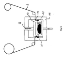
- FIG. 2 shows a vertical sectional view of a closing station 3 according to the invention with the FolienzuGermanrolle 7 and the Restfolienetzwickler 9 for the cover sheet 8.
- a lifting device 12 for a sealing frame 13, to which a knife 14 is mounted, is accommodated in a tool upper part 15.
- the tool lower part 16 has a guide 17 for a tray receptacle 18 with at least one (pressure) spring 19.
- a filled with a product tray 20 with a circumferential and downwardly additionally angled edge is inserted by a handling device, not shown, or manually in the tray receptacle 18 Service.
- a handling device not shown, or manually in the tray receptacle 18 Service.
- Only one shell 20 is shown. In practice, a plurality of successively adjacent and / or adjacent shells are simultaneously closed in a wear station with the cover sheet.
- the lid sheet 8 is clamped circumferentially by the upper die 15 and the lower tool part 16. This area where the lidding film 8 is clamped is defined as a first area. In this position, the upper tool part 15 and the lower tool part 16 form a closed chamber which is evacuated and / or gassed.
- the sealing frame 13 by means of the lifting device 12 in the direction R down and clamps the lid sheet 8 in a second region of the shell 20, which is supported by the shell receptacle 18.
- the clamping force corresponds approximately to the spring force by the springs 19th
- the sealing frame 13 moves toward the tool base 16.
- the tray receptacle 18 moves relative to the tool base 16 down.
- the springs 19 are compressed so far until the tray receptacle 18 abuts the lower tool part 16.
- the shell 20 is moved downwards with the second region of the cover film 8 relative to the tool lower part 16 and also to the upper tool part 15. This leads to a tension in the region of the cover film 8, which is not clamped in a second region by the sealing frame 13 and the shell receptacle 18 or in a first region by the upper tool part 15 and the lower tool part 16.
- the cover sheet 8 comes into contact with the knife 14 and is cut.
- the knife 14 preferably has a serrated shape, which facilitates the cutting process.
- the cover film 8 is, for example, a plastic film or a multilayer film, which may also be shrinkable or skinnable.
- FIG. 6 It is shown that the sealing frame 8 presses further on the shell receptacle 18 in order to produce the sealing force Fs, which is necessary in order to seal the cover film 8 to the shell 20 in the region of the sealing seam 22 airtight.
- FIG. 8 A variant of the arrangement of the blade 14 is in FIG. 8 shown.
- the knife 14 is mounted on the tool lower part 16, wherein the front edge of the knife is very close to the tray receptacle 18 to cut the lid film 8 directly on the outer edge of the package.
- FIG. 9 It is shown how the cover film 8 is cut by the knife 14 by the relative movement R of the sealing frame 13 with the shell receptacle 18 together with the second region of the cover film 8 and the shell 20 with respect to the tool lower part 16.
Claims (12)
- Procédé de coupe d'une pellicule de couvercle (8) dans une station de scellage (3) d'une machine de scellage de coques (1), comprenant les étapes suivantes :serrage de la pellicule de couvercle (8) dans une première zone à l'aide d'une partie d'outil supérieure (15) et d'une partie d'outil inférieure (16) de la station de scellage (3),serrage de la pellicule de couvercle (8) et d'une coque (20) dans une deuxième zone à l'aide d'un châssis de scellage (13) et d'un logement de coque (18),déplacement relatif (R) du châssis de scellage (13) et du logement de coque (18) conjointement avec la deuxième zone de la pellicule de couvercle (8) et la coque (20) par rapport à la partie inférieure de l'outil (16),découpe de la pellicule de couvercle (8) durant le déplacement relatif (R) par contact de la pellicule de couvercle (8) avec au moins un couteau (14), qui est monté sur le châssis de scellage (13) ou sur la partie inférieure de l'outil (16).
- Procédé selon la revendication 1, caractérisé en ce que le déplacement relatif (R) du châssis de scellage (13) et du logement de coque (18) conjointement avec la deuxième zone de la pellicule de couvercle (8) et la coque (20) est effectué en direction de la partie inférieure de l'outil (16).
- Procédé selon l'une des revendications précédentes, caractérisé en ce qu'une zone de la pellicule de couvercle (8) située entre les première et deuxième zones de la pellicule de couvercle (8) est tendue transversalement du fait du déplacement relatif (R).
- Procédé selon l'une des revendications précédentes, caractérisé en ce que le couteau (14) monté sur le châssis de scellage (13) coupe la pellicule de couvercle (8) entre une soudure de scellage (22) et un bord externe de la coque.
- Procédé selon l'une des revendications précédentes, caractérisé en ce que la découpe de la pellicule de couvercle (8) est effectuée avant un scellage de la pellicule de couvercle (8) sur la coque (20).
- Procédé selon l'une des revendications précédentes, caractérisé en ce qu'à la fin du déplacement relatif (R), le châssis de scellage (13) exerce une force de scellage (Fs) sur la pellicule de couvercle (8) et la coque (20) posée sur le logement de coque (18).
- Procédé selon l'une des revendications précédentes, caractérisé en ce qu'avant le scellage, l'intérieur de la coque (20) est mis sous vide et/ou purgé avec un gaz.
- Station de scellage (3) pour machine de scellage de coques (1), dans laquelle la station de scellage (3) comporte une partie d'outil supérieure (15) et une partie d'outil inférieure (16) pour serrer une première zone d'une pellicule de couvercle (8), un logement de coque (18) et un châssis de scellage (13) pour serrer une deuxième zone de la pellicule de couvercle (8) sur une coque (20), ainsi qu'un couteau (14) pourvu pour couper la pellicule de couvercle (8) et monté sur le châssis de scellage (13) ou sur la partie inférieure de l'outil (16), dans laquelle la station de scellage (3) comporte en outre un dispositif de levage (12) pour le châssis de scellage (13), caractérisée en ce que le châssis de scellage (13) et le logement de coque (18) peuvent être déplacés conjointement avec la deuxième zone de la pellicule de couvercle (8) et la coque (20) par rapport à la partie inférieure de l'outil (16).
- Station de scellage selon la revendication 8, caractérisée en ce que la distance latérale entre le couteau (14) et le châssis de scellage (13) est inférieure à 6 mm, et préférablement inférieure à 3 mm.
- Station de scellage selon la revendication 8 ou 9, caractérisée en ce que le couteau (14) présente une forme annulaire.
- Station de scellage selon l'une des revendications 8 à 10, caractérisée en ce que le dispositif de levage (12) est constitué de telle sorte que, dans une position où le logement de coque (18) est en contact avec la partie inférieure de l'outil (16), une force de scellage (Fs) du châssis de scellage (13) s'exerce sur la pellicule de couvercle (8) et la coque (20).
- Machine d'emballage comportant une station de scellage selon l'une des revendications 8 à 11.
Priority Applications (3)
| Application Number | Priority Date | Filing Date | Title |
|---|---|---|---|
| ES10013569T ES2397939T3 (es) | 2010-10-12 | 2010-10-12 | Estación de cierre y procedimiento para cortar una lámina de tapa |
| EP20100013569 EP2441683B1 (fr) | 2010-10-12 | 2010-10-12 | Station de verrouillage et procédé de coupe d'une pellicule de couvercle |
| US13/270,480 US9073656B2 (en) | 2010-10-12 | 2011-10-11 | Sealing station and method for cutting a cover film |
Applications Claiming Priority (1)
| Application Number | Priority Date | Filing Date | Title |
|---|---|---|---|
| EP20100013569 EP2441683B1 (fr) | 2010-10-12 | 2010-10-12 | Station de verrouillage et procédé de coupe d'une pellicule de couvercle |
Publications (2)
| Publication Number | Publication Date |
|---|---|
| EP2441683A1 EP2441683A1 (fr) | 2012-04-18 |
| EP2441683B1 true EP2441683B1 (fr) | 2012-12-12 |
Family
ID=43640062
Family Applications (1)
| Application Number | Title | Priority Date | Filing Date |
|---|---|---|---|
| EP20100013569 Active EP2441683B1 (fr) | 2010-10-12 | 2010-10-12 | Station de verrouillage et procédé de coupe d'une pellicule de couvercle |
Country Status (3)
| Country | Link |
|---|---|
| US (1) | US9073656B2 (fr) |
| EP (1) | EP2441683B1 (fr) |
| ES (1) | ES2397939T3 (fr) |
Cited By (1)
| Publication number | Priority date | Publication date | Assignee | Title |
|---|---|---|---|---|
| EP3450327A1 (fr) | 2017-08-30 | 2019-03-06 | MULTIVAC Sepp Haggenmüller SE & Co. KG | Station de soudage ainsi que procédé de fabrication d'emballage blister pourvu d'un angle d'arrachage |
Families Citing this family (13)
| Publication number | Priority date | Publication date | Assignee | Title |
|---|---|---|---|---|
| IT1403023B1 (it) * | 2010-12-13 | 2013-09-27 | Blu Pack Di Scolaro Mauro | Dispositivo per il confezionamento sottovuoto, particolarmente di prodotti alimentari |
| DE102012012481A1 (de) * | 2012-06-22 | 2013-12-24 | Multivac Sepp Haggenmüller Gmbh & Co. Kg | Siegelvorrichtung einer Schalenverschließmaschine |
| CN102862708B (zh) * | 2012-09-24 | 2014-08-20 | 金晖(中山)金属制造有限公司 | 一种试剂自动封口机 |
| CN104354930B (zh) * | 2014-09-18 | 2016-06-15 | 中北大学 | 自动蔬菜包装机同步包封系统 |
| ES2848175T3 (es) | 2015-08-31 | 2021-08-05 | Converter Mfg Llc | Artículo termoplástico conformado con bordes lisos |
| DE102016123569A1 (de) | 2016-12-06 | 2018-06-07 | Multivac Sepp Haggenmüller Se & Co. Kg | Schalenverschließmaschine |
| CN108657529A (zh) * | 2018-06-06 | 2018-10-16 | 江苏盖之宝包装科技有限公司 | 一种热成型包装机的封合装置 |
| CN110092021B (zh) * | 2019-06-14 | 2024-02-09 | 北海绩迅科技股份有限公司 | 自动墨盒封口装置 |
| CN112937977B (zh) * | 2020-05-26 | 2023-04-28 | 内蒙古快为科技有限公司 | 基于曲柄摇杆机构的蔬菜封膜装置 |
| US20230264889A1 (en) * | 2020-06-26 | 2023-08-24 | Wenco S.A. | Container with sealable body for packaging and transporting fruit and vegetable produce and method for applying a sealing film to the container |
| GB2598347A (en) * | 2020-08-27 | 2022-03-02 | Ishida Europe Ltd | System and method for sealing containers |
| DE102020129551A1 (de) * | 2020-11-10 | 2022-05-12 | Multivac Sepp Haggenmüller Se & Co. Kg | Formstation zum Ausformen von Verpackungsmulden |
| CN112319885B (zh) * | 2020-12-01 | 2022-05-17 | 广东顶鑫农业供应链集团有限公司 | 一种食品保鲜膜包装引导覆盖装置 |
Family Cites Families (31)
| Publication number | Priority date | Publication date | Assignee | Title |
|---|---|---|---|---|
| FR1379203A (fr) * | 1962-12-18 | 1964-11-20 | Bellmann & Co | Perfectionnements apportés aux procédés pour conserver et sceller les récipientsen matière thermoplastique contenant des aliments apprêtés et aux installations pour la mise en oeuvre de ces procédés |
| GB1206667A (en) * | 1968-05-15 | 1970-09-30 | Sidaplax S A | Production of packages |
| NZ195962A (en) * | 1980-01-16 | 1984-11-09 | Metal Box Co Ltd | Vacuum packing a product in a rigid container so as to leave no headspace |
| US4707213A (en) * | 1985-11-12 | 1987-11-17 | Continental Can Company, Inc. | Induction heating unit for heat bonding a lid having a metallic layer to a container |
| GB8729725D0 (en) * | 1987-12-21 | 1988-02-03 | Metal Box Plc | Container with peelable seal & method & apparatus for making same |
| US5534282A (en) * | 1989-08-30 | 1996-07-09 | Seawell North America Inc. | Packing perishable goods |
| US5056296A (en) * | 1990-03-30 | 1991-10-15 | R. J. R. Polymers, Inc. | Iso-thermal seal process for electronic devices |
| US5348752A (en) * | 1993-05-20 | 1994-09-20 | World Class Packaging Systems, Inc. | Dual state food packaging |
| US6305149B1 (en) * | 1993-11-18 | 2001-10-23 | Marlen Research Corporation | Method and apparatus for packaging meat |
| US5718101A (en) * | 1996-06-04 | 1998-02-17 | W. R. Grace & Co.-Conn. | Method and apparatus for packaging a product in a dual-lid package |
| JP3233643B2 (ja) * | 1996-07-08 | 2001-11-26 | クライオバツク・インコーポレイテッド | 気密密閉包装およびその製造方法と製造機 |
| US6351928B2 (en) * | 1996-12-17 | 2002-03-05 | Minipack Torre S.P.A. | Device for packaging products in containers sealed with stretchable plastic film |
| US5779050A (en) * | 1997-03-11 | 1998-07-14 | W. R. Grace & Co.-Conn. | Lidded package having a tab to facilitate peeling |
| DE69804649T2 (de) * | 1997-10-06 | 2003-02-13 | Rossi Jean Pierre | Vorrichtung zum konditionieren in einer kontrollierten atmosphäre von produkten in mit einer folie versiegelten behältern |
| FR2775253B1 (fr) * | 1998-02-23 | 2000-05-26 | Aprilis | Procede et installation pour la fabrication d'emballages destines notamment a la presentation et la conservation de produits alimentaires |
| US5913860A (en) | 1998-02-27 | 1999-06-22 | Synthes (Usa) | Surgical nail inserter |
| US6050055A (en) * | 1998-08-21 | 2000-04-18 | Westvaco Corporation | Apparatus and method for sealing of paperboard containers using induction heated metal bands |
| DE10031356B4 (de) * | 2000-06-28 | 2004-07-29 | A.L.X.-Metall, Verpackungstechnik, Dipl.-Ing. Alexander Josek GmbH | Vorrichtung zum Verschließen eines Gegenstandes mittels einer heißsiegelbaren Verpackungsbahn |
| US20030196412A1 (en) * | 2002-04-19 | 2003-10-23 | Foulke Guy L. | Top formed packaging |
| DE10237933A1 (de) * | 2002-08-14 | 2004-02-26 | Multivac Sepp Haggenmüller Gmbh & Co. Kg | Verfahren und Verpackungsmaschine zum Verpacken eines in einer Schale befindlichen Produktes |
| EP1400463A1 (fr) * | 2002-09-20 | 2004-03-24 | CFS Palazzolo S.p.A. | Récipient d'emballage à bords scéllés, machine d'emballage et procédé de scellement de cet emballage |
| US6834476B2 (en) * | 2002-10-17 | 2004-12-28 | Ibaraki Seiki Machinery Company, Ltd. | Sealing and packaging device for cover film on tray |
| JP4339765B2 (ja) * | 2004-09-07 | 2009-10-07 | 茨木精機株式会社 | トレイに対するカバーフイルムのシール包装装置 |
| JP2006168736A (ja) * | 2004-12-13 | 2006-06-29 | Ibaraki Precision Mach Co Ltd | トレイにカバーフイルムを被せシールする包装装置 |
| US7665281B2 (en) * | 2005-07-13 | 2010-02-23 | Cfs Germany Gmbh | Machine for making packaging with form-fit connection |
| DE102009020898B4 (de) * | 2009-05-13 | 2014-05-28 | Multivac Sepp Haggenmüller Gmbh & Co. Kg | Tiefziehverpackungsmaschine für mehrlagige Deckelfolie |
| DE102009020892A1 (de) * | 2009-05-13 | 2011-02-10 | Multivac Sepp Haggenmüller Gmbh & Co. Kg | Verpackungsmaschine und Verfahren zum Verschließen von Behältern mit Deckeln |
| DE102009049179B4 (de) * | 2009-10-13 | 2023-10-12 | Multivac Sepp Haggenmüller Se & Co. Kg | Verfahren und Verpackungsmaschine zum Verpacken von Produkten |
| DE102010004635B4 (de) * | 2010-01-14 | 2011-09-22 | Multivac Sepp Haggenmüller Gmbh & Co. Kg | Siegelwerkzeug |
| DE102011105513A1 (de) * | 2011-06-24 | 2012-12-27 | Multivac Sepp Haggenmüller Gmbh & Co. Kg | Verfahren und Siegelstation zum Versiegeln von Verpackungen |
| DE102011110407B3 (de) * | 2011-08-12 | 2013-01-17 | Multivac Sepp Haggenmüller Gmbh & Co. Kg | Siegelstation und Verfahren für deren Betrieb |
-
2010
- 2010-10-12 EP EP20100013569 patent/EP2441683B1/fr active Active
- 2010-10-12 ES ES10013569T patent/ES2397939T3/es active Active
-
2011
- 2011-10-11 US US13/270,480 patent/US9073656B2/en active Active
Cited By (1)
| Publication number | Priority date | Publication date | Assignee | Title |
|---|---|---|---|---|
| EP3450327A1 (fr) | 2017-08-30 | 2019-03-06 | MULTIVAC Sepp Haggenmüller SE & Co. KG | Station de soudage ainsi que procédé de fabrication d'emballage blister pourvu d'un angle d'arrachage |
Also Published As
| Publication number | Publication date |
|---|---|
| EP2441683A1 (fr) | 2012-04-18 |
| ES2397939T3 (es) | 2013-03-12 |
| US9073656B2 (en) | 2015-07-07 |
| US20120085069A1 (en) | 2012-04-12 |
Similar Documents
| Publication | Publication Date | Title |
|---|---|---|
| EP2441683B1 (fr) | Station de verrouillage et procédé de coupe d'une pellicule de couvercle | |
| EP2251264B1 (fr) | Machine d'emballage et procédé de fermeture de récipients dotés de couvercles | |
| EP1521706B1 (fr) | Procede et machine d'emballage pour emballer un produit situe dans une barquette | |
| EP1984250B1 (fr) | Machine d'emballage pour la preparation d'un emballage avec retrait dans le bord de la barquette d'emballage | |
| EP0398306B1 (fr) | Machine à chambre à vide | |
| EP2537761B1 (fr) | Procédé et poste de scellage pour le scellement d'emballages | |
| EP2769923B1 (fr) | Machine d'emballage par emboutissage profond avec poste de scellage et procédé | |
| EP2644516B1 (fr) | Machine d'emballage dotée d'une scelleuse | |
| DE1561956A1 (de) | Verfahren und Vorrichtung zum Verpacken in einer Schutzatmosphaere | |
| EP3450327B1 (fr) | Station de soudage ainsi que procédé de fabrication d'emballage blister pourvu d'un angle d'arrachage | |
| EP2004491A1 (fr) | Procédé de fabrication d'un emballage et machine à emballer | |
| EP2551203A1 (fr) | Procédé destiné à couper des emballages | |
| WO1994016949A1 (fr) | Procede et dispositif permettant de remplir et de fermer un emballage | |
| EP2412632B1 (fr) | Machine d'emballage par emboutissage et procédé de remplissage de barquettes d'emballage avec des produits | |
| DE102012001817A1 (de) | Verpackungsmaschine | |
| DE19604608C1 (de) | Schneideeinrichtung zum Zerkleinern von leeren Bauteilegurten | |
| EP1747880B1 (fr) | Dispositif et méthode pour appliquer une paroi à un conteneur | |
| DE19820408C2 (de) | Vorrichtung zum Ausstanzen von Behältern aus einer Folienbahn | |
| EP2468633B1 (fr) | Machine de fermeture de barquettes et procédé de fonctionnement d'une telle machine de fermeture | |
| EP3539883B1 (fr) | Machine d'emballage par emboutissage à renversement de feuille | |
| EP1575831B1 (fr) | Dispositif et procede d'emballage de bouteilles, notamment de lots de bouteilles | |
| EP2783990A1 (fr) | Machine de verrouillage de coques et procédé | |
| EP2995441B1 (fr) | Machine d'emballage par emboutissage avec dispositif de levage et procédé | |
| EP3880559A2 (fr) | Emballage double à chargement de gaz de protection différent | |
| DE102008026450A1 (de) | Verfahren und Vorrichtung zur Herstellung von Zuschnitten für Zigarettenpackungen |
Legal Events
| Date | Code | Title | Description |
|---|---|---|---|
| PUAI | Public reference made under article 153(3) epc to a published international application that has entered the european phase |
Free format text: ORIGINAL CODE: 0009012 |
|
| AK | Designated contracting states |
Kind code of ref document: A1 Designated state(s): AL AT BE BG CH CY CZ DE DK EE ES FI FR GB GR HR HU IE IS IT LI LT LU LV MC MK MT NL NO PL PT RO RS SE SI SK SM TR |
|
| AX | Request for extension of the european patent |
Extension state: BA ME |
|
| 17P | Request for examination filed |
Effective date: 20120518 |
|
| GRAP | Despatch of communication of intention to grant a patent |
Free format text: ORIGINAL CODE: EPIDOSNIGR1 |
|
| GRAS | Grant fee paid |
Free format text: ORIGINAL CODE: EPIDOSNIGR3 |
|
| GRAA | (expected) grant |
Free format text: ORIGINAL CODE: 0009210 |
|
| AK | Designated contracting states |
Kind code of ref document: B1 Designated state(s): AL AT BE BG CH CY CZ DE DK EE ES FI FR GB GR HR HU IE IS IT LI LT LU LV MC MK MT NL NO PL PT RO RS SE SI SK SM TR |
|
| REG | Reference to a national code |
Ref country code: GB Ref legal event code: FG4D Free format text: NOT ENGLISH |
|
| REG | Reference to a national code |
Ref country code: CH Ref legal event code: NV Representative=s name: BOVARD AG, CH Ref country code: CH Ref legal event code: EP |
|
| REG | Reference to a national code |
Ref country code: AT Ref legal event code: REF Ref document number: 588199 Country of ref document: AT Kind code of ref document: T Effective date: 20121215 |
|
| REG | Reference to a national code |
Ref country code: IE Ref legal event code: FG4D Free format text: LANGUAGE OF EP DOCUMENT: GERMAN |
|
| REG | Reference to a national code |
Ref country code: DE Ref legal event code: R096 Ref document number: 502010001837 Country of ref document: DE Effective date: 20130207 |
|
| REG | Reference to a national code |
Ref country code: ES Ref legal event code: FG2A Ref document number: 2397939 Country of ref document: ES Kind code of ref document: T3 Effective date: 20130312 |
|
| PG25 | Lapsed in a contracting state [announced via postgrant information from national office to epo] |
Ref country code: SE Free format text: LAPSE BECAUSE OF FAILURE TO SUBMIT A TRANSLATION OF THE DESCRIPTION OR TO PAY THE FEE WITHIN THE PRESCRIBED TIME-LIMIT Effective date: 20121212 Ref country code: NO Free format text: LAPSE BECAUSE OF FAILURE TO SUBMIT A TRANSLATION OF THE DESCRIPTION OR TO PAY THE FEE WITHIN THE PRESCRIBED TIME-LIMIT Effective date: 20130312 Ref country code: HR Free format text: LAPSE BECAUSE OF FAILURE TO SUBMIT A TRANSLATION OF THE DESCRIPTION OR TO PAY THE FEE WITHIN THE PRESCRIBED TIME-LIMIT Effective date: 20121212 Ref country code: FI Free format text: LAPSE BECAUSE OF FAILURE TO SUBMIT A TRANSLATION OF THE DESCRIPTION OR TO PAY THE FEE WITHIN THE PRESCRIBED TIME-LIMIT Effective date: 20121212 Ref country code: LT Free format text: LAPSE BECAUSE OF FAILURE TO SUBMIT A TRANSLATION OF THE DESCRIPTION OR TO PAY THE FEE WITHIN THE PRESCRIBED TIME-LIMIT Effective date: 20121212 |
|
| REG | Reference to a national code |
Ref country code: NL Ref legal event code: VDEP Effective date: 20121212 |
|
| REG | Reference to a national code |
Ref country code: LT Ref legal event code: MG4D |
|
| PG25 | Lapsed in a contracting state [announced via postgrant information from national office to epo] |
Ref country code: GR Free format text: LAPSE BECAUSE OF FAILURE TO SUBMIT A TRANSLATION OF THE DESCRIPTION OR TO PAY THE FEE WITHIN THE PRESCRIBED TIME-LIMIT Effective date: 20130313 Ref country code: SI Free format text: LAPSE BECAUSE OF FAILURE TO SUBMIT A TRANSLATION OF THE DESCRIPTION OR TO PAY THE FEE WITHIN THE PRESCRIBED TIME-LIMIT Effective date: 20121212 Ref country code: LV Free format text: LAPSE BECAUSE OF FAILURE TO SUBMIT A TRANSLATION OF THE DESCRIPTION OR TO PAY THE FEE WITHIN THE PRESCRIBED TIME-LIMIT Effective date: 20121212 |
|
| PG25 | Lapsed in a contracting state [announced via postgrant information from national office to epo] |
Ref country code: RS Free format text: LAPSE BECAUSE OF FAILURE TO SUBMIT A TRANSLATION OF THE DESCRIPTION OR TO PAY THE FEE WITHIN THE PRESCRIBED TIME-LIMIT Effective date: 20121212 Ref country code: CZ Free format text: LAPSE BECAUSE OF FAILURE TO SUBMIT A TRANSLATION OF THE DESCRIPTION OR TO PAY THE FEE WITHIN THE PRESCRIBED TIME-LIMIT Effective date: 20121212 Ref country code: EE Free format text: LAPSE BECAUSE OF FAILURE TO SUBMIT A TRANSLATION OF THE DESCRIPTION OR TO PAY THE FEE WITHIN THE PRESCRIBED TIME-LIMIT Effective date: 20121212 Ref country code: IS Free format text: LAPSE BECAUSE OF FAILURE TO SUBMIT A TRANSLATION OF THE DESCRIPTION OR TO PAY THE FEE WITHIN THE PRESCRIBED TIME-LIMIT Effective date: 20130412 Ref country code: BG Free format text: LAPSE BECAUSE OF FAILURE TO SUBMIT A TRANSLATION OF THE DESCRIPTION OR TO PAY THE FEE WITHIN THE PRESCRIBED TIME-LIMIT Effective date: 20130312 Ref country code: SK Free format text: LAPSE BECAUSE OF FAILURE TO SUBMIT A TRANSLATION OF THE DESCRIPTION OR TO PAY THE FEE WITHIN THE PRESCRIBED TIME-LIMIT Effective date: 20121212 |
|
| PG25 | Lapsed in a contracting state [announced via postgrant information from national office to epo] |
Ref country code: NL Free format text: LAPSE BECAUSE OF FAILURE TO SUBMIT A TRANSLATION OF THE DESCRIPTION OR TO PAY THE FEE WITHIN THE PRESCRIBED TIME-LIMIT Effective date: 20121212 Ref country code: PT Free format text: LAPSE BECAUSE OF FAILURE TO SUBMIT A TRANSLATION OF THE DESCRIPTION OR TO PAY THE FEE WITHIN THE PRESCRIBED TIME-LIMIT Effective date: 20130412 Ref country code: RO Free format text: LAPSE BECAUSE OF FAILURE TO SUBMIT A TRANSLATION OF THE DESCRIPTION OR TO PAY THE FEE WITHIN THE PRESCRIBED TIME-LIMIT Effective date: 20121212 Ref country code: PL Free format text: LAPSE BECAUSE OF FAILURE TO SUBMIT A TRANSLATION OF THE DESCRIPTION OR TO PAY THE FEE WITHIN THE PRESCRIBED TIME-LIMIT Effective date: 20121212 |
|
| PLBE | No opposition filed within time limit |
Free format text: ORIGINAL CODE: 0009261 |
|
| STAA | Information on the status of an ep patent application or granted ep patent |
Free format text: STATUS: NO OPPOSITION FILED WITHIN TIME LIMIT |
|
| PG25 | Lapsed in a contracting state [announced via postgrant information from national office to epo] |
Ref country code: DK Free format text: LAPSE BECAUSE OF FAILURE TO SUBMIT A TRANSLATION OF THE DESCRIPTION OR TO PAY THE FEE WITHIN THE PRESCRIBED TIME-LIMIT Effective date: 20121212 |
|
| 26N | No opposition filed |
Effective date: 20130913 |
|
| PG25 | Lapsed in a contracting state [announced via postgrant information from national office to epo] |
Ref country code: CY Free format text: LAPSE BECAUSE OF FAILURE TO SUBMIT A TRANSLATION OF THE DESCRIPTION OR TO PAY THE FEE WITHIN THE PRESCRIBED TIME-LIMIT Effective date: 20121212 |
|
| REG | Reference to a national code |
Ref country code: DE Ref legal event code: R097 Ref document number: 502010001837 Country of ref document: DE Effective date: 20130913 |
|
| BERE | Be: lapsed |
Owner name: MULTIVAC SEPP HAGGENMULLER G.M.B.H. & CO KG Effective date: 20131031 |
|
| PG25 | Lapsed in a contracting state [announced via postgrant information from national office to epo] |
Ref country code: MC Free format text: LAPSE BECAUSE OF FAILURE TO SUBMIT A TRANSLATION OF THE DESCRIPTION OR TO PAY THE FEE WITHIN THE PRESCRIBED TIME-LIMIT Effective date: 20121212 |
|
| REG | Reference to a national code |
Ref country code: IE Ref legal event code: MM4A |
|
| PG25 | Lapsed in a contracting state [announced via postgrant information from national office to epo] |
Ref country code: BE Free format text: LAPSE BECAUSE OF NON-PAYMENT OF DUE FEES Effective date: 20131031 |
|
| PG25 | Lapsed in a contracting state [announced via postgrant information from national office to epo] |
Ref country code: IE Free format text: LAPSE BECAUSE OF NON-PAYMENT OF DUE FEES Effective date: 20131012 |
|
| PG25 | Lapsed in a contracting state [announced via postgrant information from national office to epo] |
Ref country code: SM Free format text: LAPSE BECAUSE OF FAILURE TO SUBMIT A TRANSLATION OF THE DESCRIPTION OR TO PAY THE FEE WITHIN THE PRESCRIBED TIME-LIMIT Effective date: 20121212 |
|
| PG25 | Lapsed in a contracting state [announced via postgrant information from national office to epo] |
Ref country code: MK Free format text: LAPSE BECAUSE OF FAILURE TO SUBMIT A TRANSLATION OF THE DESCRIPTION OR TO PAY THE FEE WITHIN THE PRESCRIBED TIME-LIMIT Effective date: 20121212 Ref country code: LU Free format text: LAPSE BECAUSE OF NON-PAYMENT OF DUE FEES Effective date: 20131012 Ref country code: HU Free format text: LAPSE BECAUSE OF FAILURE TO SUBMIT A TRANSLATION OF THE DESCRIPTION OR TO PAY THE FEE WITHIN THE PRESCRIBED TIME-LIMIT; INVALID AB INITIO Effective date: 20101012 |
|
| PG25 | Lapsed in a contracting state [announced via postgrant information from national office to epo] |
Ref country code: MT Free format text: LAPSE BECAUSE OF FAILURE TO SUBMIT A TRANSLATION OF THE DESCRIPTION OR TO PAY THE FEE WITHIN THE PRESCRIBED TIME-LIMIT Effective date: 20121212 |
|
| REG | Reference to a national code |
Ref country code: FR Ref legal event code: PLFP Year of fee payment: 6 |
|
| REG | Reference to a national code |
Ref country code: DE Ref legal event code: R082 Ref document number: 502010001837 Country of ref document: DE Representative=s name: GRUENECKER PATENT- UND RECHTSANWAELTE PARTG MB, DE Ref country code: DE Ref legal event code: R081 Ref document number: 502010001837 Country of ref document: DE Owner name: MULTIVAC SEPP HAGGENMUELLER SE & CO. KG, DE Free format text: FORMER OWNER: MULTIVAC SEPP HAGGENMUELLER GMBH & CO. KG, 87787 WOLFERTSCHWENDEN, DE |
|
| REG | Reference to a national code |
Ref country code: FR Ref legal event code: PLFP Year of fee payment: 7 |
|
| REG | Reference to a national code |
Ref country code: AT Ref legal event code: MM01 Ref document number: 588199 Country of ref document: AT Kind code of ref document: T Effective date: 20151012 |
|
| PG25 | Lapsed in a contracting state [announced via postgrant information from national office to epo] |
Ref country code: AT Free format text: LAPSE BECAUSE OF NON-PAYMENT OF DUE FEES Effective date: 20151012 |
|
| REG | Reference to a national code |
Ref country code: FR Ref legal event code: PLFP Year of fee payment: 8 |
|
| REG | Reference to a national code |
Ref country code: FR Ref legal event code: PLFP Year of fee payment: 9 |
|
| PG25 | Lapsed in a contracting state [announced via postgrant information from national office to epo] |
Ref country code: AL Free format text: LAPSE BECAUSE OF FAILURE TO SUBMIT A TRANSLATION OF THE DESCRIPTION OR TO PAY THE FEE WITHIN THE PRESCRIBED TIME-LIMIT Effective date: 20121212 |
|
| P01 | Opt-out of the competence of the unified patent court (upc) registered |
Effective date: 20230404 |
|
| PGFP | Annual fee paid to national office [announced via postgrant information from national office to epo] |
Ref country code: GB Payment date: 20231025 Year of fee payment: 14 |
|
| PGFP | Annual fee paid to national office [announced via postgrant information from national office to epo] |
Ref country code: ES Payment date: 20231117 Year of fee payment: 14 |
|
| PGFP | Annual fee paid to national office [announced via postgrant information from national office to epo] |
Ref country code: TR Payment date: 20231004 Year of fee payment: 14 Ref country code: IT Payment date: 20231031 Year of fee payment: 14 Ref country code: FR Payment date: 20231023 Year of fee payment: 14 Ref country code: DE Payment date: 20231018 Year of fee payment: 14 Ref country code: CH Payment date: 20231102 Year of fee payment: 14 |