EP2441602A1 - Suspension de roue avec une jambe de ressort-amortisseur - Google Patents
Suspension de roue avec une jambe de ressort-amortisseur Download PDFInfo
- Publication number
- EP2441602A1 EP2441602A1 EP10186998A EP10186998A EP2441602A1 EP 2441602 A1 EP2441602 A1 EP 2441602A1 EP 10186998 A EP10186998 A EP 10186998A EP 10186998 A EP10186998 A EP 10186998A EP 2441602 A1 EP2441602 A1 EP 2441602A1
- Authority
- EP
- European Patent Office
- Prior art keywords
- spring
- damper strut
- suspension
- damper
- steering
- Prior art date
- Legal status (The legal status is an assumption and is not a legal conclusion. Google has not performed a legal analysis and makes no representation as to the accuracy of the status listed.)
- Withdrawn
Links
Images

Classifications
-
- B—PERFORMING OPERATIONS; TRANSPORTING
- B60—VEHICLES IN GENERAL
- B60G—VEHICLE SUSPENSION ARRANGEMENTS
- B60G15/00—Resilient suspensions characterised by arrangement, location or type of combined spring and vibration damper, e.g. telescopic type
- B60G15/02—Resilient suspensions characterised by arrangement, location or type of combined spring and vibration damper, e.g. telescopic type having mechanical spring
- B60G15/06—Resilient suspensions characterised by arrangement, location or type of combined spring and vibration damper, e.g. telescopic type having mechanical spring and fluid damper
- B60G15/062—Resilient suspensions characterised by arrangement, location or type of combined spring and vibration damper, e.g. telescopic type having mechanical spring and fluid damper the spring being arranged around the damper
-
- B—PERFORMING OPERATIONS; TRANSPORTING
- B60—VEHICLES IN GENERAL
- B60G—VEHICLE SUSPENSION ARRANGEMENTS
- B60G13/00—Resilient suspensions characterised by arrangement, location or type of vibration dampers
- B60G13/001—Arrangements for attachment of dampers
- B60G13/005—Arrangements for attachment of dampers characterised by the mounting on the axle or suspension arm of the damper unit
- B60G13/006—Arrangements for attachment of dampers characterised by the mounting on the axle or suspension arm of the damper unit on the stub axle
-
- B—PERFORMING OPERATIONS; TRANSPORTING
- B60—VEHICLES IN GENERAL
- B60G—VEHICLE SUSPENSION ARRANGEMENTS
- B60G15/00—Resilient suspensions characterised by arrangement, location or type of combined spring and vibration damper, e.g. telescopic type
- B60G15/02—Resilient suspensions characterised by arrangement, location or type of combined spring and vibration damper, e.g. telescopic type having mechanical spring
- B60G15/06—Resilient suspensions characterised by arrangement, location or type of combined spring and vibration damper, e.g. telescopic type having mechanical spring and fluid damper
- B60G15/07—Resilient suspensions characterised by arrangement, location or type of combined spring and vibration damper, e.g. telescopic type having mechanical spring and fluid damper the damper being connected to the stub axle and the spring being arranged around the damper
-
- B—PERFORMING OPERATIONS; TRANSPORTING
- B60—VEHICLES IN GENERAL
- B60G—VEHICLE SUSPENSION ARRANGEMENTS
- B60G3/00—Resilient suspensions for a single wheel
- B60G3/02—Resilient suspensions for a single wheel with a single pivoted arm
- B60G3/04—Resilient suspensions for a single wheel with a single pivoted arm the arm being essentially transverse to the longitudinal axis of the vehicle
- B60G3/06—Resilient suspensions for a single wheel with a single pivoted arm the arm being essentially transverse to the longitudinal axis of the vehicle the arm being rigid
-
- B—PERFORMING OPERATIONS; TRANSPORTING
- B60—VEHICLES IN GENERAL
- B60G—VEHICLE SUSPENSION ARRANGEMENTS
- B60G2200/00—Indexing codes relating to suspension types
- B60G2200/10—Independent suspensions
- B60G2200/14—Independent suspensions with lateral arms
- B60G2200/142—Independent suspensions with lateral arms with a single lateral arm, e.g. MacPherson type
-
- B—PERFORMING OPERATIONS; TRANSPORTING
- B60—VEHICLES IN GENERAL
- B60G—VEHICLE SUSPENSION ARRANGEMENTS
- B60G2200/00—Indexing codes relating to suspension types
- B60G2200/40—Indexing codes relating to the wheels in the suspensions
- B60G2200/422—Driving wheels or live axles
-
- B—PERFORMING OPERATIONS; TRANSPORTING
- B60—VEHICLES IN GENERAL
- B60G—VEHICLE SUSPENSION ARRANGEMENTS
- B60G2204/00—Indexing codes related to suspensions per se or to auxiliary parts
- B60G2204/10—Mounting of suspension elements
- B60G2204/12—Mounting of springs or dampers
- B60G2204/129—Damper mount on wheel suspension or knuckle
-
- B—PERFORMING OPERATIONS; TRANSPORTING
- B60—VEHICLES IN GENERAL
- B60G—VEHICLE SUSPENSION ARRANGEMENTS
- B60G2206/00—Indexing codes related to the manufacturing of suspensions: constructional features, the materials used, procedures or tools
- B60G2206/01—Constructional features of suspension elements, e.g. arms, dampers, springs
- B60G2206/50—Constructional features of wheel supports or knuckles, e.g. steering knuckles, spindle attachments
Definitions
- the invention relates to a suspension for a motor vehicle referred to in the preamble of claim 1.
- Art Such suspensions of the known McPherson design are used in particular in front suspensions of motor vehicles with front-wheel drive.
- the DE 44 13 412 A1 discloses a bus, wherein such a modular construction is provided that a complete unit of drive unit, gearbox, transfer gear, cardan shaft connection and rear differential is mounted in an assembly carrier.
- the DE 30 05 916 A1 deals with a suspension, in particular a steered motor vehicle front axle, in which the wheel is guided by two superimposed guide arms, in particular transverse or oblique link, and supported by a hinged to the one guide arm damper strut in a mainly vertical direction.
- the shock absorber leg is articulated directly on the lower guide arm, which is articulated on the vehicle body.
- the upper guide arm is hinged to the strut.
- a spring-damper leg is provided, which is connected via two struts with the steering knuckle, wherein the lower of the two struts has above its articulation to the stub axle a second joint which is rotatable about a substantially horizontal axis.
- the disadvantage of this arrangement is that the spring-strut in the side view of the suspension must be perpendicular to the wishbone to avoid jamming in the suspension of the suspension.
- the invention has for its object to develop a suspension that avoids the aforementioned disadvantages and allows a greater reduction in the height of the spring-shock absorber leg support bearing, without losing the benefits of the classic McPherson suspension.
- the object is achieved by a suspension with the features of claim 1, wherein the spring-damper strut in side view of the suspension obliquely to the wishbone, so arranged to the lower arm, while the steering axis through the bearing point of the control arm, so the lower arm on the steering knuckle and the kinematic point of the spring-strut leg support bearing is determined.
- the spring-damper strut is arranged in side view of the suspension obliquely to the control arm, the overall height of the spring-shock absorber leg support bearing can be significantly reduced. This makes it possible to ensure better pedestrian protection and also to adapt the bonnet or the front of the vehicle in terms of the design better and more flexible.
- the angle between the axis of symmetry of the spring-damper strut and the wishbone is not 90 °.
- the realizable angular range does not necessarily result from the kinematics of the suspension and can reach values of up to 30 °.
- the inventive arrangement of the vertical space requirement of the spring-damper strut can be reduced by 10 to 20%, for example, up to 13.4% over the prior art.
- the suspension is designed so that the steering roller radius is negative. This brings the already mentioned advantages with regard to the braking stability.
- the spring-damper strut seen in side view of the suspension is arranged in front of the drive shaft, which also seen in a side view of the suspension arrangement is possible in which the spring-damper strut is arranged behind the drive shaft.
- the spring-damper strut is connected only at one point with the stub axle or with the wheel carrier, wherein the connection or attachment to an upper position of the wheel carrier makes sense. It is also conceivable, however, to provide an additional connection or attachment of the spring-damper strut to the stub axle carrier or wheel carrier, in order to further improve the rigidity and stability, if necessary.
- Fig. 1 shows a first embodiment of the suspension according to the invention in front view.
- the spring-damper strut 10 is fastened to the steering knuckle carrier or wheel carrier 20.
- the stub axle 20 has a bearing point 21 for the transverse link 30. This engages with its end 32 in this bearing 21 a.
- the opposite end 31 of the control arm 30 is pivotally mounted about the axis A2.
- the wheel hub 40 is also provided on the stub axle carrier or wheel carrier 20, the wheel hub 40 is also provided. At this the dashed wheel shown here is attached.
- a tie rod 41 is also included, which is arranged between the stub axle carrier 20 and the steering system of the vehicle and transmits the steering operation via the wheel carrier 20 to the wheels.
- the spring-damper strut 10 forms at the kinematics point of the spring-damper leg support bearing 11 with the bearing 21 together the steering axis A1.
- the spring-damper strut 10 is here in the present embodiment, only at one point or in a mounting region 42 with the Achsschenkelanii or wheel 20 connected. To increase the stability, it may also be expedient to secure the spring-damper strut 10 at its lower end 12 or at its fastening point or region lower to the first fastening region 42 for a second time on the steering knuckle carrier or wheel carrier 20.
- the spring-damper strut 10 is arranged behind the drive shaft 33 as seen in side view (see direction of travel arrow 43). As already mentioned, it is understood obliquely that the angle between the main axis of the spring-damper strut 10 and the transverse link 30 is not 90 °. By this oblique arrangement behind the drive shaft 33, the desired reduction of the height of the spring-damper leg support bearing 11 is made possible here.
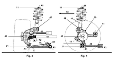
- the 3 and 4 show a further embodiment of a suspension according to the invention.
- the spring-damper strut 10 is here seen in front of the drive shaft 33 arranged (see direction of travel arrow 43). The remaining components remain unchanged.
- the spring-damper strut 10 in turn arranged obliquely to the wishbone 30 in side view of the suspension.
- the spring-damper strut 10 is arranged in front of or behind the drive shaft 33 depends on the particular application. Name, such an arrangement in combination with the inclination of the spring-damper strut 10 to the control arm 30 towards another way of reducing the height of the spring-strut leg support bearing 11, whereby the pedestrian protection improved and the hood can be reduced based on known suspension in height. In addition, much larger wheel movements (seen from the amount of a compression or rebound) can be achieved.
Landscapes
- Engineering & Computer Science (AREA)
- Mechanical Engineering (AREA)
- Vehicle Body Suspensions (AREA)
Priority Applications (2)
| Application Number | Priority Date | Filing Date | Title |
|---|---|---|---|
| EP10186998A EP2441602A1 (fr) | 2010-10-08 | 2010-10-08 | Suspension de roue avec une jambe de ressort-amortisseur |
| CN2011203789938U CN202389141U (zh) | 2010-10-08 | 2011-09-28 | 车轮悬架 |
Applications Claiming Priority (1)
| Application Number | Priority Date | Filing Date | Title |
|---|---|---|---|
| EP10186998A EP2441602A1 (fr) | 2010-10-08 | 2010-10-08 | Suspension de roue avec une jambe de ressort-amortisseur |
Publications (1)
| Publication Number | Publication Date |
|---|---|
| EP2441602A1 true EP2441602A1 (fr) | 2012-04-18 |
Family
ID=43662186
Family Applications (1)
| Application Number | Title | Priority Date | Filing Date |
|---|---|---|---|
| EP10186998A Withdrawn EP2441602A1 (fr) | 2010-10-08 | 2010-10-08 | Suspension de roue avec une jambe de ressort-amortisseur |
Country Status (2)
| Country | Link |
|---|---|
| EP (1) | EP2441602A1 (fr) |
| CN (1) | CN202389141U (fr) |
Cited By (2)
| Publication number | Priority date | Publication date | Assignee | Title |
|---|---|---|---|---|
| DE102013222442A1 (de) | 2013-11-05 | 2015-05-07 | Voith Patent Gmbh | Radaufhängung für ein Kraftfahrzeug |
| DE102013222443A1 (de) | 2013-11-05 | 2015-05-07 | Voith Patent Gmbh | Radaufhängung für ein Kraftfahrzeug |
Families Citing this family (5)
| Publication number | Priority date | Publication date | Assignee | Title |
|---|---|---|---|---|
| CN105015271A (zh) * | 2015-07-23 | 2015-11-04 | 张家港市九鼎机械有限公司 | 一种车辆的前后桥结构及具有该前后桥结构的车辆 |
| CN106541986B (zh) * | 2016-11-08 | 2019-10-01 | 同济大学 | 一种双曲柄传动麦弗逊悬架线控独立转向系统 |
| FR3060465B1 (fr) * | 2016-12-21 | 2019-08-23 | Renault S.A.S | Systeme de suspension et d'amortissement adapte pour le reglage de garde au sol d'un vehicule automobile |
| CN108556580A (zh) * | 2018-02-02 | 2018-09-21 | 福建(泉州)哈工大工程技术研究院 | 一种麦克纳姆轮全向移动平台独立悬架结构 |
| JP2020111270A (ja) * | 2019-01-16 | 2020-07-27 | トヨタ自動車株式会社 | 転舵装置、および、それを備えた車両用車輪配設モジュール |
Citations (11)
| Publication number | Priority date | Publication date | Assignee | Title |
|---|---|---|---|---|
| DE1505549A1 (de) * | 1966-02-23 | 1969-10-30 | Bayerische Motoren Werke Ag | Unabhaengige Aufhaengung der gelenkten Raeder von Kraftfahrzeugen,insbesondere Personenkraftwagen |
| DE2633402A1 (de) * | 1976-07-24 | 1978-01-26 | Opel Adam Ag | Radaufhaengung fuer kraftfahrzeuge, insbesondere personenkraftwagen |
| DE2747561A1 (de) * | 1976-11-26 | 1978-06-01 | Gen Motors Corp | Einzelradaufhaengung fuer kraftfahrzeuge |
| DE2829278A1 (de) * | 1978-07-04 | 1980-01-17 | Volkswagenwerk Ag | Einzelradaufhaengung einer angetriebenen kraftfahrzeug-vorderachse |
| DE2945802A1 (de) | 1978-11-14 | 1980-05-22 | Renault | Vorderradaufhaengung fuer kraftfahrzeuge |
| DE3005916A1 (de) | 1980-02-16 | 1981-09-03 | Daimler-Benz Ag, 7000 Stuttgart | Radaufhaengung, insbesondere einer gelenkten kraftfahrzeug-vorderachse |
| JPH0459404A (ja) * | 1990-06-29 | 1992-02-26 | Nissan Motor Co Ltd | リヤサスペンション装置 |
| DE4413412A1 (de) | 1994-04-18 | 1995-10-19 | Daimler Benz Ag | Omnibus |
| DE19509470A1 (de) * | 1995-03-16 | 1996-09-19 | Porsche Ag | Radaufhängung |
| DE10338045A1 (de) * | 2003-08-19 | 2005-03-10 | Volkswagen Ag | McPherson-Vorderachse für ein Kraftfahrzeug |
| GB2468302A (en) * | 2009-03-03 | 2010-09-08 | Gordon Murray Design Ltd | Vehicle suspension |
-
2010
- 2010-10-08 EP EP10186998A patent/EP2441602A1/fr not_active Withdrawn
-
2011
- 2011-09-28 CN CN2011203789938U patent/CN202389141U/zh not_active Expired - Fee Related
Patent Citations (12)
| Publication number | Priority date | Publication date | Assignee | Title |
|---|---|---|---|---|
| DE1505549A1 (de) * | 1966-02-23 | 1969-10-30 | Bayerische Motoren Werke Ag | Unabhaengige Aufhaengung der gelenkten Raeder von Kraftfahrzeugen,insbesondere Personenkraftwagen |
| DE2633402A1 (de) * | 1976-07-24 | 1978-01-26 | Opel Adam Ag | Radaufhaengung fuer kraftfahrzeuge, insbesondere personenkraftwagen |
| DE2747561A1 (de) * | 1976-11-26 | 1978-06-01 | Gen Motors Corp | Einzelradaufhaengung fuer kraftfahrzeuge |
| DE2829278A1 (de) * | 1978-07-04 | 1980-01-17 | Volkswagenwerk Ag | Einzelradaufhaengung einer angetriebenen kraftfahrzeug-vorderachse |
| DE2945802A1 (de) | 1978-11-14 | 1980-05-22 | Renault | Vorderradaufhaengung fuer kraftfahrzeuge |
| US4341396A (en) | 1978-11-14 | 1982-07-27 | Regie Nationale Des Usines Renault | Front axle assembly for automobile |
| DE3005916A1 (de) | 1980-02-16 | 1981-09-03 | Daimler-Benz Ag, 7000 Stuttgart | Radaufhaengung, insbesondere einer gelenkten kraftfahrzeug-vorderachse |
| JPH0459404A (ja) * | 1990-06-29 | 1992-02-26 | Nissan Motor Co Ltd | リヤサスペンション装置 |
| DE4413412A1 (de) | 1994-04-18 | 1995-10-19 | Daimler Benz Ag | Omnibus |
| DE19509470A1 (de) * | 1995-03-16 | 1996-09-19 | Porsche Ag | Radaufhängung |
| DE10338045A1 (de) * | 2003-08-19 | 2005-03-10 | Volkswagen Ag | McPherson-Vorderachse für ein Kraftfahrzeug |
| GB2468302A (en) * | 2009-03-03 | 2010-09-08 | Gordon Murray Design Ltd | Vehicle suspension |
Cited By (5)
| Publication number | Priority date | Publication date | Assignee | Title |
|---|---|---|---|---|
| DE102013222442A1 (de) | 2013-11-05 | 2015-05-07 | Voith Patent Gmbh | Radaufhängung für ein Kraftfahrzeug |
| DE102013222443A1 (de) | 2013-11-05 | 2015-05-07 | Voith Patent Gmbh | Radaufhängung für ein Kraftfahrzeug |
| WO2015067638A2 (fr) | 2013-11-05 | 2015-05-14 | Voith Patent Gmbh | Suspension de roue pour véhicule automobile |
| DE102013222442B4 (de) * | 2013-11-05 | 2016-12-15 | Brist Axle Systems S.R.L. | Radaufhängung für ein lenkbares Antriebsrad bei einem Kraftfahrzeug |
| US10124639B2 (en) | 2013-11-05 | 2018-11-13 | Brist Axle Systems S.R.L. | Wheel suspension for a motor vehicle |
Also Published As
| Publication number | Publication date |
|---|---|
| CN202389141U (zh) | 2012-08-22 |
Similar Documents
| Publication | Publication Date | Title |
|---|---|---|
| DE102016220786B4 (de) | Hinterradaufhängung für Kraftfahrzeuge | |
| EP2441602A1 (fr) | Suspension de roue avec une jambe de ressort-amortisseur | |
| DE4313978A1 (de) | Aufhaengungseinrichtung fuer ein gelenktes rad | |
| DE102006016762A1 (de) | Achsschenkel für ein Fahrzeug | |
| DE102012011865A1 (de) | Radaufhängung | |
| DE102013216029B4 (de) | Lenkbare Vorderachse für Räder eines zweispurigen Kraftfahrzeugs und zweispuriges Kraftfahrzeug mit einer solchen Vorderachse | |
| DE102011018276A1 (de) | Radaufhängung für eine Achse eines Kraftfahrzeuges | |
| WO2014124721A1 (fr) | Suspension de roue conçue pour un véhicule automobile | |
| DE102012011868A1 (de) | Radaufhängung | |
| DE102015201338A1 (de) | Schräglenkerachse zur Aufhängung eines Kraftfahrzeugrades | |
| EP1346854B1 (fr) | Suspension de roue de véhicule automobile | |
| DE102015212580A1 (de) | Radaufhängungsanordnung | |
| DE102015206443A1 (de) | Radaufhängung für ein Fahrzeug | |
| DE60306730T2 (de) | Lenkeinrichtung für die Trage-Einrichtung der Hinterradnabe in Motorfahrzeugen | |
| DE202017100164U1 (de) | Hinterradaufhängung für Kraftfahrzeuge | |
| WO2014012636A1 (fr) | Suspension de roue pour le pont arrière d'un véhicule | |
| DE102018207616B4 (de) | Radaufhängung für ein Kraftfahrzeug | |
| DE102012011864A1 (de) | Radaufhängung | |
| DE102011006555A1 (de) | Radaufhängung für Fahrzeuge | |
| EP1738938A2 (fr) | Suspension arrière de roue indépendante multi bras | |
| DE202015101117U1 (de) | Einzelradaufhängung sowie Hinterachse mit Einzelradaufhängungen für ein Fahrzeug | |
| DE102019200214A1 (de) | Lenkbare Verbundlenkerachse für ein Kraftfahrzeug, Längslenker und Kraftfahrzeug | |
| DE102008029337A1 (de) | Achsaufhängung für einen Achskörper eines Fahrzeugs | |
| DE102012221699A1 (de) | Radaufhängung für ein Fahrzeug mit aktiver Radsturzverstellung | |
| DE10249445A1 (de) | Lenker mit Schwenkarm |
Legal Events
| Date | Code | Title | Description |
|---|---|---|---|
| PUAI | Public reference made under article 153(3) epc to a published international application that has entered the european phase |
Free format text: ORIGINAL CODE: 0009012 |
|
| AK | Designated contracting states |
Kind code of ref document: A1 Designated state(s): AL AT BE BG CH CY CZ DE DK EE ES FI FR GB GR HR HU IE IS IT LI LT LU LV MC MK MT NL NO PL PT RO RS SE SI SK SM TR |
|
| AX | Request for extension of the european patent |
Extension state: BA ME |
|
| STAA | Information on the status of an ep patent application or granted ep patent |
Free format text: STATUS: THE APPLICATION HAS BEEN WITHDRAWN |
|
| 18W | Application withdrawn |
Effective date: 20120503 |