EP2440458B1 - Schnittstellensystem zur verwendung in einer flugzeugbordküche und verfahren - Google Patents
Schnittstellensystem zur verwendung in einer flugzeugbordküche und verfahren Download PDFInfo
- Publication number
- EP2440458B1 EP2440458B1 EP10725031.8A EP10725031A EP2440458B1 EP 2440458 B1 EP2440458 B1 EP 2440458B1 EP 10725031 A EP10725031 A EP 10725031A EP 2440458 B1 EP2440458 B1 EP 2440458B1
- Authority
- EP
- European Patent Office
- Prior art keywords
- galley
- connection
- appliance
- compartment
- connection element
- Prior art date
- Legal status (The legal status is an assumption and is not a legal conclusion. Google has not performed a legal analysis and makes no representation as to the accuracy of the status listed.)
- Not-in-force
Links
- 238000000034 method Methods 0.000 title claims description 8
- 239000013505 freshwater Substances 0.000 claims description 70
- 239000002351 wastewater Substances 0.000 claims description 54
- 230000000295 complement effect Effects 0.000 claims description 14
- 125000006850 spacer group Chemical group 0.000 claims description 5
- XLYOFNOQVPJJNP-UHFFFAOYSA-N water Substances O XLYOFNOQVPJJNP-UHFFFAOYSA-N 0.000 description 19
- 239000010865 sewage Substances 0.000 description 11
- 230000008878 coupling Effects 0.000 description 6
- 238000010168 coupling process Methods 0.000 description 6
- 238000005859 coupling reaction Methods 0.000 description 6
- 238000009434 installation Methods 0.000 description 5
- 238000004026 adhesive bonding Methods 0.000 description 4
- 238000006073 displacement reaction Methods 0.000 description 3
- 230000003993 interaction Effects 0.000 description 3
- 230000005484 gravity Effects 0.000 description 2
- 235000012171 hot beverage Nutrition 0.000 description 2
- 238000003780 insertion Methods 0.000 description 2
- 230000037431 insertion Effects 0.000 description 2
- 241000251468 Actinopterygii Species 0.000 description 1
- 235000008452 baby food Nutrition 0.000 description 1
- 238000005452 bending Methods 0.000 description 1
- 235000013361 beverage Nutrition 0.000 description 1
- 238000010276 construction Methods 0.000 description 1
- 238000001816 cooling Methods 0.000 description 1
- 238000005516 engineering process Methods 0.000 description 1
- 235000013305 food Nutrition 0.000 description 1
- 238000005192 partition Methods 0.000 description 1
- 238000000926 separation method Methods 0.000 description 1
- 239000007787 solid Substances 0.000 description 1
- 238000009423 ventilation Methods 0.000 description 1
Images







Classifications
-
- B—PERFORMING OPERATIONS; TRANSPORTING
- B64—AIRCRAFT; AVIATION; COSMONAUTICS
- B64D—EQUIPMENT FOR FITTING IN OR TO AIRCRAFT; FLIGHT SUITS; PARACHUTES; ARRANGEMENT OR MOUNTING OF POWER PLANTS OR PROPULSION TRANSMISSIONS IN AIRCRAFT
- B64D11/00—Passenger or crew accommodation; Flight-deck installations not otherwise provided for
- B64D11/04—Galleys
-
- Y—GENERAL TAGGING OF NEW TECHNOLOGICAL DEVELOPMENTS; GENERAL TAGGING OF CROSS-SECTIONAL TECHNOLOGIES SPANNING OVER SEVERAL SECTIONS OF THE IPC; TECHNICAL SUBJECTS COVERED BY FORMER USPC CROSS-REFERENCE ART COLLECTIONS [XRACs] AND DIGESTS
- Y02—TECHNOLOGIES OR APPLICATIONS FOR MITIGATION OR ADAPTATION AGAINST CLIMATE CHANGE
- Y02T—CLIMATE CHANGE MITIGATION TECHNOLOGIES RELATED TO TRANSPORTATION
- Y02T50/00—Aeronautics or air transport
- Y02T50/40—Weight reduction
-
- Y—GENERAL TAGGING OF NEW TECHNOLOGICAL DEVELOPMENTS; GENERAL TAGGING OF CROSS-SECTIONAL TECHNOLOGIES SPANNING OVER SEVERAL SECTIONS OF THE IPC; TECHNICAL SUBJECTS COVERED BY FORMER USPC CROSS-REFERENCE ART COLLECTIONS [XRACs] AND DIGESTS
- Y10—TECHNICAL SUBJECTS COVERED BY FORMER USPC
- Y10T—TECHNICAL SUBJECTS COVERED BY FORMER US CLASSIFICATION
- Y10T29/00—Metal working
- Y10T29/49—Method of mechanical manufacture
- Y10T29/49826—Assembling or joining
- Y10T29/49904—Assembling a subassembly, then assembling with a second subassembly
Definitions
- the present invention relates to an interface system intended for use in an aircraft galley, to a device module comprising such an interface system and intended to be received in an aircraft galley, and to a method for assembling galley appliances in an aircraft galley.
- a modular aircraft galley comprising a main body with a plurality of compartments.
- various devices such as ovens, microwave ovens, water heaters and beverage makers are arranged.
- a plurality of boxes arranged one behind the other are accommodated in the compartments of the base body, in which service products required for supplying the passengers on board the aircraft, such as, for example, foods or drinks, can be accommodated.
- the DE 10 2006 023 047 A1 which is considered as the closest prior art, discloses a modular aircraft galley with provided in subjects of the galley interface elements for connecting galley appliances to an electrical supply network and a water supply network of the galley.
- the invention has for its object to provide an interface system, according to claim 1, which makes it possible to install galley appliances simple, space-saving and flexible in a compartment of an aircraft galley. Furthermore, the invention has for its object to provide a such an interface system comprehensive and provided for inclusion in an aircraft galley device module, also the invention has for its object to provide a method, according to claim 14, for Monday Borbküchenmaschinen in an aircraft galley.
- An inventive interface system for use in an aircraft galley comprises a first connection element, which is connectable via a first device connection device with an internal electrical system, an internal fresh water supply system and / or an internal wastewater disposal system of a first galley appliance and a second device connecting device with an internal electrical system, a internal fresh water supply system and / or an internal waste water supply system of a second galley appliance is connectable.
- the first connection element is further connectable via an aircraft galley connection device to a complementary aircraft galley connection device of a second connection element which can be fastened in a compartment of an aircraft galley, in order to connect the first connection element via the second connection element to an electrical system, a fresh water supply system and / or a wastewater disposal system of the aircraft galley.
- the first connection element further comprises a distribution system which connects the aircraft galley connection device of the first connection element to the first and the second device connection device of the first connection element.
- the interface system according to the invention makes it possible, via the first connection element in a simple way, a connection between the internal electrical system, the internal fresh water supply system and / or the internal wastewater disposal system of the first galley appliance and the electrical system, the fresh water supply system and / or wastewater disposal system of the aircraft galley and a connection between the internal electrical system, the internal fresh water supply system and / or the internal wastewater disposal system of the second galley appliance and the electrical system, the fresh water supply system and / or the wastewater disposal system of the aircraft galley.
- the interface system according to the invention ensures that the internal systems of a plurality of galley kitchen appliances can be easily connected to the corresponding systems of the aircraft galley.
- At least two galley appliances can be connected to an electrical system, a fresh water supply system and / or a wastewater disposal system of the aircraft galley, the galley appliances being connected to all three aircraft galley systems or only one or two aircraft galley systems as required can be.
- the connection of a galley appliance to a fresh water supply system and / or a wastewater disposal system of the aircraft galley can be dispensed with if the galley appliance consumes no water during operation and / or produces no wastewater and therefore does not include an internal fish water supply system and / or no internal wastewater disposal system.
- the interface system according to the invention can also be configured to connect more than two galleys to an electrical system, to connect a fresh water supply system and / or a wastewater disposal system of the aircraft galley.
- the interface system only has to have a corresponding number of device connection devices and a correspondingly designed distribution system.
- the interface system according to the invention offers the possibility of connecting two or more galley appliances to the electrical system, the fresh water supply system and / or the sewage disposal system of the aircraft galley via a single second connection element arranged in the compartment of the aircraft galley. Therefore, the interface system according to the invention can be used particularly advantageously in existing aircraft galley, in which the second connection element was originally intended for the supply of only a single galley appliance or in which per compartment only a second connection element is provided, but it is required or desirable, without Installation of additional second connection elements more than a galley unit to connect to the electrical system, the fresh water supply system and / or the wastewater disposal system of the aircraft galley. As a result, the available in an aircraft galley for receiving galley appliances available space can be used very well and versatile.
- the galley appliances can be designed, for example, as an oven, as a microwave oven, as a toaster, as a water heater, as a baby food processor, as a hot beverage maker, as a water tank, as a water dispenser, as a storage space container or the like.
- the intended use of the first galley appliance may be the same as or different from that of the second galley appliance.
- the interface system may be configured to connect a galley combination of a microwave oven and a hot beverage maker to the aircraft galley.
- the second connection element of the interface system according to the invention is preferably fastened in such a position in the compartment of the aircraft galley and the first connection element is preferably connectable in such a position with the galley appliances, that during assembly of the galley kitchen appliances connected to the first connection element in the compartment of the aircraft galley first connection element interacts substantially automatically with the second connection element.
- the inventive interface system a plug-and-play system can be created, the one particularly easy installation and commissioning of the aircraft galley appliances allows.
- the interface system according to the invention makes it possible to decouple the on-board kitchen appliance-internal electrical connections, fresh water supply and / or sewage disposal connections from the corresponding connections of the aircraft galley, so that the galley kitchen appliances can be mounted particularly flexibly at various positions in the aircraft galley.
- the distribution system of the first connection element may comprise, for example, a power distributor, a fresh water distributor and / or a waste water distributor.
- the power distributor of the first connection element preferably connects an electrical connection of the aircraft galley connection device of the first connection element to an electrical connection of the first device connection device of the first connection element and to an electrical connection of the second device connection device of the first connection element.
- the fresh water distributor of the first connection element preferably connects a fresh water connection of the aircraft galley connection device of the first connection element to a fresh water connection of the first device connection device of the first connection element and to a fresh water connection of the second device connection device of the first connection element.
- the waste water manifold of the first connection element preferably connects a waste water connection of the first device connection device of the first connection element and a waste water connection of the second device connection device of the first connection element to a wastewater connection of the aircraft galley connection device of the first connection element.
- the first connection element and in particular the distribution system of the first connection element can be designed differently.
- the first connection element comprises a housing, on whose side walls the aircraft galley connection device and the device connection devices are arranged could be.
- the distribution system can then be integrated into the housing of the first connection element and connect the aircraft galley connection device directly to all device connection devices of the first connection element.
- the first connection element may also comprise an aircraft galley connection device which is directly connected to only one device connection device or to only a part of the device connection devices of the first connection element.
- the distribution system of the first connection element is then preferably designed such that it connects the device connection device (s) directly connected to the aircraft galley connection device to the device connection device (s) of the first connection element not directly connected to the aircraft galley connection device.
- the distribution system can then be at least partially integrated in a galley appliance, which is provided via a corresponding device connection device for direct connection to the aircraft galley connection device of the first connection element.
- the interface system according to the invention can thus be adapted particularly well to different spatial arrangements and functional combinations of galley appliances.
- the power distributor of the first connection element may comprise, for example, electrical lines, cables, electronic boards, circuits or the like.
- the power distributor of the first connection element preferably feeds the electrical energy drawn from the electrical system of the aircraft galley separately into the galley appliances in accordance with the energy consumed by the galley appliances.
- the first connection element can be set up to ensure that a predefined maximum of total electrical power consumed by the galley appliances is not exceeded.
- the fresh water manifold of the first connection element may include, for example, water pipes in the form of pipes or hoses, flanges, sleeves, bent pipe sections, T-shaped manifolds, Y-shaped manifolds, gaskets, channels, valves, flaps, flow control valves, check valves, leakage breaker couplings, pipe couplings or the like ,
- the fresh water distributor feeds the fresh water according to the amount of water consumed by the galley appliances separately in the galley appliances.
- the waste water manifold of the first connection element may comprise water pipes in the form of pipes or hoses, flanges, sleeves, bent pipe sections, T-shaped manifolds, Y-shaped manifolds, gaskets, channels, valves, flaps, flow control valves, check valves, leakage break couplings or pipe couplings.
- the waste water distributor of the first connection element obtains waste water from the galley appliances and discharges the waste water into the wastewater system of the aircraft galley.
- the waste water distributor can also be configured such that it connects the waste water connections of the first and the second device connection device of the first connection element to a wastewater storage tank for temporary storage of waste water.
- the fresh water connections of the first and the second device connection device of the first connection element are arranged in a first section of the first connection element, while the waste water connections of the first and the second device connection device of the first connection element in a separate from the first section of the first connection element formed second section of the first connection element are arranged.
- the first and the second portion of the first connection element are then connectable in different positions with the galley appliances. This makes it possible to use the supply of fresh water and / or the discharge of wastewater from the galley appliances gravity.
- the first portion of the first connection element for mounting in an upper portion of the galley appliances and the second portion of the first connection element for mounting in a lower portion of the galley appliances may be provided.
- the electrical connections of the first and the second device connection device of the first connection element in a section of the first connection element that is separate from a section of the first connection element for receiving the fresh water connections and the wastewater connections of the first and the second device connection device of FIG first connection element is formed. This allows a spatial separation of electrical connections and water connections and thus prevents that in the event of a leak of a water connection, an electrical short circuit is caused.
- the interface system according to the invention comprises a connecting device, which secures the first and the second galley kitchen appliance in their position relative to each other.
- the connecting device may be adapted to be connected to the galley appliances by screwing or gluing or by means of a plug connection.
- the galley appliances can be pre-assembled before their installation in the compartment of the aircraft galley to an independently manageable assembly.
- the connecting device comprises a support structure, which is adapted to receive the first and the second galley kitchen appliance.
- the support structure may have a basic shape adapted to the shape of the compartment of the aircraft galley in which the galley appliances are to be mounted.
- the basic shape of the support structure may be cuboidal.
- the width of the support structure is adapted to the width of the compartment of the aircraft galley, so that the galley appliances can be safely mounted in the compartment of the aircraft galley.
- the height and / or the depth of the support structure basic shape can be adapted to the height or depth of the compartment of the aircraft galley. This ensures optimal utilization of the space available for galley appliances in the aircraft galley installation space.
- the support structure of the interface system may comprise, for example, a plurality of struts.
- An essentially formed by struts support structure is particularly easy to implement.
- the support structure may include, for example, stiffening diagonal struts in addition to side surfaces of the horizontal and vertical struts defining, for example, a cuboid basic shape of the support structure.
- the struts of the support structure may be connected to the galley appliances in any suitable manner.
- the struts of the support structure can be bolted to the galley appliances.
- the struts of the support structure can, if desired, also be designed as hollow struts. As a result, the weight of the support structure can be further reduced.
- the struts can accommodate electrical lines and / or water pipes if necessary or even serve as water-bearing pipes themselves.
- connection device of the interface system may comprise a section of a housing of the first connection element to which the first and the second galley kitchen appliance can be fastened.
- the housing portion of the first connection element may be a reinforced housing portion, to which the galley appliances can be screwed or glued.
- the aircraft galley connection device of the first connection element can be arranged in the region of the housing section of the first connection element.
- a housing of a galley appliance or the housing of the galley appliances may have a recess adapted to the shape of the housing of the first connection element for receiving the housing of the first connection element.
- connection means of the interface system according to the invention further comprises a holding device, which comprises one or more connecting pin (s) connectable to the first and second galley appliances and one or more spacers carried by the connecting pin (s).
- the connecting pin can be connected for example by inserting, gluing or screwing with the galley appliances.
- the holding device makes it possible to connect two adjacent galley appliances in compliance with a predetermined distance by the spacer between the adjacent galley appliances together.
- it is possible on the basis of the holding device for example, to realize safety, cooling and / or ventilation gaps between the galley appliances.
- the connecting device further comprises a retaining strut.
- the first and the second galley kitchen appliance can be fastened to the holding strut such that the holding strut is arranged in the area of the first and second galley kitchen appliances mounted in the compartment of the aircraft galley in the region of a user-accessible front side of the first and second galley kitchen appliances and substantially extends parallel to the bottom plate of the tray.
- the support strut may extend, for example, in the region of a lower edge of the compartment along the front of the galley appliances over the entire width of the compartment.
- the holding strut may be formed, for example, as an L-profile, U-profile or hollow body, but in particular as a cuboid hollow body. Furthermore, the retaining strut reinforced Section have with the galley appliances by screwing, gluing or other connection technology can be connected.
- the connecting device may comprise a mounting plate.
- the first and the second galley kitchen appliance can be connected to the mounting plate in such a way that the mounting plate is arranged in the area of a side surface of the compartment facing side surfaces of the first and second galley kitchen appliances in the state of the aircraft galley mounted state of the first and second galley kitchen appliances.
- the mounting plate between a side surface of the compartment and this side surface opposite side surfaces of the galley appliances may be arranged and extend parallel to these surfaces.
- a mounting plate makes it possible to connect two galley appliances, the first of which is located in the compartment of the aircraft galley in the upper area of the compartment, while the second galley unit is located below the first galley unit in a lower portion of the compartment.
- the mounting plate may be formed, for example, as a continuous plate, as a stiffening structure or as a grid or comprise a plurality of struts and be fastened by screwing or gluing to the galley appliances.
- a further preferred embodiment of the interface system according to the invention comprises a mounting system with a first and a second mounting device.
- the first mounting device can be fastened directly or indirectly, for example via a carrier structure of the connecting device, to the first and / or the second galley kitchen appliance.
- the second mounting means complementary to the first mounting means may be adapted to be mounted in the compartment of the aircraft galley and cooperate with the first mounting means to secure the first and second galley appliances in position relative to the compartment of the aircraft galley.
- the galley appliances can be conveniently connected outside the compartment of the aircraft galley with the first mounting device.
- the second mounting device can be mounted in the compartment of the aircraft galley.
- the galley appliances can be introduced into the compartment of the aircraft galley and by the interaction of the mounted on the galley appliances first mounting device with the mounted in the compartment of the aircraft galley second mounting device be attached in the compartment of the aircraft galley. This can be reliably prevented that the galley appliances unintentionally move from its intended position or fall out of the compartment of the aircraft galley.
- the first mounting means of the mounting system comprises a first guide rail, which is adapted to cooperate with a second guide rail of the second mounting device during assembly of the galley appliances in the compartment of the aircraft galley and mounted in the compartment of the aircraft galley state of the galley appliances.
- the first guide rail of the first mounting device can be slidably received in the second guide rail of the second mounting device.
- the galley appliances can then be easily inserted by inserting into the compartment of the aircraft galley.
- the first mounting device preferably comprises two first guide rails, which can extend in a state attached to a galley appliance or the galley appliances substantially parallel to each other and parallel to a longitudinal axis of the galley appliance / galley appliances.
- the second mounting means may comprise two second guide rails, which may extend in the state mounted in the compartment of the aircraft galley substantially parallel to each other and parallel to a longitudinal axis of the compartment.
- the second guide rail (s) of the second mounting device can be fastened, for example, to an outer edge of a floor plate of the compartment of the aircraft galley.
- the second guide rail (s) of the second mounting device may also be attachable to a side wall of the aircraft galley compartment, the second guide rail (s) of the second mounting device then being preferably attachable to a lower portion of the side wall of the aircraft galley compartment is / are, which faces the bottom plate of the aircraft galley compartment.
- the arrangement of the first guide rail (s) of the first mounting device on the first and / or second galley appliance (s) connected to the inventive interface system is preferably adapted to the position of the second guide rail (s) of the second mounting device in the compartment of the aircraft galley.
- a particularly simple assembly of the galley appliances in the compartment of the aircraft galley is possible when two first guide rails of the first mounting device, for example are mounted opposite side surfaces of the galley appliances, which are arranged in the arranged in the compartment of the aircraft galley state of the galley appliances side walls of the aircraft galley compartment.
- Two complementary guide rails of the second mounting device are then preferably attached at a corresponding height to the bottom plate or the side walls of the compartment of the aircraft galley.
- the mounting system preferably further comprises a guide projection extending from the first connection element or a fastening device for fastening the second connection element in the compartment of the aircraft galley.
- the guide projection is adapted to be received in the mounted in the compartment of the aircraft galley state of the galley appliances in a guide projection complementary to the guide opening formed in the fastening means for fastening the second connection element in the compartment of the aircraft galley or in the first connection element.
- the inclusion of the guide projection in the guide opening ensures safe positioning of the galley appliances in the compartment of the aircraft galley.
- the first and the second connection element are aligned correctly with each other, so that the first and the second connection element are more or less automatically connected to each other once the galley appliances have reached the desired position in the aircraft galley compartment.
- the guide projection may for example be formed by a cylindrical or U-shaped body.
- the guide opening may be formed by a substantially cylindrical recess or formed as a U-shaped guide groove.
- the first mounting device of the mounting system further comprises a first safety device which can be connected to the first and / or the second galley appliance as well as a second safety device which is complementary to the first safety device of the first mounting device.
- the second securing means preferably constitutes a component of the second mounting means and is preferably adapted to be mounted in the compartment of the aircraft galley and to cooperate with the first securing means in mounting the galley appliances in the compartment of the aircraft galley to position the galley appliances in their position in the aircraft galley Secure compartment of aircraft galley.
- the first and the second securing device have the task of securing the galley appliances in the compartment of the aircraft galley such that a Movement of the galley appliances along the longitudinal axis of the compartment and thus falling out of the galley appliances is prevented from the tray.
- the first securing device of the first mounting device comprises a first locking element resiliently biased into its locking position and the second securing device of the second mounting device comprises a second locking element attachable in the compartment of the aircraft galley, wherein the first locking element of the first mounting device is adapted to to lock in the assembly of the galley appliances in the compartment of the aircraft galley with the second locking element when the galley appliances are in a desired position in the compartment of the aircraft galley.
- the second locking element of the second securing device can also be resiliently biased into its locking position and be adapted to engage with the first locking element during assembly of the galley appliances in the compartment of the aircraft galley when the galley appliances are in a desired position in the compartment the aircraft galley are located.
- the first and second securing means may be provided with an automatic detent mechanism which causes automatic locking of the first and second locking elements once the galley appliances occupy a desired position in the compartment of the aircraft galley.
- the first and second securing devices may also be designed such that the engagement of the first and second securing devices can be effected manually, for example via a corresponding actuating mechanism.
- the first securing device of the first mounting device comprises a first locking element which is resiliently biased into its unlocked position.
- the first and second locking members may then be engaged with each other by corresponding actuation of the first locking member which moves the first locking member to its locking position to secure the galley appliances to a desired position in the compartment of the aircraft galley.
- the second locking element of the second securing device can also be resiliently biased into its unlocked position and can be moved by a corresponding actuation, by means of which the second locking element is moved into its locking position the first locking element are engaged.
- the first and / or the second locking element can be biased into its locking position or unlocking position, for example, by means of a blade, bending, torsion or spiral spring.
- the first locking element can for example be rotatably mounted about an axis of rotation and be adjustable by a rotational movement about the axis of rotation between its locking position and its unlocked position.
- the axis of rotation extends, for example, perpendicular to the longitudinal axis of the aircraft galley compartment.
- the second locking element can then be designed in the form of a projection, which engages behind the first locking element in its locking position.
- the first locking member may be slidably mounted along an axis that extends preferably perpendicular to the longitudinal axis of the aircraft galley compartment and be adjustable by sliding along the axis between the locking position and the unlocked position.
- the second locking element is then designed, for example, in the form of a receiving device, in which the first locking element is received in its locking position.
- the second locking element is formed by a recess or opening in the second guide rail of the mounting system of the interface system according to the invention, in which a trained as a locking pin first locking element for securing the galley appliances can be pushed into position in the compartment of the aircraft galley.
- the second locking element may for example be attached to an outer edge of a bottom plate of the compartment of the aircraft galley.
- the second locking member may also be attached to a side wall of the compartment of the aircraft galley, the second locking member then being preferably mounted in a lower portion of the side wall of the compartment of the aircraft galley facing the bottom plate of the compartment of the aircraft galley.
- the second locking element can be arranged in a front or, alternatively, rear region of the compartment.
- the arrangement of the first locking element of the first mounting device on the first and / or the second galley kitchen device is preferably adapted to the position of the second locking element of the second mounting device in the compartment of the aircraft galley.
- the first locking element at a lower edge of the first and / or the second galley appliance and / or in the region of a a user of the galley appliances in the mounted in the compartment of the aircraft galley state of the galley appliances facing the front edge of the first and / or second galley appliance be arranged.
- the interface system according to the invention preferably comprises two first locking elements and two second locking elements, which may be arranged in the region of two mutually opposite side walls of the galley appliances or in the region of two mutually opposite side walls of the compartment of the aircraft galley. It is also conceivable for the interface system according to the invention to have one or two first locking element (s) rotatably mounted about an axis of rotation and one or two correspondingly complementary second locking element (s) and additionally one or two first locking element (s) and slidably mounted along an axis to equip one or two corresponding complementary formed second locking element (s).
- the first securing device of the first mounting device further comprises an actuating element for moving the first locking element between its locking position and its unlocked position.
- the actuating element serves primarily to move the first locking element from its locking position to its unlocked position.
- the first securing device comprises a first locking element which is resiliently biased into its unlocking position
- the actuating element serves primarily to move the first locking element out of its unlocked position into its locking position.
- the second securing device of the second mounting device may comprise an actuating element for moving the second locking element between its locking position and its unlocking position.
- the actuating element then serves primarily to move the second locking element from its locking position to its unlocked position.
- the actuating element serves primarily to move the second locking element out of its unlocked position into its locking position.
- the actuating element of the first securing device can be connected via a connecting element with the first locking element.
- an actuating element of the second securing device can be connected via a connecting element with the second locking element.
- the connecting element makes it possible to arrange the actuating element and the locking element movable by the actuating element between its locking position and its unlocking position at different positions on the first and / or second galley appliance or in the compartment of the aircraft galley.
- the connecting element may for example comprise mechanical components, such as e.g. Sliding, pulling or pivoting joints, coupling linkages, coupling joints, motion deflections, motion distributors or the like, or electrical components, e.g. Actuators, servomotors or the like include.
- the connecting element can also be formed integrally with the actuating element.
- the actuating element of the first securing device, as well as the actuating element of the second securing device be adapted to move, for example by a corresponding design of a connecting element, two or more locking elements between its locking position and its unlocked position.
- the actuating element of the first mounting device is pivotable about an axis between an unactuated position and an actuating position.
- the actuating element is preferably adapted to hold in its actuated position, the first locking element in its unlocked position.
- the actuating element is preferably adapted to hold in its actuated position, the first locking element in its locking position.
- an actuator of the second mounting means may be pivotable about an axis between an unactuated position and an actuated position.
- the actuating element of the second mounting device is then preferably adapted to hold the second locking element in its unlocked position in its actuated position. If that second locking element, however, is resiliently biased in its unlocked position, the actuating element is preferably adapted to hold in its actuated position, the second locking element in its locking position.
- the actuator extends in the connected to the first and / or the second galley appliance state of the first securing device in its operating position at an angle of 30 to 90 °, preferably 60 °, to a side surface of the first and / or of the second galley kitchen appliance, which in the compartment of the aircraft galley arranged state of the first and / or the second galley appliance forms a front side of the first and / or the second galley kitchen appliance.
- the actuating element in its unactuated position, preferably extends substantially parallel to this side surface of the first and / or the second galley appliance.
- the actuator is then in its unactuated position on the front of the galley appliances and thus provides little or no attack surface, which saves space and the risk of undesirable actuation of the actuator is minimized.
- the actuating element can serve as a handle that facilitates the removal of the galley appliances from the compartment of the aircraft galley.
- a usable as a handle actuator in the form of a flap which extends in the mounted in the compartment of the aircraft galley state of the galley appliances substantially over the width of the galley appliances and / or the width of the compartment of the aircraft galley extends.
- An actuating element of the second mounting device may also be designed as described herein in connection with an actuating element of the first mounting device.
- An inventive device module for an aircraft galley comprises at least a first and at least a second galley appliance connected to the first connection element of an interface system described above, wherein an internal electrical system, an internal fresh water supply system and / or an internal wastewater disposal system of the galley appliances with the device connection means of the first Connection element of the interface system according to the invention is / are connected.
- the first and the second galley appliance of the device module according to the invention are juxtaposed relative to a longitudinal axis of the galley appliance, arranged one above the other and / or behind one another.
- the device module may also include a first, a second and a third galley appliance, wherein, for example, the first and second galley utensils may be arranged to be juxtaposed in a user facing front area of the compartment of the aircraft galley.
- the third galley appliance can be provided for arrangement in a rear area of the compartment.
- Such a configuration of the device module is useful, for example, if the third galley device is designed in the form of a water reservoir or a water heater, which supplies the first and / or the second galley appliance with water, but need not be directly accessible to a user during operation of the aircraft galley ,
- an internal electrical system, an internal fresh water supply system and / or an internal sewage disposal system of the first galley appliance are first connected to the first appliance connection device of the first connection element of an interface system described above. Furthermore, an internal electrical system, an internal fresh water supply system and / or an internal wastewater disposal system of the second galley appliance are connected to the second appliance connection device of the first connection element of an interface system described above. These assembly steps can be performed outside the aircraft galley. Further, the second Anxhlusselement of the interface system is mounted in a compartment of the aircraft galley.
- the galley appliances connected to the first connection element of the interface system are introduced into the compartment of the aircraft galley.
- the aircraft galley connection device of the first connection element is connected to the aircraft galley connection device of the second connection element.
- the first and the second device connection device of the first connection element and thus the internal electrical system, the internal fresh water supply system and / or the internal wastewater disposal system of the first and / or the second galley appliance to the electrical system, the fresh water supply system and / or or the wastewater disposal system of the aircraft galley connected.
- the method according to the invention makes it possible to extensively pre-assemble a device module comprising several galley appliances and at to install the final assembly with little effort in the aircraft galley. As a result, the time and personnel costs can be reduced in the final assembly of the galley appliances.
- the first and the second galley kitchen appliance are connected before insertion of the galley appliances into the compartment of the aircraft galley by means of a connection device of the interface system described above and thus secured in position relative to each other.
- an interface system intended for use in an aircraft galley is generally designated 10.
- the interface system 10 comprises a connection device 11 which serves to secure a plurality of galley appliances 32, 34 intended for mounting in the aircraft galley in their position relative to one another.
- the connecting device 11 comprises a carrier structure 12, wherein the carrier structure 12 has a cuboid basic shape adapted to the shape of a compartment 14 of an aircraft galley.
- the support structure 12 is formed by a plurality of struts.
- the support structure 12, in addition to side surfaces of the cuboid support structure basic form defining horizontal and vertical struts, the stiffening of the support structure 12 serving diagonal struts.
- the interface system 10 includes a mounting system 15 which serves to secure the galley appliances 32, 34 in their position relative to the compartment 14.
- a first mounting device 16 of the mounting system 15 is attached on the support structure 12 of the interface system 10.
- the first mounting device 16 comprises two first guide rails 18, 20, which are fastened to two opposite horizontal struts of the support structure 12 and in a mounted in the compartment 14 of the aircraft galley state of the support structure 12 adjacent to a bottom plate 22 of the compartment 14 of the aircraft galley in the direction a longitudinal axis L of the support structure 12, the galley appliances 32, 34 and the tray 14 extend.
- the first guide rails 18, 20 of the first mounting device 16 are intended to cooperate with two second guide rails 24 of a second mounting device 28 of the mounting system 15, wherein in the FIGS. 1 to 4 only a second guide rail 24 can be seen.
- the second guide rails 24 of the second mounting device 28 are attached to the bottom plate 22 of the compartment 14 of the aircraft galley and extend, as well as the first guide rails 18, 20 of the first mounting means 16, in the direction of the longitudinal axis L.
- the interface system 10 further comprises a security system. Possible embodiments of this security system are described below in connection with Figures 9 and 12 explained in more detail.
- the interface system 10 further includes a first connector 30.
- the first connector 30 is configured to interface with an internal electrical system, an internal fresh water supply system, and / or an internal sanitation system of a first galley appliance 32 and with an internal electrical system, internal fresh water supply system, and / or an internal sewage disposal system of a second galley appliance 34 to be connected.
- the first connection element 30 is illustrated only schematically. The construction of the first connection element 30 will therefore be described below in connection with FIGS Figures 5 and 6 discussed.
- the housings of the galley appliances 32, 34 are provided with a recess 35 in the region of a side surface facing the first connection element 30 , In the recess 35 electrical lines, the fresh water supply and / or sanitation of the galley appliances 32, 34 serving lines can be safely absorbed without hindering the assembly of the galley appliances 32, 34 in the support structure 12 or the compartment 14 of the aircraft galley.
- the interface system 10 further includes a second connector 36 complementary to the first connector 30.
- the second connector 36 is secured to a rear wall 38 of the compartment 14 of the aircraft galley in a position adapted to the arrangement of the first connector 30.
- the first connection element 30 In mounted in the compartment 14 of the aircraft galley state of the galley appliances 32, 34, the first connection element 30 cooperates with the second connection element 36.
- the second connection element 36 is connected to an electrical system, fresh water supply system and / or sewage disposal system of the aircraft galley, which is not further illustrated in the figures.
- the interaction of the first connection element 30 with the second connection element 36 thus creates a plug-and-play connection, by which the galley appliances 32, 34 connected to the interface system 10 are automatically connected to the electrical system during installation in the compartment 14 of the aircraft galley System, the fresh water supply system and / or the wastewater disposal system of the aircraft galley are connected.
- the second connection element 36 is fastened by means of a fastening device 40 to the rear wall 38 of the compartment 14 of the aircraft galley.
- a fastening device 40 which is designed in the form of an L-profile, extends a trained in the form of a U-shaped profile guide projection 42.
- the guide projection 42 is intended to be received in a guide opening 44.
- the guide opening 44 is formed as a U-shaped guide groove and extends from the first connection element 30 along the longitudinal axis L of the support structure 12 in the direction of an interior of the support structure 12.
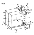
- FIGS. 5 to 10 show a further embodiment of an intended for use in an aircraft galley interface system 10, which in connection with the in the FIGS. 5 to 10 illustrated interface system 10 features also in the interface system 10 according to the FIGS. 1 to 4 can be realized.
- the design of the connecting device 11 is dispensed with a support structure 12 to save additional space and weight.
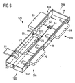
- the first connection element 30 comprises a in FIG. 6 illustrated in detail first portion 30a and shown in Figure 7 in a detailed view second portion 30b.
- the first connection element 30 comprises an aircraft board kitchen connection device 52a, 52b, a first device connection device 54a, 54b and a second device connection device 56a, 56b.
- the aircraft galley connection device 52a, 52b, the first device connection device 54a, 54b and the second device connection device 56a, 56b are also each in two parts, with first sections 52a, 54a, 56a of the aircraft galley connection device 52a, 52b of the first device connection device 54a, 54b and the second device connector 56a, 56b respectively to the first portion 30a of the first terminal member 30 and second portions 52b, 54b, 56b of the aircraft galley connector 52a, 52b, the first device connector 54a, 54b and the second device connector 56a, 56b respectively to the second portion 30b of the first connection element 30 are assigned.
- the first connection element 30 is via the first device connection device 54a, 54b connectable to an internal electrical system, an internal fresh water supply system and an internal sanitation system of the first galley appliance 32. Furthermore, the first connection element 30 can be connected via the second device connection device 56a, 56b to an internal electrical system, an internal fresh water supply system and an internal waste water disposal system of the second galley device 34.
- the first connection element 30 further comprises a likewise two-part distribution system 60a, 60b.
- a first portion 60a of the manifold system 60a, 60b connects the first portion 52a of the aircraft galley fitting 52a, 52b associated with the first portion 30a of the first fitting 30 to the first portions 54a, 56a of the first and second apparatus fittings 54a, 54b, 56a, 56b, see FIG. 6
- a second section 60b of the distribution system 60a, 60b connects the second section 52b of the aircraft galley connection device 52a, 52b to the second section 30b of the first connection element 30 with the second sections 54b, 56b of the first and second device connection devices 54a, 54b, 56a, 56b, see FIG. 7 ,
- the first section 60a of the distribution system 60a, 60b comprises a power distributor 62, which uses an electronic circuit 64 to connect an electrical connection 66 of the first section 52a of the aircraft galley connection device 52a, 52b to an electrical connection 68 of the first section 54a of the first device connection device 54a, 54b and to a first electrical connection 70 of the first section 56a of the second device connection device 56a, 56b, see FIG. 6 .
- the electronic circuit 64 ensures that the total electric power drawn from the galley appliances 32, 34 from the electrical system of the aircraft galley does not exceed a predetermined value.
- the electrical connections 66, 68, 70 may be formed as standardized plug.
- the first section 60a of the distribution system 60a, 60b further comprises a fresh water manifold 72, which via a fresh water pipe system a fresh water connection 76 of the first portion 52a of the aircraft galley connection means 52a, 52b with a fresh water connection 78 of the first section 54a of the first device connection device 54a, 54b and a fresh water connection 80 of first section 56a of the second device connection device 56a, 56b, see Figure 6.
- the fresh water connections 76, 78, 80 prevent unwanted leakage of fresh water when the first portion 30a of the first connection element 30 on the aircraft kitchen side or on board kitchen appliance side is not connected.
- the fresh water pipe system comprises three 90 ° pipe bends, as well as a distributor pipe.
- the second section 60b of the distribution system 60a, 60b includes a sewage manifold 82 having a sewage pipe system 86 of the second portion 52b of the aircraft galley fitting 52a, 52b having a sewage port 88 of the second portion 54b of the first equipment fitting 54a, 54b and a sewage port 90 of the second Section 56b of the second device connector 56a, 56b connects, see FIG. 7 .
- the waste water connections 86, 88, 90 prevent the undesired discharge of wastewater when the second section 30b of the first connection element 30 is not connected to the onboard kitchen or onboard kitchen appliance side.
- the sewage pipe system is formed substantially in the form of a Y-shaped manifold.
- the power distributor 62 and the fresh water distributor 72 are accommodated in a housing 94 of the first section 30 a of the first connection element 30.
- the electronic circuit 64 of the electric power distributor 62 and the fresh water pipe system of the fresh water distributor 72 are securely stowed and protected in a solid housing.
- the electrical connection 66 and the fresh water connection 76 of the first section 52a of the aircraft galley connection device 52a, 52b are arranged separately from one another on a first side surface 96 of the housing 94 which is in the state of the galley appliances 32, 34 of the rear wall 38 of the compartment mounted in the compartment 14 of the aircraft galley 14 and extend in the direction of the rear wall 38 of the compartment 14 (in the opposite direction of x).
- the electrical connections 68, 70 of the first portions 54a, 56a of the device connection devices 54a, 54b, 56a, 56b are arranged separately from each other.
- the fresh water connections 78, 80 of the first sections 54a, 56a of the device connection devices 54a, 54b, 56a, 56b, on the other hand, are in the region of a state which is adjacent to the first and second side surfaces 96, 98 of the housing 94 and mounted in the compartment 14 of the aircraft galley Galley appliances 32, 34 of the bottom plate 22 of the compartment 14 facing the third side surface 100 of the housing 94 is arranged.
- the fresh water manifold 72 and the power distributor 62 are separated from each other by a partition wall 101, so that no water can come into contact with the electronic circuit 64 of the power distributor 62 in the event of a leak in the fresh water pipe system of the fresh water manifold 72.
- the second portion 30b of the first terminal member 30 does not include a housing.
- the waste water connection 86 of the second section 52b of the aircraft galley connection device 52a, 52b also extends in the direction of the rear wall 38 of the galley kitchen 32, 34 mounted in the compartment 14 of the aircraft galley Tray 14 (in the opposite direction of x).
- first connection element 36 of the interface system 10 as well as the first connection element 30, formed in two parts and includes a first portion 36a and a second portion 36b.
- the first section 36a of the second connection element 36 is provided for cooperation with the first section 30a of the first connection element 30a, 30b and comprises a first section 58a of an aircraft galley connection device 58a, 58b, which is complementary to the first section formed on the first section 30a of the first connection element 30 Section 52a of the aircraft galley connection device 52a, 52b is formed.
- the first section 58a of the aircraft galley connecting device 58a, 58b comprises an electrical connection 104 which is provided for interacting with the electrical connection 66 formed on the first section 30a of the first connection element 30a, 30b. Furthermore, the first section 58a of the aircraft galley connection device 58a, 58b comprises a fresh water connection 106 which is provided for cooperation with the fresh water connection 76 formed on the first section 30a of the first connection element 30a, 30b.
- the first section 36a of the second connection element 36 can be fastened in the compartment 14 of the aircraft galley by means of the fastening device 40 which is designed in the form of an L-profile.
- the second section 36b of the second connection element 36 is provided for cooperation with the second section 30b of the first connection element 30a, 30b and comprises a second section 58b of the aircraft galley connection device 58a, 58b, which is complementary to the second section formed on the second section 30b of the first connection element 30 Section 52b of the aircraft galley connector 52a, 52b is formed, see FIG. 7 .
- the second section 58b of the aircraft galley connecting device 58a, 58b comprises a sewage connection 108 which can be fastened to the floor panel 22 or the rear wall 38 of the compartment 14 of the aircraft galley by means of a retaining profile 110 in the form of an L-profile.
- the walls of the housing 94 of the first portion 30a of the first connection element 30a, 30b are reinforced in the region of the second and third side surfaces 98, 100 of the housing 94 and thus form part of the connection device 11, which the first and the second Galley appliances 32, 34 secures their position relative to each other.
- the connecting device 11 comprises a in the Figures 5 and 9
- the support strut 112 is attached to the first and second galley appliances 32, 34 and is located in the compartment mounted in the compartment 14 of the aircraft galley state of the first and second galley appliances 32, 34 in the area of a user accessible front side 114 of the first and the second galley utensil 32, 34.
- the support strut 112 extends substantially parallel to the direction y, ie, in the state mounted in the compartment 14 of the aircraft galley, of the first and second galley appliances 32, 34 parallel to the bottom panel 22 of the compartment 14. Above In addition, the support strut 112 extends substantially the full width of the first and second galley utensils 32, 34 and abuts the side surfaces of the compartment 14.
- the support strut 112 is formed substantially as a hollow body with a rectangular cross-section. In the region of a side wall 116, which abuts in the connected to the galley appliances 32, 34 state of the retaining strut 112 on the front side of the galley appliances 32, 34, the retaining strut 112 is formed reinforced.
- a structural assembly assembled by bolting or bonding the reinforced sidewall 116 of the support strut 112 to the first and second galley appliances 32, 34 from the galley appliances 32, 34 and the support strut 112 is particularly effectively reinforced and / or stiffened by this configuration of the retaining strut 112.
- the connection device 11 of the interface system 10 further comprises a holding device 136.
- the holding device 136 includes a connecting pin 138 and a spacer 140.
- the connecting pin 138 is connected at its first end to the first galley unit 32 and at its second end to the second galley unit 34.
- the connecting pin 138 is received, for example, in a provided on the galley appliances 32, 34 recess and bolted or glued to the galley appliances 32, 34.
- the holding device 136 connects the first galley unit 32 to the second galley unit 34 and holds the first galley unit 32 at a desired distance from the second galley unit 34 by means of the spacer 140.
- a cylindrical guide projection 42 extends from the first fastening means 40, a cylindrical guide projection 42 along the direction x.
- the guide projection 42 is provided to be received in a guide hole 44 formed in the first side surface 96 of the housing 94 of the first portion 30a of the first terminal member 30a, 30b.
- the guide projection 42 and the guide opening 44 form part of the mounting system 15 which secures the first and second galley utensils 32, 34 in position relative to the compartment 14.
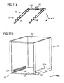
- the mounting system 15 comprises a in FIG. 11a shown first mounting means 16 with two first guide rails 18, 20 which are interconnected by a connecting portion 142.
- the U-shaped structure of the first mounting device 16 has the advantage that by attaching the guide rail 18 to the first galley unit 32 and by attaching the guide rail 20 to the second galley unit 34, the galley appliances 32, 34 based on the connecting portion 142 additionally in position relative to each other be secured.
- the connecting portion 142 further includes a holding structure 144 that extends away from the connecting portion 142 and is configured to receive the waste water manifold 82 of the second portion 30 b of the first connecting member 30.
- the first guide rails 18, 20 of the first mounting device 16 are intended to cooperate with two second guide rails 24a, 24b of the second mounting device 28 of the mounting system 15, see FIG. 11b ,
- the second guide rails 24a, 24b of the second mounting device 28 are fixed to the bottom plate 22 of the compartment 14 of the aircraft galley and extend, as well as the first guide rails 18, 20 of the first mounting device 16, in the direction x.
- the mounting system 15 comprises a securing system with a first securing device 26 assigned to the first mounting device 16 and a second securing device 27 assigned to the second mounting device 28.
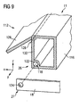
- the first securing device 26 is located in the first securing device 26 FIG. 9 holding strut 112 shown in detail and includes a resiliently biased in its locking position first locking member 118.
- the first locking member 118 includes two cylindrical locking pins which are slidably received in a housing 122.
- the housing 122 is arranged in an edge region of the retaining strut 112.
- the first locking element 118 can be adjusted by moving the locking pins in the direction y between a locking position and an unlocked position.
- the locking pins are housed in the enclosure 122.
- the locking pins project out of the housing 122 and can interact with a second locking element 124 of a second securing device 27 assigned to the second mounting device 28.
- the second locking element 124 of the second securing device 27 comprises two bores formed in the second guide rails 24a, 24b, see Figures 9 and 11b ,
- the locking pins are received in the bores of the second locking element 124, whereby an undesirable displacement of the galley appliances 32, 34 is securely prevented in the compartment 14 of the aircraft galley.
- the first securing device 26 of the first mounting device 16 further comprises an actuating element 126 for adjusting the first locking element 118 between its locking position and its unlocked position.
- the actuator 126 is a in FIG. 9 not shown in detail connecting element connected to the first locking element 118 and pivotable about an axis 128 between an unactuated position and an actuating position, wherein the actuating element 126 in its operating position, the first locking element 118 holds against the spring applied to the first locking member 118 force in its unlocked position and holds in its unactuated position, the first locking element 118 in its locked position and / or leaves.
- the axis 128 is oriented in the direction y and received in an edge of the retaining strut 112.
- the actuator 126 extends in the direction y substantially over the length of the support strut 112 and thus substantially the entire width of the front side 114 of the first and second galley kitchen device 32, 34th
- the actuator 126 In its unactuated position, the actuator 126 abuts a side surface 132 of the support strut 112 and thus extends substantially parallel to the side surface 132 of the support strut 112 and thus the front side 114 of the galley appliances 32, 34. In his in FIG. 9 shown operating position, the actuator 126, however, folded in the direction z upwards and extends at an angle of about 60 ° to the side surface 132 of the support strut 112 and consequently the front 114 of the galley appliances 32, 34. In its operating position, it can be used as a handle be, for example, to pull out the galley appliances 32, 34 from the compartment 14 of the aircraft galley.
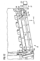
- FIG. 12 shows a further embodiment of a security system with a first and a second securing means 26, 27.
- Components of the first and second securing devices 26, 27 arranged in the region of a side wall of the galley appliance 32. Further components of the first and second securing devices 26, 27 are provided in the area of a side wall of the galley appliance 34 opposite the side wall of the galley appliance 32 in FIG. 12 illustrated components are configured.
- the first securing device 26 comprises a first locking element 118 which is rotatably supported by means of a first pivot bearing 146.
- a spring element 148 bears against an immovable part 150 and exerts a compressive force on a rotatable part 152 of the first locking element 118, as a result of which the first locking element 118 engages in its Locking position is biased.
- the first locking element 118 further includes a hook profile 154 and a guide slope 156.
- the second securing device 27 is attachable to a lower portion of a side wall of the compartment 14 of the aircraft galley and includes a second locking element 124 having a hook profile 154 of the first locking element 118 adapted locking projection 158, which extends in mounted in the compartment 14 of the aircraft galley state of the second securing means 27 of the first locking member 118 in the compartment 14 of the aircraft galley.
- the locking projection 158 of the second locking member 124 When inserting the galley appliances 32, 34 in the compartment 14 of the aircraft galley presses the locking projection 158 of the second locking member 124 on the guide slope 156 of the first locking member 118 and thus moves the first locking member 118 against the force of the spring 148 in its unlocked position.
- the locking projection 158 When the galley appliances 32, 34 have reached their intended position in the compartment 14 of the aircraft galley, the locking projection 158 is in a position that allows the first locking member 118 to move into its locked position due to its resilient bias and the hook profile 154 of the first locking member 118 can engage behind the locking projection 158.
- the first locking element 118 and the second locking element 124 thus engage automatically during assembly of the galley appliances 32, 34 in the compartment 14 of the aircraft galley.
- An actuating element 126 of the first securing device 26 is arranged in the region of the front side 114 of the galley appliances 32, 34 and rotatably supported by means of a second pivot bearing 160.
- the actuating element 126 is connected to the first locking element 118 via a rigid connecting element 134 extending along the lower edge of the side surface of the galley appliance 32 and displaceably mounted within a pole shaft.
- An actuation of the actuating element 126 takes place by manually folding out the actuating element 126.
- the actuating element 126 describes a rotational movement in the xz plane about the second rotary bearing 160.
- An actuating nose 164 formed on the actuating element 126 engages in a first rod groove 166 of the connecting element 134 , thereby causing a displacement of the connecting element 134 along the direction x.
- a second rod groove 168 of the connecting element 134 which encompasses a lever arm 170 of the first locking element 118, causes a rotation of the first locking element 118 in the xz plane about the first pivot bearing 146 when the connecting element 134 is displaced.
- the first locking element 118 is counter to the first locking element 118 Federschreib of the spring element 148 adjusted in its unlocked position.
- the interface system 10 may only be one in FIG. 9 shown security system or only one in FIG. 12 include security system shown. However, it is also possible, the interface system 10 both with an in FIG. 9 shown security system as well with an in FIG. 12 equipped security system shown.
- FIG. 13 shows a further embodiment of an interface system 10, wherein the first connection element 30 of the interface system 10 is connected to two superposed galley appliances 32, 34 to a device module.
- the connection means 11 of the interface system 10 includes a mounting plate 172 which is attached to the first and second galley unit 32, 34 and mounted in the compartment 14 of the aircraft galley state of the first and second galley kitchen appliances 32, 34 is arranged in the region of a lateral surface of the compartment 14 facing side surfaces of the first and second galley kitchen appliances 32, 34.
- the first section 30a of the first connection element 30 comprises a first section 52a of an aircraft galley connection device which is directly connected only to a first section 54a of a first device connection device.
- the first portion 60a of the distribution system is configured to connect the first portion 54a of the first equipment connection device directly connected to the first portion 52a of the aircraft galley connection device to a first portion 56a of a second equipment connection device not directly connected to the first portion 52a of the aircraft galley connection device.
- FIG. 13 not illustrated in detail second portion 30 b of the first connection element 30 a second portion of the convinced, which is directly connected only to a second portion of the second device connecting device.
- the second portion of the distribution system is configured to connect the second portion of the second equipment terminal directly connected to the second portion of the aircraft galley terminal to a second portion of the first equipment terminal not directly connected to the second portion of the aircraft galley terminal.
- FIG. 14 shows a further alternative embodiment of a device module.
- the device module comprises three galley appliances 32, 34, 174, wherein the first and the second galley appliances 32, 34 are provided to be arranged side by side in a front region of the compartment 14 of the aircraft galley facing the compartment opening.
- the third galley appliance 174 is provided for arrangement in a rear region of the compartment 14 facing away from the compartment opening.
- Such a configuration of the device module is preferably suitable in the case where it is not desired or necessary to make the third galley device 174 directly accessible to a user.
- the third galley appliance 174 may be a water heater, which is, inter alia, adapted to receive fresh water from the aircraft galley, to heat it, and then to supply it to the first and second galley appliances 32, 34.
- the third galley appliance 174 is arranged in a frame-shaped holding structure 176, which makes it possible to connect the first section 30a of the first connection element 30 via corresponding lines to the first section 36a of the second connection element 36.
Landscapes
- Engineering & Computer Science (AREA)
- Aviation & Aerospace Engineering (AREA)
- Sink And Installation For Waste Water (AREA)
- Connection Of Plates (AREA)
- Switch Cases, Indication, And Locking (AREA)
Description
- Die vorliegende Erfindung betrifft ein zur Verwendung in einer Flugzeugbordküche vorgesehenes Schnittstellensystem, ein ein derartiges Schnittstellensystem umfassendes und zur Aufnahme in einer Flugzeugbordküche vorgesehenes Gerätemodul, sowie ein Verfahren zur Montage von Bordküchengeräten in einer Flugzeugbordküche.
- Aus der
WO 2007/096000 A1 ist eine modular aufgebaute Flugzeugbordküche bekannt, die einen Grundkörper mit einer Mehrzahl von Fächern umfasst. In den Fächern des Grundkörpers sind verschiedene Geräte, wie z.B. Öfen, Mikrowellengeräte, Wassererhitzer und Getränkezubereiter angeordnet. Ferner sind in den Fächern des Grundkörpers mehrere hintereinander angeordnete Boxen aufgenommen, in denen zur Versorgung der Passagiere an Bord des Flugzeugs benötigte Serviceprodukte, wie z.B. Nahrungsmittel oder Getränke untergebracht werden können. - Die
DE 10 2006 023 047 A1 , welche als der nächstliegende, bekannte Stand der Technik betrachtet wird, offenbart eine modulare Flugzeugbordküche mit in Fächern der Bordküche vorgesehenen Schnittstellenelementen zum Anschluss von Bordküchengeräten an ein elektrisches Versorgungsnetz sowie ein Wasserversorgungsnetz der Bordküche. - Der Erfindung liegt die Aufgabe zugrunde, ein Schnittstellensystem, gemäβ Anspruch 1, bereitzustellen, das es ermöglicht, Bordküchengeräte einfach, platzsparend und flexibel in einem Fach einer Flugzeugbordküche zu installieren. Ferner liegt der Erfindung die Aufgabe zugrunde, ein ein derartiges Schnittstellensystem umfassendes und zur Aufnahme in einer Flugzeugbordküche vorgesehenes Gerätemodul anzugeben, Außerdem liegt der Erfindung die Aufgabe zugrunde, ein Verfahren, gemäβ Anspruch 14, zur Montag von Borbküchengeräten in einer Flugzeugbordküche anzugeben.
- Ein erfindungsgemäßes Schnittstellensystem zur Verwendung in einer Flugzeugbordküche umfasst ein erstes Anschlusselement, das über eine erste Geräteanschlusseinrichtung mit einem internen elektrischen System, einem internen Frischwasserversorgungssystem und/oder einem internen Abwasserentsorgungssystem eines ersten Bordküchengeräts verbindbar ist und über eine zweite Geräteanschlusseinrichtung mit einem internen elektrischen System, einem internen Frischwasserversorgungssystem und/oder einem internen Abwasserversorgungssystem eines zweiten Bordküchengeräts verbindbar ist. Das erste Anschlusselement ist ferner über eine Flugzeugbordküchenanschlusseinrichtung mit einer komplementären Flugzeugbordküchenanschlusseinrichtung eines in einem Fach einer Flugzeugbordküche befestigbaren zweiten Anschlusselements verbindbar, um das erste Anschlusselement über das zweite Anschlusselement mit einem elektrischen System, einem Frischwasserversorgungssystem und/oder einem Abwasserentsorgungssystem der Flugzeugbordküche zu verbinden. Das erste Anschlusselement umfasst außerdem ein Verteilersystem, das die Flugzeugbordküchenanschlusseinrichtung des ersten Anschlusselements mit der ersten und der zweiten Geräteanschlusseinrichtung des ersten Anschlusselements verbindet.
- Das erfindungsgemäße Schnittstellensystem ermöglicht es, über das erste Anschlusselement auf einfache Weise eine Verbindung zwischen dem internen elektrischen System, dem internen Frischwasserversorgungssystem und/oder dem internen Abwasserentsorgungssystem des ersten Bordküchengeräts und dem elektrischen System, dem Frischwasserversorgungssystem und/oder dem Abwasserentsorgungssystem der Flugzeugbordküche sowie eine Verbindung zwischen dem internen elektrischen System, dem internen Frischwasserversorgungssystem und/oder dem internen Abwasserentsorgungssystem des zweiten Bordküchengeräts und dem elektrischen System, dem Frischwasserversorgungssystem und/oder dem Abwasserentsorgungssystem der Flugzeugbordküche herzustellen. Mit anderen Worten, das erfindungsgemäße Schnittstellensystem stellt sicher, dass die internen Systeme einer Mehrzahl von Bordküchengeräten auf einfache Weise mit den entsprechenden Systemen der Flugzeugbordküche verbunden werden können.
- Grundsätzlich können mittels des erfindungsgemäßen Schnittstellensystems mindestens zwei Bordküchengeräte an ein elektrisches System, ein Frischwasserversorgungssystem und/oder ein Abwasserentsorgungssystem der Flugzeugbordküche angeschlossen werden, wobei die Bordküchengeräte, je nach Bedarf, jeweils an alle drei Flugzeugbordküchensysteme oder nur an ein oder zwei Flugzeugbordküchensystem(e) angeschlossen werden können. Beispielsweise kann auf den Anschluss eines Bordküchengeräts an ein Frischwasserversorgungssystem und/oder ein Abwasserentsorgungssystem der Flugzeugbordküche verzichtet werden, wenn das Bordküchengerät im Betrieb kein Wasser verbraucht und/oder kein Abwasser erzeugt und daher kein internes Fischwasserversorgungssystem und/oder kein internes Abwasserentsorgungssystem umfasst. Ferner kann das erfindungsgemäße Schnittstellensystem auch dazu eingerichtet sein, mehr als zwei Bordküchengeräte an ein elektrisches System, ein Frischwasserversorgungssystem und/oder ein Abwasserentsorgungssystem der Flugzeugbordküche anzuschließen. Hierzu muss das Schnittstellensystem lediglich eine entsprechende Anzahl von Geräteanschlusseinrichtungen und ein entsprechend gestaltetes Verteilersystem aufweisen.
- Das erfindungsgemäße Schnittstellensystem bietet die Möglichkeit, zwei oder mehr Bordküchengeräte über ein einziges in dem Fach der Flugzeugbordküche angeordnetes zweites Anschlusselement mit dem elektrischen System, dem Frischwasserversorgungssystem und/oder dem Abwasserentsorgungssystem der Flugzeugbordküche zu verbinden. Daher kann das erfindungsgemäße Schnittstellensystem besonders vorteilhaft in bereits bestehenden Flugzeugbordküchen eingesetzt werden, in denen das zweites Anschlusselement ursprünglich für die Versorgung von lediglich einem einzigen Bordküchengerät vorgesehenen war oder in denen pro Fach nur ein zweites Anschlusselement vorgesehen ist, es jedoch erforderlich oder erwünscht ist, ohne Installation weiterer zweiter Anschlusselemente mehr als ein Bordküchengerät mit dem elektrischen System, dem Frischwasserversorgungssystem und/oder dem Abwasserentsorgungssystem der Flugzeugbordküche zu verbinden. Dadurch kann der in einer Flugzeugbordküche zur Aufnahme von Bordküchengeräten zur Verfügung stehende Raum besonders gut und vielseitig genutzt werden.
- Die Bordküchengeräte können beispielsweise als Ofen, als Mikrowellengerät, als Toaster, als Wassererhitzer, als Babynahrungszubereiter, als Heißgetränkezubereiter, als Wassertank, als Wasserspender, als Stauraumbehälter oder dergleichen ausgebildet sein. Der Verwendungszweck des ersten Bordküchengeräts kann der gleiche sein wie der des zweiten Bordküchengeräts oder sich von letzterem unterscheiden. Zum Beispiel kann das Schnittstellensystem dazu eingerichtet sein, eine Bordküchengerätekombination aus einem Mikrowellengerät und einem Heißgetränkezubereiter mit der Flugzeugbordküche zu verbinden.
- Das zweite Anschlusselement des erfindungsgemäßen Schnittstellensystems ist vorzugsweise in einer derartigen Position in dem Fach der Flugzeugbordküche befestigbar und das erste Anschlusselements ist vorzugsweise in einer derartigen Position mit den Bordküchengeräten verbindbar, dass bei der Montage der mit dem ersten Anschlusselement verbundenen Bordküchengeräte in dem Fach der Flugzeugbordküche das erste Anschlusselement im Wesentlichen automatisch mit dem zweiten Anschlusselement zusammenwirkt. Mit anderen Worten, durch das erfindungsgemäße Schnittstellensystem kann ein Plug-and-Play-System geschaffen werden, das eine besonders einfache Montage und Inbetriebnahme der Flugzeugbordküchengeräte ermöglicht.
- Ferner können mit Hilfe des erfindungsgemäßen Schnittstellensystems mehrere Bordküchengeräte in einem Arbeitsschritt in der Flugzeugbordküche montiert werden, wobei Montagearbeiten zum Anschließen der internen elektrischen Systeme, der internen Frischwasserversorgungssysteme und/oder der internen Abwasserentsorgungssysteme der Bordküchengeräte an das erste Anschlusselement auf komfortable Art und Weise außerhalb der Flugzeugbordküche durchgeführt werden können. Schließlich ermöglicht das erfindungsgemäße Schnittstellensystem eine Entkopplung der bordküchengeräteinternen elektrischen Anschlüsse, Frischwasserversorgungs- und/oder Abwasserentsorgungsanschlüsse von den entsprechenden Anschlüssen der Flugzeugbordküche, so dass die Bordküchengeräte besonders flexibel an verschiedenen Positionen in der Flugzeugbordküche montiert werden können.
- Das Verteilersystem des ersten Anschlusselements kann beispielsweise einen Stromverteiler, einen Frischwasserverteiler und/oder einen Abwasserverteiler umfassen. Vorzugsweise verbindet der Stromverteiler des ersten Anschlusselements einen elektrischen Anschluss der Flugzeugbordküchenanschlusseinrichtung des ersten Anschlusselements mit einem elektrischen Anschluss der ersten Geräteanschlusseinrichtung des ersten Anschlusselements und mit einem elektrischen Anschluss der zweiten Geräteanschlusseinrichtung des ersten Anschlusselements. Der Frischwasserverteiler des ersten Anschlusselements verbindet vorzugsweise einen Frischwasseranschluss der Flugzeugbordküchenanschlusseinrichtung des ersten Anschlusselements mit einem Frischwasseranschluss der ersten Geräteanschlusseinrichtung des ersten Anschlusselements und mit einem Frischwasseranschluss der zweiten Geräteanschlusseinrichtung des ersten Anschlusselements. Der Abwasserverteiler des ersten Anschlusselements verbindet vorzugsweise einen Abwasseranschluss der ersten Geräteanschlusseinrichtung des ersten Anschlusselements und einen Abwasseranschluss der zweiten Geräteanschlusseinrichtung des ersten Anschlusselements mit einem Abwasseranschluss der Flugzeugbordküchenanschlusseinrichtung des ersten Anschlusselements.
- Das erste Anschlusselement und insbesondere das Verteilersystem des ersten Anschlusselements können verschieden gestaltet sein. In einer Ausführungsform umfasst das erste Anschlusselement ein Gehäuse, an dessen Seitenwänden die Flugzeugbordküchenanschlusseinrichtung sowie die Geräteanschlusseinrichtungen angeordnet sein können. Das Verteilersystem kann dann in das Gehäuse des ersten Anschlusselements integriert sein und die Flugzeugbordküchenanschlusseinrichtung direkt mit allen Geräteanschlusseinrichtungen des ersten Anschlusselements verbinden.
- Alternativ dazu kann das erste Anschlusselement jedoch auch eine Flugzeugbordküchenanschlusseinrichtung umfassen, die mit lediglich einer Geräteanschlusseinrichtung oder mit lediglich einem Teil der Geräteanschlusseinrichtungen des ersten Anschlusselements direkt verbunden ist. Das Verteilersystem des ersten Anschlusselements ist dann vorzugsweise so gestaltet, dass es die direkt mit der Flugzeugbordküchenanschlusseinrichtung verbundene(n) Geräteanschlusseinrichtung(en) mit der/den nicht unmittelbar an die Flugzeugbordküchenanschlusseinrichtung angeschlossenen Geräteanschlusseinrichtung(en) des ersten Anschlusselements verbindet. Das Verteilersystem kann dann zumindest teilweise in ein Bordküchengerät integriert sein, das über eine entsprechende Geräteanschlusseinrichtung zum direkten Anschluss an die Flugzeugbordküchenanschlusseinrichtung des ersten Anschlusselements vorgesehen ist. Das erfindungsgemäße Schnittstellensystem kann somit besonders gut auf verschiedene räumliche Anordnungen und funktionale Kombinationen der Bordküchengeräte angepasst werden.
- Der Stromverteiler des ersten Anschlusselements kann beispielsweise elektrische Leitungen, Kabel, Elektronikplatinen, Schaltkreise oder dergleichen umfassen. Vorzugsweise speist der Stromverteiler des ersten Anschlusselements die von dem elektrischen System der Flugzeugbordküche bezogene elektrische Energie entsprechend der von den Bordküchengeräten verbrauchten Energie separat in die Bordküchengeräte ein. Dabei kann das erste Anschlusselements dazu eingerichtet sein, sicherzustellen, dass ein vorgegebenes Maximum an von den Bordküchengeräten verbrauchter elektrischer Gesamtleistung nicht überschritten wird.
- Der Frischwasserverteiler des ersten Anschlusselements kann beispielsweise Wasserleitungen in Form von Rohren oder Schläuchen, Flansche, Muffen, gebogene Rohrabschnitte, T-förmige Verteilerstücke, Y-förmige Verteilerstücke, Dichtungen, Kanäle, Ventile, Klappen, Durchflussregelventile, Rückschlagventile, Auslaufbruchsicherungskupplungen, Rohrkopplungen oder dergleichen umfassen. Vorzugsweise speist der Frischwasserverteiler das Frischwasser entsprechend der von den Bordküchengeräten verbrauchten Wassermenge separat in die Bordküchengeräte ein.
- Ebenso kann der Abwasserverteiler des ersten Anschlusselements Wasserleitungen in Form von Rohren oder Schläuchen, Flansche, Muffen, gebogene Rohrabschnitte, T-förmige Verteilerstücke, Y-förmige Verteilerstücke, Dichtungen, Kanäle, Ventile, Klappen, Durchflussregelventile, Rückschlagventile, Auslaufbruchsicherungskupplungen oder Rohrkopplungen umfassen. Der Abwasserverteiler des ersten Anschlusselements bezieht von den Bordküchengeräten Abwasser und leitet das Abwasser in das Abwassersystem der Flugzeugbordküche ab. Der Abwasserverteiler kann beispielsweise auch derart ausgebildet sein, dass er die Abwasseranschlüsse der ersten und der zweiten Geräteanschlusseinrichtung des ersten Anschlusselements mit einem Abwasserspeicherbehälter zum Zwischenspeichern von Abwasser verbindet.
- In einer bevorzugten Ausführung des erfindungsgemäßen Schnittstellensystems sind die Frischwasseranschlüsse der ersten und der zweiten Geräteanschlusseinrichtung des ersten Anschlusselements in einem ersten Abschnitt des ersten Anschlusselements angeordnet, während die Abwasseranschlüsse der ersten und der zweiten Geräteanschlusseinrichtung des ersten Anschlusselements in einem separat von dem ersten Abschnitt des ersten Anschlusselements ausgebildeten zweiten Abschnitt des ersten Anschlusselement angeordnet sind. Der erste und der zweite Abschnitt des ersten Anschlusselements sind dann in unterschiedlichen Positionen mit den Bordküchengeräten verbindbar. Dadurch wird es möglich, bei der Zuleitung von Frischwasser zu und/oder der Ableitung von Abwasser von den Bordküchengeräten die Schwerkraft zu nutzen. Beispielsweise kann der erste Abschnitt des ersten Anschlusselements zur Montage in einem oberen Abschnitt der Bordküchengeräte und der zweite Abschnitt des ersten Anschlusselements zur Montage in einem unteren Abschnitt der Bordküchengeräte vorgesehen sein.
- Zusätzlich oder alternativ dazu ist es denkbar, die elektrischen Anschlüsse der ersten und der zweiten Geräteanschlusseinrichtung des ersten Anschlusselements in einem Abschnitt des ersten Anschlusselements anzuordnen, der separat von einem Abschnitt des ersten Anschlusselements zur Aufnahme der Frischwasseranschlüsse und der Abwasseranschlüsse der ersten und der zweiten Geräteanschlusseinrichtung des ersten Anschlusselements ausgebildet ist. Dadurch wird eine räumliche Trennung von elektrischen Anschlüssen und Wasseranschlüssen ermöglicht und somit verhindert, dass bei einem Leck eines Wasseranschlusses ein elektrischer Kurzschluss verursacht wird.
- Vorzugsweise umfasst das erfindungsgemäße Schnittstellensystem eine Verbindungseinrichtung, welche das erste und das zweite Bordküchengerät in deren Position relativ zueinander sichert. Die Verbindungseinrichtung kann dazu eingerichtet sein, mit den Bordküchengeräten durch Verschrauben oder Verkleben oder mittels einer Steckverbindung verbunden zu werden. Mit Hilfe der Verbindungseinrichtung des erfindungsgemäßen Schnittstellensystems können die Bordküchengeräte vor ihrer Montage in dem Fach der Flugzeugbordküche zu einer eigenständig handhabbaren Baugruppe vormontiert werden.
- In einer bevorzugten Ausführung des erfindungsgemäßen Schnittstellensystems umfasst die Verbindungseinrichtung eine Trägerstruktur, die dazu eingerichtet ist, das erste und das zweite Bordküchengerät aufzunehmen. Die Trägerstruktur kann eine Grundform aufweisen, die an die Form des Fachs der Flugzeugbordküche angepasst ist, in dem die Bordküchengeräte montiert werden soll. Beispielsweise kann die Grundform der Trägerstruktur quaderförmig ausgeführt sein. Vorzugsweise ist die Breite der Trägerstruktur an die Breite des Fachs der Flugzeugbordküche angepasst, so dass die Bordküchengeräte sicher in dem Fach der Flugzeugbordküche montiert werden können. Falls gewünscht, kann zusätzlich auch die Höhe und/oder die Tiefe der Trägerstrukturgrundform an die Höhe beziehungsweise Tiefe des Fachs der Flugzeugbordküche angepasst sein. Dadurch wird eine optimale Ausnutzung des für Bordküchengeräte in der Flugzeugbordküche zur Verfügung stehenden Einbauraums gewährleistet.
- Die Trägerstruktur des erfindungsgemäßen Schnittstellensystems kann beispielsweise eine Mehrzahl von Streben umfassen. Eine im Wesentlichen durch Streben gebildete Trägerstruktur ist besonders leichtgewichtig zu realisieren. Um der Trägerstruktur die erforderliche Steifigkeit zu verleihen, kann die Trägerstruktur beispielsweise neben Seitenflächen der beispielsweise quaderförmige Grundform der Trägerstruktur definierenden Horizontal- und Vertikalstreben versteifende Diagonalstreben umfassen. Die Streben der Trägerstruktur können auf jede geeignete Weise mit den Bordküchengeräten verbunden werden. Beispielsweise können die Streben der Trägerstruktur mit den Bordküchengeräten verschraubt werden. Die Streben der Trägerstruktur können, falls gewünscht, auch als Hohlstreben ausgebildet sein. Dadurch kann das Gewicht der Trägerstruktur weiter reduziert werden. Darüber hinaus können die Streben bei Bedarf elektrische Leitungen und/oder Wasserleitungen aufnehmen oder sogar selbst als wasserführende Leitungen dienen.
- Alternativ oder zusätzlich zu der Trägerstruktur kann die Verbindungseinrichtung des erfindungsgemäßen Schnittstellensystems einen Abschnitt eines Gehäuses des ersten Anschlusselements umfassen, an dem das erste und das zweite Bordküchengerät befestigt werden können. Beispielsweise kann der Gehäuseabschnitt des ersten Anschlusselements ein verstärkter Gehäuseabschnitt sein, an den die Bordküchengeräte geschraubt oder geklebt werden können. Ferner kann im Bereich des Gehäuseabschnitts des ersten Anschlusselements die Flugzeugbordküchenanschlusseinrichtung des ersten Anschlusselements angeordnet sein. Falls gewünscht oder erforderlich, kann/können ein Gehäuse eines Bordküchengeräts oder die Gehäuse der Bordküchengeräte eine an die Form des Gehäuse des ersten Anschlusselements angepasste Ausnehmung zur Aufnahme des Gehäuses des ersten Anschlusselements aufweisen.
- Vorzugsweise umfasst die Verbindungseinrichtung des erfindungsgemäßen Schnittstellensystems ferner eine Haltevorrichtung, welche einen oder mehrere mit dem ersten und dem zweiten Bordküchengerät verbindbare(n) Verbindungsstift(e) sowie einen oder mehrere von dem/den Verbindungsstift(n) getragene(n) Abstandshalter umfasst. Der Verbindungsstift kann beispielsweise durch Einstecken, Verkleben oder Verschrauben mit den Bordküchengeräten verbunden werden. Die Haltevorrichtung ermöglicht es, zwei benachbarte Bordküchengeräte unter Einhaltung eines durch den Abstandshalter vorgegebenen Abstands zwischen den benachbarten Bordküchengeräten miteinander zu verbinden. Somit ist es anhand der Haltevorrichtung beispielsweise möglich, Sicherheits-, Kühlungs- und/oder Lüftungsspalte zwischen den Bordküchengeräten zu realisieren.
- In einer bevorzugten Ausführungsform des erfindungsgemäßen Schnittstellensystems umfasst die Verbindungseinrichtung ferner eine Haltestrebe. Das erste und das zweite Bordküchengerät können derart an der Haltestrebe befestigt werden, dass die Haltestrebe im in dem Fach der Flugzeugbordküche montierten Zustand der ersten und des zweiten Bordküchengeräts im Bereich einer einem Nutzer zugänglichen Frontseite des ersten und des zweiten Bordküchengeräts angeordnet ist und sich im Wesentlichen parallel zu der Bodenplatte des Fachs erstreckt. Im in dem Fach der Flugzeugbordküche montierten Zustand der Bordküchengeräte kann sich die Haltestrebe beispielsweise im Bereich einer Unterkante des Fachs entlang der Frontseite der Bordküchengeräte über die gesamte Breite des Fachs erstrecken. Die Haltestrebe kann zum Beispiel als L-Profil, U-Profil oder Hohlkörper, insbesondere aber als quaderförmiger Hohlkörper ausgebildet sein. Ferner kann die Haltestrebe einen verstärkten Abschnitt aufweisen mit dem die Bordküchengeräte durch Verschrauben, Verkleben oder eine sonstige Verbindungstechnik verbunden werden können.
- Schließlich kann die Verbindungseinrichtung eine Befestigungsplatte umfassen. Das erste und das zweite Bordküchengerät können derart mit der Befestigungsplatte verbunden werden, dass die Befestigungsplatte im in dem Fach der Flugzeugbordküche montierten Zustand des ersten und des zweiten Bordküchengeräts im Bereich einer Seitenfläche des Fachs zugewandten Seitenflächen des ersten und des zweiten Bordküchengeräts angeordnet ist. Mit anderen Worten, im in dem Fach der Flugzeugbordküche montierten Zustand des ersten und des zweiten Bordküchengeräts kann die Befestigungsplatte zwischen einer Seitenfläche des Fachs und dieser Seitenfläche gegenüberliegenden Seitenflächen der Bordküchengeräte angeordnet sein und sich parallel zu diesen Flächen erstrecken. Eine Befestigungsplatte ermöglicht insbesondere das Verbinden von zwei Bordküchengeräten, von denen das erste im in dem Fach der Flugzeugbordküche montierten Zustand im oberen Bereich des Fachs angeordnet ist, während das zweite Bordküchengerät unterhalb des ersten Bordküchengeräts in einem unteren Bereich des Fachs angeordnet ist. Die Befestigungsplatte kann beispielsweise als durchgängige Platte, als Versteifungsstruktur oder als Gitter ausgebildet sein oder mehrere Streben umfassen und durch Verschrauben oder Verkleben an den Bordküchengeräten befestigbar sein.
- Eine weitere bevorzugte Ausführungsform des erfindungsgemäßen Schnittstellensystems umfasst ein Montagesystem mit einer ersten und einer zweiten Montageeinrichtung. Die erste Montageeinrichtung ist unmittelbar oder mittelbar, beispielsweise über eine Trägerstruktur der Verbindungseinrichtung, an dem ersten und/oder dem zweiten Bordküchengerät befestigbar. Die zu der ersten Montageeinrichtung komplementäre zweite Montageeinrichtung kann dazu eingerichtet sein, in dem Fach der Flugzeugbordküche angebracht zu werden und mit der ersten Montageeinrichtung zusammenzuwirken, um das erste und das zweite Bordküchengerät in deren Position relativ zu dem Fach der Flugzeugbordküche zu sichern. Bei einer derartigen Gestaltung eines Montagesystems können die Bordküchengeräte auf komfortable Weise außerhalb des Fachs der Flugzeugbordküche mit der ersten Montageeinrichtung verbunden werden. In einem separaten Arbeitsschritt kann die zweite Montageeinrichtung in dem Fach der Flugzeugbordküche angebracht werden. Schließlich können die Bordküchengeräte in das Fach der Flugzeugbordküche eingebracht und durch das Zusammenwirken der an den Bordküchengeräten angebrachten ersten Montageeinrichtung mit der in dem Fach der Flugzeugbordküche befestigten zweiten Montageeinrichtung in dem Fach der Flugzeugbordküche befestigt werden. Dadurch kann zuverlässig verhindert werden, dass sich die Bordküchengeräte ungewollt aus ihrer vorgesehenen Position bewegen oder aus dem Fach der Flugzeugbordküche herausfallen.
- Vorzugsweise umfasst die erste Montageeinrichtung des Montagesystems eine erste Führungsschiene, die dazu eingerichtet ist, bei der Montage der Bordküchengeräte in dem Fach der Flugzeugbordküche sowie im in dem Fach der Flugzeugbordküche montierten Zustand der Bordküchengeräte mit einer zweiten Führungsschiene der zweiten Montageeinrichtung zusammenzuwirken. Bei der Montage der Bordküchengeräte in dem Fach der Flugzeugbordküche kann beispielsweise die erste Führungsschiene der ersten Montageeinrichtung verschiebbar in der zweiten Führungsschiene der zweiten Montageeinrichtung aufgenommen werden. Die Bordküchengeräte können dann auf einfache Weise durch Einschieben in das Fach der Flugzeugbordküche eingebracht werden. Die erste Montageeinrichtung umfasst vorzugsweise zwei erste Führungsschienen, die sich im an einem Bordküchengerät oder den Bordküchengeräten befestigten Zustand im Wesentlichen parallel zueinander und parallel zu einer Längsachse des Bordküchengeräts/der Bordküchengeräte erstrecken können. In ähnlicher Weise kann die zweite Montageeinrichtung zwei zweite Führungsschienen umfassen, die sich im in dem Fach der Flugzeugbordküche montierten Zustand im Wesentlichen parallel zueinander und parallel zu einer Längsachse des Fachs erstrecken können.
- Die zweite(n) Führungsschiene(n) der zweiten Montageeinrichtung kann/können beispielsweise an einem äußeren Rand einer Bodenplatte des Fachs der Flugzeugbordküche befestigbar sein. Alternativ dazu kann/können die zweite(n) Führungsschiene(n) der zweiten Montageeinrichtung auch an einer Seitenwand des Flugzeugbordküchenfachs anbringbar sein, wobei die zweite(n) Führungsschiene(n) der zweiten Montageeinrichtung dann vorzugsweise in einem unteren Bereich der Seitenwand des Flugzeugbordküchenfachs anbringbar ist/sind, der der Bodenplatte des Flugzeugbordküchenfachs zugewandt ist. Die Anordnung der ersten Führungsschiene(n) der ersten Montageeinrichtung an dem/den mit dem erfindungsgemäßen Schnittstellenssystem verbundenen ersten und/oder zweiten Bordküchengerät(en) ist vorzugsweise an die Position der zweiten Führungsschiene(n) der zweiten Montageeinrichtung in dem Fach der Flugzeugbordküche angepasst. Eine besonders einfache Montage der Bordküchengeräte in dem Fach der Flugzeugbordküche ist dann möglich, wenn zwei erste Führungsschienen der ersten Montageeinrichtung beispielsweise an einander gegenüberliegenden Seitenflächen der Bordküchengeräte angebracht sind, die im in dem Fach der Flugzeugbordküche angeordneten Zustand der Bordküchengeräte Seitenwänden des Flugzeugbordküchenfachs zugewandt sind. Zwei komplementäre Führungsschienen der zweiten Montageeinrichtung sind dann vorzugsweise in einer entsprechenden Höhe an der Bodenplatte oder den Seitenwänden des Fachs der Flugzeugbordküche befestigt.
- Das Montagesystem umfasst vorzugsweise ferner einen Führungsvorsprung, der sich von dem ersten Anschlusselement oder von einer Befestigungseinrichtung zur Befestigung des zweiten Anschlusselements in dem Fach der Flugzeugbordküche erstreckt. Der Führungsvorsprung ist dazu eingerichtet, im in dem Fach der Flugzeugbordküche montierten Zustand der Bordküchengeräte in einer zu dem Führungsvorsprung komplementären Führungsöffnung aufgenommen zu werden, die in der Befestigungseinrichtung zur Befestigung des zweiten Anschlusselements in dem Fach der Flugzeugbordküche oder in dem ersten Anschlusselement ausgebildet ist. Die Aufnahme des Führungsvorsprungs in der Führungsöffnung gewährleistet eine sichere Positionierung der Bordküchengeräte in dem Fach der Flugzeugbordküche. Dabei werden auch das erste und das zweite Anschlusselement korrekt zueinander ausgerichtet, so dass das erste und das zweite Anschlusselement mehr oder weniger automatisch miteinander verbunden werden, sobald die Bordküchengeräte die gewünschte Position in dem Flugzeugbordküchenfach erreicht haben. Der Führungsvorsprung kann zum Beispiel durch einen zylinderförmigen oder U-Profil-förmigen Körper gebildet werden. In ähnlicher Weise kann die Führungsöffnung durch eine im Wesentlichen zylinderförmige Ausnehmung gebildet werden oder als U-Profil-förmige Führungsnut ausgebildet sein.
- Vorzugsweise umfasst die erste Montageeinrichtung des Montagesystems ferner eine mit dem ersten und/oder dem zweiten Bordküchengerät verbindbare erste Sicherungseinrichtung sowie eine zu der ersten Sicherungseinrichtung der ersten Montageeinrichtung komplementäre zweite Sicherungseinrichtung. Die zweite Sicherungseinrichtung bildet vorzugsweise eine Komponente der zweiten Montageeinrichtung und ist vorzugsweise dazu eingerichtet ist, in dem Fach der Flugzeugbordküche angebracht zu werden und bei der Montage der Bordküchengeräte in dem Fach der Flugzeugbordküche mit der ersten Sicherungseinrichtung zusammenzuwirken, um die Bordküchengeräte in ihrer Position in dem Fach der Flugzeugbordküche zu sichern. Insbesondere haben die erste und die zweite Sicherungseinrichtung die Aufgabe, die Bordküchengeräte in dem Fach der Flugzeugbordküche derart zu sichern, dass eine Bewegung der Bordküchengeräte entlang der Längsachse des Fachs und damit ein Herausfallen der Bordküchengeräte aus dem Fach verhindert wird.
- In einer bevorzugten Ausführung des erfindungsgemäßen Schnittstellensystems umfasst die erste Sicherungseinrichtung der ersten Montageeinrichtung ein federnd in seine Verriegelungsstellung vorgespanntes erstes Verriegelungselement und die zweite Sicherungseinrichtung der zweiten Montageeinrichtung ein in dem Fach der Flugzeugbordküche anbringbares zweites Verriegelungselement, wobei das erste Verriegelungselement der ersten Montageeinrichtung dazu eingerichtet ist, bei der Montage der Bordküchengeräte in dem Fach der Flugzeugbordküche mit dem zweiten Verriegelungselement zu verrasten, wenn sich die Bordküchengeräte in einer gewünschten Position in dem Fach der der Flugzeugbordküche befinden. Alternativ oder zusätzlich dazu kann auch das zweite Verriegelungselement der zweiten Sicherungseinrichtung federnd in seine Verriegelungsstellung vorgespannt und dazu eingerichtet sein, bei der Montage der Bordküchengeräte in dem Fach der Flugzeugbordküche mit dem ersten Verriegelungselement zu verrasten, wenn sich die Bordküchengeräte in einer gewünschten Position in dem Fach der der Flugzeugbordküche befinden. Die erste und die zweite Sicherungseinrichtung können mit einem selbsttätigen Rastmechanismus ausgestattet sein, der ein automatisches Verrasten des ersten und des zweiten Verriegelungselements bewirkt, sobald die Bordküchengeräte eine gewünschte Position in dem Fach der Flugzeugbordküche einnehmen. Alternativ zu der Ausstattung mit einem selbsttätigen Rastmechanismus können die erste und die zweite Sicherungseinrichtung jedoch auch so gestaltet sein, dass das Ineinandergreifen der ersten und der zweiten Sicherungseinrichtung manuell, beispielsweise über einen entsprechenden Betätigungsmechanismus bewirkt werden kann.
- Bei einer alternativen Ausführungsform des erfindungsgemäßen Schnittstellensystems umfasst die erste Sicherungseinrichtung der ersten Montageeinrichtung ein federnd in seine Entriegelungsstellung vorgespanntes erstes Verriegelungselement. Das erste und das zweite Verriegelungselement können dann durch eine entsprechende Betätigung des ersten Verriegelungselements, durch die das erste Verriegelungselement in seine Verriegelungsstellung bewegt wird, miteinander in Eingriff gebracht werden, um die Bordküchengeräte in einer gewünschten Position in dem Fach der Flugzeugbordküche zu sichern. Alternativ oder zusätzlich dazu kann auch das zweite Verriegelungselement der zweiten Sicherungseinrichtung federnd in seine Entriegelungsstellung vorgespannt und durch eine entsprechende Betätigung, durch die das zweite Verriegelungselement in seine Verriegelungsstellung bewegt wird, mit dem ersten Verriegelungselement in Eingriff gebracht werden. Das erste und/oder das zweite Verriegelungselement kann/können beispielsweise mittels einer Blatt-, Biege-, Torsions- oder Spiralfeder in seine/ihre Verriegelungsstellung oder Entriegelungsstellung vorgespannt sein.
- Das erste Verriegelungselement kann beispielsweise um eine Drehachse drehbar gelagert und durch eine Drehbewegung um die Drehachse zwischen seiner Verriegelungsstellung und seiner Entriegelungsstellung verstellbar sein. Die Drehachse erstreckt sich beispielsweise senkrecht zu der Längsachse des Flugzeugbordküchenfachs. Das zweite Verriegelungselement kann dann in Form eines Vorsprungs ausgebildet sein, den das erste Verriegelungselement in seiner Verriegelungsstellung hintergreift. Alternativ dazu kann das erste Verriegelungselement entlang einer Achse, die sich vorzugsweise senkrecht zu der Längsachse des Flugzeugbordküchenfachs erstreckt, verschiebbar gelagert sein und durch Verschieben entlang der Achse zwischen der Verriegelungsstellung und der Entriegelungsstellung verstellbar sein. Das zweite Verriegelungselement ist dann zum Beispiel in Form einer Aufnahmevorrichtung ausgebildet, in der das erste Verriegelungselement in seiner Verriegelungsstellung aufgenommen ist. Insbesondere ist denkbar, dass das zweite Verriegelungselement durch eine Ausnehmung oder Öffnung in der zweiten Führungsschiene des Montagesystems des erfindungsgemäßen Schnittstellensystems gebildet wird, in die ein als Verriegelungsstift ausgebildetes erstes Verriegelungselement zum Sichern der Bordküchengeräte in ihrer Position in dem Fach der Flugzeugbordküche hineingeschoben werden kann.
- Das zweite Verriegelungselement kann beispielsweise an einem äußeren Rand einer Bodenplatte des Fachs der Flugzeugbordküche befestigt sein. Alternativ dazu kann das zweite Verriegelungselement auch an einer Seitenwand des Fachs der Flugzeugbordküche angebracht sein, wobei das zweite Verriegelungselement dann vorzugsweise in einem unteren Bereich der Seitenwand des Fachs der Flugzeugbordküche angebracht ist, der der Bodenplatte des Fachs der Flugzeugbordküche zugewandt ist. Darüber hinaus kann das zweite Verriegelungselement in einem vorderen oder, alternativ dazu, hinteren Bereich des Fachs angeordnet sein. Die Anordnung des ersten Verriegelungselements der ersten Montageeinrichtung an dem ersten und/oder dem zweiten Bordküchengerät ist vorzugsweise an die Position des zweiten Verriegelungselements der zweiten Montageeinrichtung in dem Fach der Flugzeugbordküche angepasst. Beispielsweise kann das erste Verriegelungselement an einem unteren Rand des ersten und/oder des zweiten Bordküchengeräts und/oder im Bereich eines einem Nutzer der Bordküchengeräte im in dem Fach der Flugzeugbordküche montierten Zustand der Bordküchengeräte zugewandten vorderen Rands des ersten und/oder zweiten Bordküchengeräts angeordnet sein.
- Das erfindungsgemäße Schnittstellensystem umfasst vorzugsweise zwei erste Verriegelungselemente und zwei zweite Verriegelungselemente, die im Bereich zweier einander gegenüberliegender Seitenwände der Bordküchengeräte bzw. im Bereich zweier einander gegenüberliegender Seitenwände des Fachs der Flugzeugbordküche angeordnet sein können. Ferner ist es denkbar, das erfindungsgemäße Schnittstellensystem mit einem oder zwei um eine Drehachse drehbar gelagerten ersten Verriegelungselement(en) und einem oder zwei entsprechend komplementär ausgebildeten zweiten Verriegelungselement(en) und zusätzlich einem oder zwei entlang einer Achse verschiebbar gelagerten ersten Verriegelungselement(en) und einem oder zwei entsprechend komplementär ausgebildeten zweiten Verriegelungselement(en) auszustatten.
- Vorzugsweise umfasst die erste Sicherungseinrichtung der ersten Montageeinrichtung ferner ein Betätigungselement zum Bewegen des ersten Verriegelungselements zwischen seiner Verriegelungsstellung und seiner Entriegelungsstellung. Wenn die erste Sicherungseinrichtung ein federnd in seine Verriegelungsstellung vorgespanntes erstes Verriegelungselement umfasst, dient das Betätigungselement in erster Linie dazu, das erste Verriegelungselement aus seiner Verriegelungsstellung in seine Entriegelungsstellung zu bewegen. Wenn die erste Sicherungseinrichtung dagegen ein federnd in seine Entriegelungsstellung vorgespanntes erstes Verriegelungselementumfasst, dient das Betätigungselement in erster Linie dazu, das erste Verriegelungselement aus seiner Entriegelungsstellung in seine Verriegelungsstellung zu bewegen. Zusätzlich oder alternativ dazu kann die zweite Sicherungseinrichtung der zweiten Montageeinrichtung ein Betätigungselement zum Bewegen des zweiten Verriegelungselements zwischen seiner Verriegelungsstellung und seiner Entriegelungsstellung umfassten. Wenn die zweite Sicherungseinrichtung ein federnd in seine Verriegelungsstellung vorgespanntes zweites Verriegelungselement umfasst, dient das Betätigungselement dann in erster Linie dazu, das zweite Verriegelungselement aus seiner Verriegelungsstellung in seine Entriegelungsstellung zu bewegen. Wenn die zweite Sicherungseinrichtung dagegen ein federnd in seine Entriegelungsstellung vorgespanntes zweites Verriegelungselementumfasst, dient das Betätigungselement in erster Linie dazu, das zweite Verriegelungselement aus seiner Entriegelungsstellung in seine Verriegelungsstellung zu bewegen.
- Das Betätigungselement der ersten Sicherungseinrichtung kann über ein Verbindungselement mit dem ersten Verriegelungselement verbunden sein. In ähnlicher Weise kann ein Betätigungselement der zweiten Sicherungseinrichtung über ein Verbindungselement mit dem zweiten Verriegelungselement verbunden sein. Das Verbindungselement ermöglicht es, das Betätigungselement und das von dem Betätigungselement zwischen seiner Verriegelungsstellung und seiner Entriegelungsstellung bewegbare Verriegelungselement an verschiedenen Positionen an dem ersten und/oder zweiten Bordküchengerät bzw. in dem Fach der Flugzeugbordküche anzuordnen.
- Das Verbindungselement kann beispielsweise mechanische Komponenten, wie z.B. Schiebe-, Zug- oder Drehverbindungen, Kopplungsgestänge, Kopplungsgelenke, Bewegungsumlenkungen, Bewegungsverteiler oder dergleichen, oder elektrische Komponenten, wie z.B. Aktuatoren, Servomotoren oder dergleichen, umfassen. Das Verbindungselement kann jedoch auch einstückig mit dem Betätigungselement ausgebildet sein. Das Betätigungselement der ersten Sicherungseinrichtung kann, ebenso wie das Betätigungselement der zweiten Sicherungseinrichtung, dazu eingerichtet sein, beispielsweise durch eine entsprechende Gestaltung eines Verbindungselements, zwei oder mehr Verriegelungselemente zwischen ihrer Verriegelungsstellung und ihrer Entriegelungsstellung zu bewegen.
- In einer bevorzugten Ausführung des erfindungsgemäßen Schnittstellensystems ist das Betätigungselement der ersten Montageeinrichtung um eine Achse zwischen einer unbetätigten Stellung und einer Betätigungsstellung verschwenkbar. Wenn das erste Verriegelungselement federnd in seine Verriegelungsstellung vorgespannt ist, ist das Betätigungselement vorzugsweise dazu eingerichtet, in seiner betätigten Stellung das erste Verriegelungselement in seiner Entriegelungsstellung zu halten. Wenn das erste Verriegelungselement dagegen federnd in seine Entriegelungsstellung vorgespannt ist, ist das Betätigungselement vorzugsweise dazu eingerichtet, in seiner betätigten Stellung das erste Verriegelungselement in seiner Verriegelungsstellung zu halten. In ähnlicher Weise kann ein Betätigungselement der zweiten Montageeinrichtung um eine Achse zwischen einer unbetätigten Stellung und einer Betätigungsstellung verschwenkbar sein. Wenn das zweite Verriegelungselement federnd in seine Verriegelungsstellung vorgespannt ist, ist das Betätigungselement der zweiten Montageeinrichtung dann vorzugsweise dazu eingerichtet, in seiner betätigten Stellung das zweite Verriegelungselement in seiner Entriegelungsstellung zu halten. Wenn das zweite Verriegelungselement dagegen federnd in seine Entriegelungsstellung vorgespannt ist, ist das Betätigungselement vorzugsweise dazu eingerichtet, in seiner betätigten Stellung das zweite Verriegelungselement in seiner Verriegelungsstellung zu halten.
- In einer bevorzugten Ausführung des erfindungsgemäßen Schnittstellensystems erstreckt sich das Betätigungselement im mit dem ersten und/oder dem zweiten Bordküchengerät verbundenen Zustand der ersten Sicherungseinrichtung in seiner Betätigungsstellung in einem Winkel von 30 bis 90°, vorzugsweise 60°, zu einer Seitenfläche des ersten und/oder des zweiten Bordküchengeräts, die im in dem Fach der Flugzeugbordküche angeordneten Zustand des ersten und/oder des zweiten Bordküchengeräts eine Frontseite des ersten und/oder des zweiten Bordküchengeräts bildet. In seiner unbetätigten Stellung erstreckt sich das Betätigungselement dagegen vorzugsweise im Wesentlichen parallel zu dieser Seitenfläche des ersten und/oder des zweiten Bordküchengeräts. Das Betätigungselement liegt dann in seiner unbetätigten Stellung an der Frontseite der Bordküchengeräte an und bietet somit keine oder nur wenig Angriffsfläche, wodurch Platz gespart und das Risiko einer unerwünschten Betätigung des Betätigungselements minimiert wird. In seiner Betätigungsstellung kann das Betätigungselement dagegen als Griff dienen, der das Entnehmen der Bordküchengeräte aus dem Fach der Flugzeugbordküche erleichtert. Beispielsweise kann ein auch als Griff nutzbares Betätigungselement in Form einer Klappe ausgebildet sein, die sich im in dem Fach der Flugzeugbordküche montierten Zustand der Bordküchengeräte im Wesentlichen über die Breite der Bordküchengeräte und/oder die Breite des Fachs der Flugzeugbordküche erstreckt. Ein Betätigungselement der zweiten Montageeinrichtung kann ebenso, wie hier im Zusammenhang mit einem Betätigungselement der ersten Montageeinrichtung beschrieben, gestaltet sein.
- Ein erfindungsgemäßes Gerätemodul für eine Flugzeugbordküche umfasst mindestens ein erstes und mindestens ein zweites Bordküchengerät, die mit dem ersten Anschlusselement eines oben beschriebenen Schnittstellensystems verbunden sind, wobei ein internes elektrisches System, ein internes Frischwasserversorgungssystem und/oder ein internes Abwasserentsorgungssystem der Bordküchengeräte mit den Geräteanschlusseinrichtungen des ersten Anschlusselements des erfindungsgemäßen Schnittstellensystems verbunden ist/sind.
- Vorzugsweise sind das erste und das zweite Bordküchengerät des erfindungsgemäßen Gerätemoduls bezogen auf eine Längsachse der Bordküchengerät nebeneinander, übereinander und/oder hintereinander angeordnet. Das Gerätemodul kann auch ein erstes, ein zweites und ein drittes Bordküchengerät umfassen, wobei beispielsweise das erste und das zweite Bordküchengerät dazu vorgesehen sein können, nebeneinander in einem einem Anwender zugewandten vorderen Bereich des Fachs der Flugzeugbordküche angeordnet zu werden. Das dritte Bordküchengerät kann dagegen zur Anordnung in einem hinteren Bereich des Fachs vorgesehen sein. Eine derartige Konfiguration des Gerätemoduls bietet sich beispielsweise an, wenn das dritte Bordküchengerät in Form eines Wasserspeichers oder eines Wassererhitzers ausgebildet ist, der das erste und/oder das zweite Bordküchengerät mit Wasser versorgt, im Betrieb der Flugzeugbordküche für einen Anwender jedoch nicht unmittelbar zugänglich sein muss.
- Bei einem erfindungsgemäßen Verfahren zur Montage eines ersten und eines zweiten Bordküchengeräts in einer Flugzeugbordküche wird zunächst ein internes elektrisches System, ein internes Frischwasserversorgungssystem und/oder ein internes Abwasserentsorgungssystem des ersten Bordküchengeräts mit der ersten Geräteanschlusseinrichtung des ersten Anschlusselements eines oben beschriebenen Schnittstellensystems verbunden. Ferner wird ein internes elektrisches System, ein internes Frischwasserversorgungssystem und/oder ein internes Abwasserentsorgungssystem des zweiten Bordküchengeräts mit der zweiten Geräteanschlusseinrichtung des ersten Anschlusselements eines oben beschriebenen Schnittstellensystems verbunden. Diese Montageschritte können außerhalb der Flugzeugbordküche durchgeführt werden. Ferner wird das zweite Anxhlusselement des Schnittstellensystems in einem Fach der Flugzeugbordküche befestigt.
- Anschließend werden die mit dem ersten Anschlusselement des Schnittstellensystems verbundenen Bordküchengeräte in das Fach der Flugzeugbordküche eingebracht. Schließlich wird die Flugzeugbordküchenanschlusseinrichtung des ersten Anschlusselements mit der Flugzeugbordküchenanschlusseinrichtung des zweiten Anschlusselements verbunden. Dadurch werden anhand des Verteilersystems des ersten Anschlusselements die erste und die zweite Geräteanschlusseinrichtung des ersten Anschlusselements und somit das interne elektrische System, das interne Frischwasserversorgungssystem und/oder das interne Abwasserentsorgungssystem des ersten und/oder des zweiten Bordküchengeräts an das elektrische System, das Frischwasserversorgungssystem und/oder das Abwasserentsorgungssystem der Flugzeugbordküche angeschlossen. Das erfindungsgemäße Verfahren erlaubt es, ein mehrere Bordküchengeräte umfassendes Gerätemodul weitgehend vorzumontieren und bei der Endmontage mit nur wenig Arbeitsaufwand in der Flugzeugbordküche zu installieren. Dadurch kann der Zeit- und Personalaufwand bei der Endmontage der Bordküchengeräte reduziert werden.
- In einer bevorzugten Ausführungsform des Verfahrens werden das erste und das zweite Bordküchengerät vor dem Einbringen der Bordküchengeräte in das Fach der Flugzeugbordküche mittels einer oben beschriebenen Verbindungseinrichtung des Schnittstellensystems miteinander verbunden und somit in ihrer Position relativ zueinander gesichert.
- Bevorzugte Ausführungsbeispiele der Erfindung werden nun anhand der beigefügten schematischen Zeichnungen näher erläutert, von denen
- Figur 1
- ein Teil eines erstes Ausführungsbeispiels eines Schnittstellensystems zur Verwendung in einer Flugzeugbordküche zeigt,
- Figur 2
- den Teil des Schnittstellensystems gemäß
Figur 1 in einem mit zwei Bordküchengeräten zu einem Gerätemodul verbundenen Zustand zeigt, - Figur 3
- das Gerätemodul gemäß
Figur 2 bei der Montage in einem Fach einer Flugzeugbordküche zeigt, - Figur 4
- das Gerätemodul gemäß
Figur 2 in einem in dem Fach der Flugzeugbordküche montierten Zustand zeigt, - Figur 5
- ein weiteres Ausführungsbeispiel eines Schnittstellensystems zur Verwendung in einer Flugzeugbordküche zeigt, wobei ein Teil des Schnittstellensystems mit zwei Bordküchengeräten zu einem Gerätemodul verbundenen ist,
- Figur 6
- eine Detaildarstellung eines ersten Abschnitts eines ersten Anschlusselements des Schnittstellensystems gemäß
Figur 5 zeigt, - Figur 7
- eine Detaildarstellung eines zweiten Abschnitts des ersten Anschlusselements des Schnittstellensystems gemäß
Figur 5 zeigt, - Figur 8
- eine Detaildarstellung des ersten Abschnitts des ersten Anschlusselements gemäß
Figur 6 zeigt, - Figur 9
- eine Haltestrebe des Schnittstellensystems gemäß
Figur 5 zeigt, - Figur 10
- eine Haltevorrichtung des Schnittstellensystems gemäß
Figur 5 zeigt, - Figur 11a
- erste Führungsschienen einer ersten Montageeinrichtung des Schnittstellensystems gemäß
Figur 5 zeigt, - Figur 11b
- in einem Fach einer Flugzeugbordküche montierte zweite Führungsschienen einer zweiten Montageeinrichtung des Schnittstellensystems gemäß
Figur 5 zeigt, - Figur 12
- ein weiteres Ausführungsbeispiel einer ersten und einer zweiten Sicherungseinrichtung zeigt,
- Figur 13
- ein weiteres Ausführungsbeispiel eines Schnittstellensystems zur Verwendung in einer Flugzeugbordküche zeigt, wobei ein Teil des Schnittstellensystems mit zwei übereinander angeordneten Bordküchengeräten zu einem Gerätemodul verbundenen ist,
- Figur 14
- noch ein weiteres Ausführungsbeispiel eines Schnittstellensystems zur Verwendung in einer Flugzeugbordküche zeigt, wobei ein Teil des Schnittstellensystems mit drei Bordküchengeräten zu einem Gerätemodul verbundenen ist.
- In den Figuren ist ein zur Verwendung in einer Flugzeugbordküche vorgesehenes Schnittstellensystem allgemein mit 10 bezeichnet. Das Schnittstellensystem 10 umfasst eine Verbindungseinrichtung 11, die dazu dient, eine Mehrzahl von zur Montage in der Flugzeugbordküche vorgesehene Bordküchengeräte 32, 34 in deren Position relativ zueinander zu sichern. Bei dem in den
Figuren 1 bis 4 dargestellten Ausführungsbeispiel des Schnittstellensystems 10 umfasst die Verbindungseinrichtung 11 eine Trägerstruktur 12, wobei die Trägerstruktur 12 eine an die Form eines Fachs 14 einer Flugzeugbordküche angepasste quaderförmige Grundform aufweist. Die Trägerstruktur 12 wird durch eine Mehrzahl von Streben gebildet. Insbesondere umfasst die Trägerstruktur 12, neben Seitenflächen der quaderförmigen Trägerstrukturgrundform definierenden Horizontal- sowie Vertikalstreben, der Versteifung der Trägerstruktur 12 dienende Diagonalstreben. - Ferner umfasst das Schnittstellensystem 10 ein Montagesystem 15, das dazu dient, die Bordküchengeräte 32, 34 in deren Position relativ zu dem Fach 14 zu sichern. An der Trägerstruktur 12 des Schnittstellensystems 10 ist eine erste Montageeinrichtung 16 des Montagesystems 15 befestigt. Die erste Montageeinrichtung 16 umfasst zwei erste Führungsschienen 18, 20, die an zwei einander gegenüberliegenden Horizontalstreben der Trägerstruktur 12 befestigt sind und sich in einem in dem Fach 14 der Flugzeugbordküche montierten Zustand der Trägerstruktur 12 benachbart zu einer Bodenplatte 22 des Fachs 14 der Flugzeugbordküche in Richtung einer Längsachse L der Trägerstruktur 12, der Bordküchengeräte 32, 34 und des Fachs 14 erstrecken.
- Die ersten Führungsschienen 18, 20 der ersten Montageeinrichtung 16 sind dazu vorgesehen, mit zwei zweiten Führungsschienen 24 einer zweiten Montageeinrichtung 28 des Montagesystems 15 zusammenzuwirken, wobei in den
Figuren 1 bis 4 lediglich eine zweite Führungsschiene 24 zu sehen ist. Die zweiten Führungsschienen 24 der zweiten Montageeinrichtung 28 sind an der Bodenplatte 22 des Fachs 14 der Flugzeugbordküche befestigt und erstrecken sich, ebenso wie die ersten Führungsschienen 18, 20 der ersten Montageeinrichtung 16, in Richtung der Längsachse L. Durch das Zusammenwirken der ersten Führungsschienen 18, 20 der ersten Montageeinrichtung 16 mit den zweiten Führungsschienen 24 der zweiten Montageeinrichtung 28 kann die Trägerstruktur 12 auf einfache Weise durch Einschieben in das Fach 14 der Flugzeugbordküche in dem Fach 14 der Flugzeugbordküche montiert werden. - Im in dem Fach 14 der Flugzeugbordküche montierten Zustand der Trägerstruktur 12 wird die Trägerstruktur 12 bereits durch das Zusammenwirken der ersten Führungsschienen 18, 20 der ersten Montageeinrichtung 16 mit den zweiten Führungsschienen 24 der zweiten Montageeinrichtung 28 bis zu einem gewissen Grad in ihrer Position in dem Fach 14 der Flugzeugbordküche gesichert. Um auch eine unerwünschte Verschiebung der Trägerstruktur 12 in dem Fach 14 der Flugzeugbordküche in Richtung der Längsachse L des Fachs 14 der Flugzeugbordküche zu unterbinden, umfasst das Schnittstellensystem 10 ferner ein Sicherungssystem. Mögliche Ausgestaltungen dieses Sicherungssystems werden im Folgenden im Zusammenhang mit den
Figuren 9 und12 näher erläutert. - Das Schnittstellensystem 10 umfasst ferner ein erstes Anschlusselement 30. Das erste Anschlusselement 30 ist dazu eingerichtet, mit einem internen elektrischen System, einem internen Frischwasserversorgungssystem und/oder einem internen Abwasserentsorgungssystem eines ersten Bordküchengeräts 32 und mit einem internen elektrischen System, einem internen Frischwasserversorgungssystem und/oder einem internen Abwasserentsorgungssystem eines zweiten Bordküchengeräts 34 verbunden zu werden. In den
Figuren 1 bis 4 ist das erste Anschlusselement 30 lediglich schematisch veranschaulicht. Der Aufbau des ersten Anschlusselements 30 wird daher im Folgenden im Zusammenhang mit denFiguren 5 und6 erörtert. - Um den Anschluss des internen elektrischen System, internen Frischwasserversorgungssystems und/oder internen Abwasserentsorgungssystem der Bordküchengeräte 32, 34 an das erste Anschlusselement 30 zu erleichtern, sind die Gehäuse der Bordküchengeräte 32, 34 im Bereich einer dem ersten Anschlusselement 30 zugewandten Seitenfläche mit einer Ausnehmung 35 versehen. In der Ausnehmung 35 können elektrische Leitungen, der Frischwasserversorgung und/oder der Abwasserentsorgung der Bordküchengeräte 32, 34 dienende Leitungen sicher aufgenommen werden, ohne dass sie die Montage der Bordküchengeräte 32, 34 in der Trägerstruktur 12 oder dem Fach 14 der Flugzeugbordküche behindern.
- Wie in den
Figuren 3 und4 zu erkennen ist, umfasst das Schnittstellensystem 10 ferner ein zu dem ersten Anschlusselement 30 komplementäres zweites Anschlusselement 36. Das zweite Anschlusselement 36 ist an einer Rückwand 38 des Fachs 14 der Flugzeugbordküche in einer Position befestigt, die an die Anordnung des ersten Anschlusselements 30 angepasst ist. Im in dem Fach 14 der Flugzeugbordküche montierten Zustand der Bordküchengeräte 32, 34 wirkt das erste Anschlusselement 30 mit dem zweiten Anschlusselement 36 zusammen. Das zweite Anschlusselement 36 ist mit einem in den Figuren nicht näher veranschaulichten elektrischen System, Frischwasserversorgungssystem und/oder Abwasserentsorgungssystem der Flugzeugbordküche verbunden. Durch das Zusammenwirken des ersten Anschlusselements 30 mit dem zweiten Anschlusselement 36 wird somit eine Plug-and-Play-Verbindung geschaffen, durch die die mit dem Schnittstellensystem 10 verbundenen Bordküchengeräte 32, 34 bei der der Montage in dem Fach 14 der Flugzeugbordküche automatisch mit dem elektrischen System, dem Frischwasserversorgungssystem und/oder dem Abwasserentsorgungssystem der Flugzeugbordküche verbunden werden. - Das zweite Anschlusselement 36 ist mittels einer Befestigungseinrichtung 40 an der Rückwand 38 des Fachs 14 der Flugzeugbordküche befestigt. Von der Befestigungseinrichtung 40, die in Form eines L-Profils ausgeführt ist, erstreckt sich ein in Form eines U-förmigen Profils ausgebildeter Führungsvorsprung 42. Der Führungsvorsprung 42 ist dazu vorgesehen, in einer Führungsöffnung 44 aufgenommen zu werden. Die Führungsöffnung 44 ist als U-Profil-förmige Führungsnut ausgebildet und erstreckt sich von dem ersten Anschlusselement 30 entlang der Längsachse L der Trägerstruktur 12 in Richtung eines Innenraums der Trägerstruktur 12. Durch das Zusammenwirken des Führungsvorsprungs 42 mit der Führungsöffnung 44 wird die Trägerstruktur 12 auf komfortable Weise derart in dem Fach 14 der Flugzeugbordküche positioniert, dass das erste Anschlusselement 30 sicher mit dem zweiten Anschlusselement 36 in Eingriff gelangen kann.
- Die
Figuren 5 bis 10 zeigen ein weiteres Ausführungsbeispiel eines zur Verwendung in einer Flugzeugbordküche vorgesehenen Schnittstellensystems 10, wobei hier im Zusammenhang mit dem in denFiguren 5 bis 10 veranschaulichten Schnittstellensystem 10 erläuterte Merkmale auch in dem Schnittstellensystem 10 gemäß denFiguren 1 bis 4 verwirklicht sein können. Bei dem Schnittstellensystem 10 gemäß denFiguren 5 bis 10 wird jedoch auf Ausgestaltung der Verbindungseinrichtung 11 mit einer Trägerstruktur 12 verzichtet, um zusätzlich Platz und Gewicht zu sparen. - Wie aus den
Figuren 5 bis 8 ersichtlich wird, umfasst das erste Anschlusselement 30 einen inFigur 6 detailliert veranschaulichten ersten Abschnitt 30a sowie einen in Figur 7 in einer Detaildarstellung gezeigten zweiten Abschnitt 30b. Das erste Anschlusselement 30 umfasst eine Flugzeugbordküchenanschlusseinrichtung 52a, 52b eine erste Geräteanschlusseinrichtung 54a, 54b sowie eine zweite Geräteanschlusseinrichtung 56a, 56b. Aufgrund der zweiteiligen Ausgestaltung des ersten Anschlusselements 30 sind die Flugzeugbordküchenanschlusseinrichtung 52a, 52b, die erste Geräteanschlusseinrichtung 54a, 54b sowie die zweite Geräteanschlusseinrichtung 56a, 56b jeweils ebenfalls zweiteilig ausgebildet, wobei erste Abschnitte 52a, 54a, 56a der Flugzeugbordküchenanschlusseinrichtung 52a, 52b, der ersten Geräteanschlusseinrichtung 54a, 54b und der zweiten Geräteanschlusseinrichtung 56a, 56b jeweils dem ersten Abschnitt 30a des ersten Anschlusselements 30 und zweite Abschnitte 52b, 54b, 56b der Flugzeugbordküchenanschlusseinrichtung 52a, 52b, der ersten Geräteanschlusseinrichtung 54a, 54b und der zweiten Geräteanschlusseinrichtung 56a, 56b jeweils dem zweiten Abschnitt 30b des ersten Anschlusselements 30 zugeordnet sind. Das erste Anschlusselement 30 ist über die erste Geräteanschlusseinrichtung 54a, 54b mit einem internen elektrischen System, einem internen Frischwasserversorgungssystem und einem internen Abwasserentsorgungssystem des ersten Bordküchengeräts 32 verbindbar. Ferner ist das erste Anschlusselement 30 über die zweite Geräteanschlusseinrichtung 56a, 56b mit einem internen elektrischen System, einem internen Frischwasserversorgungssystem und einem internen Abwasserentsorgungssystem des zweiten Bordküchengeräts 34 verbindbar. - Das erste Anschlusselement 30 umfasst ferner ein ebenfalls zweiteilig ausgebildetes Verteilersystem 60a, 60b. Ein erster Abschnitt 60a des Verteilersystems 60a, 60b verbindet den dem ersten Abschnitt 30a des ersten Anschlusselements 30 zugeordneten ersten Abschnitt 52a der Flugzeugbordküchenanschlusseinrichtung 52a, 52b mit den ersten Abschnitten 54a, 56a der ersten und der zweiten Geräteanschlusseinrichtung 54a, 54b, 56a, 56b, siehe
Figur 6 . Ein zweiter Abschnitt 60b des Verteilersystems 60a, 60b verbindet den dem zweiten Abschnitt 30b des ersten Anschlusselements 30 zugeordneten zweiten Abschnitt 52b der Flugzeugbordküchenanschlusseinrichtung 52a, 52b mit den zweiten Abschnitten 54b, 56b der ersten und der zweiten Geräteanschlusseinrichtung 54a, 54b, 56a, 56b, sieheFigur 7 . - Der erste Abschnitt 60a des Verteilersystems 60a, 60b umfasst einen Stromverteiler 62, der anhand einer Elektronikschaltung 64 einen elektrischen Anschluss 66 des ersten Abschnitts 52a der Flugzeugbordküchenanschlusseinrichtung 52a, 52b mit einem elektrischen Anschluss 68 des ersten Abschnitts 54a der ersten Geräteanschlusseinrichtung 54a, 54b und mit einem elektrischen Anschluss 70 des ersten Abschnitts 56a der zweiten Geräteanschlusseinrichtung 56a, 56b verbindet, siehe
Figur 6 . Die Elektronikschaltung 64 sorgt dafür, dass die von den Bordküchengeräten 32, 34 aus dem elektrischen System der Flugzeugbordküche bezogene elektrische Gesamtleistung einen vorgegebenen Wert nicht überschreitet. Die elektrischen Anschlüsse 66, 68, 70 können als genormte Stecker ausgebildet sein. - Der erste Abschnitt 60a des Verteilersystems 60a, 60b umfasst ferner einen Frischwasserverteiler 72, der über ein Frischwasserrohrsystem einen Frischwasseranschluss 76 des ersten Abschnitts 52a der Flugzeugbordküchenanschlusseinrichtung 52a, 52b mit einem Frischwasseranschluss 78 des ersten Abschnitts 54a der ersten Geräteanschlusseinrichtung 54a, 54b und einem Frischwasseranschluss 80 des ersten Abschnitts 56a der zweiten Geräteanschlusseinrichtung 56a, 56b verbindet, siehe Figur 6. Die Frischwasseranschlüsse 76, 78, 80 verhindern einen unerwünschten Austritt von Frischwasser, wenn der erste Abschnitt 30a des erstes Anschlusselements 30 flugzeugbordküchenseitig oder bordküchengeräteseitig nicht angeschlossen ist. Das Frischwasserrohrsystem umfasst drei 90°-Rohrbögen, sowie ein Verteilerrohr.
- Der zweite Abschnitt 60b des Verteilersystems 60a, 60b umfasst einen Abwasserverteiler 82, der über ein Abwasserrohrsystems einen Abwasseranschluss 86 des zweiten Abschnitts 52b der Flugzeugbordküchenanschlusseinrichtung 52a, 52b mit einem Abwasseranschluss 88 des zweiten Abschnitts 54b der ersten Geräteanschlusseinrichtung 54a, 54b und einem Abwasseranschluss 90 des zweiten Abschnitts 56b der zweiten Geräteanschlusseinrichtung 56a, 56b verbindet, siehe
Figur 7 . Die Abwasseranschlüsse 86, 88, 90 verhindern den unerwünschten Austritt von Abwasser, wenn der zweite Abschnitt 30b des erstes Anschlusselements 30 flugzeugbordküchenseitig oder bordküchengerätseitig nicht angeschlossen ist. Das Abwasserrohrsystem ist im Wesentlichen in Form eines Y-förmigen Verteilerrohrs ausgebildet. - In einem in dem Fach 14 der Flugzeugbordküche montierten Zustand der Bordküchengeräte 32, 34 befinden sich die Frischwasseranschlüsse 76, 78, 80 in einem oberen (in Richtung von z) und zugleich hinteren (in Gegenrichtung von x) Bereich des Fachs 14, während sich die Abwasseranschlüsse 86, 88, 90 in einem unteren (in Gegenrichtung von z) und zugleich hinteren (in Gegenrichtung von x) Bereich des Fachs 14 befinden. Durch eine derartige Anordnung der Frischwasseranschlüsse 76, 78, 80 und Abwasseranschlüsse 86, 88, 90 kann unter Ausnutzung der in Gegenrichtung von z orientierten Schwerkraft Frischwasser von oben in die Bordküchengeräte 32, 34 hinein fließen und Abwasser nach unten aus den Bordküchengeräten 32, 34 heraus fließen.
- Der Stromverteiler 62 und der Frischwasserverteiler 72 sind in einem Gehäuse 94 des ersten Abschnitts 30a des ersten Anschlusselements 30 aufgenommen. Dadurch sind die Elektronikschaltung 64 des elektrischen Stromverteilers 62 und das Frischwasserrohrsystem des Frischwasserverteilers 72 in einer soliden Umhausung sicher verstaut und geschützt. Der elektrische Anschluss 66 und der Frischwasseranschluss 76 des ersten Abschnitts 52a der Flugzeugbordküchenanschlusseinrichtung 52a, 52b sind getrennt voneinander an einer ersten Seitenfläche 96 des Gehäuses 94 angeordnet, die im in dem Fach 14 der Flugzeugbordküche montierten Zustand der Bordküchengeräte 32, 34 der Rückwand 38 des Fachs 14 zugewandt ist und erstrecken sich in Richtung der Rückwand 38 des Fachs 14 (in Gegenrichtung von x). An einer der ersten Seitenfläche 96 gegenüberliegenden zweiten Seitenfläche 98 des Gehäuses 94 sind die elektrischen Anschlüsse 68, 70 der ersten Abschnitte 54a, 56a der Geräteanschlusseinrichtungen 54a, 54b, 56a, 56b getrennt voneinander angeordnet. Die Frischwasseranschlüsse 78, 80 der ersten Abschnitte 54a, 56a der Geräteanschlusseinrichtungen 54a, 54b, 56a, 56b sind dagegen im Bereich einer an die erste und die zweite Seitenfläche 96, 98 des Gehäuses 94 angrenzenden, im in dem Fach 14 der Flugzeugbordküche montierten Zustand der Bordküchengeräte 32, 34 der Bodenplatte 22 des Fachs 14 zugewandten dritten Seitenfläche 100 des Gehäuses 94 angeordnet. In dem Gehäuse 94 sind der Frischwasserverteiler 72 und der Stromverteiler 62 durch eine Trennwand 101 voneinander getrennt, so dass bei einem Leck in dem Frischwasserrohrsystem des Frischwasserverteilers 72 kein Wasser mit der Elektronikschaltung 64 des Stromverteilers 62 in Kontakt kommen kann.
- Anders als der erste Abschnitt 30a des ersten Anschlusselements 30 umfasst der zweite Abschnitt 30b des ersten Anschlusselements 30 kein Gehäuse. Ähnlich wie der Frischwasseranschluss 76 des ersten Abschnitts 52a der Flugzeugbordküchenanschlusseinrichtung 52a, 52b erstreckt sich jedoch auch der Abwasseranschluss 86 des zweiten Abschnitts 52b der Flugzeugbordküchenanschlusseinrichtung 52a, 52b im in dem Fach 14 der Flugzeugbordküche montierten Zustand der Bordküchengeräte 32, 34 in Richtung der Rückwand 38 des Fachs 14 (in Gegenrichtung von x).
- Das in den
Figuren 5 und8 gezeigte zweite Anschlusselement 36 des Schnittstellensystems 10 ist, ebenso wie das erste Anschlusselement 30, zweiteilig ausgebildet und umfasst einen ersten Abschnitt 36a sowie einen zweiten Abschnitt 36b. Der erste Abschnitt 36a des zweiten Anschlusselements 36 ist zum Zusammenwirken mit dem ersten Abschnitt 30a des ersten Anschlusselements 30a, 30b vorgesehen und umfasst einen ersten Abschnitt 58a einer Flugzeugbordküchenanschlusseinrichtung 58a, 58b, der komplementär zu dem an dem ersten Abschnitt 30a des ersten Anschlusselements 30 ausgebildeten ersten Abschnitt 52a der Flugzeugbordküchenanschlusseinrichtung 52a, 52b ausgebildet ist. Der erste Abschnitt 58a der Flugzeugbordküchenanschlusseinrichtung 58a, 58b umfasst einen elektrische Anschluss 104 der zum Zusammenwirken mit dem an dem ersten Abschnitt 30a des ersten Anschlusselements 30a, 30b ausgebildeten elektrischen Anschluss 66 vorgesehen ist. Ferner umfasst der erste Abschnitt 58a der Flugzeugbordküchenanschlusseinrichtung 58a, 58b einen Frischwasseranschluss 106 der zum Zusammenwirken mit dem an dem ersten Abschnitt 30a des ersten Anschlusselements 30a, 30b ausgebildeten Frischwasseranschluss 76 vorgesehen ist. Der erste Abschnitt 36a des zweiten Anschlusselements 36 ist mittels der Befestigungseinrichtung 40, die in Form eines L-Profils ausgeführt ist, in dem Fach 14 der Flugzeugbordküche befestigbar. - Der zweite Abschnitt 36b des zweiten Anschlusselements 36 ist zum Zusammenwirken mit dem zweiten Abschnitt 30b des ersten Anschlusselements 30a, 30b vorgesehen und umfasst einen zweiten Abschnitt 58b der Flugzeugbordküchenanschlusseinrichtung 58a, 58b, der komplementär zu dem an dem zweiten Abschnitt 30b des ersten Anschlusselements 30 ausgebildeten zweiten Abschnitt 52b der Flugzeugbordküchenanschlusseinrichtung 52a, 52b ausgebildet ist, siehe
Figur 7 . Der zweite Abschnitt 58b der Flugzeugbordküchenanschlusseinrichtung 58a, 58b umfasst einen Abwasseranschluss 108, der mittels eines in Form eines L-Profils ausgeführten Halteprofils 110 an der Bodenplatte 22 oder der Rückwand 38 des Fachs 14 der Flugzeugbordküche befestigbar ist. - Wie in
Figur 8 zu erkennen ist, sind die Wände des Gehäuses 94 des ersten Abschnitts 30a des ersten Anschlusselements 30a, 30b im Bereich der zweiten und der dritten Seitenfläche 98, 100 des Gehäuses 94 verstärkt und bilden somit einen Teil der Verbindungseinrichtung 11, welche das erste und das zweite Bordküchengeräte 32, 34 in deren Position relativ zueinander sichert. Ferner umfasst die Verbindungseinrichtung 11 eine in denFiguren 5 und9 gezeigte Haltestrebe 112. Die Haltestrebe 112 ist an dem ersten und dem zweiten Bordküchengerät 32, 34 befestigt und befindet sich im in dem Fach 14 der Flugzeugbordküche montierten Zustand des ersten und des zweiten Bordküchengeräts 32, 34 im Bereich einer einem Anwender zugänglichen Frontseite 114 des ersten und des zweiten Bordküchengeräts 32, 34. Die Haltestrebe 112 erstreckt sich im Wesentlichen parallel zu der Richtung y, d.h. im in dem Fach 14 der Flugzeugbordküche montierten Zustand des ersten und des zweiten Bordküchengeräts 32, 34 parallel zu der Bodenplatte 22 des Fachs 14. Darüber hinaus erstreckt sich die Haltestrebe 112 im Wesentlichen über die gesamte Breite des ersten und des zweiten Bordküchengeräts 32, 34 und grenzt an die Seitenflächen des Fachs 14 an. - Wie aus
Figur 9 deutlich wird, ist die Haltestrebe 112 im Wesentlichen als Hohlkörper mit rechteckigem Querschnitt ausgebildet. Im Bereich einer Seitenwand 116, die im mit den Bordküchengeräten 32, 34 verbundenen Zustand der Haltestrebe 112 an der Frontseite der Bordküchengeräte 32, 34 anliegt, ist die Haltestrebe 112 verstärkt ausgebildet. Eine durch Verschrauben oder Verkleben der verstärkten Seitenwand 116 der Haltestrebe 112 mit dem ersten und zweiten Bordküchengeräten 32, 34 aus den Bordküchengeräten 32, 34 und der Haltestrebe 112 zusammengesetzte Strukturbaugruppe wird durch diese Ausgestaltung der Haltestrebe 112 besonders effektiv verstärkt und/oder versteift. - Die Verbindungseinrichtung 11 des Schnittstellensystems 10 umfasst ferner eine Haltevorrichtung 136. Wie in
Figur 10 näher dargestellt, umfasst die Haltevorrichtung 136 einen Verbindungsstift 138 und einen Abstandshalter 140. Der Verbindungsstift 138 ist an seinem ersten Ende mit dem ersten Bordküchengerät 32 und an seinem zweiten Ende mit dem zweiten Bordküchengerät 34 verbunden. Der Verbindungsstift 138 ist beispielsweise in einer an den Bordküchengeräten 32, 34 vorgesehenen Ausnehmung aufgenommen und mit den Bordküchengeräten 32, 34 verschraubt oder verklebt. Die Haltevorrichtung 136 verbindet das erste Bordküchengerät 32 mit dem zweiten Bordküchengerät 34 und hält das erste Bordküchengerät 32 anhand des Abstandshalters 140 in einem gewünschten Abstand von dem zweiten Bordküchengerät 34. - Wie in
Figur 5 dargestellt, erstreckt sich von der ersten Befestigungseinrichtung 40 ein zylinderförmiger Führungsvorsprung 42 entlang der Richtung x. Der Führungsvorsprung 42 ist dazu vorgesehen, in einer Führungsöffnung 44 aufgenommen zu werden, die in der ersten Seitenfläche 96 des Gehäuses 94 des ersten Abschnitts 30a des ersten Anschlusselements 30a, 30b ausgebildet ist. Der Führungsvorsprung 42 und die Führungsöffnung 44 bilden einen Teil des Montagesystems 15, welches das erste und das zweite Bordküchengerät 32, 34 in deren Position relativ zu dem Fach 14 sichert. - Ferner umfasst das Montagesystem 15 eine in
Figur 11a gezeigte erste Montageeinrichtung 16 mit zwei ersten Führungsschienen 18, 20, die durch einen Verbindungsabschnitt 142 miteinander verbunden sind. Die U-förmige Struktur der ersten Montageeinrichtung 16 hat den Vorteil, dass durch Befestigen der Führungsschiene 18 an dem ersten Bordküchengerät 32 und durch Befestigen der Führungsschiene 20 an dem zweiten Bordküchengerät 34 die Bordküchengeräte 32, 34 anhand des Verbindungsabschnitts 142 zusätzlich in ihrer Position relativ zueinander gesichert werden. Der Verbindungsabschnitt 142 weist ferner eine Haltestruktur 144 auf, die sich von dem Verbindungsabschnitt 142 weg erstreckt und dazu eingerichtet ist, den Abwasserverteiler 82 des zweiten Abschnitts 30b des ersten Anschlusselements 30 aufzunehmen. Die ersten Führungsschienen 18, 20 der ersten Montageeinrichtung 16 sind dazu vorgesehen, mit zwei zweiten Führungsschienen 24a, 24b der zweiten Montageeinrichtung 28 des Montagesystems 15 zusammenzuwirken, sieheFigur 11b . Die zweiten Führungsschienen 24a, 24b der zweiten Montageeinrichtung 28 sind an der Bodenplatte 22 des Fachs 14 der Flugzeugbordküche befestigt und erstrecken sich, ebenso wie die ersten Führungsschienen 18, 20 der ersten Montageeinrichtung 16, in Richtung x. - Ferner umfasst das Montagesystem 15 ein Sicherungssystem mit einer der ersten Montageeinrichtung 16 zugeordneten ersten Sicherungseinrichtung 26 sowie einer der zweiten Montageeinrichtung 28 zugeordneten zweiten Sicherungseinrichtung 27. In einer ersten Ausführungsform des Sicherungssystems ist die erste Sicherungseinrichtung 26 in der in
Figur 9 detailliert veranschaulichten Haltestrebe 112 aufgenommen und umfasst ein federnd in seine Verriegelungsstellung vorgespanntes erstes Verriegelungselement 118. Das erste Verriegelungselement 118 umfasst zwei zylinderförmige Sicherungsstifte, die in einer Umhausung 122 verschiebbar aufgenommen sind. Die Umhausung 122 ist in einem Kantenbereich der Haltestrebe 112 angeordnet. Das erste Verriegelungselement 118 kann durch Verschieben der Sicherungsstifte in Richtung y zwischen einer Verriegelungsstellung und einer Entriegelungsstellung verstellt werden. Wenn sich das erste Verriegelungselement 118, wie inFigur 9 gezeigt, in seiner Entriegelungsstellung befindet, sind die Sicherungsstifte in der Umhausung 122 aufgenommen. Wenn sich das erste Verriegelungselement 118 dagegen in seiner Verriegelungsstellung befindet, ragen die Sicherungsstifte aus der Umhausung 122 heraus und können mit einem zweiten Verriegelungselement 124 einer der zweite Montageeinrichtung 28 zugeordneten zweiten Sicherungseinrichtung 27 zusammenwirken. Das zweite Verriegelungselement 124 der zweiten Sicherungseinrichtung 27 umfasst zwei in den zweiten Führungsschienen 24a, 24b ausgebildete Bohrungen, sieheFiguren 9 und11b . Wenn sich das erste Verriegelungselement 118 in seiner Verriegelungsstellung befindet, sind die Sicherungsstifte in den Bohrungen des zweiten Verriegelungselements 124 aufgenommen, wodurch eine unerwünschte Verschiebung der Bordküchengeräte 32, 34 in dem Fach 14 der Flugzeugbordküche sicher unterbunden wird. - Die erste Sicherungseinrichtung 26 der ersten Montageeinrichtung 16 umfasst ferner ein Betätigungselement 126 zum Verstellen des ersten Verriegelungselements 118 zwischen seiner Verriegelungsstellung und seiner Entriegelungsstellung. Das Betätigungselement 126 ist über ein in
Figur 9 nicht näher dargestelltes Verbindungselement mit dem ersten Verriegelungselement 118 verbunden und um eine Achse 128 zwischen einer unbetätigten Stellung und einer Betätigungsstellung verschwenkbar, wobei das Betätigungselement 126 in seiner Betätigungsstellung das erste Verriegelungselement 118 entgegen der von der Feder auf das erste Verriegelungselement 118 aufgebrachten Kraft in seiner Entriegelungsstellung hält und in seiner unbetätigten Stellung das erste Verriegelungselement 118 in seiner Verrieglungsstellung hält und/oder belässt. Die Achse 128 ist in der Richtung y orientiert und in einer Kante der Haltestrebe 112 aufgenommen. Das Betätigungselement 126 erstreckt sich in der Richtung y im Wesentlichen über die Länge der Haltestrebe 112 und damit im Wesentlichen die gesamte Breite der Frontseite 114 des ersten und des zweiten Bordküchengeräts 32, 34. - In seiner unbetätigten Stellung liegt das Betätigungselement 126 an einer Seitenfläche 132 der Haltestrebe 112 an und erstreckt sich somit im Wesentlichen parallel zu der Seitenfläche 132 der Haltestrebe 112 und damit der Frontseite 114 der Bordküchengeräte 32, 34. In seiner in
Figur 9 gezeigte Betätigungsstellung ist das Betätigungselement 126 dagegen in Richtung z nach oben geklappt und erstreckt sich in einem Winkel von ca. 60° zu der Seitenfläche 132 der Haltestrebe 112 und folglich der Frontseite 114 der Bordküchengeräte 32, 34. In seiner Betätigungsstellung kann es als Griff genutzt werden, beispielsweise um die Bordküchengeräte 32, 34 aus dem Fach 14 der Flugzeugbordküche herauszuziehen. -
Figur 12 zeigt ein weiteres Ausführungsbeispiel eines Sicherungssystems mit einer ersten und einer zweiten Sicherungseinrichtung 26, 27. Insbesondere zeigtFigur 12 im Bereich einer Seitenwand des Bordküchengeräts 32 angeordnete Komponenten der ersten und der zweiten Sicherungseinrichtung 26, 27. Im Bereich einer der Seitenwand des Bordküchengeräts 32 gegenüberliegenden Seitenwand des Bordküchengeräts 34 sind weitere Komponenten der ersten und der zweite Sicherungseinrichtung 26, 27 vorgesehen, die identisch zu den inFigur 12 veranschaulichten Bauteilen ausgestaltet sind. - Die erste Sicherungseinrichtung 26 umfasst ein anhand eines ersten Drehlagers 146 drehbar gelagertes erstes Verriegelungselement 118. Ein Federelement 148 stützt sich an einem unbeweglichen Teil 150 ab und übt eine Druckkraft auf einen drehbeweglichen Teil 152 des ersten Verriegelungselements 118 auf, wodurch das erste Verriegelungselement 118 in seine Verriegelungsstellung vorgespannt wird. Das erste Verriegelungselement 118 umfasst ferner ein Hakenprofil 154 und eine Führungsschräge 156. Die zweite Sicherungseinrichtung 27 ist in einem unteren Bereich einer Seitenwand des Fachs 14 der Flugzeugbordküchen anbringbar und umfasst ein zweites Verriegelungselement 124 mit einem an das Hakenprofil 154 des ersten Verriegelungselements 118 angepassten Verriegelungsvorsprung 158, welcher sich im in dem Fach 14 der Flugzeugbordküche montierten Zustand der zweiten Sicherungseinrichtung 27 des ersten Verriegelungselements 118 in das Fach 14 der Flugzeugbordküche erstreckt.
- Beim Einschieben der Bordküchengeräte 32, 34 in das Fach 14 der Flugzeugbordküche drückt der Verriegelungsvorsprung 158 des zweiten Verriegelungselements 124 auf die Führungsschräge 156 des ersten Verriegelungselements 118 und bewegt somit das erste Verriegelungselement 118 entgegen der Kraft der Feder 148 in dessen Entriegelungsstellung. Wenn die Bordküchengeräte 32, 34 ihre vorgesehene Position in dem Fach 14 der Flugzeugbordküchen erreicht haben, befindet sich der Verriegelungsvorsprung 158 in einer Position, die es ermöglicht, dass sich das erste Verriegelungselement 118 infolge seiner federnden Vorspannung in seine Verriegelungsstellung bewegen und das Hakenprofil 154 des ersten Verriegelungselements 118 den Verriegelungsvorsprung 158 hintergreifen kann. Das erste Verriegelungselement 118 und das zweite Verriegelungselement 124 verrasten bei der Montage der Bordküchengeräte 32, 34 in dem Fach 14 der Flugzeugbordküche somit selbsttätig miteinander.
- Ein Betätigungselement 126 der ersten Sicherungseinrichtung 26 ist im Bereich der Frontseite 114 der Bordküchengeräte 32, 34 angeordnet und anhand eines zweiten Drehlagers 160 drehbar gelagert. Das Betätigungselement 126 ist über ein starres, sich entlang des unteren Randes der Seitenfläche des Bordküchengerätes 32 erstreckendes und innerhalb eines Gestängeschachts verschiebbar gelagertes Verbindungselement 134 mit dem ersten Verriegelungselement 118 verbunden. Eine Betätigung des Betätigungselements 126 erfolgt durch manuelles Herausklappen des Betätigungselements 126. Dabei beschreibt des Betätigungselements 126 eine Drehbewegung in der x-z-Ebene um das zweite Drehlager 160. Eine an dem Betätigungselement 126 ausgebildete Betätigungsnase 164, welche in eine erste Gestängenut 166 des Verbindungselements 134 greift, bewirkt dabei eine Verschiebung des Verbindungselements 134 entlang der Richtung x. Eine zweite Gestängenut 168 des Verbindungselements 134, welche einen Hebelarm 170 des ersten Verriegelungselements 118 umgreift, bewirkt bei einer Verschiebung des Verbindungselements 134 eine Drehbewegung des ersten Verriegelungselements 118 in der x-z-Ebene um das erste Drehlager 146. Dadurch wird das erste Verriegelungselement 118 entgegen der Federspannung des Federelements 148 in seine Entriegelungsstellung verstellt.
- Das Schnittstellensystem 10 kann lediglich ein in
Figur 9 gezeigtes Sicherungssystem oder lediglich ein inFigur 12 gezeigtes Sicherungssystem umfassen. Es ist jedoch auch möglich, das Schnittstellensystem 10 sowohl mit einem inFigur 9 gezeigten Sicherungssystem als auch mit einem inFigur 12 gezeigten Sicherungssystem auszustatten. -
Figur 13 zeigt ein weiteres Ausführungsbeispiel eines Schnittstellensystems 10, wobei das erste Anschlusselement 30 des Schnittstellensystems 10 mit zwei übereinander angeordneten Bordküchengeräten 32, 34 zu einem Gerätemodul verbundenen ist. Um in dem inFigur 13 gezeigten Ausführungsbeispiel die Bordküchengeräte 32, 34 in ihrer Position relativ zueinander zu sichern, umfasst die Verbindungseinrichtung 11 des Schnittstellensystems 10 eine Befestigungsplatte 172, die an dem ersten und dem zweiten Bordküchengerät 32, 34 befestigt ist und in dem in dem Fach 14 der Flugzeugbordküche montierten Zustand des ersten und des zweiten Bordküchengeräts 32, 34 im Bereich einer einer Seitenfläche des Fachs 14 zugewandten Seitenflächen des ersten und des zweiten Bordküchengeräts 32, 34 angeordnet ist. - Der erste Abschnitt 30a des ersten Anschlusselement 30 umfasst einen ersten Abschnitt 52a einer Flugzeugbordküchenanschlusseinrichtung, der lediglich mit einem ersten Abschnitt 54a einer ersten Geräteanschlusseinrichtung direkt verbunden ist. Der erste Abschnitt 60a des Verteilersystems ist so gestaltet, dass er den direkt mit dem ersten Abschnitt 52a der Flugzeugbordküchenanschlusseinrichtung verbundenen ersten Abschnitt 54a der ersten Geräteanschlusseinrichtung mit einem nicht unmittelbar an den ersten Abschnitt 52a der Flugzeugbordküchenanschlusseinrichtung angeschlossenen ersten Abschnitt 56a einer zweiten Geräteanschlusseinrichtung verbindet. In ähnlicher Weise umfasst der in
Figur 13 nicht detailliert veranschaulichte zweite Abschnitt 30b des ersten Anschlusselement 30 einen zweiten Abschnitt der Flugzeugbordküchenanschlusseinrichtung, der lediglich mit einem zweiten Abschnitt der zweiten Geräteanschlusseinrichtung direkt verbunden ist. Der zweite Abschnitt des Verteilersystems ist so gestaltet, dass er den direkt mit dem zweiten Abschnitt der Flugzeugbordküchenanschlusseinrichtung verbundenen zweiten Abschnitt der zweiten Geräteanschlusseinrichtung mit einem nicht unmittelbar an den zweiten Abschnitt der Flugzeugbordküchenanschlusseinrichtung angeschlossenen zweiten Abschnitt der ersten Geräteanschlusseinrichtung verbindet. -
Figur 14 zeigt ein weiteres alternatives Ausführungsbeispiel eines Gerätemoduls. In diesem Fall umfasst das Gerätemodul drei Bordküchengeräte 32, 34, 174, wobei das erste und das zweite Bordküchengeräte 32, 34 zur Anordnung nebeneinander in einem der Fachöffnung zugewandten vorderen Bereich des Fachs 14 der Flugzeugbordküche vorgesehen sind. Das dritte Bordküchengerät 174 ist dagegen zur Anordnung in einem von der Fachöffnung abgewandten hinteren Bereich des Fachs 14 vorgesehen. Eine derartige Konfiguration des Gerätemoduls eignet sich bevorzugt für den Fall, in dem es nicht gewünscht oder nicht erforderlich ist, das dritte Bordküchengerät 174 für einen Anwender direkt zugänglich zu machen. Beispielsweise kann es sich bei dem dritten Bordküchengerät 174 um einen Wassererhitzer handeln, der unter anderem dazu eingerichtet ist, Frischwasser von der Flugzeugbordküche zu beziehen, dieses zu erhitzen und anschließend dem ersten und dem zweiten Bordküchengeräten 32, 34 zuzuführen. Das dritte Bordküchengerät 174 ist in einer rahmenförmigen Haltestruktur 176 angeordnet, die es ermöglicht den ersten Abschnitt 30a des ersten Anschlusselements 30 über entsprechende Leitungen mit dem ersten Abschnitt 36a des zweiten Anschlusselements 36 zu verbinden.
Claims (15)
- Schnittstellensystem (10) zur Verwendung in einer Flugzeugbordküche mit:- einem ersten Anschlusselement (30), das über eine erste Geräteanschlusseinrichtung (54a, 54b) mit einem internen elektrischen System, einem internen Frischwasserversorgungssystem und/oder einem internen Abwasserentsorgungssystem eines ersten Bordküchengeräts (32) verbindbar ist und über eine zweite Geräteanschlusseinrichtung (56a, 56b) mit einem internen elektrischen System, einem internen Frischwasserversorgungssystem und/oder einem internen Abwasserentsorgungssystem eines zweiten Bordküchengeräts (34) verbindbar ist, und das über eine Flugzeugbordküchenanschlusseinrichtung (52a, 52b) mit einer komplementären Flugzeugbordküchenanschlusseinrichtung (58a, 58b) eines in einem Fach (14) der Flugzeugbordküche befestigbaren zweiten Anschlusselements (36) des Schnittstellensystems (10) verbindbar ist, um das erste Anschlusselement (30) mit einem elektrischen System, einem Frischwasserversorgungssystem und/oder einem Abwasserentsorgungssystem der Flugzeugbordküche zu verbinden, wobei das erste Anschlusselement (30) ferner ein Verteilersystem (60a, 60b) umfasst, das die Flugzeugbordküchenanschlusseinrichtung (52a, 52b) des ersten Anschlusselements (30) mit der ersten und der zweiten Geräteanschlusseinrichtung (54a, 54b, 56a, 56b) des ersten Anschlusselements (30) verbindet.
- Schnittstellensystem nach Anspruch 1,
dadurch gekennzeichnet, dass das Verteilersystern (60a, 60b) des ersten Anschlusselements (30) umfasst:- einen Stromverteiler (62), der einen elektrischen Anschluss (66) der Flugzeugbordküchenanschlusseinrichtung (52a, 52b) des ersten Anschlusselements (30) mit elektrischen Anschlüssen (68, 70) der ersten und der zweiten Geräteanschfusseinrichtung (54a, 54b, 56a, 56b) des ersten Anschlusselements (30) verbindet,- einen Frischwasserverteiler (72), der einen Frischwasseranschluss (76) der Flugzeugbordküchenanschlusseinrichtung (52a, 52b) des ersten Anschlusselements (30) mit Frischwasseranschlüssen (78, 80) der ersten und der zweiten Geräteanschlusseinrichtung (54a, 54b, 56a, 56b) des ersten Anschlusselements (30) verbindet, und/oder- einen Abwasserverteiler (82), der Abwasseranschlüsse (88, 90) der ersten und der zweiten Geräteanschlusseinrichtung (54a, 54b, 56a, 56b) des ersten Anschlusselements (30) mit einem Abwasseranschluss (86) der Flugzeugbordküchenanschlusseinrichtung (52a, 52b) des ersten Anschlusselements (30) verbindet. - Schnittstellensystem nach Anspruch 1 oder 2,
dadurch gekennzeichnet, dass die Frischwasseranschlüsse (78, 80) der ersten und der zweiten Geräteanschlusseinrichtung (54a, 54b, 56a, 56b) des ersten Anschlusselements (30) in einem ersten Abschnitt (30a) des ersten Anschlusselements (30) angeordnet sind, und dass die Abwasseranschlüsse (88, 90) der ersten und der zweiten Geräteanschlusseinrichtung (54a, 54b, 56a, 56b) des ersten Anschlusselements (30) in einem separat von dem ersten Abschnitt (30a) des ersten Anschlusselements (30) ausgebildeten zweiten Abschnitt (30b) des ersten Anschlusselement (30) angeordnet sind. - Schnittstellensystem nach einem der Ansprüche 1 bis 3,
gekennzeichnet durch eine Verbindungseinrichtung (11), die dazu eingerichtet ist, das erste und das zweite Bordküchengerät (32, 34) in deren Position relativ zueinander zu sichern. - Schnittstellensystem nach Anspruch 4,
dadurch gekennzeichnet, dass die Verbindungseinrichtung (11) umfasst:- eine das erste und das zweite Bordküchengerät (32, 34) aufnehmende Trägerstruktur (12),- einen Abschnitt (98, 100) eines Gehäuses (94) des ersten Anschlusselements (30), an dem das erste und das zweite Bordküchengerät (32 ,34) befestigbar sind,- eine Haltevorrichtung (136) mit einem mit dem ersten und dem zweiten Bordküchengerät (32, 34) verbindbaren Verbindungsstift (138) sowie einem von dem Verbindungsstift (138) getragenen Abstandshalter (140),- eine Haltestrebe (112), an der das erste und das zweite Bordküchengerät (32 ,34) befestigbar sind, wobei die Haltestrebe (112) im in dem Fach (14) der Flugzeugbordküche montierten Zustand des ersten und des zweiten Bordküchengeräts (32, 34) im Bereich einer einem Nutzer zugänglichen Frontseite (114) des ersten und des zweiten Bordküchengeräts (32 ,34) angeordnet ist und sich im Wesentlichen parallel zu einer Bodenplatte (22) des Fachs (14) erstreckt, und/oder- eine Befestigungsplatte (172), an der das erste und das zweite Bordküchengerät (32, 34) derart befestigbar sind, dass die Befestigungsplatte (172) im in dem Fach (14) der Flugzeugbordküche montierten Zustand des ersten und des zweiten Bordküchengeräts (32 ,34) im Bereich von einer Seitenfläche des Fachs zugewandten Seitenflächen des ersten und des zweiten Bordküchengeräts (32 ,34) angeordnet ist. - Schnittstellensystem nach einem der Ansprüche 1 bis 5,
gekennzeichnet durch ein Montagesystem (15), mit einer ersten Montageeinrichtung (16), die mit dem ersten und/oder dem zweiten Bordküchengerät (32, 34) verbindbar ist, und einer zu der ersten Montageeinrichtung (16) komplementären zweiten Montageeinrichtung (28), die in dem Fach (14) der Flugzeugbordküche befestigbar und dazu eingerichtet ist, mit der ersten Montageeinrichtung (16) zusammenzuwirken, um das erste und das zweite Bordküchengerät (32, 34) in deren Position relativ zu dem Fach (14) zu sichern. - Schnittstellensystem nach Anspruch 6,
dadurch gekennzeichnet, dass das Montagesystem (15) umfasst:- eine erste Führungsschiene (18, 20) der ersten Montageeinrichtung (16), die dazu eingerichtet ist, bei der Montage der Bordküchengeräte (32, 34) in dem Fach (14) der Flugzeugbordküche sowie in einem in dem Fach (14) der Flugzeugbordküche montierten Zustand der Bordküchengeräte (32, 34) mit einer zweiten Führungsschiene (24, 24a, 24b) der zweiten Montageeinrichtung (28) zusammenzuwirken,- einen Führungsvorsprung (42), der sich von dem ersten Anschlusselement (30) oder einer Befestigungseinrichtung (40) zur Befestigung des zweiten Anschlusselements (36) in dem Fach (14) der Flugzeugbordküche erstreckt, und dazu eingerichtet ist, in einer zu dem Führungsvorsprung (42) komplementären Führungsöffnung (44) aufgenommen zu werden, die in der Befestigungseinrichtung (40) zur Befestigung des zweiten Anschlusselements (36) in dem Fach (14) der Flugzeugbordküche oder dem ersten Anschlusselement (30) ausgebildet ist, und/oder- eine mit dem ersten und/oder dem zweiten Bordküchengerät (32, 34) verbindbare erste Sicherungseinrichtung (26) der ersten Montageeinrichtung (16) sowie eine zu der ersten Sicherungseinrichtung (26) der ersten Montageeinrichtung (16) komplementäre zweite Sicherungseinrichtung (27) der zweiten Montageeinrichtung (28), wobei die zweite Sicherungseinrichtung (27) der zweiten Montageeinrichtung (28) dazu eingerichtet ist, bei der Montage der Bordküchengeräte (32, 34) in dem Fach (14) der Flugzeugbordküche mit der ersten Sicherungseinrichtung (26) zusammenzuwirken, um die Bordküchengeräte (32, 34) in ihrer Position in dem Fach (14) der Flugzeugbordküche zu sichern. - Schnittstellensystem nach Anspruch 7,
dadurch gekennzeichnet, dass die erste Sicherungseinrichtung (26) der ersten Montageeinrichtung (16) ein federnd in seine Verriegelungsstellung vorgespanntes erstes Verriegelungselement (118) und die zweite Sicherungseinrichtung (27) der zweiten Montageeinrichtung (28) ein zweites Verriegelungselement (124) umfasst, wobei das erste Verriegelungselement (118) dazu eingerichtet ist, bei der Montage der Bordküchengeräte (32, 34) in dem Fach (14) der Flugzeugbordküche mit dem zweiten Verriegelungselement (124) zu verrasten, wenn sich die Bordküchengeräte (32, 34) in einer gewünschten Position in dem Fach (14) der Flugzeugbordküche befinden. - Schnittstellensystem nach Anspruch 7 oder 8,
dadurch gekennzeichnet, dass die erste Sicherungseinrichtung (26) der ersten Montageeinrichtung (16) ferner ein Betätigungselement (126) zum Bewegen des ersten Verriegelungselements (118) zwischen seiner Verriegelungsstellung und seiner Entriegelungsstellung umfasst, wobei das Betätigungselement (126) insbesondere über ein Verbindungselement (134) mit dem ersten Verriegelungselement (118) verbunden ist. - Schnittstellensystem nach Anspruch 9,
dadurch gekennzeichnet, dass das Betätigungselement (126) zwischen einer unbetätigten Stellung und einer Betätigungsstellung bewegbar und dazu eingerichtet ist, in seiner betätigten Stellung das erste Verriegelungselement (118) in seiner Verriegelungsstellung oder seiner Entriegelungsstellung zu halten. - Schnittstellensystem nach Anspruch 9 oder 10,
dadurch gekennzeichnet, dass sich das Betätigungselement (126) im mit dem ersten und/oder dem zweiten Bordküchengerät (32, 34) verbundenen Zustand der ersten Sicherungseinrichtung (26) der ersten Montageeinrichtung (16) in seiner Betätigungsstellung in einem Winkel von 30 bis 90° zu einer Seitenfläche des ersten und/oder des zweiten Bordküchengeräts (32, 34) erstreckt und/oder dass sich das Betätigungselement (126) im mit dem ersten und/oder dem zweiten Bordküchengerät (32, 34) verbundenen Zustand der ersten Sicherungseinrichtung (26) der ersten Montageeinrichtung (16) in seiner unbetätigten Stellung im Wesentlichen parallel zu der Frontseite (114) des ersten und/oder des zweiten Bordküchengeräts (32, 34) erstreckt. - Gerätemodul für eine Flugzeugbordküche, mit:- einem ersten und einem zweiten Bordküchengerät (32, 34), die mit dem ersten Anschlusselement (30) des Schnittstellensystems (10) nach einem der Ansprüche 1 bis 11 verbunden sind, wobei ein internes elektrisches System, ein internes Frischwasserversorgungssystem und/oder ein internes Abwasserentsorgungssystem der Bordküchengeräte (32, 34) mit den Geräteanschlusseinrichtungen (54a, 54b, 56a, 56b) des ersten Anschlusselements (30) des Schnittstellensystems (10) verbunden ist/sind.
- Gerätemodul nach Anspruch 12,
dadurch gekennzeichnet, dass das erste und das zweite Bordküchengerät (32, 34) bezogen auf eine Längsachse (L) nebeneinander, übereinander und/oder hintereinander angeordnet sind. - Verfahren zur Montage eines ersten und eines zweiten Bordküchengeräts (32, 34) in einer Flugzeugbordküche mit den Schritten:- Verbinden des ersten und des zweiten Bordküchengeräts (32, 34) mit dem ersten Anschlusselement (30) eines Schnittstellensystems (10) nach einem der Ansprüche 1 bis 11,- Befestigen des zweiten Anschlusselements (36) des Schnittstellensystems (10) in einem Fach (14) der Flugzeugbordküche,- Einbringen der mit dem ersten Anschlusselement (30) des Schnittstellensystems (10) verbundenen Bordküchengeräte (32, 34) in das Fach (14) der Flugzeugbordküche, und- Verbinden der Flugzeugbordküchenanschlusseinrichtung (52a, 52b) des ersten Anschlusselements (30) des Schnittstellensystems (10) mit der Flugzeugbordküchenanschlusseinrichtung (58a, 58b) des zweiten Anschlusselements (36) des Schnittstellensystems (10), um das erste Anschlusselement (30) mit einem elektrischen System, einem Frischwasserversorgungssystem und/oder einem Abwasserentsorgungssystem der Flugzeugbordküche zu verbinden, wobei ein Verteilersystem (60a, 60b) des ersten Anschlusselements (30) die Flugzeugbordküchenanschlusseinrichtung (52a, 52b) des ersten Anschlusselements (30) mit der ersten und der zweiten Geräteanschlusseinrichtung (54a, 54b, 56a, 56b) des ersten Anschlusselements (30) verbindet.
- Verfahren nach Anspruch 14,
dadurch gekennzeichnet, dass das erste und das zweite Bordküchengerät (32, 34) vor dem Einbringen der Bordküchengeräte (32, 34) in das Fach (14) der Flugzeugbordküche mittels einer Verbindungseinrichtung (11) in ihrer Position relativ zueinander gesichert werden.
Applications Claiming Priority (3)
| Application Number | Priority Date | Filing Date | Title |
|---|---|---|---|
| US18494109P | 2009-06-08 | 2009-06-08 | |
| DE102009024210A DE102009024210B4 (de) | 2009-06-08 | 2009-06-08 | Geräteträgereinheit für eine Flugzeugbordküche |
| PCT/EP2010/003432 WO2010142420A1 (de) | 2009-06-08 | 2010-06-08 | Schnittstellensystem zur verwendung in einer flugzeugbordküche |
Publications (2)
| Publication Number | Publication Date |
|---|---|
| EP2440458A1 EP2440458A1 (de) | 2012-04-18 |
| EP2440458B1 true EP2440458B1 (de) | 2013-08-21 |
Family
ID=43069696
Family Applications (1)
| Application Number | Title | Priority Date | Filing Date |
|---|---|---|---|
| EP10725031.8A Not-in-force EP2440458B1 (de) | 2009-06-08 | 2010-06-08 | Schnittstellensystem zur verwendung in einer flugzeugbordküche und verfahren |
Country Status (4)
| Country | Link |
|---|---|
| US (1) | US8814087B2 (de) |
| EP (1) | EP2440458B1 (de) |
| DE (1) | DE102009024210B4 (de) |
| WO (1) | WO2010142420A1 (de) |
Families Citing this family (31)
| Publication number | Priority date | Publication date | Assignee | Title |
|---|---|---|---|---|
| DE102010005695A1 (de) * | 2010-01-25 | 2011-07-28 | Airbus Operations GmbH, 21129 | Autarkes Monument in der Flugzeug-Druckkabine mit dezentraler Betriebsstoffversorgung und effizienter Energiewandlung |
| US20120217342A1 (en) * | 2011-02-28 | 2012-08-30 | Airbus Operations Gmbh | Fastening arrangement for fastening a storage container in a compartment of an aircraft galley, storage container and aircraft galley |
| US9415872B2 (en) | 2012-03-23 | 2016-08-16 | B/E Aerospace, Inc. | Integrated aircraft galley and appliance operating system |
| DE102012005935A1 (de) * | 2012-03-26 | 2013-09-26 | Sell Gmbh | Flugzeug-Galley mit austauschbaren Funktionsträger-Einsätzen |
| CN104379449B (zh) * | 2012-03-28 | 2016-10-26 | B/E航空公司 | 有收合式门的挂式厨房插件和包括挂式厨房插件的厨房 |
| US9359078B2 (en) * | 2012-03-28 | 2016-06-07 | B/E Aerospace, Inc. | Aircraft galley monument structure |
| US20130269796A1 (en) * | 2012-04-13 | 2013-10-17 | B/E Aerospace, Inc. | Compact aircraft galley plumbing system |
| US20130344789A1 (en) * | 2012-05-03 | 2013-12-26 | Thomas M. Lee | Remote heated and cooled compartments for aircraft galleys |
| EP2844558A1 (de) * | 2012-05-03 | 2015-03-11 | Richards Corporation | Einbaubordküche mit verbesserten erwärmungssystemen |
| US9038945B2 (en) * | 2013-03-15 | 2015-05-26 | B/E Aerospace, Inc. | Integrated aircraft galley system |
| US9321533B2 (en) * | 2013-05-29 | 2016-04-26 | The Boeing Company | Aircraft passageway storage units |
| US9352837B2 (en) * | 2013-06-18 | 2016-05-31 | B/E Aerospace, Inc. | Aircraft galley with appliance inserts |
| US9475583B2 (en) * | 2013-06-18 | 2016-10-25 | B/E Aerospace, Inc. | Location and support system for aircraft galley appliance inserts |
| US9566921B2 (en) * | 2013-06-18 | 2017-02-14 | B/E Aerospace, Inc. | Appliance insert connection interface for an aircraft galley |
| CN105492319A (zh) * | 2013-08-30 | 2016-04-13 | B/E航空公司 | 移动式厨房推车 |
| EP2868243B1 (de) | 2013-11-04 | 2019-05-08 | Airbus Operations GmbH | Mobile Vorrichtung zur Herstellung von Getränken |
| EP2933190B1 (de) * | 2014-04-14 | 2021-09-15 | Airbus Operations GmbH | Bordküchenkühlsystem und Betriebsverfahren für ein Bordküchenkühlsystem |
| FR3028840B1 (fr) * | 2014-11-26 | 2016-12-09 | Airbus Operations Sas | Bati de support pour au moins un equipement electronique d'aeronef, dispositif de support et aeronef correspondants |
| DE102014118285A1 (de) * | 2014-12-10 | 2016-06-16 | Airbus Operations Gmbh | Drainiervorrichtung zum Drainieren einer Fluidleitung |
| DE102015102885A1 (de) * | 2015-02-27 | 2016-09-01 | Airbus Operations Gmbh | System zum Herstellen einer Küchenanordnung für eine Kabine eines Fahrzeugs mit einem Hauptmodul und daran anbringbaren Zusatzmodulen, eine Küchenanordnung und ein Flugzeug mit einer solchen Küchenanordnung |
| US9848697B2 (en) * | 2015-10-20 | 2017-12-26 | The Keyw Corporation | Modular aviation equipment rack |
| DE102016108361A1 (de) | 2016-05-04 | 2017-11-09 | Airbus Operations Gmbh | System zum Absaugen eines Fluids sowie ein Fahrzeug mit einem derartigen System |
| US11021254B2 (en) | 2016-12-12 | 2021-06-01 | Textron Innovations, Inc. | Multi-rail galley |
| DE102017205201A1 (de) * | 2017-03-28 | 2018-10-04 | Airbus Operations Gmbh | Gerätebefestigungssystem, Geräteanordnung und Küche |
| US11124299B2 (en) * | 2018-04-10 | 2021-09-21 | Rockwell Collins, Inc. | Multi-mode transformable monuments for aircraft doorway spaces |
| US11919643B2 (en) * | 2018-04-10 | 2024-03-05 | Rockwell Collins, Inc. | Self-deploying counter for multimode transformable monuments |
| US11027846B2 (en) | 2019-08-27 | 2021-06-08 | B/E Aerospace, Inc. | Stowable door folding table |
| EP4140884A1 (de) * | 2021-08-23 | 2023-03-01 | Airbus Operations GmbH | Schnittstellensystem zur verbindung von wagen |
| US12006042B2 (en) * | 2022-02-14 | 2024-06-11 | The Boeing Company | Aircraft galley |
| EP4299441A1 (de) * | 2022-06-29 | 2024-01-03 | B/E Aerospace, Inc. | Kombüseneinsatzsystem |
| US12503234B1 (en) * | 2024-06-24 | 2025-12-23 | The Boeing Company | Aircraft interior monument enclosure |
Family Cites Families (11)
| Publication number | Priority date | Publication date | Assignee | Title |
|---|---|---|---|---|
| US4562978A (en) * | 1983-11-21 | 1986-01-07 | Sperry Corporation | Adjustable mounting tray for aircraft inertial reference units and the like |
| US5083727A (en) * | 1990-01-02 | 1992-01-28 | The Boeing Company | Aircraft cabin system for selectivley locating interior units |
| DK171589B1 (da) * | 1996-01-19 | 1997-02-10 | Abb Daimler Benz Transp | Sanitetscelle |
| US6227101B1 (en) * | 1999-12-10 | 2001-05-08 | Masoud Rabadi | Coffeemaker with automated interlocks |
| NL1021107C2 (nl) * | 2002-07-18 | 2004-01-20 | Driessen Aircraft Holding B V | Modulaire kombuis voor in een vliegtuig of trein alsmede wand en module voor een dergelijke kombuis en daarmee uitgerust vliegtuig of trein. |
| EP1646558B1 (de) * | 2003-07-18 | 2006-11-15 | Telair International GmbH | Frachtraumboden für ein flugzeug und verfahren zu dessen montage |
| JP2006069457A (ja) * | 2004-09-06 | 2006-03-16 | Jamco Corp | オーブン |
| US20070226679A1 (en) | 2006-02-09 | 2007-09-27 | Rollstream, Inc. | Systems, apparatus and methods for distributed deployment management |
| BRPI0621370A2 (pt) | 2006-02-24 | 2011-12-06 | Airbus Gmbh | cozinha de bordo e método para servir refeições aos passageiros em uma aeronave |
| DE102006023047B4 (de) * | 2006-05-17 | 2010-01-14 | Airbus Deutschland Gmbh | Modulare Bordküche, insbesondere für ein Flugzeug |
| US7954761B2 (en) * | 2006-11-30 | 2011-06-07 | Be Aerospace, Inc. | Modular integrated galley |
-
2009
- 2009-06-08 DE DE102009024210A patent/DE102009024210B4/de not_active Expired - Fee Related
-
2010
- 2010-06-08 WO PCT/EP2010/003432 patent/WO2010142420A1/de not_active Ceased
- 2010-06-08 US US13/376,736 patent/US8814087B2/en not_active Expired - Fee Related
- 2010-06-08 EP EP10725031.8A patent/EP2440458B1/de not_active Not-in-force
Also Published As
| Publication number | Publication date |
|---|---|
| EP2440458A1 (de) | 2012-04-18 |
| US8814087B2 (en) | 2014-08-26 |
| US20120217343A1 (en) | 2012-08-30 |
| DE102009024210A1 (de) | 2010-12-16 |
| WO2010142420A1 (de) | 2010-12-16 |
| DE102009024210B4 (de) | 2013-04-18 |
Similar Documents
| Publication | Publication Date | Title |
|---|---|---|
| EP2440458A1 (de) | Schnittstellensystem zur verwendung in einer flugzeugbordküche | |
| EP3112266B1 (de) | Sanitärmodulanordnung zur installation in einer flugzeugkabine | |
| EP1853101B1 (de) | Baugruppenträger mit einem Gehäuse zur Aufnahme von Steckbaugruppen | |
| DE102009005478B4 (de) | Flugzeugbordküche mit einem Trennplattensystem | |
| DE102008016631B4 (de) | Kabelhalter, Haushaltsgerät und Verfahren zur Verlegung von Kabeln in einem Haushaltsgerät | |
| DE102011016031A1 (de) | Kabinensegment, Kabine und Fahrzeug mit einer Kabine | |
| DE102007013520B4 (de) | Anordnung zum Führen von Kühlmittel für einen Schaltschrank oder ein Rack Schaltschrank oder Rack damit und Anreihanordnung mit mindestens zwei solchen Schaltschränken oder Racks | |
| EP2102954B1 (de) | Steckgehäusemodul | |
| EP2467649B1 (de) | Dunstabzugshaube | |
| DE602004000084T2 (de) | Baugruppe zur installation von leistungselektronikmodulen und installationsverfahren | |
| DE102015102885A1 (de) | System zum Herstellen einer Küchenanordnung für eine Kabine eines Fahrzeugs mit einem Hauptmodul und daran anbringbaren Zusatzmodulen, eine Küchenanordnung und ein Flugzeug mit einer solchen Küchenanordnung | |
| EP0043540A2 (de) | Sortimentskastenregal | |
| EP0872001B1 (de) | Einschubelement einer niederspannungs-schaltanlage | |
| EP1398220B1 (de) | Fahrzeug mit Halteeinrichtungen für Zubehörteile | |
| WO2019001610A1 (de) | Anordnung aus einem schaltschranksockel und einem darauf montierten schaltschrankrahmengestell sowie eine entsprechende schaltschrankreihe | |
| DE3300066A1 (de) | Schaltschrank | |
| EP2339241A1 (de) | Haushaltgerät | |
| WO2013143678A1 (de) | Flugzeug-galley mit austauschbaren funktionsträger-einsätzen | |
| DE102007009500B4 (de) | Mobile Verkleidung für einen Flugzeugrollcontainer | |
| DE102017109437B4 (de) | Gepäckablagenmontagesatz für ein Fahrzeug und Montageverfahren | |
| WO2006105883A2 (de) | Elektrische schaltanlage und basismodul für eine elektrische schaltanlage | |
| EP3115297B1 (de) | Elektrisches gerät für ein luftfahrzeug, geräteanordnung für ein luftfahrzeug, verbindungseinheit, fluggastsitz sowie baureihe von elektrischen geräten für luftfahrzeuge | |
| EP2536631B1 (de) | Flugzeugsitzvorrichtung mit einer elektronikeinheit | |
| EP3931924B1 (de) | Schaltschrankanordnung mit einem schaltschrank und mindestens einer steckdosenleiste | |
| WO2010100059A2 (de) | Verbindungssystem und insbesondere dafür vorgesehenes adaptermodul |
Legal Events
| Date | Code | Title | Description |
|---|---|---|---|
| PUAI | Public reference made under article 153(3) epc to a published international application that has entered the european phase |
Free format text: ORIGINAL CODE: 0009012 |
|
| 17P | Request for examination filed |
Effective date: 20111206 |
|
| AK | Designated contracting states |
Kind code of ref document: A1 Designated state(s): AL AT BE BG CH CY CZ DE DK EE ES FI FR GB GR HR HU IE IS IT LI LT LU LV MC MK MT NL NO PL PT RO SE SI SK SM TR |
|
| DAX | Request for extension of the european patent (deleted) | ||
| GRAP | Despatch of communication of intention to grant a patent |
Free format text: ORIGINAL CODE: EPIDOSNIGR1 |
|
| GRAS | Grant fee paid |
Free format text: ORIGINAL CODE: EPIDOSNIGR3 |
|
| GRAP | Despatch of communication of intention to grant a patent |
Free format text: ORIGINAL CODE: EPIDOSNIGR1 |
|
| GRAA | (expected) grant |
Free format text: ORIGINAL CODE: 0009210 |
|
| INTG | Intention to grant announced |
Effective date: 20130702 |
|
| AK | Designated contracting states |
Kind code of ref document: B1 Designated state(s): AL AT BE BG CH CY CZ DE DK EE ES FI FR GB GR HR HU IE IS IT LI LT LU LV MC MK MT NL NO PL PT RO SE SI SK SM TR |
|
| REG | Reference to a national code |
Ref country code: GB Ref legal event code: FG4D Free format text: NOT ENGLISH |
|
| REG | Reference to a national code |
Ref country code: CH Ref legal event code: EP |
|
| REG | Reference to a national code |
Ref country code: AT Ref legal event code: REF Ref document number: 627897 Country of ref document: AT Kind code of ref document: T Effective date: 20130915 |
|
| REG | Reference to a national code |
Ref country code: IE Ref legal event code: FG4D Free format text: LANGUAGE OF EP DOCUMENT: GERMAN |
|
| REG | Reference to a national code |
Ref country code: DE Ref legal event code: R096 Ref document number: 502010004458 Country of ref document: DE Effective date: 20131017 |
|
| REG | Reference to a national code |
Ref country code: NL Ref legal event code: VDEP Effective date: 20130821 |
|
| REG | Reference to a national code |
Ref country code: LT Ref legal event code: MG4D |
|
| PG25 | Lapsed in a contracting state [announced via postgrant information from national office to epo] |
Ref country code: HR Free format text: LAPSE BECAUSE OF FAILURE TO SUBMIT A TRANSLATION OF THE DESCRIPTION OR TO PAY THE FEE WITHIN THE PRESCRIBED TIME-LIMIT Effective date: 20130821 Ref country code: PT Free format text: LAPSE BECAUSE OF FAILURE TO SUBMIT A TRANSLATION OF THE DESCRIPTION OR TO PAY THE FEE WITHIN THE PRESCRIBED TIME-LIMIT Effective date: 20131223 Ref country code: IS Free format text: LAPSE BECAUSE OF FAILURE TO SUBMIT A TRANSLATION OF THE DESCRIPTION OR TO PAY THE FEE WITHIN THE PRESCRIBED TIME-LIMIT Effective date: 20131221 Ref country code: NO Free format text: LAPSE BECAUSE OF FAILURE TO SUBMIT A TRANSLATION OF THE DESCRIPTION OR TO PAY THE FEE WITHIN THE PRESCRIBED TIME-LIMIT Effective date: 20131121 Ref country code: CY Free format text: LAPSE BECAUSE OF FAILURE TO SUBMIT A TRANSLATION OF THE DESCRIPTION OR TO PAY THE FEE WITHIN THE PRESCRIBED TIME-LIMIT Effective date: 20130821 Ref country code: SE Free format text: LAPSE BECAUSE OF FAILURE TO SUBMIT A TRANSLATION OF THE DESCRIPTION OR TO PAY THE FEE WITHIN THE PRESCRIBED TIME-LIMIT Effective date: 20130821 Ref country code: LT Free format text: LAPSE BECAUSE OF FAILURE TO SUBMIT A TRANSLATION OF THE DESCRIPTION OR TO PAY THE FEE WITHIN THE PRESCRIBED TIME-LIMIT Effective date: 20130821 |
|
| PG25 | Lapsed in a contracting state [announced via postgrant information from national office to epo] |
Ref country code: GR Free format text: LAPSE BECAUSE OF FAILURE TO SUBMIT A TRANSLATION OF THE DESCRIPTION OR TO PAY THE FEE WITHIN THE PRESCRIBED TIME-LIMIT Effective date: 20131122 Ref country code: LV Free format text: LAPSE BECAUSE OF FAILURE TO SUBMIT A TRANSLATION OF THE DESCRIPTION OR TO PAY THE FEE WITHIN THE PRESCRIBED TIME-LIMIT Effective date: 20130821 Ref country code: FI Free format text: LAPSE BECAUSE OF FAILURE TO SUBMIT A TRANSLATION OF THE DESCRIPTION OR TO PAY THE FEE WITHIN THE PRESCRIBED TIME-LIMIT Effective date: 20130821 Ref country code: PL Free format text: LAPSE BECAUSE OF FAILURE TO SUBMIT A TRANSLATION OF THE DESCRIPTION OR TO PAY THE FEE WITHIN THE PRESCRIBED TIME-LIMIT Effective date: 20130821 Ref country code: SI Free format text: LAPSE BECAUSE OF FAILURE TO SUBMIT A TRANSLATION OF THE DESCRIPTION OR TO PAY THE FEE WITHIN THE PRESCRIBED TIME-LIMIT Effective date: 20130821 |
|
| PG25 | Lapsed in a contracting state [announced via postgrant information from national office to epo] |
Ref country code: DK Free format text: LAPSE BECAUSE OF FAILURE TO SUBMIT A TRANSLATION OF THE DESCRIPTION OR TO PAY THE FEE WITHIN THE PRESCRIBED TIME-LIMIT Effective date: 20130821 Ref country code: SK Free format text: LAPSE BECAUSE OF FAILURE TO SUBMIT A TRANSLATION OF THE DESCRIPTION OR TO PAY THE FEE WITHIN THE PRESCRIBED TIME-LIMIT Effective date: 20130821 Ref country code: RO Free format text: LAPSE BECAUSE OF FAILURE TO SUBMIT A TRANSLATION OF THE DESCRIPTION OR TO PAY THE FEE WITHIN THE PRESCRIBED TIME-LIMIT Effective date: 20130821 Ref country code: EE Free format text: LAPSE BECAUSE OF FAILURE TO SUBMIT A TRANSLATION OF THE DESCRIPTION OR TO PAY THE FEE WITHIN THE PRESCRIBED TIME-LIMIT Effective date: 20130821 Ref country code: CZ Free format text: LAPSE BECAUSE OF FAILURE TO SUBMIT A TRANSLATION OF THE DESCRIPTION OR TO PAY THE FEE WITHIN THE PRESCRIBED TIME-LIMIT Effective date: 20130821 Ref country code: NL Free format text: LAPSE BECAUSE OF FAILURE TO SUBMIT A TRANSLATION OF THE DESCRIPTION OR TO PAY THE FEE WITHIN THE PRESCRIBED TIME-LIMIT Effective date: 20130821 |
|
| PG25 | Lapsed in a contracting state [announced via postgrant information from national office to epo] |
Ref country code: ES Free format text: LAPSE BECAUSE OF FAILURE TO SUBMIT A TRANSLATION OF THE DESCRIPTION OR TO PAY THE FEE WITHIN THE PRESCRIBED TIME-LIMIT Effective date: 20130821 Ref country code: IT Free format text: LAPSE BECAUSE OF FAILURE TO SUBMIT A TRANSLATION OF THE DESCRIPTION OR TO PAY THE FEE WITHIN THE PRESCRIBED TIME-LIMIT Effective date: 20130821 |
|
| PLBE | No opposition filed within time limit |
Free format text: ORIGINAL CODE: 0009261 |
|
| STAA | Information on the status of an ep patent application or granted ep patent |
Free format text: STATUS: NO OPPOSITION FILED WITHIN TIME LIMIT |
|
| 26N | No opposition filed |
Effective date: 20140522 |
|
| REG | Reference to a national code |
Ref country code: DE Ref legal event code: R097 Ref document number: 502010004458 Country of ref document: DE Effective date: 20140522 |
|
| PG25 | Lapsed in a contracting state [announced via postgrant information from national office to epo] |
Ref country code: LU Free format text: LAPSE BECAUSE OF FAILURE TO SUBMIT A TRANSLATION OF THE DESCRIPTION OR TO PAY THE FEE WITHIN THE PRESCRIBED TIME-LIMIT Effective date: 20140608 Ref country code: MC Free format text: LAPSE BECAUSE OF FAILURE TO SUBMIT A TRANSLATION OF THE DESCRIPTION OR TO PAY THE FEE WITHIN THE PRESCRIBED TIME-LIMIT Effective date: 20130821 |
|
| REG | Reference to a national code |
Ref country code: CH Ref legal event code: PL |
|
| REG | Reference to a national code |
Ref country code: IE Ref legal event code: MM4A |
|
| PG25 | Lapsed in a contracting state [announced via postgrant information from national office to epo] |
Ref country code: IE Free format text: LAPSE BECAUSE OF NON-PAYMENT OF DUE FEES Effective date: 20140608 Ref country code: CH Free format text: LAPSE BECAUSE OF NON-PAYMENT OF DUE FEES Effective date: 20140630 Ref country code: LI Free format text: LAPSE BECAUSE OF NON-PAYMENT OF DUE FEES Effective date: 20140630 |
|
| PG25 | Lapsed in a contracting state [announced via postgrant information from national office to epo] |
Ref country code: MT Free format text: LAPSE BECAUSE OF FAILURE TO SUBMIT A TRANSLATION OF THE DESCRIPTION OR TO PAY THE FEE WITHIN THE PRESCRIBED TIME-LIMIT Effective date: 20130821 |
|
| PG25 | Lapsed in a contracting state [announced via postgrant information from national office to epo] |
Ref country code: SM Free format text: LAPSE BECAUSE OF FAILURE TO SUBMIT A TRANSLATION OF THE DESCRIPTION OR TO PAY THE FEE WITHIN THE PRESCRIBED TIME-LIMIT Effective date: 20130821 |
|
| REG | Reference to a national code |
Ref country code: FR Ref legal event code: PLFP Year of fee payment: 7 |
|
| PG25 | Lapsed in a contracting state [announced via postgrant information from national office to epo] |
Ref country code: BG Free format text: LAPSE BECAUSE OF FAILURE TO SUBMIT A TRANSLATION OF THE DESCRIPTION OR TO PAY THE FEE WITHIN THE PRESCRIBED TIME-LIMIT Effective date: 20130821 |
|
| PG25 | Lapsed in a contracting state [announced via postgrant information from national office to epo] |
Ref country code: BE Free format text: LAPSE BECAUSE OF FAILURE TO SUBMIT A TRANSLATION OF THE DESCRIPTION OR TO PAY THE FEE WITHIN THE PRESCRIBED TIME-LIMIT Effective date: 20140630 Ref country code: HU Free format text: LAPSE BECAUSE OF FAILURE TO SUBMIT A TRANSLATION OF THE DESCRIPTION OR TO PAY THE FEE WITHIN THE PRESCRIBED TIME-LIMIT; INVALID AB INITIO Effective date: 20100608 Ref country code: TR Free format text: LAPSE BECAUSE OF FAILURE TO SUBMIT A TRANSLATION OF THE DESCRIPTION OR TO PAY THE FEE WITHIN THE PRESCRIBED TIME-LIMIT Effective date: 20130821 |
|
| PGFP | Annual fee paid to national office [announced via postgrant information from national office to epo] |
Ref country code: GB Payment date: 20160621 Year of fee payment: 7 Ref country code: DE Payment date: 20160621 Year of fee payment: 7 |
|
| REG | Reference to a national code |
Ref country code: AT Ref legal event code: MM01 Ref document number: 627897 Country of ref document: AT Kind code of ref document: T Effective date: 20150608 |
|
| PGFP | Annual fee paid to national office [announced via postgrant information from national office to epo] |
Ref country code: FR Payment date: 20160627 Year of fee payment: 7 |
|
| PG25 | Lapsed in a contracting state [announced via postgrant information from national office to epo] |
Ref country code: AT Free format text: LAPSE BECAUSE OF NON-PAYMENT OF DUE FEES Effective date: 20150608 |
|
| REG | Reference to a national code |
Ref country code: DE Ref legal event code: R119 Ref document number: 502010004458 Country of ref document: DE |
|
| GBPC | Gb: european patent ceased through non-payment of renewal fee |
Effective date: 20170608 |
|
| REG | Reference to a national code |
Ref country code: FR Ref legal event code: ST Effective date: 20180228 |
|
| PG25 | Lapsed in a contracting state [announced via postgrant information from national office to epo] |
Ref country code: DE Free format text: LAPSE BECAUSE OF NON-PAYMENT OF DUE FEES Effective date: 20180103 Ref country code: GB Free format text: LAPSE BECAUSE OF NON-PAYMENT OF DUE FEES Effective date: 20170608 |
|
| PG25 | Lapsed in a contracting state [announced via postgrant information from national office to epo] |
Ref country code: FR Free format text: LAPSE BECAUSE OF NON-PAYMENT OF DUE FEES Effective date: 20170630 |
|
| PG25 | Lapsed in a contracting state [announced via postgrant information from national office to epo] |
Ref country code: MK Free format text: LAPSE BECAUSE OF FAILURE TO SUBMIT A TRANSLATION OF THE DESCRIPTION OR TO PAY THE FEE WITHIN THE PRESCRIBED TIME-LIMIT Effective date: 20130821 |
|
| PG25 | Lapsed in a contracting state [announced via postgrant information from national office to epo] |
Ref country code: AL Free format text: LAPSE BECAUSE OF FAILURE TO SUBMIT A TRANSLATION OF THE DESCRIPTION OR TO PAY THE FEE WITHIN THE PRESCRIBED TIME-LIMIT Effective date: 20130821 |