EP2438867A2 - Medizinisches Instrument - Google Patents
Medizinisches Instrument Download PDFInfo
- Publication number
- EP2438867A2 EP2438867A2 EP11008013A EP11008013A EP2438867A2 EP 2438867 A2 EP2438867 A2 EP 2438867A2 EP 11008013 A EP11008013 A EP 11008013A EP 11008013 A EP11008013 A EP 11008013A EP 2438867 A2 EP2438867 A2 EP 2438867A2
- Authority
- EP
- European Patent Office
- Prior art keywords
- module
- cutting
- medical instrument
- instrument according
- hand
- Prior art date
- Legal status (The legal status is an assumption and is not a legal conclusion. Google has not performed a legal analysis and makes no representation as to the accuracy of the status listed.)
- Granted
Links
Images



Classifications
-
- A—HUMAN NECESSITIES
- A61—MEDICAL OR VETERINARY SCIENCE; HYGIENE
- A61B—DIAGNOSIS; SURGERY; IDENTIFICATION
- A61B17/00—Surgical instruments, devices or methods
- A61B17/32—Surgical cutting instruments
- A61B17/320016—Endoscopic cutting instruments, e.g. arthroscopes, resectoscopes
- A61B17/32002—Endoscopic cutting instruments, e.g. arthroscopes, resectoscopes with continuously rotating, oscillating or reciprocating cutting instruments
-
- A—HUMAN NECESSITIES
- A61—MEDICAL OR VETERINARY SCIENCE; HYGIENE
- A61B—DIAGNOSIS; SURGERY; IDENTIFICATION
- A61B17/00—Surgical instruments, devices or methods
- A61B17/32—Surgical cutting instruments
- A61B17/3205—Excision instruments
- A61B17/32053—Punch like cutting instruments, e.g. using a cylindrical or oval knife
-
- A—HUMAN NECESSITIES
- A61—MEDICAL OR VETERINARY SCIENCE; HYGIENE
- A61B—DIAGNOSIS; SURGERY; IDENTIFICATION
- A61B17/00—Surgical instruments, devices or methods
- A61B17/32—Surgical cutting instruments
- A61B17/3205—Excision instruments
- A61B17/3207—Atherectomy devices working by cutting or abrading; Similar devices specially adapted for non-vascular obstructions
- A61B17/320758—Atherectomy devices working by cutting or abrading; Similar devices specially adapted for non-vascular obstructions with a rotating cutting instrument, e.g. motor driven
-
- A—HUMAN NECESSITIES
- A61—MEDICAL OR VETERINARY SCIENCE; HYGIENE
- A61B—DIAGNOSIS; SURGERY; IDENTIFICATION
- A61B17/00—Surgical instruments, devices or methods
- A61B2017/0046—Surgical instruments, devices or methods with a releasable handle; with handle and operating part separable
-
- A—HUMAN NECESSITIES
- A61—MEDICAL OR VETERINARY SCIENCE; HYGIENE
- A61B—DIAGNOSIS; SURGERY; IDENTIFICATION
- A61B17/00—Surgical instruments, devices or methods
- A61B17/32—Surgical cutting instruments
- A61B17/320016—Endoscopic cutting instruments, e.g. arthroscopes, resectoscopes
- A61B17/32002—Endoscopic cutting instruments, e.g. arthroscopes, resectoscopes with continuously rotating, oscillating or reciprocating cutting instruments
- A61B2017/320024—Morcellators, e.g. having a hollow cutting tube with an annular cutter for morcellating and removing tissue
-
- A—HUMAN NECESSITIES
- A61—MEDICAL OR VETERINARY SCIENCE; HYGIENE
- A61B—DIAGNOSIS; SURGERY; IDENTIFICATION
- A61B17/00—Surgical instruments, devices or methods
- A61B17/32—Surgical cutting instruments
- A61B17/3205—Excision instruments
- A61B17/3207—Atherectomy devices working by cutting or abrading; Similar devices specially adapted for non-vascular obstructions
- A61B17/320758—Atherectomy devices working by cutting or abrading; Similar devices specially adapted for non-vascular obstructions with a rotating cutting instrument, e.g. motor driven
- A61B2017/320775—Morcellators, impeller or propeller like means
-
- A—HUMAN NECESSITIES
- A61—MEDICAL OR VETERINARY SCIENCE; HYGIENE
- A61B—DIAGNOSIS; SURGERY; IDENTIFICATION
- A61B90/00—Instruments, implements or accessories specially adapted for surgery or diagnosis and not covered by any of the groups A61B1/00 - A61B50/00, e.g. for luxation treatment or for protecting wound edges
- A61B90/08—Accessories or related features not otherwise provided for
- A61B2090/0814—Preventing re-use
Definitions
- the invention relates to a medical instrument for cutting biological, in particular human tissue by means of a cutting module with a cutting edge, which is inserted into a hand module.
- the morcellator has a cutting tube as a cutting module, which has a cutting edge at the distal end.
- This cutting tube is introduced, for example, by an endoscope into the body and then set in rotational motion.
- the cutting edge removes tissue portions, which are then removed from the body by the cutting tube itself.
- the fabric part can be sucked off or else removed by another medical instrument, which is then guided, for example, through a valve module into the cutting tube and through it.
- a medical instrument is for example in the DE 103 58 279 A1 described.
- the object of the present invention is to make the medical instrument described above more manageable and flexible.
- the manual module can always remain the same while the cutting module is exchanged.
- the cutting module can be replaced by a similar cutting module in case of wear or contamination, but also the use of differently designed cutting modules for different medical activities is conceivable.
- the cutting module is formed as a hollow cutting tube which is rotatably connected to the hand module about its axis.
- the medical instrument forms a morcellator.
- the releasable connection between the cutting module and hand module be designed as a latching connection.
- the cutting tube is simply inserted into the hand module and receives a click or snap lock.
- the cutting module can be removed from the hand module by pulling either on the cutting module and / or on the hand module.
- a latching connection is achieved by arranging on one element a detent which is preferably designed as a detent spring and which cooperates with a corresponding detent cam in the hand module.
- the catch or detent spring itself may be formed out of the cutting tube and is preferably self-springing, so that it yields when inserting the cutting module in the hand module inside and then snaps behind the locking cam.
- the locking cam can be provided annularly as an inner ring in a receiving element in the manual module, but other possibilities are conceivable.
- the cutting module is to be assigned an outer ring gear, which cooperates with an inner ring gear in the manual module.
- This inner ring gear is connected via a ring bevel gear with a Kegelantriebsrad in combination, which in turn preferably rests on a rotational axis of a rotor.
- the rotational movement of the axis of rotation is transmitted to the cutting module.
- two spaced slide bearing rings are placed, which rotate in corresponding slide bearings in the receiving element in the manual module.
- the cutting module with the sliding rings in the plain bearings will support a maximum of 5 Nm with at least 0.2 Nm.
- the slip rings are pressed non-positively on the cutting module, it is also thought the cutting module, in particular in the proximal region, which is used in the hand module to form a plurality of parts.
- Another aspect of the present invention relates to the configuration of the distal end of the cutting module.
- a section of hardened flat steel is to be provided, which also forms the cutting edge.
- this cutting element formed of flat steel radially comprises the cutting module or is inserted into the cutting module. Furthermore, it can also be attached directly to the cutting module in a blunt manner.
- a valve unit is preferably used on the opposite side of the cutting module of the hand module. This can be a bayonet-like connection with the hand module.
- the valve unit is a valve which allows the insertion of another medical instrument, but encloses this instrument as airtight as possible.
- a medical instrument R has a hand module 1, which consists of a handle part 2 and a guide part 3. In an open end of the guide part 3, a valve module 4 and in the other open end, a cutting module 5 is inserted.
- a hand module 1 which consists of a handle part 2 and a guide part 3.
- a valve module 4 In an open end of the guide part 3, a valve module 4 and in the other open end, a cutting module 5 is inserted.
- a Bevel drive gear 7 is attached in the handle part 2 in FIG. 4 shown motor on the axis of rotation 6 a Bevel drive gear 7 is attached.
- This Kegelantriebsrad 7 cooperates with a Ringkegelrad 8, which surrounds a receiving element 9 in the guide part of the hand module 1, wherein an annular ausgestalteter locking cam 10 engages in a corresponding annular groove 11 in the receiving element 9.
- This annular groove 11 in turn forms an annular latching cam in the interior of the receiving element 9.
- the ring bevel gear 8 engages with an internal ring gear 12 an outer ring gear 13, which is placed on the cutting module 5 designed as a cutting tube.
- a rotational movement of the bevel drive gear 7 is transmitted via the ring bevel gear 8 to the outer ring gear 13 and the cutting module 5 is rotated about its longitudinal axis.
- the cutting module 5 is releasably inserted into the hand module 1 or the receiving element 9 via a latching connection.
- a latching connection For this purpose, from the cutting module 5 between the rear slide bearing 15.2 and the outer ring gear 13 locking springs 16, which engage behind in the assembly position, the inwardly projecting latching cam 11.
- a cutting edge or a cutting element 20 with a cutting edge 21 located at the distal end of the cutting module 5 is a cutting edge or a cutting element 20 with a cutting edge 21.
- This cutting element 20 is formed in the context of the present invention from spring steel and rolled into a sleeve. According to FIG. 5
- an internal recess 22 is formed in a corresponding cutting module 5.1, so that the cutting element 20 is inserted into the interior of the cutting module 5.1.
- a cutting module 5.2 has an outer cut 23 into which the cutting element 20 is inserted. That is, in this case, the cutting element 20 surrounds the distal end of the cutting module 5.2. According to FIG. 7 beats the cutting element 20 butt to a cutting module 5.3 or is butt welded to this cutting module 5.3.
- An inventive embodiment of the medical instrument is designed such that the cutting module 5 is a cutting tube on which distally the cutting edge 21 is arranged radially encompassing or circumferentially.
- the cutting edge 21 is blunt attached to the cutting module 5.3.
- the cutting edge 21 is inserted into an outside or inside the distal end of the cutting module 5.2, 5.1 formed recess 23, 22.
- a valve module 4 is connected in a bayonet-like manner.
Landscapes
- Health & Medical Sciences (AREA)
- Surgery (AREA)
- Life Sciences & Earth Sciences (AREA)
- Biomedical Technology (AREA)
- Nuclear Medicine, Radiotherapy & Molecular Imaging (AREA)
- Engineering & Computer Science (AREA)
- Heart & Thoracic Surgery (AREA)
- Medical Informatics (AREA)
- Molecular Biology (AREA)
- Animal Behavior & Ethology (AREA)
- General Health & Medical Sciences (AREA)
- Public Health (AREA)
- Veterinary Medicine (AREA)
- Orthopedic Medicine & Surgery (AREA)
- Surgical Instruments (AREA)
Abstract
Description
- Die Erfindung betrifft ein medizinisches Instrument zum Schneiden von biologischem, insbesondere menschlichem Gewebe mittels einem Schneidmodul mit einer Schneide, welches in ein Handmodul eingesetzt ist.
- Obwohl es sich im vorliegenden Fall insbesondere um ein spezielles medizinisches Instrument handelt, welches auch unter dem Fachbegriff "Morcellator" bekannt ist, soll darauf die Erfindung nicht beschränkt sein. Die Erfindung ist überall dort anzuwenden, wo über ein sich drehendes Schneidmodul, welches insbesondere als Schneidrohr ausgestaltet ist, eine Tätigkeit im Körper eines Lebewesens durchgeführt wird. Heute werden derartige medizinische Instrument vor allem bei endoskopischen Eingriffen verwendet. Sie dienen dazu, grössere Gewebeanteile zu entfernen.
- Speziell der Morcellator weist als Schneidmodul ein Schneidrohr auf, welches am distalen Ende eine Schneide besitzt. Dieses Schneidrohr wird beispielsweise durch ein Endoskop in den Körper eingeführt und dann in Drehbewegung versetzt. Hierdurch entfernt die Schneide Gewebeanteile, die dann durch das Schneidrohr selbst aus dem Körper entnommen werden. Hierzu kann das Gewebeteil abgesaugt oder aber auch durch ein weiteres medizinisches Instrument entfernt werden, welches dann beispielsweise durch ein Ventilmodul hindurch in das Schneidrohr und durch dieses hindurch geführt wird. Ein derartiges medizinische Instrument ist beispielsweise in der
DE 103 58 279 A1 beschrieben. - Aufgabe der vorliegenden Erfindung ist es, das oben beschriebene medizinische Instrument handhabbarer und flexibel auszugestalten.
- Zur Lösung der Aufgabe führt einmal, dass das Schneidmodul in dem Handmodul lösbar festgelegt ist.
- Dies bedeutet, dass beispielsweise das Handmodul immer gleich bleiben kann, während das Schneidmodul ausgetauscht wird. Das Schneidmodul kann gegen ein gleichartiges Schneidmodul bei Verschleiss oder Verschmutzung ausgetauscht werden, denkbar ist aber auch der Einsatz unterschiedlich ausgestalteter Schneidmodule für unterschiedliche medizinische Tätigkeiten.
- In einem bevorzugten Ausführungsbeispiel der Erfindung ist das Schneidmodul als ein hohles Schneidrohr ausgebildet, welches um seine Achse drehbar mit dem Handmodul verbunden ist. In diesem Fall bildet das medizinische Instrument einen Morcellator.
- Bevorzugt soll die lösbare Verbindung zwischen Schneidmodul und Handmodul als Rastverbindung ausgestaltet sein. Das bedeutet, dass das Schneidrohr einfach in das Handmodul eingesetzt ist und einen Rast- oder Klickverschluss eingeht. Ebenso kann das Schneidmodul aus dem Handmodul entfernt werden, indem entweder am Schneidmodul und/oder am Handmodul gezogen wird.
- Eine Rastverbindung wird dadurch bewirkt, dass an einem Element eine bevorzugt als Rastfeder ausgebildete Raste angeordnet ist, die mit einem entsprechenden Rastnocken in dem Handmodul zusammenwirkt. Dabei kann die Raste bzw. Rastfeder selbst aus dem Schneidrohr herausgeformt sein und ist bevorzugt selbstfedernd ausgebildet, so dass sie beim Einsetzen des Schneidmoduls in das Handmodul nach innen nachgibt und dann den Rastnocken hinterschnappt. Ebenso gibt sie bei Herausziehen des Schneidmoduls aus dem Handmodul nach innen nach und überfährt den Rastnocken. Der Rastnocken kann dabei ringförmig als Innenring in einem Aufnahmeelement in dem Handmodul vorgesehen sein, jedoch sind auch andere Möglichkeiten denkbar.
- Des weiteren soll dem Schneidmodul ein Aussenzahnkranz zugeordnet sein, der mit einem Innenzahnkranz in dem Handmodul zusammenwirkt. Dieser Innenzahnkranz steht über ein Ringkegelrad mit einem Kegelantriebsrad in Verbindung, welches wiederum bevorzugt auf einer Drehachse eines Rotors aufsitzt. Hierdurch wird die Drehbewegung der Drehachse auf das Schneidmodul übertragen.
- Zur Abstützung beim Drehen sind dem Schneidmodul bevorzugt zwei beabstandete Gleitlagerringe aufgesetzt, die in entsprechenden Gleitlagern in dem Aufnahmeelement in dem Handmodul drehen.
- Für die letzt beschriebene Anordnung wird auch selbstständig Schutz begehrt, da vorgesehen ist, dass das Schneidmodul mit den Gleitringen in den Gleitlagern mit mindestens 0,2 Nm jedoch maximal 5 Nm lagert. Die Gleitringe sind kraftschlüssig auf das Schneidmodul aufgepresst, ferner ist daran gedacht, das Schneidmodul insbesondere in dem proximalen Bereich, der in das Handmodul eingesetzt wird, mehrteilig auszubilden.
- Ein weiterer Gedanke der vorliegenden Erfindung betrifft die Ausgestaltung des distalen Endes des Schneidmoduls. Hier soll ein Abschnitt aus gehärtetem Flachstahl vorgesehen sein, der auch die Schneide ausbildet. Dabei besteht die Möglichkeit, dass dieses aus Flachstahl gebildete Schneidelement das Schneidmodul radial umfasst oder in das Schneidmodul eingesetzt ist. Ferner kann es auch direkt stumpf an das Schneidmodul angesetzt sein.
- Auf der dem Schneidmodul gegenüberliegenden Seite des Handmoduls ist bevorzugt eine Ventileinheit eingesetzt. Diese kann eine bajonettartige Verbindung mit dem Handmodul eingehen. In der Ventileinheit befindet sich ein Ventil, welches das Einsetzen eines weiteren medizinischen Instruments zulässt, jedoch dieses Instrument so luftdicht wie möglich umschliesst.
- Weitere Vorteile, Merkmale und Einzelheiten der Erfindung ergeben sich aus der nachfolgenden Beschreibung bevorzugter Ausführungsbeispiele sowie anhand der Zeichnung; diese zeigt in
-
Figur 1 eine perspektivische Ansicht eines erfindungsgemässen medizinischen Instruments zum Schneiden von menschlichem Gewebe; -
Figur 2 eine perspektivische Ansicht des medizinischen Instruments gemässFigur 1 , teilweise in Explosionsdarstellung; -
Figur 3 eine Draufsicht auf einen Einschubbereich eines erfindungsgemässen Schneidrohres; -
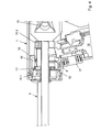
Figur 4 einen teilweise dargestellten Längsschnitt durch ein Handmodul mit eingesetztem Schneidrohr; -
Figur 5 einen teilweise dargestellten Längsschnitt durch ein Ausführungsbeispiel eines distalen Endes eines Schneidrohres; -
Figur 6 einen teilweise dargestellten Längsschnitt durch ein weiteres Ausführungsbeispiel eines distalen Endbereichs eine Schneidrohres; -
Figur 7 einen teilweise dargestellten Längsschnitt durch ein weiteres Ausführungsbeispiel eines distalen Endbereichs eine Schneidrohres. - Gemäss
Figur 1 weist ein erfindungsgemässes medizinisches Instrument R ein Handmodul 1 auf, welches aus einem Griffteil 2 und einem Führungsteil 3 besteht. In ein offenes Ende des Führungsteils 3 ist ein Ventilmodul 4 und in das andere offene Ende ein Schneidmodul 5 eingesetzt. In dem Griffteil 2 befindet sich ein inFigur 4 gezeigter Motor, auf dessen Drehachse 6 ein Kegelantriebsrad 7 aufgesetzt ist. Dieses Kegelantriebsrad 7 wirkt mit einem Ringkegelrad 8 zusammen, das ein Aufnahmeelement 9 in dem Führungsteil des Handmoduls 1 umfängt, wobei ein ringförmig ausgestalteter Rastnocken 10 in eine entsprechende Ringnut 11 in dem Aufnahmeelement 9 eingreift. Diese Ringnut 11 bildet in das Innere des Aufnahmeelements 9 wiederum eine ringförmige Rastnocke aus. - In Gebrauchslage gemäss
Figur 4 übergreift das Ringkegelrad 8 mit einem Innenzahnkranz 12 einen Aussenzahnkranz 13, der auf das als Schneidrohr ausgebildete Schneidmodul 5 aufgesetzt ist. Hierdurch wird eine Drehbewegung des Kegelantriebsrads 7 über das Ringkegelrad 8 auf den Aussenzahnkranz 13 übertragen und das Schneidmodul 5 um seine Längsachse gedreht. - Zur Abstützung des Schneidmoduls 5 bei der Drehung um seine Längsachse sind dem Schneidmodul 5 beabstandet voneinander zwei Gleitringe 14.1 und 14.2 aufgesetzt, die wiederum in einem vorderen Gleitlager 15.1 und einem hinteren Gleitlager 15.2 drehen.
- Des weiteren ist erkennbar, dass das Schneidmodul 5 über eine Rastverbindung lösbar in das Handmodul 1 bzw. das Aufnahmeelement 9 eingesetzt ist. Hierzu stehen von dem Schneidmodul 5 zwischen dem hinteren Gleitlager 15.2 und dem Aussenzahnkranz 13 Rastfedern 16 ab, die in Zusammenbaulage die nach innen als Rastnocke vorstehende Rastnut 11 hintergreifen.
- Die Funktionsweise der vorliegenden Erfindung ist folgende:
- Nach dem Einsetzen des Schneidmoduls 5 in beispielsweise einen menschlichen Körper zum Entnehmen von Gewebe, beispielsweise durch einen Trokar, wird über einen Druckknopf 17 der Motor 18 bzw. dessen Drehachse 6 in Drehbewegung versetzt. Dabei dreht auch das Kegelantriebsrad 7 und treibt über das Ringkegelrad 8, dessen Innenzahnkranz 12 und den Aussenzahnkranz 13 das Schneidmodul 5 an bzw. versetzt dieses in Drehbewegung. Dabei drehen die Gleitringe 14.1 und 14.2 in den entsprechenden Gleitlagern 15.1 und 15.2. Die Rastfedern 16 hintergreifen den in das Innere des Aufnahmeelements 9 vorspringenden ringförmigen Rastnocken. Sollte es notwendig sein, kann durch ein entsprechendes Ventil 19 in dem Ventilmodul 4 ein weiteres chirurgisches Instrument eingesetzt werden, welches dann auch durch das Schneidmodul 5 bis zu dessen distalem Ende hindurch geführt werden kann.
- Erfindungsgemäss befindet sich am distalen Ende des Schneidmoduls 5 eine Schneide bzw. ein Schneidelement 20 mit einer Schneide 21. Dieses Schneidelement 20 ist im Rahmen der vorliegenden Erfindung aus Federstahl gebildet und zu einer Hülse zusammengerollt. Gemäss
Figur 5 ist zur Aufnahme dieses Schneidelements 20 in einem entsprechenden Schneidmodul 5.1 ein innerer Einstich 22 ausgebildet, so dass das Schneidelement 20 in das Innere des Schneidmoduls 5.1 eingesetzt ist. - Gemäss
Figur 6 weist ein Schneidmodul 5.2 einen äusseren Einschnitt 23 auf, in den das Schneidelement 20 eingesetzt ist. D.h., in diesem Fall umfängt das Schneidelement 20 das distale Ende des Schneidmoduls 5.2. GemässFigur 7 schlägt das Schneidelement 20 stumpf an ein Schneidmodul 5.3 an bzw. ist an dieses Schneidmodul 5.3 stumpf angeschweisst. - Ein erfindungsgemässes Ausführungsbeispiel des medizinischen Instruments ist derart gestaltet, dass das Schneidmodul 5 ein Schneidrohr ist, an welchem distal die Schneide 21 radial umfassend bzw. umlaufend angeordnet ist. Ausserdem ist die Schneide 21 stumpf an das Schneidmodul 5.3 angesetzt. Daneben ist die Schneide 21 in einen aussen oder innen dem distalen Ende des Schneidmoduls 5.2, 5.1 eingeformten Einstich 23, 22 eingesetzt. Zuletzt ist anderenends des Schneidmoduls 5 mit dem Handmodul 1 ein Ventilmodul 4 bajonettverschlussartig verbunden.
-
1 Handmodul 34 67 2 Griffteil 35 68 3 Führungsteil 36 69 4 Ventilmodul 37 70 5 Schneidmodul 38 71 6 Drehachse 39 72 7 Kegelrad 40 73 8 Rindkegelrad 41 74 9 Aufnahmeelement 42 75 10 Rastnocke 43 76 11 Ringnut 44 77 12 Innenzahnkranz 45 78 13 Aussenzahnkranz 46 79 14 Gleitring 47 15 Gleitlager 48 16 Rastfeder 49 17 Druckknopf 50 18 Motor 51 19 Ventil 52 20 Schneidelement 53 21 Schneide 54 22 innerer Einstich 55 23 äusserer Einstich 56 24 57 R Instrument med. Instrument 25 58 26 59 27 60 28 61 29 62 30 63 31 64 32 65 33 66
Claims (15)
- Medizinisches Instrument zum Schneiden von biologischem, insbesondere menschlichem Gewebe mittels einem Schneidmodul (5) mit einer Schneide (21), welches in ein Handmodul (1) eingesetzt ist,
dadurch gekennzeichnet,
dass das Schneidmodul (5) in dem Handmodul (1) lösbar festgelegt ist. - Medizinisches Instrument nach Anspruch 1, dadurch gekennzeichnet, dass das Schneidmodul (5) ein hohles Schneidohr ist, welches um seine Drehachse drehbar mit dem Handmodul (1) verbunden ist.
- Medizinisches Instrument nach Anspruch 1 oder 2, dadurch gekennzeichnet, dass das Schneidmodul (5) eine Rastverbindung (10, 16) mit dem Handmodul (1) eingeht.
- Medizinisches Instrument nach Anspruch 3, dadurch gekennzeichnet, dass dem Schneidmodul (5) zumindest eine Raste (16) zugeordnet ist, die mit einem Rastnocken (10) in dem Handmodul (1) zusammenwirkt.
- Medizinisches Instrument nach Anspruch 4, dadurch gekennzeichnet, dass die zumindest eine Raste (16) aus dem Schneidrohr herausgeformt und selbstfedernd ausgebildet ist.
- Medizinisches Instrument nach wenigstens einem der Ansprüche 1 bis 5, dadurch gekennzeichnet, dass der Rastnocken (10) als Innenring in einem Aufnahmeelement (9) ausgebildet ist.
- Medizinisches Instrument nach wenigstens einem der Ansprüche 1 bis 6, dadurch gekennzeichnet, dass auf dem Schneidmodul (5) ein Zahnkranz (13) angeordnet ist, der mit einem Innenzahnkranz (12) in dem Handmodul (1) zusammenwirkt.
- Medizinisches Instrument nach Anspruch 7, dadurch gekennzeichnet, dass sich der Innenzahnkranz (12) an dem Aufnahmeelement (9) befindet.
- Medizinisches Instrument nach wenigstens einem der Ansprüche 1 bis 8, dadurch gekennzeichnet, dass auf dem Aufnahmeelement (9) ein Kegelrad (8) angeordnet ist, welches mit einem weiteren Kegelrad (7) zusammenwirkt, das auf einer Drehachse (6) eines Motors (18) aufgesetzt ist.
- Medizinisches Instrument nach wenigstens einem der Ansprüche 1 bis 9, dadurch gekennzeichnet, dass auf das Schneidmodul (5) zumindest ein, bevorzugt zwei beanstandete Gleitlager-Ringe (24.1, 14.2) aufgesetzt ist/sind, die mit einem bzw. zwei Gleitlagern (15.1, 15.2) in dem Handmodul (1) zusammenwirkt bzw. - wirken.
- Medizinisches Instrument zum Schneiden von biologischem, insbesondere menschlichem Gewebe mittels einem Schneidmodul (5) mit einer Schneide (21), welches in ein Handmodul (1) eingesetzt ist, dadurch gekennzeichnet, dass in dem Handmodul (1) zumindest ein Gleitlager (15.1, 15.2) vorgesehen ist, das auf Gleitringen (14.1, 14.2) auf dem Schneidmodul (5) mit einem definierten Reibmoment von mindestens 0,2 Nm jedoch maximal von 5 Nm angeordnet ist.
- Medizinisches Instrument nach Anspruch 11, dadurch gekennzeichnet, dass die Gleitlager-Ringe (14.1, 14.2) kraftschlüssig auf das Schneidmodul (5) aufgepresst sind.
- Medizinisches Instrument nach Anspruch 11 oder 12, dadurch gekennzeichnet, dass ein Aufnahmeelement (9) in dem Handmodul (1) eine Rastverbindung mit dem Schneidmodul (5) eingeht.
- Medizinisches Instrument nach wenigstens einem der Ansprüche 11 bis 13, dadurch gekennzeichnet, dass das Schneidmodul (5) aus Kunststoff geformt ist, der sich durch Dampfsterilisation selbst zerstört.
- Medizinisches Instrument zum Schneiden von biologischem, insbesondere menschlichem Gewebe mittels einem Schneidmodul (5) mit einer Schneide (21), welches in ein Handmodul (1) eingesetzt ist, dadurch gekennzeichnet, dass die Schneide (21) aus gehärtetem Flachstahl besteht und distal an dem Schneidmodul (5) angeordnet ist.
Applications Claiming Priority (1)
| Application Number | Priority Date | Filing Date | Title |
|---|---|---|---|
| DE102010037974A DE102010037974A1 (de) | 2010-10-05 | 2010-10-05 | Medizinisches Instrument |
Publications (3)
| Publication Number | Publication Date |
|---|---|
| EP2438867A2 true EP2438867A2 (de) | 2012-04-11 |
| EP2438867A3 EP2438867A3 (de) | 2012-05-02 |
| EP2438867B1 EP2438867B1 (de) | 2017-01-11 |
Family
ID=44759377
Family Applications (1)
| Application Number | Title | Priority Date | Filing Date |
|---|---|---|---|
| EP11008013.2A Not-in-force EP2438867B1 (de) | 2010-10-05 | 2011-10-04 | Medizinisches Instrument |
Country Status (3)
| Country | Link |
|---|---|
| US (1) | US9144432B2 (de) |
| EP (1) | EP2438867B1 (de) |
| DE (1) | DE102010037974A1 (de) |
Cited By (1)
| Publication number | Priority date | Publication date | Assignee | Title |
|---|---|---|---|---|
| EP3024400A4 (de) * | 2013-07-25 | 2017-03-01 | Cardiovascular Systems, Inc. | Rotierende atherektomievorrichtung mit auswechselbarer antriebswelle und zahnrädern |
Families Citing this family (11)
| Publication number | Priority date | Publication date | Assignee | Title |
|---|---|---|---|---|
| CN103860238B (zh) * | 2012-12-10 | 2016-05-04 | 财团法人金属工业研究发展中心 | 肌瘤切除装置 |
| DE202013102186U1 (de) | 2013-05-17 | 2013-06-06 | Trokamed Gmbh | Konnektierung für einen Morcellator |
| US10327795B2 (en) | 2013-05-17 | 2019-06-25 | Trokamed Gmbh | Connection for a morcellator |
| US9907566B2 (en) | 2013-07-25 | 2018-03-06 | Cardiovascualar Systems, Inc. | Rotational atherectomy device with exchangeable drive shaft and meshing gears |
| US9750526B2 (en) | 2013-07-25 | 2017-09-05 | Cardiovascular Systems, Inc. | Rotational atherectomy device with exchangeable drive shaft and meshing gears |
| US9724123B2 (en) | 2013-07-25 | 2017-08-08 | Cardiovascular Systems, Inc. | Rotational atherectomy device with exchangeable drive shaft and meshing gears |
| US9883887B2 (en) | 2013-07-25 | 2018-02-06 | Cardiovascular Systems, Inc. | Rotational atherectomy device with exchangeable drive shaft and meshing gears |
| CN106794027A (zh) * | 2014-10-14 | 2017-05-31 | 心血管系统股份有限公司 | 具有可更换驱动轴与啮合齿轮的旋切装置 |
| CA2966301A1 (en) * | 2014-11-07 | 2016-05-12 | Cardiovascular Systems, Inc. | Rotational atherectomy device with exchangeable drive shaft and meshing gears |
| US10052128B2 (en) * | 2015-08-24 | 2018-08-21 | Qathax, LLC | Catheter extraction |
| WO2021131041A1 (ja) * | 2019-12-27 | 2021-07-01 | テルモ株式会社 | 医療デバイス |
Citations (1)
| Publication number | Priority date | Publication date | Assignee | Title |
|---|---|---|---|---|
| DE10358279A1 (de) | 2003-12-11 | 2005-07-14 | Karl Storz Gmbh & Co. Kg | Medizinisches Instrument zum Schneiden von biologischen und insbesondere menschlichem Gewebe |
Family Cites Families (23)
| Publication number | Priority date | Publication date | Assignee | Title |
|---|---|---|---|---|
| US4732154A (en) * | 1984-05-14 | 1988-03-22 | Surgical Systems & Instruments, Inc. | Rotary catheter system |
| US6440148B1 (en) * | 1984-05-14 | 2002-08-27 | Samuel Shiber | Stent unclogging system with stepped spiral |
| US4815462A (en) * | 1987-04-06 | 1989-03-28 | Clark Vickie J | Lipectomy device |
| US5817033A (en) * | 1994-04-11 | 1998-10-06 | Desantis; Stephen A. | Needle core biopsy device |
| US5569284A (en) * | 1994-09-23 | 1996-10-29 | United States Surgical Corporation | Morcellator |
| US5814044A (en) * | 1995-02-10 | 1998-09-29 | Enable Medical Corporation | Apparatus and method for morselating and removing tissue from a patient |
| US5913857A (en) * | 1996-08-29 | 1999-06-22 | Ethicon End0-Surgery, Inc. | Methods and devices for collection of soft tissue |
| DE19859217B4 (de) * | 1998-12-21 | 2004-01-29 | Richard Wolf Gmbh | Elektromotorischer Antrieb für ein chirurgisches Werkzeug |
| DE29901723U1 (de) * | 1999-02-02 | 2000-06-29 | Synthes AG Chur, Chur, Graubünden | Vorrichtung zur Gewinnung von Knochenspänen |
| US6527736B1 (en) * | 2000-10-23 | 2003-03-04 | Grieshaber & Co. Ag Schaffhausen | Device for use in ophthalmologic procedures |
| US7300442B2 (en) * | 2001-07-11 | 2007-11-27 | Daniel Cherfas | Method of destroying formations in a body |
| JP4938979B2 (ja) | 2002-05-31 | 2012-05-23 | ヴァイダケア、コーパレイシャン | 骨髄にアクセスする装置および方法 |
| FR2847453B1 (fr) * | 2002-11-22 | 2005-09-23 | Jean Francois Biegun | Ancillaires, notamment rape ou bloc de coupe, a usage unique, kit comportant des ancillaires et procede de fabrication |
| DE10300127A1 (de) * | 2003-01-07 | 2004-07-22 | Richard Wolf Gmbh | Chirurgisches Rohrschaftinstrument |
| KR100589118B1 (ko) * | 2003-09-03 | 2006-06-15 | 메디칸(주) | 동축상에 석션 연결관과 식염수 공급연결관을 구비한 의료용 핸드피스 |
| JP3911503B2 (ja) * | 2004-05-19 | 2007-05-09 | 株式会社ナカニシ | 医療用ハンドピース |
| US8512340B2 (en) * | 2004-07-02 | 2013-08-20 | Stryker Corporation | Torsional pineapple dissection tip |
| DE102005049021B4 (de) * | 2005-10-11 | 2008-08-21 | Richard Wolf Gmbh | Endoskop |
| US9011472B2 (en) * | 2006-01-24 | 2015-04-21 | Depuy Mitek, Llc | Surgical tool with hydrodynamic dissipation brake |
| DE202006006914U1 (de) * | 2006-04-29 | 2006-06-22 | Richard Wolf Gmbh | Medizinisches Instrument |
| DE102007008751A1 (de) * | 2007-02-22 | 2008-08-28 | Wisap Gesellschaft für wissenschaftlichen Apparatebau mbH | Vorrichtung zum Ausschneiden und Entfernen von Gewebezylindern aus einem Gewebe und deren Verwendung |
| DE102007025242B4 (de) * | 2007-05-31 | 2014-07-31 | Gebr. Brasseler Gmbh & Co. Kg | Chirurgisches Instrument |
| US9109627B2 (en) * | 2007-12-28 | 2015-08-18 | Nissan Motor Co., Ltd. | Sliding device including sliding bearing |
-
2010
- 2010-10-05 DE DE102010037974A patent/DE102010037974A1/de not_active Ceased
-
2011
- 2011-10-04 EP EP11008013.2A patent/EP2438867B1/de not_active Not-in-force
- 2011-10-04 US US13/252,326 patent/US9144432B2/en active Active
Patent Citations (1)
| Publication number | Priority date | Publication date | Assignee | Title |
|---|---|---|---|---|
| DE10358279A1 (de) | 2003-12-11 | 2005-07-14 | Karl Storz Gmbh & Co. Kg | Medizinisches Instrument zum Schneiden von biologischen und insbesondere menschlichem Gewebe |
Cited By (1)
| Publication number | Priority date | Publication date | Assignee | Title |
|---|---|---|---|---|
| EP3024400A4 (de) * | 2013-07-25 | 2017-03-01 | Cardiovascular Systems, Inc. | Rotierende atherektomievorrichtung mit auswechselbarer antriebswelle und zahnrädern |
Also Published As
| Publication number | Publication date |
|---|---|
| US9144432B2 (en) | 2015-09-29 |
| EP2438867A3 (de) | 2012-05-02 |
| DE102010037974A1 (de) | 2012-04-05 |
| US20120083815A1 (en) | 2012-04-05 |
| EP2438867B1 (de) | 2017-01-11 |
Similar Documents
| Publication | Publication Date | Title |
|---|---|---|
| EP2438867B1 (de) | Medizinisches Instrument | |
| EP1691694B1 (de) | Medizinisches instrument zum schneiden von biologischem und insbesondere menschlichem gewebe | |
| EP2954926B1 (de) | Handgerät zum wiederholten aufstechen einer menschlichen oder einer tierischen haut | |
| DE3630210C2 (de) | ||
| DE60314109T2 (de) | Gerät zur mehrfachprobenentnahme | |
| EP2393435B1 (de) | Chirurgisches instrument zur lösbaren verbindung eines handstückes mit einem chirurgischen werkzeug | |
| EP2957233B1 (de) | Gelenk-biopsienadel zur entnahme von gewebeproben | |
| DE102004046383B4 (de) | Vorrichtung für Bürstwalze von Bodenpflegegeräten | |
| DE102012008970B3 (de) | Chirurgische Werkzeugeinrichtung | |
| EP2561816B1 (de) | Werkzeug für ein mikroinvasiv-chirugisches Instrument | |
| EP2510887B1 (de) | Werkzeug für ein mikroinvasives-chirurgisches Instrument | |
| EP3586783A2 (de) | Trokarhalterung | |
| EP2462979B1 (de) | Vorrichtung zum wiederholten Aufstechen von Haut und Stechmodul | |
| DE102011016518B4 (de) | Medizinisches oder Zahnmedizinisches Handteil | |
| EP2954927A1 (de) | Antriebsmodul für ein handgerät zum wiederholten aufstechen einer menschlichen oder tierischen haut, handgerät und verfahren | |
| EP2996586B1 (de) | Konnektierung für einen morcellator | |
| DE202013102186U1 (de) | Konnektierung für einen Morcellator | |
| DE102011050193A1 (de) | Chirurgisches Instrument, chirurgisches Handstück und chirurgisches Antriebssystem | |
| DE102013202503A1 (de) | Instrument, insbesondere medizinisch-endoskopisches Instrument oder Technoskop | |
| EP2563223B1 (de) | Stechhilfe mit automatischer auslösung | |
| US20110066154A1 (en) | Surgical File Instrument Construction with Mechanism to Convert Rotary Motion to Reciprocal Motion | |
| EP2702950B1 (de) | Medizinisches Werkzeugsystem, sowie Handgriff und Werkzeug für ein medizinisches Werkzeugsystem | |
| EP2123233A1 (de) | Fluidbetriebenes medizinisches, insbesondere dentales, Handgriffelement | |
| DE102022107970A1 (de) | Flexibles chirurgisches Werkzeug mit integrierter Lagerbaugruppe | |
| DE202018100639U1 (de) | Mikronadelvorrichtung |
Legal Events
| Date | Code | Title | Description |
|---|---|---|---|
| PUAL | Search report despatched |
Free format text: ORIGINAL CODE: 0009013 |
|
| AK | Designated contracting states |
Kind code of ref document: A2 Designated state(s): AL AT BE BG CH CY CZ DE DK EE ES FI FR GB GR HR HU IE IS IT LI LT LU LV MC MK MT NL NO PL PT RO RS SE SI SK SM TR |
|
| AX | Request for extension of the european patent |
Extension state: BA ME |
|
| PUAI | Public reference made under article 153(3) epc to a published international application that has entered the european phase |
Free format text: ORIGINAL CODE: 0009012 |
|
| AK | Designated contracting states |
Kind code of ref document: A3 Designated state(s): AL AT BE BG CH CY CZ DE DK EE ES FI FR GB GR HR HU IE IS IT LI LT LU LV MC MK MT NL NO PL PT RO RS SE SI SK SM TR |
|
| AX | Request for extension of the european patent |
Extension state: BA ME |
|
| RIC1 | Information provided on ipc code assigned before grant |
Ipc: A61B 17/32 20060101AFI20120329BHEP Ipc: A61B 17/3205 20060101ALI20120329BHEP |
|
| 17P | Request for examination filed |
Effective date: 20121102 |
|
| GRAP | Despatch of communication of intention to grant a patent |
Free format text: ORIGINAL CODE: EPIDOSNIGR1 |
|
| INTG | Intention to grant announced |
Effective date: 20160802 |
|
| GRAS | Grant fee paid |
Free format text: ORIGINAL CODE: EPIDOSNIGR3 |
|
| GRAA | (expected) grant |
Free format text: ORIGINAL CODE: 0009210 |
|
| AK | Designated contracting states |
Kind code of ref document: B1 Designated state(s): AL AT BE BG CH CY CZ DE DK EE ES FI FR GB GR HR HU IE IS IT LI LT LU LV MC MK MT NL NO PL PT RO RS SE SI SK SM TR |
|
| REG | Reference to a national code |
Ref country code: GB Ref legal event code: FG4D Free format text: NOT ENGLISH |
|
| REG | Reference to a national code |
Ref country code: CH Ref legal event code: EP |
|
| REG | Reference to a national code |
Ref country code: AT Ref legal event code: REF Ref document number: 860526 Country of ref document: AT Kind code of ref document: T Effective date: 20170115 |
|
| REG | Reference to a national code |
Ref country code: IE Ref legal event code: FG4D Free format text: LANGUAGE OF EP DOCUMENT: GERMAN |
|
| REG | Reference to a national code |
Ref country code: DE Ref legal event code: R096 Ref document number: 502011011488 Country of ref document: DE |
|
| REG | Reference to a national code |
Ref country code: NL Ref legal event code: FP |
|
| REG | Reference to a national code |
Ref country code: LT Ref legal event code: MG4D |
|
| PG25 | Lapsed in a contracting state [announced via postgrant information from national office to epo] |
Ref country code: GR Free format text: LAPSE BECAUSE OF FAILURE TO SUBMIT A TRANSLATION OF THE DESCRIPTION OR TO PAY THE FEE WITHIN THE PRESCRIBED TIME-LIMIT Effective date: 20170412 Ref country code: FI Free format text: LAPSE BECAUSE OF FAILURE TO SUBMIT A TRANSLATION OF THE DESCRIPTION OR TO PAY THE FEE WITHIN THE PRESCRIBED TIME-LIMIT Effective date: 20170111 Ref country code: LT Free format text: LAPSE BECAUSE OF FAILURE TO SUBMIT A TRANSLATION OF THE DESCRIPTION OR TO PAY THE FEE WITHIN THE PRESCRIBED TIME-LIMIT Effective date: 20170111 Ref country code: IS Free format text: LAPSE BECAUSE OF FAILURE TO SUBMIT A TRANSLATION OF THE DESCRIPTION OR TO PAY THE FEE WITHIN THE PRESCRIBED TIME-LIMIT Effective date: 20170511 Ref country code: HR Free format text: LAPSE BECAUSE OF FAILURE TO SUBMIT A TRANSLATION OF THE DESCRIPTION OR TO PAY THE FEE WITHIN THE PRESCRIBED TIME-LIMIT Effective date: 20170111 Ref country code: NO Free format text: LAPSE BECAUSE OF FAILURE TO SUBMIT A TRANSLATION OF THE DESCRIPTION OR TO PAY THE FEE WITHIN THE PRESCRIBED TIME-LIMIT Effective date: 20170411 |
|
| PG25 | Lapsed in a contracting state [announced via postgrant information from national office to epo] |
Ref country code: PT Free format text: LAPSE BECAUSE OF FAILURE TO SUBMIT A TRANSLATION OF THE DESCRIPTION OR TO PAY THE FEE WITHIN THE PRESCRIBED TIME-LIMIT Effective date: 20170511 Ref country code: PL Free format text: LAPSE BECAUSE OF FAILURE TO SUBMIT A TRANSLATION OF THE DESCRIPTION OR TO PAY THE FEE WITHIN THE PRESCRIBED TIME-LIMIT Effective date: 20170111 Ref country code: ES Free format text: LAPSE BECAUSE OF FAILURE TO SUBMIT A TRANSLATION OF THE DESCRIPTION OR TO PAY THE FEE WITHIN THE PRESCRIBED TIME-LIMIT Effective date: 20170111 Ref country code: RS Free format text: LAPSE BECAUSE OF FAILURE TO SUBMIT A TRANSLATION OF THE DESCRIPTION OR TO PAY THE FEE WITHIN THE PRESCRIBED TIME-LIMIT Effective date: 20170111 Ref country code: BG Free format text: LAPSE BECAUSE OF FAILURE TO SUBMIT A TRANSLATION OF THE DESCRIPTION OR TO PAY THE FEE WITHIN THE PRESCRIBED TIME-LIMIT Effective date: 20170411 Ref country code: LV Free format text: LAPSE BECAUSE OF FAILURE TO SUBMIT A TRANSLATION OF THE DESCRIPTION OR TO PAY THE FEE WITHIN THE PRESCRIBED TIME-LIMIT Effective date: 20170111 Ref country code: SE Free format text: LAPSE BECAUSE OF FAILURE TO SUBMIT A TRANSLATION OF THE DESCRIPTION OR TO PAY THE FEE WITHIN THE PRESCRIBED TIME-LIMIT Effective date: 20170111 |
|
| REG | Reference to a national code |
Ref country code: DE Ref legal event code: R097 Ref document number: 502011011488 Country of ref document: DE |
|
| PG25 | Lapsed in a contracting state [announced via postgrant information from national office to epo] |
Ref country code: CZ Free format text: LAPSE BECAUSE OF FAILURE TO SUBMIT A TRANSLATION OF THE DESCRIPTION OR TO PAY THE FEE WITHIN THE PRESCRIBED TIME-LIMIT Effective date: 20170111 Ref country code: RO Free format text: LAPSE BECAUSE OF FAILURE TO SUBMIT A TRANSLATION OF THE DESCRIPTION OR TO PAY THE FEE WITHIN THE PRESCRIBED TIME-LIMIT Effective date: 20170111 Ref country code: EE Free format text: LAPSE BECAUSE OF FAILURE TO SUBMIT A TRANSLATION OF THE DESCRIPTION OR TO PAY THE FEE WITHIN THE PRESCRIBED TIME-LIMIT Effective date: 20170111 Ref country code: SK Free format text: LAPSE BECAUSE OF FAILURE TO SUBMIT A TRANSLATION OF THE DESCRIPTION OR TO PAY THE FEE WITHIN THE PRESCRIBED TIME-LIMIT Effective date: 20170111 Ref country code: IT Free format text: LAPSE BECAUSE OF FAILURE TO SUBMIT A TRANSLATION OF THE DESCRIPTION OR TO PAY THE FEE WITHIN THE PRESCRIBED TIME-LIMIT Effective date: 20170111 |
|
| REG | Reference to a national code |
Ref country code: FR Ref legal event code: PLFP Year of fee payment: 7 |
|
| PLBE | No opposition filed within time limit |
Free format text: ORIGINAL CODE: 0009261 |
|
| STAA | Information on the status of an ep patent application or granted ep patent |
Free format text: STATUS: NO OPPOSITION FILED WITHIN TIME LIMIT |
|
| PG25 | Lapsed in a contracting state [announced via postgrant information from national office to epo] |
Ref country code: SM Free format text: LAPSE BECAUSE OF FAILURE TO SUBMIT A TRANSLATION OF THE DESCRIPTION OR TO PAY THE FEE WITHIN THE PRESCRIBED TIME-LIMIT Effective date: 20170111 Ref country code: DK Free format text: LAPSE BECAUSE OF FAILURE TO SUBMIT A TRANSLATION OF THE DESCRIPTION OR TO PAY THE FEE WITHIN THE PRESCRIBED TIME-LIMIT Effective date: 20170111 |
|
| 26N | No opposition filed |
Effective date: 20171012 |
|
| PG25 | Lapsed in a contracting state [announced via postgrant information from national office to epo] |
Ref country code: SI Free format text: LAPSE BECAUSE OF FAILURE TO SUBMIT A TRANSLATION OF THE DESCRIPTION OR TO PAY THE FEE WITHIN THE PRESCRIBED TIME-LIMIT Effective date: 20170111 |
|
| PG25 | Lapsed in a contracting state [announced via postgrant information from national office to epo] |
Ref country code: MC Free format text: LAPSE BECAUSE OF FAILURE TO SUBMIT A TRANSLATION OF THE DESCRIPTION OR TO PAY THE FEE WITHIN THE PRESCRIBED TIME-LIMIT Effective date: 20170111 |
|
| REG | Reference to a national code |
Ref country code: CH Ref legal event code: PL |
|
| REG | Reference to a national code |
Ref country code: IE Ref legal event code: MM4A |
|
| PG25 | Lapsed in a contracting state [announced via postgrant information from national office to epo] |
Ref country code: LI Free format text: LAPSE BECAUSE OF NON-PAYMENT OF DUE FEES Effective date: 20171031 Ref country code: CH Free format text: LAPSE BECAUSE OF NON-PAYMENT OF DUE FEES Effective date: 20171031 Ref country code: LU Free format text: LAPSE BECAUSE OF NON-PAYMENT OF DUE FEES Effective date: 20171004 |
|
| REG | Reference to a national code |
Ref country code: BE Ref legal event code: MM Effective date: 20171031 |
|
| PG25 | Lapsed in a contracting state [announced via postgrant information from national office to epo] |
Ref country code: BE Free format text: LAPSE BECAUSE OF NON-PAYMENT OF DUE FEES Effective date: 20171031 |
|
| PG25 | Lapsed in a contracting state [announced via postgrant information from national office to epo] |
Ref country code: MT Free format text: LAPSE BECAUSE OF FAILURE TO SUBMIT A TRANSLATION OF THE DESCRIPTION OR TO PAY THE FEE WITHIN THE PRESCRIBED TIME-LIMIT Effective date: 20170111 |
|
| REG | Reference to a national code |
Ref country code: FR Ref legal event code: PLFP Year of fee payment: 8 |
|
| PG25 | Lapsed in a contracting state [announced via postgrant information from national office to epo] |
Ref country code: IE Free format text: LAPSE BECAUSE OF NON-PAYMENT OF DUE FEES Effective date: 20171004 |
|
| REG | Reference to a national code |
Ref country code: AT Ref legal event code: MM01 Ref document number: 860526 Country of ref document: AT Kind code of ref document: T Effective date: 20171004 |
|
| PG25 | Lapsed in a contracting state [announced via postgrant information from national office to epo] |
Ref country code: AT Free format text: LAPSE BECAUSE OF NON-PAYMENT OF DUE FEES Effective date: 20171004 |
|
| PG25 | Lapsed in a contracting state [announced via postgrant information from national office to epo] |
Ref country code: HU Free format text: LAPSE BECAUSE OF FAILURE TO SUBMIT A TRANSLATION OF THE DESCRIPTION OR TO PAY THE FEE WITHIN THE PRESCRIBED TIME-LIMIT; INVALID AB INITIO Effective date: 20111004 |
|
| PG25 | Lapsed in a contracting state [announced via postgrant information from national office to epo] |
Ref country code: CY Free format text: LAPSE BECAUSE OF NON-PAYMENT OF DUE FEES Effective date: 20170111 |
|
| PG25 | Lapsed in a contracting state [announced via postgrant information from national office to epo] |
Ref country code: MK Free format text: LAPSE BECAUSE OF FAILURE TO SUBMIT A TRANSLATION OF THE DESCRIPTION OR TO PAY THE FEE WITHIN THE PRESCRIBED TIME-LIMIT Effective date: 20170111 |
|
| PG25 | Lapsed in a contracting state [announced via postgrant information from national office to epo] |
Ref country code: TR Free format text: LAPSE BECAUSE OF FAILURE TO SUBMIT A TRANSLATION OF THE DESCRIPTION OR TO PAY THE FEE WITHIN THE PRESCRIBED TIME-LIMIT Effective date: 20170111 |
|
| PG25 | Lapsed in a contracting state [announced via postgrant information from national office to epo] |
Ref country code: AL Free format text: LAPSE BECAUSE OF FAILURE TO SUBMIT A TRANSLATION OF THE DESCRIPTION OR TO PAY THE FEE WITHIN THE PRESCRIBED TIME-LIMIT Effective date: 20170111 |
|
| PGFP | Annual fee paid to national office [announced via postgrant information from national office to epo] |
Ref country code: NL Payment date: 20221025 Year of fee payment: 12 Ref country code: FR Payment date: 20221020 Year of fee payment: 12 |
|
| PGFP | Annual fee paid to national office [announced via postgrant information from national office to epo] |
Ref country code: GB Payment date: 20221024 Year of fee payment: 12 |
|
| P01 | Opt-out of the competence of the unified patent court (upc) registered |
Effective date: 20230602 |
|
| PGFP | Annual fee paid to national office [announced via postgrant information from national office to epo] |
Ref country code: DE Payment date: 20231218 Year of fee payment: 13 |
|
| REG | Reference to a national code |
Ref country code: NL Ref legal event code: MM Effective date: 20231101 |
|
| GBPC | Gb: european patent ceased through non-payment of renewal fee |
Effective date: 20231004 |
|
| PG25 | Lapsed in a contracting state [announced via postgrant information from national office to epo] |
Ref country code: GB Free format text: LAPSE BECAUSE OF NON-PAYMENT OF DUE FEES Effective date: 20231004 |
|
| PG25 | Lapsed in a contracting state [announced via postgrant information from national office to epo] |
Ref country code: NL Free format text: LAPSE BECAUSE OF NON-PAYMENT OF DUE FEES Effective date: 20231101 |
|
| PG25 | Lapsed in a contracting state [announced via postgrant information from national office to epo] |
Ref country code: NL Free format text: LAPSE BECAUSE OF NON-PAYMENT OF DUE FEES Effective date: 20231101 Ref country code: GB Free format text: LAPSE BECAUSE OF NON-PAYMENT OF DUE FEES Effective date: 20231004 Ref country code: FR Free format text: LAPSE BECAUSE OF NON-PAYMENT OF DUE FEES Effective date: 20231031 |
|
| REG | Reference to a national code |
Ref country code: DE Ref legal event code: R119 Ref document number: 502011011488 Country of ref document: DE |
|
| PG25 | Lapsed in a contracting state [announced via postgrant information from national office to epo] |
Ref country code: DE Free format text: LAPSE BECAUSE OF NON-PAYMENT OF DUE FEES Effective date: 20250501 |