EP2437895B2 - Umluftspritzkabine - Google Patents
Umluftspritzkabine Download PDFInfo
- Publication number
- EP2437895B2 EP2437895B2 EP11719560.2A EP11719560A EP2437895B2 EP 2437895 B2 EP2437895 B2 EP 2437895B2 EP 11719560 A EP11719560 A EP 11719560A EP 2437895 B2 EP2437895 B2 EP 2437895B2
- Authority
- EP
- European Patent Office
- Prior art keywords
- air
- spray booth
- mode
- recycled
- fan
- Prior art date
- Legal status (The legal status is an assumption and is not a legal conclusion. Google has not performed a legal analysis and makes no representation as to the accuracy of the status listed.)
- Active
Links
Images
Classifications
-
- B—PERFORMING OPERATIONS; TRANSPORTING
- B05—SPRAYING OR ATOMISING IN GENERAL; APPLYING FLUENT MATERIALS TO SURFACES, IN GENERAL
- B05B—SPRAYING APPARATUS; ATOMISING APPARATUS; NOZZLES
- B05B16/00—Spray booths
- B05B16/60—Ventilation arrangements specially adapted therefor
-
- B—PERFORMING OPERATIONS; TRANSPORTING
- B05—SPRAYING OR ATOMISING IN GENERAL; APPLYING FLUENT MATERIALS TO SURFACES, IN GENERAL
- B05B—SPRAYING APPARATUS; ATOMISING APPARATUS; NOZZLES
- B05B14/00—Arrangements for collecting, re-using or eliminating excess spraying material
- B05B14/40—Arrangements for collecting, re-using or eliminating excess spraying material for use in spray booths
- B05B14/41—Arrangements for collecting, re-using or eliminating excess spraying material for use in spray booths by cleaning the walls of the booth
-
- B—PERFORMING OPERATIONS; TRANSPORTING
- B05—SPRAYING OR ATOMISING IN GENERAL; APPLYING FLUENT MATERIALS TO SURFACES, IN GENERAL
- B05B—SPRAYING APPARATUS; ATOMISING APPARATUS; NOZZLES
- B05B14/00—Arrangements for collecting, re-using or eliminating excess spraying material
- B05B14/40—Arrangements for collecting, re-using or eliminating excess spraying material for use in spray booths
- B05B14/46—Arrangements for collecting, re-using or eliminating excess spraying material for use in spray booths by washing the air charged with excess material
- B05B14/468—Arrangements for collecting, re-using or eliminating excess spraying material for use in spray booths by washing the air charged with excess material with scrubbing means arranged below the booth floor
Definitions
- the invention relates to a circulating air spray booth with a work area for coating workpieces, with an extraction zone from which pollutant-containing, in particular solvent-containing, exhaust air is extracted, and with a fan for air circulation, the exhaust air from the spray booth in circulating air operation in the working area at least partially via at least one filter unit can be supplied again as recycled air.
- Such spray booths are known as circulating air booths.
- coating is preferably understood to mean spray painting.
- the solvent concentration (measured in g / m 3 ) increases over time.
- the concentration of the solvents should, however, not exceed 5 g / m 3 because of explosion safety.
- the increase in the solvent concentration due to the recirculation mode does not play a special role as long as the permissible limit values are not exceeded.
- the maximum solvent concentration of 5 g / m 3 permitted for exhaust air is too high, especially when large spray booths are involved, such as those used in the automotive industry.
- the solvent concentration will, however, only decrease very slowly. It usually takes about 30 to 60 minutes to lower the solvent concentration, starting from, for example, a maximum permissible value of 5.0 g / m 3 to an acceptable value of, for example, 0.01 g / m 3 .
- a spray booth according to the preamble of claim 1 is known, which is divided into several zones, in a central working area in which a higher air flow rate is required because of the spray application, and in a side area in which a lower air flow rate is required.
- the spray booth can at least partially be operated in recirculation mode, which means that part of the less polluted air from the side area is processed again and fed as additional air into the application area in order to increase the air throughput here.
- the air throughput of recycled air and fresh air can be designed variably and controlled automatically.
- a circulating air spray booth according to the preamble of claim 1 is known, in which a switch is provided between a circulating air mode for painting and a quick venting mode for quick venting when the spray booth is to be entered. If you want to enter the spray booth, you can switch to quick ventilation mode. The air circulation mode is then ended and a vent is opened so that the solvent concentration inside the spray booth drops to a level that is permissible for entry.
- the invention is based on the object of creating a circulating air spray booth which, when the spraying operation is interrupted, enables the solvent concentration to be rapidly reduced to a permissible value for entering the spray booth. Furthermore, the most energy-saving operation of the spray booth should be ensured.
- the spray booth can be switched to a quick ventilation mode and in which at least partially non-recycled, preferably filtered, supply air is supplied to the work area, the solvent-containing air present in the work area is exchanged more quickly and the solvent concentration is reduced to permissible values more quickly.
- a harmless solvent concentration is achieved after a short time after switching to quick exhaust operation, so that a worker can enter the spray booth without additional protective measures such as breathing masks.
- part of the exhaust air is fed back into the spray booth via a filter unit as recycled supply air and part of the exhaust air is released to the environment via the roof or an exhaust air purification system.
- the exhaust air released into the environment is previously treated, preferably washed, filtered and / or thermally post-treated or air-conditioned.
- the prescribed limit values are complied with or a further reduction in the pollutant concentration can be achieved by means of thermal post-treatment (thermal post-combustion).
- the spray booth can gradually be switched between a circulating air mode and a quick ventilation mode or vice versa.
- air valve is understood to mean a valve of some kind for regulating air. In the simplest case, this is a variable flap with a servomotor.
- the controllable fan usually has a frequency converter for low-loss control.
- the spray booth comprises a conveyor for conveying workpieces through the spray booth via an entrance through the work area and an exit, at least one separate area being provided at the entrance and preferably at the exit of the spray booth, the connections for separate connections from the work area Has supply and exhaust air, each separated area being able to be subjected to an overpressure with respect to the environment.
- At least one fan is preferably provided for the work area and at least one fan for each separated area, with non-recycled, filtered air being able to be supplied to the work area in the quick ventilation mode.
- the work area is also freed of solvents by supplying non-recycled, filtered air. This is particularly important in the case of spray booths with a long design, in order to ensure sufficiently rapid ventilation.
- the air supplied to the work area in quick ventilation mode can be branched off from at least one separated area.
- only non-recycled, filtered air is fed in, at least in the separated area at the entrance.
- air sucked out of the work area in quick ventilation mode is preferably not recycled, but is discharged as exhaust air.
- At least one wet scrubber or suction device is provided, via which e.g. exhaust air is extracted at the bottom.
- the spray booth is basically constructed in a known manner according to the state of the art, whereby the spray booth can also have several water-flooded trickle walls, which finally open into a common receptacle, through which exhaust air can be sucked off at the bottom, for example a venturi washer or the like can act.
- Such wet scrubbers or suction devices are preferably provided in each sub-area of the spray booth.
- the fan for the work area is operated in quick ventilation mode with a reduced output such that an overpressure is maintained in the area of the filter ceiling (plenum).
- the fan power of the working area is preferably gradually reduced and filtered air that is not recycled is gradually supplied from a separate area.
- the fan output of the work area is preferably gradually increased and non-recycled, filtered air supplied from a separated area is gradually diverted back into the separated area.
- the working area is preferably continuously supplied with air via a filter unit, that is to say both during circulating air operation and during quick ventilation operation.
- the filter ceiling (the plenum) is constantly under a certain overpressure, so that no dust detachment and the like occur.
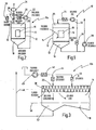
- a circulating air spray booth is shown in simplified form and denoted as a whole by the number 10.
- the circulating air spray booth 10 has a closed housing 12 in which a work area 14 for spray painting workpieces 16 is located.
- a wet scrubber 18 is provided below a floor 13, through which exhaust air is sucked off on the floor side.
- air is fed in at 90,000 m 3 / h via a fan 22 via one or more filters 24 and fed into the work area 14 from above via a filter ceiling 20 (also known as plenum).
- a part of the exhaust air sucked off via the wet scrubber 18 is sucked off via a further fan 28 and released to the outside, for example via the roof.
- Fig. 2 is a slightly modified version of the spray booth according to Fig. 1 shown and designated as a whole by numeral 10a.
- the working area 14 is supplied with circulating air via a fan 22 in circulating air mode via a filter 24 and a valve 32.
- the fan 22 has an output of 100,000 m 3 / h in recirculation mode. While 90,000 m 3 / h are passed into the working area 14 as recycled, filtered air, 10,000 m 3 / h are fed via a valve 32 to a thermal post-combustion 34, where it is thermally post-burned and finally released into the open.
- the thermal afterburning can preferably also be a regenerative thermal afterburning RNV.
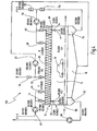
- FIG. 3 Another embodiment of a circulating air spray booth according to the invention is shown and denoted as a whole by number 10b.
- This is a larger spray booth, such as that used for painting vehicles in the automotive industry.
- the spray booth 10b has an elongated working area 14, which is only partially shown here, upstream of which an entrance area 38 (separate area at the entrance) is connected.
- a conveyor 50 runs through the spray booth 10b, by means of which workpieces 16 are moved continuously or cyclically over the input area 38 through the work area 14.
- the work area 14 has its own air duct, which is shown here in Fig. 3 is not shown.
- a fan 40 is provided for the entrance area 38, by means of which fresh air is sucked in from the outside and is fed into the entrance area 38 from above via a filter 42 and a valve 44 via the plenum 20.
- This is, for example, 50,000 m 3 / h.
- a part, namely 20,000 m 3 / h, passes through a suction area 52 of the entrance area 38 and is finally released to the environment via a line 48.
- 25,000 m 3 / h are diverted to work area 14.
- the remaining 5,000 m 3 / h are released into the environment as "overpressure".
- the spray booth 10b is therefore completely under excess pressure, so that no dust, foreign particles, etc.
- the second part of 25,000 m 3 / h is supplied to the work area 14 via a further air valve 46. With the aid of this air flow, effective ventilation of the work area 14 is ensured, so that effective ventilation takes place even with very long work areas 14. In the quick ventilation mode, there is no further diversion of air from the entrance area 38 to the work area 14.
- Fig. 4 is based on the previously based on Fig. 3
- the illustrated embodiment now shows a complete version of a spray booth 10c for vehicle painting in the automotive sector.
- the spray booth 10c has an elongated housing 12, with a work area 14, an entrance area 38 and an exit area 66. Again, workpieces 16 are guided by means of a conveyor 50 through the entrance area 38, the work area 14 and the exit area 66 of the spray booth 10c.
- the work area 14 as well as the entrance area 38 and the exit area 36 are provided with wet scrubbers or suction devices 18 and 52 and 54, respectively. Filtered air is supplied from above via the plenum 20.
- a fan 22 with 300,000 m 3 / h is used to supply 250,000 m 3 / h via a valve 32 as recycled, filtered air via the plenum 20 from above into the work area 14.
- a total of 300,000 m 3 / h are sucked off by means of the blower 22 via a wet scrubber 18, the remaining 50,000 m 3 / h are discharged to the outside via a valve 30 or fed to a thermal post-combustion.
- a blower 40 is provided at the entrance area 38, by means of which 80,000 m 3 / h are sucked in in recirculation mode and fed into the entrance area 38 via a valve 44 via the plenum 20.
- 50,000 m 3 / h reach the outside as exhaust air via the suction device 52 and a further fan 28. Another 25,000 m 3 / h are diverted to work area 14. The remaining 5,000 m 3 / h escape to the outside as overpressure at the entrance.
- a further blower 56 with 80,000 m 3 / h is provided in the exit area 66. These 80,000 m 3 / h are passed through a valve 60 from above via the plenum 20 into the outlet area 66. Of this, 50,000 m 3 / h reach the blower 56 via the suction device 54 and a valve 64. A further 30,000 m 3 / h are drawn in as fresh air via a valve 62 from the outside via the blower 56.
- a further portion of 25,000 m 3 / h of the air flow of 80,000 m 3 / h supplied via the valve 60 is diverted into the working area 14.
- the remaining portion of 5,000 m 3 / h escapes to the outside from the exit area 66, so that no ingress of dust and the like is possible here either.
- the two fans 40, 56 continue to run with the same output of 80,000 m 3 / h.
- the fan 22 is reduced to an output of 50,000 m 3 / h.
- These 50,000 m 3 / h continue to be discharged to the outside via the valve 30 or passed to thermal post-combustion.
- the valve 32 is closed so that no more recycled air can get into the working area 14.
- the valve position of the valve 44 is changed in such a way that only 55,000 m 3 / h reach the inlet area 38 via this valve 44.
- the remaining portion of 25,000 m 3 / h is fed via a valve 46 into the working area 14 via the plenum 20.
- the air flow of 55,000 m 3 / h in the entrance area 38 reaches the outside at 50,000 m 3 / h via the suction device 52 and the fan 28 as exhaust air, while 5,000 m 3 / h escape at the entrance as overpressure.
- air supplied from the valve 44 is no longer diverted into the working area 14.
- a valve 58 deflects part of the air flow of 80,000 m 3 / h, namely 25,000 m 3 / h, via the plenum 20 from above into the work area 14.
- the remaining portion of 55,000 m 3 / h is led through the exit area 66, with no more diversion into the work area 14.
- 50,000 m 3 / h return to the fan 56 via the suction device 54 and the valve 64, while the remaining 5,000 m 3 / h escape as overpressure at the outlet.
- the spray booth 10c is ventilated very quickly when switching to rapid venting mode. At the same time, it is avoided that the fan 56 has to be started up again from zero, so that start-up vibrations etc. that arise as a result are avoided.
Landscapes
- Details Or Accessories Of Spraying Plant Or Apparatus (AREA)
Priority Applications (1)
| Application Number | Priority Date | Filing Date | Title |
|---|---|---|---|
| PL11719560T PL2437895T5 (pl) | 2010-05-17 | 2011-05-13 | Natryskowa kabina lakiernicza z recyrkulacją powietrza |
Applications Claiming Priority (2)
| Application Number | Priority Date | Filing Date | Title |
|---|---|---|---|
| DE102010021540A DE102010021540A1 (de) | 2010-05-17 | 2010-05-17 | Umluftspritzkabine |
| PCT/EP2011/057755 WO2011144527A1 (de) | 2010-05-17 | 2011-05-13 | Umluftspritzkabine |
Publications (3)
| Publication Number | Publication Date |
|---|---|
| EP2437895A1 EP2437895A1 (de) | 2012-04-11 |
| EP2437895B1 EP2437895B1 (de) | 2014-01-22 |
| EP2437895B2 true EP2437895B2 (de) | 2020-11-04 |
Family
ID=44170471
Family Applications (1)
| Application Number | Title | Priority Date | Filing Date |
|---|---|---|---|
| EP11719560.2A Active EP2437895B2 (de) | 2010-05-17 | 2011-05-13 | Umluftspritzkabine |
Country Status (6)
| Country | Link |
|---|---|
| EP (1) | EP2437895B2 (pl) |
| DE (1) | DE102010021540A1 (pl) |
| ES (1) | ES2445766T5 (pl) |
| PL (1) | PL2437895T5 (pl) |
| PT (1) | PT2437895E (pl) |
| WO (1) | WO2011144527A1 (pl) |
Families Citing this family (3)
| Publication number | Priority date | Publication date | Assignee | Title |
|---|---|---|---|---|
| DE202012103894U1 (de) | 2012-10-11 | 2014-01-15 | Dürr Systems GmbH | Oberflächenbehandlungsvorrichtung |
| DE102016114466A1 (de) * | 2016-08-04 | 2018-02-08 | Eisenmann Se | Konditioniervorrichtung und Verfahren zum Konditionieren eines gasförmigen Mediums sowie Anlage und Verfahren zum Behandeln von Werkstücken |
| CN110891541A (zh) | 2017-05-05 | 2020-03-17 | 巴德里·阿穆图尔 | 刺激方法和设备 |
Citations (2)
| Publication number | Priority date | Publication date | Assignee | Title |
|---|---|---|---|---|
| DE3334257C1 (de) † | 1983-09-22 | 1985-02-14 | RMG Beierling GmbH, 4791 Altenbeken | Lackier- und Abdunstanlage mit Umluftbelueftung |
| DE19941184A1 (de) † | 1999-08-30 | 2001-03-01 | Flaekt Ab | Lacktrockner und Lacktrockneranlage |
Family Cites Families (5)
| Publication number | Priority date | Publication date | Assignee | Title |
|---|---|---|---|---|
| SE454328B (sv) | 1982-04-30 | 1988-04-25 | Flaekt Ab | Forfarande och anordning for ventilering av en sprutbox |
| DE4228660A1 (de) * | 1992-08-28 | 1994-03-03 | Alfred Feige | Belüftungseinrichtung für Lackierkabinen o. dgl. |
| US5643077A (en) * | 1995-06-16 | 1997-07-01 | Ayer; Jacqueline | Continually optimized, variable flow rate ventilation system |
| ATE428508T1 (de) * | 2001-01-15 | 2009-05-15 | Bolin Heatex Technology Gmbh | Belüftungsvorrichtung für eine spritzkabine eines lackierbetriebs |
| DE102007015150A1 (de) * | 2007-03-02 | 2008-09-04 | Wurster, Gerd | Lackieranlage |
-
2010
- 2010-05-17 DE DE102010021540A patent/DE102010021540A1/de not_active Withdrawn
-
2011
- 2011-05-13 PT PT117195602T patent/PT2437895E/pt unknown
- 2011-05-13 EP EP11719560.2A patent/EP2437895B2/de active Active
- 2011-05-13 PL PL11719560T patent/PL2437895T5/pl unknown
- 2011-05-13 WO PCT/EP2011/057755 patent/WO2011144527A1/de not_active Ceased
- 2011-05-13 ES ES11719560T patent/ES2445766T5/es active Active
Patent Citations (2)
| Publication number | Priority date | Publication date | Assignee | Title |
|---|---|---|---|---|
| DE3334257C1 (de) † | 1983-09-22 | 1985-02-14 | RMG Beierling GmbH, 4791 Altenbeken | Lackier- und Abdunstanlage mit Umluftbelueftung |
| DE19941184A1 (de) † | 1999-08-30 | 2001-03-01 | Flaekt Ab | Lacktrockner und Lacktrockneranlage |
Also Published As
| Publication number | Publication date |
|---|---|
| EP2437895A1 (de) | 2012-04-11 |
| PL2437895T5 (pl) | 2021-03-08 |
| WO2011144527A1 (de) | 2011-11-24 |
| ES2445766T5 (es) | 2021-06-18 |
| DE102010021540A1 (de) | 2011-11-17 |
| ES2445766T3 (es) | 2014-03-05 |
| PL2437895T3 (pl) | 2014-06-30 |
| PT2437895E (pt) | 2014-03-27 |
| EP2437895B1 (de) | 2014-01-22 |
Similar Documents
| Publication | Publication Date | Title |
|---|---|---|
| EP0438076B1 (de) | Belüftungseinrichtung für Fahrzeugkabine | |
| EP2736655B1 (de) | Kompakte lackieranlage | |
| EP2026910B1 (de) | Lackieranlage | |
| DE2928226A1 (de) | Farbspritzanlagen fuer gegenstaende und energiesparendes verfahren zum farbspritzen | |
| WO2021063444A1 (de) | Behandlungsanlage und behandlungsverfahren | |
| EP2814619B1 (de) | Verfahren zum behandeln von gegenständen und anlage hierfür | |
| EP2244840B1 (de) | Vorrichtung und verfahren zum zuführen von luft zu einem applikationsbereich einer lackieranlage | |
| EP2437895B1 (de) | Umluftspritzkabine | |
| DE202020103567U1 (de) | Behandlungsanlage | |
| DE202011001810U1 (de) | Abluftreinigungssystem für Nutztierställe | |
| DE112016000194B4 (de) | Windkanalumlauf-Sichtvorrichtung für Schüttmaterial | |
| EP2244839B1 (de) | Lackieranlage | |
| EP3538829A1 (de) | Trockenraum | |
| DE202015105649U1 (de) | Innenraumlüftungsanlage | |
| DE102021004571A1 (de) | Verfahren zum Reinigen von bei einem Bearbeitungsprozess in einem Reinraum/Trockenraum entstehender Abluft sowie Anlage zur Durchführung des Verfahrens | |
| EP4144450B1 (de) | Verfahren zum reinigen von bei einem bearbeitungsprozess in einem reinraum/trockenraum entstehender abluft sowie anlage zur durchführung des verfahrens | |
| EP2117723B1 (de) | Verfahren und vorrichtung zum entfernen von feststoffen aus beim lackieren von gegenständen entstehendem overspray | |
| DE19912361B4 (de) | Lackieranlage | |
| EP1466880B1 (de) | Verfahren und Vorrichtung zur biologisch mechanischen Behandlung von organischem Material | |
| DE69001230T2 (de) | Fahrbare lueftungsanlage. | |
| EP4400197A1 (de) | Lufteintritts- oder luftaustrittsfilter für ein schaltschrankgehäuse und eine entsprechende schaltschrankanordnung | |
| EP0253980A1 (de) | Verfahren und Vorrichtung zum Reinigen der Abluft einer manuell betriebenen Spritzkabine | |
| DE2947334A1 (de) | Saugkasten | |
| DE102021126089B3 (de) | Verfahren zur lastabhängigen Trocknereinstellung und Trockner | |
| EP0584638A2 (de) | Belüftungseinrichtung für Lackierkabinen oder dgl. |
Legal Events
| Date | Code | Title | Description |
|---|---|---|---|
| PUAI | Public reference made under article 153(3) epc to a published international application that has entered the european phase |
Free format text: ORIGINAL CODE: 0009012 |
|
| 17P | Request for examination filed |
Effective date: 20111228 |
|
| AK | Designated contracting states |
Kind code of ref document: A1 Designated state(s): AL AT BE BG CH CY CZ DE DK EE ES FI FR GB GR HR HU IE IS IT LI LT LU LV MC MK MT NL NO PL PT RO RS SE SI SK SM TR |
|
| 17Q | First examination report despatched |
Effective date: 20121009 |
|
| GRAP | Despatch of communication of intention to grant a patent |
Free format text: ORIGINAL CODE: EPIDOSNIGR1 |
|
| DAX | Request for extension of the european patent (deleted) | ||
| INTG | Intention to grant announced |
Effective date: 20130805 |
|
| GRAS | Grant fee paid |
Free format text: ORIGINAL CODE: EPIDOSNIGR3 |
|
| GRAA | (expected) grant |
Free format text: ORIGINAL CODE: 0009210 |
|
| RAP1 | Party data changed (applicant data changed or rights of an application transferred) |
Owner name: DUERR SYSTEMS GMBH |
|
| AK | Designated contracting states |
Kind code of ref document: B1 Designated state(s): AL AT BE BG CH CY CZ DE DK EE ES FI FR GB GR HR HU IE IS IT LI LT LU LV MC MK MT NL NO PL PT RO RS SE SI SK SM TR |
|
| REG | Reference to a national code |
Ref country code: GB Ref legal event code: FG4D Free format text: NOT ENGLISH |
|
| REG | Reference to a national code |
Ref country code: CH Ref legal event code: EP |
|
| REG | Reference to a national code |
Ref country code: AT Ref legal event code: REF Ref document number: 650515 Country of ref document: AT Kind code of ref document: T Effective date: 20140215 |
|
| REG | Reference to a national code |
Ref country code: IE Ref legal event code: FG4D Free format text: LANGUAGE OF EP DOCUMENT: GERMAN |
|
| REG | Reference to a national code |
Ref country code: ES Ref legal event code: FG2A Ref document number: 2445766 Country of ref document: ES Kind code of ref document: T3 Effective date: 20140305 |
|
| REG | Reference to a national code |
Ref country code: DE Ref legal event code: R096 Ref document number: 502011002109 Country of ref document: DE Effective date: 20140306 |
|
| REG | Reference to a national code |
Ref country code: PT Ref legal event code: SC4A Free format text: AVAILABILITY OF NATIONAL TRANSLATION Effective date: 20140320 |
|
| REG | Reference to a national code |
Ref country code: RO Ref legal event code: EPE |
|
| REG | Reference to a national code |
Ref country code: NL Ref legal event code: T3 |
|
| REG | Reference to a national code |
Ref country code: LT Ref legal event code: MG4D |
|
| REG | Reference to a national code |
Ref country code: PL Ref legal event code: T3 |
|
| REG | Reference to a national code |
Ref country code: SK Ref legal event code: T3 Ref document number: E 16187 Country of ref document: SK |
|
| PG25 | Lapsed in a contracting state [announced via postgrant information from national office to epo] |
Ref country code: LT Free format text: LAPSE BECAUSE OF FAILURE TO SUBMIT A TRANSLATION OF THE DESCRIPTION OR TO PAY THE FEE WITHIN THE PRESCRIBED TIME-LIMIT Effective date: 20140122 Ref country code: IS Free format text: LAPSE BECAUSE OF FAILURE TO SUBMIT A TRANSLATION OF THE DESCRIPTION OR TO PAY THE FEE WITHIN THE PRESCRIBED TIME-LIMIT Effective date: 20140522 Ref country code: NO Free format text: LAPSE BECAUSE OF FAILURE TO SUBMIT A TRANSLATION OF THE DESCRIPTION OR TO PAY THE FEE WITHIN THE PRESCRIBED TIME-LIMIT Effective date: 20140422 |
|
| PG25 | Lapsed in a contracting state [announced via postgrant information from national office to epo] |
Ref country code: CY Free format text: LAPSE BECAUSE OF FAILURE TO SUBMIT A TRANSLATION OF THE DESCRIPTION OR TO PAY THE FEE WITHIN THE PRESCRIBED TIME-LIMIT Effective date: 20140122 Ref country code: SE Free format text: LAPSE BECAUSE OF FAILURE TO SUBMIT A TRANSLATION OF THE DESCRIPTION OR TO PAY THE FEE WITHIN THE PRESCRIBED TIME-LIMIT Effective date: 20140122 |
|
| PG25 | Lapsed in a contracting state [announced via postgrant information from national office to epo] |
Ref country code: LV Free format text: LAPSE BECAUSE OF FAILURE TO SUBMIT A TRANSLATION OF THE DESCRIPTION OR TO PAY THE FEE WITHIN THE PRESCRIBED TIME-LIMIT Effective date: 20140122 Ref country code: RS Free format text: LAPSE BECAUSE OF FAILURE TO SUBMIT A TRANSLATION OF THE DESCRIPTION OR TO PAY THE FEE WITHIN THE PRESCRIBED TIME-LIMIT Effective date: 20140122 Ref country code: HR Free format text: LAPSE BECAUSE OF FAILURE TO SUBMIT A TRANSLATION OF THE DESCRIPTION OR TO PAY THE FEE WITHIN THE PRESCRIBED TIME-LIMIT Effective date: 20140122 |
|
| REG | Reference to a national code |
Ref country code: DE Ref legal event code: R026 Ref document number: 502011002109 Country of ref document: DE |
|
| PG25 | Lapsed in a contracting state [announced via postgrant information from national office to epo] |
Ref country code: EE Free format text: LAPSE BECAUSE OF FAILURE TO SUBMIT A TRANSLATION OF THE DESCRIPTION OR TO PAY THE FEE WITHIN THE PRESCRIBED TIME-LIMIT Effective date: 20140122 Ref country code: DK Free format text: LAPSE BECAUSE OF FAILURE TO SUBMIT A TRANSLATION OF THE DESCRIPTION OR TO PAY THE FEE WITHIN THE PRESCRIBED TIME-LIMIT Effective date: 20140122 |
|
| PLBI | Opposition filed |
Free format text: ORIGINAL CODE: 0009260 |
|
| PLAX | Notice of opposition and request to file observation + time limit sent |
Free format text: ORIGINAL CODE: EPIDOSNOBS2 |
|
| 26 | Opposition filed |
Opponent name: EISENMANN SE Effective date: 20141017 |
|
| PG25 | Lapsed in a contracting state [announced via postgrant information from national office to epo] |
Ref country code: LU Free format text: LAPSE BECAUSE OF FAILURE TO SUBMIT A TRANSLATION OF THE DESCRIPTION OR TO PAY THE FEE WITHIN THE PRESCRIBED TIME-LIMIT Effective date: 20140513 |
|
| REG | Reference to a national code |
Ref country code: CH Ref legal event code: PL |
|
| REG | Reference to a national code |
Ref country code: DE Ref legal event code: R026 Ref document number: 502011002109 Country of ref document: DE Effective date: 20141017 |
|
| PG25 | Lapsed in a contracting state [announced via postgrant information from national office to epo] |
Ref country code: MC Free format text: LAPSE BECAUSE OF FAILURE TO SUBMIT A TRANSLATION OF THE DESCRIPTION OR TO PAY THE FEE WITHIN THE PRESCRIBED TIME-LIMIT Effective date: 20140122 Ref country code: LI Free format text: LAPSE BECAUSE OF NON-PAYMENT OF DUE FEES Effective date: 20140531 Ref country code: CH Free format text: LAPSE BECAUSE OF NON-PAYMENT OF DUE FEES Effective date: 20140531 |
|
| REG | Reference to a national code |
Ref country code: IE Ref legal event code: MM4A |
|
| REG | Reference to a national code |
Ref country code: HU Ref legal event code: AG4A Ref document number: E021898 Country of ref document: HU |
|
| PLAF | Information modified related to communication of a notice of opposition and request to file observations + time limit |
Free format text: ORIGINAL CODE: EPIDOSCOBS2 |
|
| PG25 | Lapsed in a contracting state [announced via postgrant information from national office to epo] |
Ref country code: IE Free format text: LAPSE BECAUSE OF NON-PAYMENT OF DUE FEES Effective date: 20140513 |
|
| PG25 | Lapsed in a contracting state [announced via postgrant information from national office to epo] |
Ref country code: SI Free format text: LAPSE BECAUSE OF FAILURE TO SUBMIT A TRANSLATION OF THE DESCRIPTION OR TO PAY THE FEE WITHIN THE PRESCRIBED TIME-LIMIT Effective date: 20140122 |
|
| PLBB | Reply of patent proprietor to notice(s) of opposition received |
Free format text: ORIGINAL CODE: EPIDOSNOBS3 |
|
| PG25 | Lapsed in a contracting state [announced via postgrant information from national office to epo] |
Ref country code: MT Free format text: LAPSE BECAUSE OF FAILURE TO SUBMIT A TRANSLATION OF THE DESCRIPTION OR TO PAY THE FEE WITHIN THE PRESCRIBED TIME-LIMIT Effective date: 20140122 |
|
| PG25 | Lapsed in a contracting state [announced via postgrant information from national office to epo] |
Ref country code: SM Free format text: LAPSE BECAUSE OF FAILURE TO SUBMIT A TRANSLATION OF THE DESCRIPTION OR TO PAY THE FEE WITHIN THE PRESCRIBED TIME-LIMIT Effective date: 20140122 |
|
| REG | Reference to a national code |
Ref country code: FR Ref legal event code: PLFP Year of fee payment: 6 |
|
| PG25 | Lapsed in a contracting state [announced via postgrant information from national office to epo] |
Ref country code: GR Free format text: LAPSE BECAUSE OF FAILURE TO SUBMIT A TRANSLATION OF THE DESCRIPTION OR TO PAY THE FEE WITHIN THE PRESCRIBED TIME-LIMIT Effective date: 20140423 Ref country code: BG Free format text: LAPSE BECAUSE OF FAILURE TO SUBMIT A TRANSLATION OF THE DESCRIPTION OR TO PAY THE FEE WITHIN THE PRESCRIBED TIME-LIMIT Effective date: 20140122 |
|
| PG25 | Lapsed in a contracting state [announced via postgrant information from national office to epo] |
Ref country code: BE Free format text: LAPSE BECAUSE OF FAILURE TO SUBMIT A TRANSLATION OF THE DESCRIPTION OR TO PAY THE FEE WITHIN THE PRESCRIBED TIME-LIMIT Effective date: 20140531 |
|
| REG | Reference to a national code |
Ref country code: DE Ref legal event code: R082 Ref document number: 502011002109 Country of ref document: DE Representative=s name: WITTE, WELLER & PARTNER PATENTANWAELTE MBB, DE Ref country code: DE Ref legal event code: R081 Ref document number: 502011002109 Country of ref document: DE Owner name: DUERR SYSTEMS AG, DE Free format text: FORMER OWNER: DUERR SYSTEMS GMBH, 74321 BIETIGHEIM-BISSINGEN, DE |
|
| RAP2 | Party data changed (patent owner data changed or rights of a patent transferred) |
Owner name: DUERR SYSTEMS AG |
|
| REG | Reference to a national code |
Ref country code: NL Ref legal event code: PD Owner name: DUERR SYSTEMS AG; DE Free format text: DETAILS ASSIGNMENT: CHANGE OF OWNER(S), CHANGE OF LEGAL ENTITY; FORMER OWNER NAME: DUERR SYSTEMS AG Effective date: 20161025 |
|
| REG | Reference to a national code |
Ref country code: FR Ref legal event code: CD Owner name: DURR SYSTEMS AG, DE Effective date: 20161026 |
|
| REG | Reference to a national code |
Ref country code: HU Ref legal event code: FH1C Free format text: FORMER REPRESENTATIVE(S): ERDELY PETER - DANUBIA SZABADALMI ES JOGI IRODA KFT., HU Representative=s name: DANUBIA SZABADALMI ES JOGI IRODA KFT., HU Ref country code: HU Ref legal event code: GB9C Owner name: DUERR SYSTEMS AG, DE Free format text: FORMER OWNER(S): DUERR SYSTEMS GMBH, DE |
|
| REG | Reference to a national code |
Ref country code: SK Ref legal event code: TC4A Ref document number: E 16187 Country of ref document: SK Owner name: DUERR SYSTEMS AG, BIETIGHEIM-BISSINGEN, DE Effective date: 20170110 |
|
| REG | Reference to a national code |
Ref country code: AT Ref legal event code: PC Ref document number: 650515 Country of ref document: AT Kind code of ref document: T Owner name: DUERR SYSTEMS AG, DE Effective date: 20161223 |
|
| APBM | Appeal reference recorded |
Free format text: ORIGINAL CODE: EPIDOSNREFNO |
|
| APBP | Date of receipt of notice of appeal recorded |
Free format text: ORIGINAL CODE: EPIDOSNNOA2O |
|
| APAH | Appeal reference modified |
Free format text: ORIGINAL CODE: EPIDOSCREFNO |
|
| REG | Reference to a national code |
Ref country code: FR Ref legal event code: PLFP Year of fee payment: 7 |
|
| APBQ | Date of receipt of statement of grounds of appeal recorded |
Free format text: ORIGINAL CODE: EPIDOSNNOA3O |
|
| PLAB | Opposition data, opponent's data or that of the opponent's representative modified |
Free format text: ORIGINAL CODE: 0009299OPPO |
|
| R26 | Opposition filed (corrected) |
Opponent name: EISENMANN SE Effective date: 20141017 |
|
| REG | Reference to a national code |
Ref country code: DE Ref legal event code: R079 Ref document number: 502011002109 Country of ref document: DE Free format text: PREVIOUS MAIN CLASS: B05B0015120000 Ipc: B05B0016000000 |
|
| REG | Reference to a national code |
Ref country code: FR Ref legal event code: PLFP Year of fee payment: 8 |
|
| PG25 | Lapsed in a contracting state [announced via postgrant information from national office to epo] |
Ref country code: MK Free format text: LAPSE BECAUSE OF FAILURE TO SUBMIT A TRANSLATION OF THE DESCRIPTION OR TO PAY THE FEE WITHIN THE PRESCRIBED TIME-LIMIT Effective date: 20140122 |
|
| PG25 | Lapsed in a contracting state [announced via postgrant information from national office to epo] |
Ref country code: AL Free format text: LAPSE BECAUSE OF FAILURE TO SUBMIT A TRANSLATION OF THE DESCRIPTION OR TO PAY THE FEE WITHIN THE PRESCRIBED TIME-LIMIT Effective date: 20140122 |
|
| APBU | Appeal procedure closed |
Free format text: ORIGINAL CODE: EPIDOSNNOA9O |
|
| PGFP | Annual fee paid to national office [announced via postgrant information from national office to epo] |
Ref country code: TR Payment date: 20200512 Year of fee payment: 10 |
|
| PUAH | Patent maintained in amended form |
Free format text: ORIGINAL CODE: 0009272 |
|
| STAA | Information on the status of an ep patent application or granted ep patent |
Free format text: STATUS: PATENT MAINTAINED AS AMENDED |
|
| 27A | Patent maintained in amended form |
Effective date: 20201104 |
|
| AK | Designated contracting states |
Kind code of ref document: B2 Designated state(s): AL AT BE BG CH CY CZ DE DK EE ES FI FR GB GR HR HU IE IS IT LI LT LU LV MC MK MT NL NO PL PT RO RS SE SI SK SM TR |
|
| REG | Reference to a national code |
Ref country code: DE Ref legal event code: R102 Ref document number: 502011002109 Country of ref document: DE |
|
| REG | Reference to a national code |
Ref country code: SK Ref legal event code: T5 Ref document number: E 16187 Country of ref document: SK |
|
| REG | Reference to a national code |
Ref country code: NL Ref legal event code: FP |
|
| REG | Reference to a national code |
Ref country code: ES Ref legal event code: DC2A Ref document number: 2445766 Country of ref document: ES Kind code of ref document: T5 Effective date: 20210618 |
|
| PGFP | Annual fee paid to national office [announced via postgrant information from national office to epo] |
Ref country code: NL Payment date: 20210519 Year of fee payment: 11 Ref country code: RO Payment date: 20210429 Year of fee payment: 11 |
|
| PGFP | Annual fee paid to national office [announced via postgrant information from national office to epo] |
Ref country code: GB Payment date: 20210525 Year of fee payment: 11 Ref country code: AT Payment date: 20210520 Year of fee payment: 11 |
|
| REG | Reference to a national code |
Ref country code: NL Ref legal event code: MM Effective date: 20220601 |
|
| REG | Reference to a national code |
Ref country code: AT Ref legal event code: MM01 Ref document number: 650515 Country of ref document: AT Kind code of ref document: T Effective date: 20220513 |
|
| GBPC | Gb: european patent ceased through non-payment of renewal fee |
Effective date: 20220513 |
|
| PG25 | Lapsed in a contracting state [announced via postgrant information from national office to epo] |
Ref country code: RO Free format text: LAPSE BECAUSE OF NON-PAYMENT OF DUE FEES Effective date: 20220513 Ref country code: AT Free format text: LAPSE BECAUSE OF NON-PAYMENT OF DUE FEES Effective date: 20220513 |
|
| PG25 | Lapsed in a contracting state [announced via postgrant information from national office to epo] |
Ref country code: GB Free format text: LAPSE BECAUSE OF NON-PAYMENT OF DUE FEES Effective date: 20220513 |
|
| PG25 | Lapsed in a contracting state [announced via postgrant information from national office to epo] |
Ref country code: NL Free format text: LAPSE BECAUSE OF NON-PAYMENT OF DUE FEES Effective date: 20220601 |
|
| P01 | Opt-out of the competence of the unified patent court (upc) registered |
Effective date: 20230628 |
|
| PGFP | Annual fee paid to national office [announced via postgrant information from national office to epo] |
Ref country code: FI Payment date: 20240527 Year of fee payment: 14 |
|
| PG25 | Lapsed in a contracting state [announced via postgrant information from national office to epo] |
Ref country code: TR Free format text: LAPSE BECAUSE OF NON-PAYMENT OF DUE FEES Effective date: 20210513 |
|
| PGFP | Annual fee paid to national office [announced via postgrant information from national office to epo] |
Ref country code: PL Payment date: 20250505 Year of fee payment: 15 Ref country code: DE Payment date: 20250521 Year of fee payment: 15 |
|
| PGFP | Annual fee paid to national office [announced via postgrant information from national office to epo] |
Ref country code: ES Payment date: 20250627 Year of fee payment: 15 |
|
| PGFP | Annual fee paid to national office [announced via postgrant information from national office to epo] |
Ref country code: HU Payment date: 20250523 Year of fee payment: 15 |
|
| PGFP | Annual fee paid to national office [announced via postgrant information from national office to epo] |
Ref country code: IT Payment date: 20250523 Year of fee payment: 15 |
|
| PGFP | Annual fee paid to national office [announced via postgrant information from national office to epo] |
Ref country code: PT Payment date: 20250502 Year of fee payment: 15 |
|
| PGFP | Annual fee paid to national office [announced via postgrant information from national office to epo] |
Ref country code: FR Payment date: 20250528 Year of fee payment: 15 |
|
| PGFP | Annual fee paid to national office [announced via postgrant information from national office to epo] |
Ref country code: SK Payment date: 20250505 Year of fee payment: 15 |
|
| PGFP | Annual fee paid to national office [announced via postgrant information from national office to epo] |
Ref country code: CZ Payment date: 20250506 Year of fee payment: 15 |
|
| PG25 | Lapsed in a contracting state [announced via postgrant information from national office to epo] |
Ref country code: FI Free format text: LAPSE BECAUSE OF NON-PAYMENT OF DUE FEES Effective date: 20250513 |