EP2437895B2 - Recirculating-air spray booth - Google Patents
Recirculating-air spray booth Download PDFInfo
- Publication number
- EP2437895B2 EP2437895B2 EP11719560.2A EP11719560A EP2437895B2 EP 2437895 B2 EP2437895 B2 EP 2437895B2 EP 11719560 A EP11719560 A EP 11719560A EP 2437895 B2 EP2437895 B2 EP 2437895B2
- Authority
- EP
- European Patent Office
- Prior art keywords
- air
- spray booth
- mode
- recycled
- fan
- Prior art date
- Legal status (The legal status is an assumption and is not a legal conclusion. Google has not performed a legal analysis and makes no representation as to the accuracy of the status listed.)
- Active
Links
Images
Classifications
-
- B—PERFORMING OPERATIONS; TRANSPORTING
- B05—SPRAYING OR ATOMISING IN GENERAL; APPLYING FLUENT MATERIALS TO SURFACES, IN GENERAL
- B05B—SPRAYING APPARATUS; ATOMISING APPARATUS; NOZZLES
- B05B16/00—Spray booths
- B05B16/60—Ventilation arrangements specially adapted therefor
-
- B—PERFORMING OPERATIONS; TRANSPORTING
- B05—SPRAYING OR ATOMISING IN GENERAL; APPLYING FLUENT MATERIALS TO SURFACES, IN GENERAL
- B05B—SPRAYING APPARATUS; ATOMISING APPARATUS; NOZZLES
- B05B14/00—Arrangements for collecting, re-using or eliminating excess spraying material
- B05B14/40—Arrangements for collecting, re-using or eliminating excess spraying material for use in spray booths
- B05B14/41—Arrangements for collecting, re-using or eliminating excess spraying material for use in spray booths by cleaning the walls of the booth
-
- B—PERFORMING OPERATIONS; TRANSPORTING
- B05—SPRAYING OR ATOMISING IN GENERAL; APPLYING FLUENT MATERIALS TO SURFACES, IN GENERAL
- B05B—SPRAYING APPARATUS; ATOMISING APPARATUS; NOZZLES
- B05B14/00—Arrangements for collecting, re-using or eliminating excess spraying material
- B05B14/40—Arrangements for collecting, re-using or eliminating excess spraying material for use in spray booths
- B05B14/46—Arrangements for collecting, re-using or eliminating excess spraying material for use in spray booths by washing the air charged with excess material
- B05B14/468—Arrangements for collecting, re-using or eliminating excess spraying material for use in spray booths by washing the air charged with excess material with scrubbing means arranged below the booth floor
Definitions
- the invention relates to a circulating air spray booth with a work area for coating workpieces, with an extraction zone from which pollutant-containing, in particular solvent-containing, exhaust air is extracted, and with a fan for air circulation, the exhaust air from the spray booth in circulating air operation in the working area at least partially via at least one filter unit can be supplied again as recycled air.
- Such spray booths are known as circulating air booths.
- coating is preferably understood to mean spray painting.
- the solvent concentration (measured in g / m 3 ) increases over time.
- the concentration of the solvents should, however, not exceed 5 g / m 3 because of explosion safety.
- the increase in the solvent concentration due to the recirculation mode does not play a special role as long as the permissible limit values are not exceeded.
- the maximum solvent concentration of 5 g / m 3 permitted for exhaust air is too high, especially when large spray booths are involved, such as those used in the automotive industry.
- the solvent concentration will, however, only decrease very slowly. It usually takes about 30 to 60 minutes to lower the solvent concentration, starting from, for example, a maximum permissible value of 5.0 g / m 3 to an acceptable value of, for example, 0.01 g / m 3 .
- a spray booth according to the preamble of claim 1 is known, which is divided into several zones, in a central working area in which a higher air flow rate is required because of the spray application, and in a side area in which a lower air flow rate is required.
- the spray booth can at least partially be operated in recirculation mode, which means that part of the less polluted air from the side area is processed again and fed as additional air into the application area in order to increase the air throughput here.
- the air throughput of recycled air and fresh air can be designed variably and controlled automatically.
- a circulating air spray booth according to the preamble of claim 1 is known, in which a switch is provided between a circulating air mode for painting and a quick venting mode for quick venting when the spray booth is to be entered. If you want to enter the spray booth, you can switch to quick ventilation mode. The air circulation mode is then ended and a vent is opened so that the solvent concentration inside the spray booth drops to a level that is permissible for entry.
- the invention is based on the object of creating a circulating air spray booth which, when the spraying operation is interrupted, enables the solvent concentration to be rapidly reduced to a permissible value for entering the spray booth. Furthermore, the most energy-saving operation of the spray booth should be ensured.
- the spray booth can be switched to a quick ventilation mode and in which at least partially non-recycled, preferably filtered, supply air is supplied to the work area, the solvent-containing air present in the work area is exchanged more quickly and the solvent concentration is reduced to permissible values more quickly.
- a harmless solvent concentration is achieved after a short time after switching to quick exhaust operation, so that a worker can enter the spray booth without additional protective measures such as breathing masks.
- part of the exhaust air is fed back into the spray booth via a filter unit as recycled supply air and part of the exhaust air is released to the environment via the roof or an exhaust air purification system.
- the exhaust air released into the environment is previously treated, preferably washed, filtered and / or thermally post-treated or air-conditioned.
- the prescribed limit values are complied with or a further reduction in the pollutant concentration can be achieved by means of thermal post-treatment (thermal post-combustion).
- the spray booth can gradually be switched between a circulating air mode and a quick ventilation mode or vice versa.
- air valve is understood to mean a valve of some kind for regulating air. In the simplest case, this is a variable flap with a servomotor.
- the controllable fan usually has a frequency converter for low-loss control.
- the spray booth comprises a conveyor for conveying workpieces through the spray booth via an entrance through the work area and an exit, at least one separate area being provided at the entrance and preferably at the exit of the spray booth, the connections for separate connections from the work area Has supply and exhaust air, each separated area being able to be subjected to an overpressure with respect to the environment.
- At least one fan is preferably provided for the work area and at least one fan for each separated area, with non-recycled, filtered air being able to be supplied to the work area in the quick ventilation mode.
- the work area is also freed of solvents by supplying non-recycled, filtered air. This is particularly important in the case of spray booths with a long design, in order to ensure sufficiently rapid ventilation.
- the air supplied to the work area in quick ventilation mode can be branched off from at least one separated area.
- only non-recycled, filtered air is fed in, at least in the separated area at the entrance.
- air sucked out of the work area in quick ventilation mode is preferably not recycled, but is discharged as exhaust air.
- At least one wet scrubber or suction device is provided, via which e.g. exhaust air is extracted at the bottom.
- the spray booth is basically constructed in a known manner according to the state of the art, whereby the spray booth can also have several water-flooded trickle walls, which finally open into a common receptacle, through which exhaust air can be sucked off at the bottom, for example a venturi washer or the like can act.
- Such wet scrubbers or suction devices are preferably provided in each sub-area of the spray booth.
- the fan for the work area is operated in quick ventilation mode with a reduced output such that an overpressure is maintained in the area of the filter ceiling (plenum).
- the fan power of the working area is preferably gradually reduced and filtered air that is not recycled is gradually supplied from a separate area.
- the fan output of the work area is preferably gradually increased and non-recycled, filtered air supplied from a separated area is gradually diverted back into the separated area.
- the working area is preferably continuously supplied with air via a filter unit, that is to say both during circulating air operation and during quick ventilation operation.
- the filter ceiling (the plenum) is constantly under a certain overpressure, so that no dust detachment and the like occur.
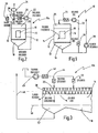
- a circulating air spray booth is shown in simplified form and denoted as a whole by the number 10.
- the circulating air spray booth 10 has a closed housing 12 in which a work area 14 for spray painting workpieces 16 is located.
- a wet scrubber 18 is provided below a floor 13, through which exhaust air is sucked off on the floor side.
- air is fed in at 90,000 m 3 / h via a fan 22 via one or more filters 24 and fed into the work area 14 from above via a filter ceiling 20 (also known as plenum).
- a part of the exhaust air sucked off via the wet scrubber 18 is sucked off via a further fan 28 and released to the outside, for example via the roof.
- Fig. 2 is a slightly modified version of the spray booth according to Fig. 1 shown and designated as a whole by numeral 10a.
- the working area 14 is supplied with circulating air via a fan 22 in circulating air mode via a filter 24 and a valve 32.
- the fan 22 has an output of 100,000 m 3 / h in recirculation mode. While 90,000 m 3 / h are passed into the working area 14 as recycled, filtered air, 10,000 m 3 / h are fed via a valve 32 to a thermal post-combustion 34, where it is thermally post-burned and finally released into the open.
- the thermal afterburning can preferably also be a regenerative thermal afterburning RNV.
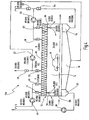
- FIG. 3 Another embodiment of a circulating air spray booth according to the invention is shown and denoted as a whole by number 10b.
- This is a larger spray booth, such as that used for painting vehicles in the automotive industry.
- the spray booth 10b has an elongated working area 14, which is only partially shown here, upstream of which an entrance area 38 (separate area at the entrance) is connected.
- a conveyor 50 runs through the spray booth 10b, by means of which workpieces 16 are moved continuously or cyclically over the input area 38 through the work area 14.
- the work area 14 has its own air duct, which is shown here in Fig. 3 is not shown.
- a fan 40 is provided for the entrance area 38, by means of which fresh air is sucked in from the outside and is fed into the entrance area 38 from above via a filter 42 and a valve 44 via the plenum 20.
- This is, for example, 50,000 m 3 / h.
- a part, namely 20,000 m 3 / h, passes through a suction area 52 of the entrance area 38 and is finally released to the environment via a line 48.
- 25,000 m 3 / h are diverted to work area 14.
- the remaining 5,000 m 3 / h are released into the environment as "overpressure".
- the spray booth 10b is therefore completely under excess pressure, so that no dust, foreign particles, etc.
- the second part of 25,000 m 3 / h is supplied to the work area 14 via a further air valve 46. With the aid of this air flow, effective ventilation of the work area 14 is ensured, so that effective ventilation takes place even with very long work areas 14. In the quick ventilation mode, there is no further diversion of air from the entrance area 38 to the work area 14.
- Fig. 4 is based on the previously based on Fig. 3
- the illustrated embodiment now shows a complete version of a spray booth 10c for vehicle painting in the automotive sector.
- the spray booth 10c has an elongated housing 12, with a work area 14, an entrance area 38 and an exit area 66. Again, workpieces 16 are guided by means of a conveyor 50 through the entrance area 38, the work area 14 and the exit area 66 of the spray booth 10c.
- the work area 14 as well as the entrance area 38 and the exit area 36 are provided with wet scrubbers or suction devices 18 and 52 and 54, respectively. Filtered air is supplied from above via the plenum 20.
- a fan 22 with 300,000 m 3 / h is used to supply 250,000 m 3 / h via a valve 32 as recycled, filtered air via the plenum 20 from above into the work area 14.
- a total of 300,000 m 3 / h are sucked off by means of the blower 22 via a wet scrubber 18, the remaining 50,000 m 3 / h are discharged to the outside via a valve 30 or fed to a thermal post-combustion.
- a blower 40 is provided at the entrance area 38, by means of which 80,000 m 3 / h are sucked in in recirculation mode and fed into the entrance area 38 via a valve 44 via the plenum 20.
- 50,000 m 3 / h reach the outside as exhaust air via the suction device 52 and a further fan 28. Another 25,000 m 3 / h are diverted to work area 14. The remaining 5,000 m 3 / h escape to the outside as overpressure at the entrance.
- a further blower 56 with 80,000 m 3 / h is provided in the exit area 66. These 80,000 m 3 / h are passed through a valve 60 from above via the plenum 20 into the outlet area 66. Of this, 50,000 m 3 / h reach the blower 56 via the suction device 54 and a valve 64. A further 30,000 m 3 / h are drawn in as fresh air via a valve 62 from the outside via the blower 56.
- a further portion of 25,000 m 3 / h of the air flow of 80,000 m 3 / h supplied via the valve 60 is diverted into the working area 14.
- the remaining portion of 5,000 m 3 / h escapes to the outside from the exit area 66, so that no ingress of dust and the like is possible here either.
- the two fans 40, 56 continue to run with the same output of 80,000 m 3 / h.
- the fan 22 is reduced to an output of 50,000 m 3 / h.
- These 50,000 m 3 / h continue to be discharged to the outside via the valve 30 or passed to thermal post-combustion.
- the valve 32 is closed so that no more recycled air can get into the working area 14.
- the valve position of the valve 44 is changed in such a way that only 55,000 m 3 / h reach the inlet area 38 via this valve 44.
- the remaining portion of 25,000 m 3 / h is fed via a valve 46 into the working area 14 via the plenum 20.
- the air flow of 55,000 m 3 / h in the entrance area 38 reaches the outside at 50,000 m 3 / h via the suction device 52 and the fan 28 as exhaust air, while 5,000 m 3 / h escape at the entrance as overpressure.
- air supplied from the valve 44 is no longer diverted into the working area 14.
- a valve 58 deflects part of the air flow of 80,000 m 3 / h, namely 25,000 m 3 / h, via the plenum 20 from above into the work area 14.
- the remaining portion of 55,000 m 3 / h is led through the exit area 66, with no more diversion into the work area 14.
- 50,000 m 3 / h return to the fan 56 via the suction device 54 and the valve 64, while the remaining 5,000 m 3 / h escape as overpressure at the outlet.
- the spray booth 10c is ventilated very quickly when switching to rapid venting mode. At the same time, it is avoided that the fan 56 has to be started up again from zero, so that start-up vibrations etc. that arise as a result are avoided.
Description
Die Erfindung betrifft eine Umluftspritzkabine mit einem Arbeitsbereich zur Beschichtung von Werkstücken, mit einer Absaugzone, aus der schadstoffhaltige, insbesondere lösungsmittelhaltige Abluft abgesaugt wird, und mit einem Gebläse zur Luftumwälzung, wobei die Abluft der Spritzkabine im Umluftbetrieb im Arbeitsbereich über mindestens eine Filtereinheit zumindest zum Teil als rezyklierte Luft wieder zuführbar ist.The invention relates to a circulating air spray booth with a work area for coating workpieces, with an extraction zone from which pollutant-containing, in particular solvent-containing, exhaust air is extracted, and with a fan for air circulation, the exhaust air from the spray booth in circulating air operation in the working area at least partially via at least one filter unit can be supplied again as recycled air.
Derartige Spritzkabinen sind als Umluftkabinen bekannt. Unter der Bezeichnung "Beschichtung" wird im Rahmen dieser Anmeldung vorzugsweise ein Spritzlackieren verstanden.Such spray booths are known as circulating air booths. In the context of this application, the term “coating” is preferably understood to mean spray painting.
Während sich bei der Rezyklierung der Abluft zwar über hochwertige Abscheidesysteme oder Filtereinrichtungen Staub und Fremdpartikel hochwirksam entfernen lassen, nimmt die Lösemittelkonzentration (gemessen in g/m3) im Laufe der Zeit zu. Die Konzentration der Lösemittel sollte wegen der Explosionssicherheit jedoch nicht über 5 g/m3 ansteigen.While the recycling of exhaust air can be highly effective in removing dust and foreign particles using high-quality separation systems or filter devices, the solvent concentration (measured in g / m 3 ) increases over time. The concentration of the solvents should, however, not exceed 5 g / m 3 because of explosion safety.
Soweit die Spritzkabine automatisch betrieben wird, spielt der Anstieg der Lösemittelkonzentration durch den Umluftbetrieb keine besondere Rolle, solange nicht die zulässigen Grenzwerte überschritten werden. Muss die Spritzkabine allerdings von einem Werker betreten werden, so ist die für Abluft zulässige Lösemittelkonzentration von maximal 5 g/m3 zu hoch, insbesondere wenn es sich um große Spritzkabinen handelt, wie sie beispielsweise in der Automobilindustrie eingesetzt werden. Ist der Spritzbetrieb unterbrochen, so erfolgt der Konzentrationsabbau der Lösemittelkonzentration allerdings nur sehr langsam. So dauert es in der Regel etwa 30 bis 60 Minuten, um die Lösemittelkonzentration ausgehend von beispielsweise einem zulässigen Maximalwert von 5,0 g/m3 auf einen annehmbaren Wert von zum Beispiel 0,01 g/m3 abzusenken.As long as the spray booth is operated automatically, the increase in the solvent concentration due to the recirculation mode does not play a special role as long as the permissible limit values are not exceeded. However, if the spray booth has to be entered by a worker, the maximum solvent concentration of 5 g / m 3 permitted for exhaust air is too high, especially when large spray booths are involved, such as those used in the automotive industry. If the spraying operation is interrupted, the solvent concentration will, however, only decrease very slowly. It usually takes about 30 to 60 minutes to lower the solvent concentration, starting from, for example, a maximum permissible value of 5.0 g / m 3 to an acceptable value of, for example, 0.01 g / m 3 .
Aus diesem Grunde haben sich Spritzkabinen, die im Umluftbetrieb arbeiten, bislang nur in Sonderfällen durchsetzen können. Insbesondere wenn es um große Spritzkabinen geht, wie sie beispielsweise in der Automobilindustrie gebräuchlich sind, gibt es praktisch keine Umluftspritzkabinen.For this reason, spray booths that work in recirculation mode have so far only been able to establish themselves in special cases. In particular, when it comes to large spray booths, such as those commonly used in the automotive industry, there are practically no circulating air spray booths.
Aus der
Allerdings handelt es sich hierbei nicht um eine Umluftspritzkabine im eigentlichen Sinne, da die Spritzkabine manuell von einem Werker benutzt wird, weshalb für ausreichende Zuluft im Arbeitsbereich des Werkers gesorgt werden muss.However, this is not a circulating air spray booth in the actual sense, since the spray booth is used manually by a worker, which is why sufficient supply air must be provided in the worker's work area.
Aus der
Vor diesem Hintergrund liegt der Erfindung die Aufgabe zugrunde, eine Umluftspritzkabine zu schaffen, die bei einer Unterbrechung des Spritzbetriebes eine schnelle Reduzierung der Lösemittelkonzentration auf einen zulässigen Wert zur Begehung der Spritzkabine ermöglicht. Hierbei soll ferner ein möglichst energiesparender Betrieb der Spritzkabine gewährleistet werden.Against this background, the invention is based on the object of creating a circulating air spray booth which, when the spraying operation is interrupted, enables the solvent concentration to be rapidly reduced to a permissible value for entering the spray booth. Furthermore, the most energy-saving operation of the spray booth should be ensured.
Diese Aufgabe wird durch eine Umluftspritzkabine gemäß Anspruch 1 gelöst.This object is achieved by a circulating air spray booth according to claim 1.
Da die Spritzkabine nämlich in einen Schnellentlüftungsbetrieb umschaltbar ist und in der dem Arbeitsbereich zumindest zum Teil nicht rezyklierte, vorzugsweise gefilterte, Zuluft zugeführt wird, ergibt sich ein schneller Austausch der im Arbeitsbereich vorhandenen lösemittelhaltigen Luft und damit ein schneller Konzentrationsabbau der Lösemittelkonzentration auf zulässige Werte. So wird schon nach kurzer Zeit nach Umschaltung in den Schnellentlüftungsbetrieb eine unbedenkliche Lösemittelkonzentration erreicht, so dass ein Werker ohne zusätzliche Schutzmaßnahmen wie etwa Atemmasken die Spritzkabine betreten kann.Since the spray booth can be switched to a quick ventilation mode and in which at least partially non-recycled, preferably filtered, supply air is supplied to the work area, the solvent-containing air present in the work area is exchanged more quickly and the solvent concentration is reduced to permissible values more quickly. A harmless solvent concentration is achieved after a short time after switching to quick exhaust operation, so that a worker can enter the spray booth without additional protective measures such as breathing masks.
Gemäß einer weiteren Ausgestaltung der Erfindung wird im Umluftbetrieb ein Teil der Abluft der Spritzkabine über eine Filtereinheit als rezyklierte Zuluft wieder zugeführt und ein Teil der Abluft über Dach oder eine Abluftreinigungsanlage an die Umgebung abgegeben.According to a further embodiment of the invention, in recirculation mode, part of the exhaust air is fed back into the spray booth via a filter unit as recycled supply air and part of the exhaust air is released to the environment via the roof or an exhaust air purification system.
Auf diese Weise ergibt sich eine ständige Lösungsmittelabgabe der rezyklierten Zuluft und eine ständige Zuführung eines gewissen Anteils von nicht rezyklierter Zuluft.This results in a constant release of solvent from the recycled supply air and a constant supply of a certain proportion of non-recycled supply air.
Gemäß einer weiteren Ausgestaltung der Erfindung wird die an die Umgebung abgegebene Abluft zuvor behandelt, vorzugsweise gewaschen, gefiltert und/oder thermisch nachbehandelt bzw. klimatisiert.According to a further embodiment of the invention, the exhaust air released into the environment is previously treated, preferably washed, filtered and / or thermally post-treated or air-conditioned.
Auf diese Weise werden die vorgeschriebenen Grenzwerte eingehalten bzw. kann mittels der thermischen Nachbehandlung (thermische Nachverbrennung) eine noch weitere Reduzierung der Schadstoffkonzentration erreicht werden.In this way, the prescribed limit values are complied with or a further reduction in the pollutant concentration can be achieved by means of thermal post-treatment (thermal post-combustion).
Gemäß einer weiteren Ausgestaltung der Erfindung ist die Spritzkabine allmählich zwischen einem Umluftbetrieb und einem Schnellentlüftungsbetrieb bzw. umgekehrt umschaltbar.According to a further embodiment of the invention, the spray booth can gradually be switched between a circulating air mode and a quick ventilation mode or vice versa.
Auf diese Weise können die zugehörigen Gebläse allmählich in die jeweils andere Position gebracht werden.In this way, the associated fans can gradually be brought into the other position will.
Hierzu ist zumindest ein regelbares Gebläse und ein kontinuierlich veränderbares Luftventil vorgesehen. In diesem Zusammenhang wird unter "Luftventil" ein irgendwie geartetes Ventil zur Regelung von Luft verstanden. Im einfachsten Fall handelt es sich hierbei um eine veränderbare Klappe mit Stellmotor.For this purpose, at least one controllable fan and one continuously variable air valve are provided. In this context, “air valve” is understood to mean a valve of some kind for regulating air. In the simplest case, this is a variable flap with a servomotor.
Das regelbare Gebläse weist in der Regel einen Frequenzumformer zur verlustarmen Regelung auf.The controllable fan usually has a frequency converter for low-loss control.
Gemäß einer weiteren Ausgestaltung der Erfindung umfasst die Spritzkabine einen Förderer zum Fördern von Werkstücken durch die Spritzkabine über einen Eingang durch den Arbeitsbereich und einen Ausgang, wobei mindestens ein abgetrennter Bereich am Eingang und vorzugsweise am Ausgang der Spritzkabine vorgesehen ist, der vom Arbeitsbereich getrennte Anschlüsse für Zu- und Abluft aufweist, wobei jeder abgetrennte Bereich gegenüber der Umgebung mit einem Überdruck beaufschlagbar ist.According to a further embodiment of the invention, the spray booth comprises a conveyor for conveying workpieces through the spray booth via an entrance through the work area and an exit, at least one separate area being provided at the entrance and preferably at the exit of the spray booth, the connections for separate connections from the work area Has supply and exhaust air, each separated area being able to be subjected to an overpressure with respect to the environment.
Auf diese Weise wird ein Eintritt von staubiger Luft in die Spritzkabine auf jeden Fall verhindert.In this way, entry of dusty air into the spray booth is definitely prevented.
Hierbei ist vorzugsweise mindestens ein Gebläse für den Arbeitsbereich und mindestens ein Gebläse für jeden abgetrennten Bereich vorgesehen, wobei dem Arbeitsbereich im Schnellentlüftungsbetrieb nicht rezyklierte, gefilterte Luft zuführbar ist.In this case, at least one fan is preferably provided for the work area and at least one fan for each separated area, with non-recycled, filtered air being able to be supplied to the work area in the quick ventilation mode.
Auf diese Weise wird bei einer Umschaltung in den Schnellentlüftungsbetrieb zusätzlich der Arbeitsbereich durch Zufuhr von nicht rezyklierter, gefilterter Luft von Lösemittemitteln befreit. Insbesondere bei lang ausgestalteten Spritzkabinen ist dies wichtig, um eine ausreichend schnelle Entlüftung zu gewährleisten.In this way, when switching to quick ventilation mode, the work area is also freed of solvents by supplying non-recycled, filtered air. This is particularly important in the case of spray booths with a long design, in order to ensure sufficiently rapid ventilation.
Hierbei kann die im Schnellentlüftungsbetrieb dem Arbeitsbereich zugeführte Luft aus zumindest einem abgetrennten Bereich abgezweigt werden.In this case, the air supplied to the work area in quick ventilation mode can be branched off from at least one separated area.
Läuft im Schnellentlüftungsbetrieb die Luftzufuhr für mindestens einen abgetrennten Bereich weiter, so kann auf diese Weise mit einfachen Mitteln eine schnelle Entlüftung des Arbeitsbereiches gewährleistet werden.If the air supply continues to run for at least one separated area in quick ventilation mode, rapid ventilation of the work area can be ensured in this way with simple means.
Vorzugsweise wird hierbei zumindest im abgetrennten Bereich am Eingang ausschließlich nicht rezyklierte, gefilterte Luft zugeführt.Preferably, only non-recycled, filtered air is fed in, at least in the separated area at the entrance.
Es ist jedoch auch denkbar, dass im abgetrennten Bereich, insbesondere am Ausgang, teilweise rezyklierte, gefilterte Luft und teilweise nicht rezyklierte Luft zugeführt wird.However, it is also conceivable that partially recycled, filtered air and partially non-recycled air are supplied in the separated area, in particular at the exit.
Dabei wird im Schnellentlüftungsbetrieb aus dem Arbeitsbereich abgesaugte Luft vorzugsweise nicht rezykliert, sondern als Abluft abgeführt.In this case, air sucked out of the work area in quick ventilation mode is preferably not recycled, but is discharged as exhaust air.
Durch diese Maßnahmen werden Anfahrprobleme, wie Schwingungen und Schläge, beim Anfahren von großen Gebläsen und eine damit verbundene Verschmutzungsgefahr vermieden.These measures prevent start-up problems such as vibrations and impacts when starting large fans and the associated risk of contamination.
In einer weiteren Ausgestaltung der Erfindung ist mindestens ein Nasswäscher bzw. eine Absaugung vorgesehen, über den z.B. bodenseitig Abluft abgesaugt wird. Die Spritzkabine ist hierbei grundsätzlich in bekannter Weise nach dem Stand der Technik aufgebaut, wobei die Spritzkabine auch mehrere wasserbeflutete Rieselwände aufweisen kann, die schließlich in einem gemeinsamen Aufnahmebehälter münden, über den bodenseitig Abluft abgesaugt werden kann, wobei es sich beispielsweise um einen Venturiwäscher oder dergleichen handeln kann. Vorzugsweise sind derartige Nasswäscher bzw. Absaugungen an jedem Teilbereich der Spritzkabine vorhanden.In a further embodiment of the invention, at least one wet scrubber or suction device is provided, via which e.g. exhaust air is extracted at the bottom. The spray booth is basically constructed in a known manner according to the state of the art, whereby the spray booth can also have several water-flooded trickle walls, which finally open into a common receptacle, through which exhaust air can be sucked off at the bottom, for example a venturi washer or the like can act. Such wet scrubbers or suction devices are preferably provided in each sub-area of the spray booth.
Gemäß einer weiteren vorteilhaften Ausgestaltung der Erfindung wird das Gebläse für den Arbeitsbereich im Schnellentlüftungsbetrieb mit derart reduzierter Leistung betrieben, dass ein Überdruck im Bereich der Filterdecke (Plenum) aufrechterhalten wird.According to a further advantageous embodiment of the invention, the fan for the work area is operated in quick ventilation mode with a reduced output such that an overpressure is maintained in the area of the filter ceiling (plenum).
Auf diese Weise werden Staubablösungen und Ablösungen von Fremdstoffen aus den Filtern weitgehend vermieden.In this way, dust and foreign matter from the filters are largely avoided.
Vorzugsweise wird bei der Umschaltung zwischen Umluftbetrieb und Schnellentlüftungsbetrieb die Gebläseleistung des Arbeitsbereiches allmählich reduziert und aus einem abgetrennten Bereich allmählich nicht rezyklierte, gefilterte Luft zugeführt.When switching between recirculation mode and quick ventilation mode, the fan power of the working area is preferably gradually reduced and filtered air that is not recycled is gradually supplied from a separate area.
Auf diese Weise können insbesondere Anfahrprobleme, die bei großen Gebläsen bestehen und die in der Regel zu Rütteln, Vibrationen und anderen Störungen führen, weitgehend vermieden werden.In this way, start-up problems that exist with large fans and that generally lead to shaking, vibrations and other disturbances can be largely avoided.
Umgekehrt wird bei der Umschaltung zwischen Schnellentlüftungsbetrieb und Umluftbetrieb die Gebläseleistung des Arbeitsbereiches vorzugsweise allmählich erhöht und aus einem abgetrennten Bereich zugeführte, nicht rezyklierte, gefilterte Luft allmählich wieder in den abgetrennten Bereich umgelenkt.Conversely, when switching between quick ventilation mode and circulating air mode, the fan output of the work area is preferably gradually increased and non-recycled, filtered air supplied from a separated area is gradually diverted back into the separated area.
Insgesamt werden durch diese Maßnahmen Anfahrprobleme bei großen Gebläsen weitgehend vermieden, so dass es möglich ist, für den Schnellentlüftungsbetrieb die Gebläseleistung im Arbeitsbereich deutlich zu reduzieren, während die Gebläseleistung in den abgetrennten Bereichen weiter aufrechterhalten werden kann.Overall, these measures largely avoid start-up problems with large fans, so that it is possible to significantly reduce the fan power in the work area for quick exhaust operation, while the fan power can be maintained in the separated areas.
Vorzugsweise wird der Arbeitsbereich ständig über eine Filtereinheit mit Zuluft versorgt, also sowohl während des Umluftbetriebs als auch während des Schnellentlüftungsbetriebs.The working area is preferably continuously supplied with air via a filter unit, that is to say both during circulating air operation and during quick ventilation operation.
Auf diese Weise steht die Filterdecke (das Plenum) ständig unter einem gewissen Überdruck, so dass keine Staubablösungen und dergleichen auftreten.In this way, the filter ceiling (the plenum) is constantly under a certain overpressure, so that no dust detachment and the like occur.
Es versteht sich, dass die vorstehend genannten und die nachstehend noch zu erläuternden Merkmale der Erfindung nicht nur in der jeweils angegebenen Kombination, sondern auch in anderen Kombinationen oder in Alleinstellung verwendbar sind, ohne den Rahmen der vorliegenden Erfindung zu verlassen.It goes without saying that the features of the invention mentioned above and those yet to be explained below can be used not only in the respectively specified combination, but also in other combinations or alone, without departing from the scope of the present invention.
Weitere Merkmale und Vorteile der Erfindung ergeben sich aus der nachfolgenden Beschreibung bevorzugter Ausführungsbeispiele unter Bezugnahme auf die Zeichnung. Es zeigen:
- Fig. 1
- eine stark vereinfachte Darstellung einer ersten Ausführung einer erfindungsgemäßen Umluftspritzkabine;
- Fig. 2
- eine abgewandelte Ausführung der Umluftspritzkabine gemäß
Fig. 1 ; - Fig. 3
- einen Teilbereich einer weiteren Ausführung einer erfindungsgemäßen Spritzkabine; und
- Fig. 4
- eine erfindungsgemäße Umluftspritzkabine, die insbesondere bei umfangreichen, besonders hochwertigen Lackierungen verwendet wird, wie etwa im Automobilbau.
- Fig. 1
- a greatly simplified representation of a first embodiment of a circulating air spray booth according to the invention;
- Fig. 2
- a modified version of the air circulation spray booth according to
Fig. 1 ; - Fig. 3
- a portion of a further embodiment of a spray booth according to the invention; and
- Fig. 4
- a circulating air spray booth according to the invention, which is used in particular for extensive, particularly high-quality paintwork, such as in automobile construction.
In sämtlichen
In
In
Auf diese Weise wird eine Schnellentlüftung gewährleistet. Gleichzeitig wird das Gebläse 22 nicht vollständig heruntergefahren, sondern läuft mit 10 % seiner Leistung weiter. Dies hat zur Folge, dass bei der Umschaltung zwischen Umluftbetrieb und Schnellentlüftungsbetrieb ein Anfahren des Gebläses 22 nicht notwendig ist. Auf diese Weise werden starke Rütteleffekte, Schläge usw., die beim Anfahren von Gebläsen auftreten, vermieden. Auf diese Weise werden Fremdpartikel, Staub, Schmutz usw., die sonst im Arbeitsbereich 14 beim Anfahren verstärkt auftreten könnten, weitgehend vermieden.In this way, quick ventilation is guaranteed. At the same time, the
In
Der Arbeitsbereich 14 verfügt über eine eigene Luftführung, die hier in
In
Zunächst sei der Umluftbetrieb erläutert. Über ein Gebläse 22 mit 300.000 m3/h werden 250.000 m3/h über ein Ventil 32 als rezyklierte, gefilterte Luft über das Plenum 20 von oben in den Arbeitsbereich 14 zugeführt. Über einen Nasswäscher 18 werden insgesamt 300.000 m3/h mittels des Gebläses 22 abgesaugt, die verbleibenden 50:000 m3/h werden über ein Ventil 30 nach außen abgegeben bzw. einer thermischen Nachverbrennung zugeführt. Am Eingangsbereich 38 ist ein Gebläse 40 vorgesehen, mittels dessen im Umluftbetrieb 80.000 m3/h angesaugt werden und über ein Ventil 44 über das Plenum 20 von oben in den Eingangsbereich 38 zugeführt werden. 50.000 m3/h gelangen über die Absaugung 52 und ein weiteres Gebläse 28 als Abluft nach außen. Weitere 25.000 m3/h werden in den Arbeitsbereich 14 umgelenkt. Die verbleibenden 5.000 m3/h entweichen als Überdruck am Eingang nach außen. Im Ausgangsbereich 66 ist ein weiteres Gebläse 56 mit 80.000 m3/h vorgesehen. Diese 80.000 m3/h werden über ein Ventil 60 von oben über das Plenum 20 in den Ausgangsbereich 66 geleitet. Hiervon gelangen 50.000 m3/h über die Absaugung 54 und ein Ventil 64 zurück zum Gebläse 56. Weitere 30.000 m3/h werden als Frischluft über ein Ventil 62 von außen über das Gebläse 56 angesaugt. Vom über das Ventil 60 zugeführten Luftstrom von 80.000 m3/h wird ein weiterer Anteil von 25.000 m3/h in den Arbeitsbereich 14 umgelenkt. Der verbleibende Anteil von 5.000 m3/h entweicht aus dem Ausgangsbereich 66 nach außen, so dass auch hier kein Eindringen von Staub und dergleichen möglich ist.First, the recirculation mode will be explained. A
Wird die Spritzkabine 10c nunmehr auf Schnellentlüftungsbetrieb umgeschaltet, so laufen die beiden Gebläse 40, 56 mit gleicher Leistung von 80.000 m3/h weiter. Dagegen wird das Gebläse 22 auf eine Leistung von 50.000 m3/h reduziert. Diese 50.000 m3/h werden weiterhin über das Ventil 30 nach außen abgegeben bzw. zur thermischen Nachverbrennung geführt. Das Ventil 32 wird geschlossen, so dass keine rezyklierte Luft mehr in den Arbeitsbereich 14 gelangt. Am Eingangsbereich 38 wird die Ventilstellung des Ventils 44 derart geändert, so dass über dieses Ventil 44 nur noch 55.000 m3/h in den Eingangsbereich 38 gelangen. Der verbleibende Anteil von 25.000 m3/h wird über ein Ventil 46 in den Arbeitsbereich 14 über das Plenum 20 zugeführt. Der Luftstrom von 55.000 m3/h im Eingangsbereich 38 gelangt mit 50.000 m3/h über die Absaugung 52 und das Gebläse 28 als Abluft nach außen, während 5.000 m3/h am Eingang als Überdruck entweichen. In dem Arbeitsbereich 14 wird aus dem Ventil 44 zugeführte Luft nicht mehr in den Arbeitsbereich 14 umgelenkt. Am Ausgangsbereich 66 wird über ein Ventil 58 ein Teil des Luftstroms von 80.000 m3/h, nämlich 25.000 m3/h, über das Plenum 20 von oben in den Arbeitsbereich 14 umgelenkt. Der verbleibende Anteil von 55.000 m3/h wird durch den Ausgangsbereich 66 geführt, wobei keine Umleitung mehr in den Arbeitsbereich 14 erfolgt. 50.000 m3/h gelangen über die Absaugung 54 und das Ventil 64 zurück zum Gebläse 56, während die verbleibenden 5.000 m3/h als Überdruck am Ausgang entweichen.If the spray booth 10c is now switched to quick ventilation mode, the two
Am Ausgangsbereich 66 wird somit im Schnellentlüftungsbetrieb immer noch ein Teil als rezyklierte Luft wieder zurückgeführt. Es wäre jedoch ohne Weiteres denkbar, auch die Luftführung am Ausgangsbereich 66 identisch wie am Eingangsbereich 38 vorzusehen, so dass keinerlei rezyklierte Luft zugeführt wird.At the
Aufgrund der dargestellten Maßnahmen ergibt sich eine sehr schnelle Entlüftung der Spritzkabine 10c bei Umschaltung in den Schnellentlüftungsbetrieb. Gleichzeitig wird vermieden, dass das Gebläse 56 wieder von Null auf angefahren werden muss, so dass dadurch entstehende Anfahrvibrationen usw. vermieden werden.Due to the measures shown, the spray booth 10c is ventilated very quickly when switching to rapid venting mode. At the same time, it is avoided that the
Claims (18)
- Recirculating-air spray booth with a working region (14) for coating workpieces (16), with an extraction zone from which solvent-containing exhaust air is extracted, and with a fan (22) for circulating the air, and with a recirculating-air mode within which at least part of the exhaust air can be resupplied as recycled air to the spray booth (10, 10a, b, c) via at least one filter unit (20, 24), wherein the spray booth (10, 10a, b, c) can be switched over into a further mode of operation, wherein the supply of recycled air is interrupted or reduced and additional air which is at least partially not recycled, can be supplied to the working region (14), wherein the recirculating-air spray booth is configured for working in the recirculating-air mode during the coating of workpieces, and wherein a switching over into the further mode of operation is effected upon interruption of the recirculating-air mode, the further mode of operation being configured as a rapid venting mode for a fast reduction of a solvent concentration to an admissible value which allows access to the spray booth without any additional protective measures, characterized in that the fan (22) for the operating region (14), when being in rapid venting mode, is operated with reduced power.
- The spray booth of claim 1, wherein a part of the exhaust air from the spray booth (10, 10a, b, c) is resupplied via a filter unit (20, 24) as recycled air, when being in recirculating-air mode, and a part of the exhaust air is released to the surroundings.
- The spray booth of claim 2, wherein the exhaust air released to the surroundings is treated before, preferably being washed, filtered absorbed and/or thermally finally treated.
- The spray booth according to any of the preceding claims which can be switched over gradually between a recirculating-air mode and a rapid venting mode.
- The spray booth according to any of the preceding claims, which comprises at least an adjustable fan (22) and/or an air valve (30, 32, 44, 46, 58, 60) which can be continually adjusted.
- The spray booth of claim 5, wherein the adjustable fan (22) comprises a frequency converter.
- The spray booth of any of the preceding claims, with a conveyor (50) for transporting workpieces (16) through the spray booth (10b, c) via an entrance through the working region (14) and an exit, wherein at least a separated region (38, 66) is provided at the entrance and preferably at the exit of the spray booth (10b, c), the exit comprising connections for air supply and exhaust air separated from the working region (14), wherein each separated region (38, 66) can be accessed with a pressure which is higher than the surrounding pressure.
- The spray booth of claim 7, with at least one fan (22) for the working region (14) and at least one fan (40, 56) for each separate region (38, 66), wherein non-recycled filtered air can be supplied to the working region (14) when being in rapid venting mode.
- The spray booth of claim 8, wherein in the rapid venting mode the air supplied to the working region (14) is divided from at least one separated region (38, 66).
- The spray booth of claim 8 or 9, wherein at least the separated region (38) at its entrance can be supplied only with recycled, filtered air.
- The spray booth of any of claims 8 to 10, wherein which the separated region (66) at its exit can be supplied at least partially with recycled, filtered air, and at least partially with non-recycled air.
- The spray booth according to any of claims 8 to 11, wherein air aspirated from the working region (14) in the rapid venting mode is not recycled, but output as exhaust air.
- The spray booth of any of the preceding claims, further comprising at least one wet washer (18, 52, 54), from which exhaust air is aspirated on the bottom side.
- The spray booth of any of claims 8 to 13, wherein the working region and each separated region (38, 66) comprises a wet washer (52, 54), a suction or a dry separator through which exhaust air is aspirated on the bottom side and/or wall side.
- The spray booth of any of claims 12 to 13, wherein the fan (22) for the working region (14) is operated in the rapid venting mode at such a reduced power that an overpressure is maintained in the filter ceiling (20).
- The spray booth of any of claims 8 to 15, wherein during switching between recirculating-air mode and rapid venting mode the fan power of the working region (14) is reduced gradually, and from a separated region (38) non-recycled, filtered air is supplied gradually.
- The spray booth of any of claims 8 to 16, wherein, when switching between the rapid venting mode and the recirculating-air mode the fan power of the working region (14) is gradually increased, and previously supplied non-recycled, filtered air is gradually diverted again into the separated region (38).
- The spray booth of any of the preceding claims, with a filter unit for supplying air into the working region, by means of which the working region is supplied with air during recirculating-air mode as well as during rapid venting mode.
Priority Applications (1)
| Application Number | Priority Date | Filing Date | Title |
|---|---|---|---|
| PL11719560T PL2437895T5 (en) | 2010-05-17 | 2011-05-13 | Recirculating-air spray booth |
Applications Claiming Priority (2)
| Application Number | Priority Date | Filing Date | Title |
|---|---|---|---|
| DE102010021540A DE102010021540A1 (en) | 2010-05-17 | 2010-05-17 | Recirculated air spray booth |
| PCT/EP2011/057755 WO2011144527A1 (en) | 2010-05-17 | 2011-05-13 | Recirculating-air spray booth |
Publications (3)
| Publication Number | Publication Date |
|---|---|
| EP2437895A1 EP2437895A1 (en) | 2012-04-11 |
| EP2437895B1 EP2437895B1 (en) | 2014-01-22 |
| EP2437895B2 true EP2437895B2 (en) | 2020-11-04 |
Family
ID=44170471
Family Applications (1)
| Application Number | Title | Priority Date | Filing Date |
|---|---|---|---|
| EP11719560.2A Active EP2437895B2 (en) | 2010-05-17 | 2011-05-13 | Recirculating-air spray booth |
Country Status (6)
| Country | Link |
|---|---|
| EP (1) | EP2437895B2 (en) |
| DE (1) | DE102010021540A1 (en) |
| ES (1) | ES2445766T5 (en) |
| PL (1) | PL2437895T5 (en) |
| PT (1) | PT2437895E (en) |
| WO (1) | WO2011144527A1 (en) |
Families Citing this family (3)
| Publication number | Priority date | Publication date | Assignee | Title |
|---|---|---|---|---|
| DE202012103894U1 (en) * | 2012-10-11 | 2014-01-15 | Dürr Systems GmbH | A surface treatment device |
| DE102016114466A1 (en) * | 2016-08-04 | 2018-02-08 | Eisenmann Se | Conditioning device and method for conditioning a gaseous medium and system and method for treating workpieces |
| EP3618795A4 (en) | 2017-05-05 | 2021-04-14 | Badri Amurthur | Stimulation methods and apparatus |
Citations (2)
| Publication number | Priority date | Publication date | Assignee | Title |
|---|---|---|---|---|
| DE3334257C1 (en) † | 1983-09-22 | 1985-02-14 | RMG Beierling GmbH, 4791 Altenbeken | Painting and evaporation system with forced air ventilation |
| DE19941184A1 (en) † | 1999-08-30 | 2001-03-01 | Flaekt Ab | Paint dryer and paint dryer system |
Family Cites Families (5)
| Publication number | Priority date | Publication date | Assignee | Title |
|---|---|---|---|---|
| SE454328B (en) | 1982-04-30 | 1988-04-25 | Flaekt Ab | PROCEDURE AND DEVICE FOR VENTILATION OF A SPRAYBOX |
| DE4228660A1 (en) * | 1992-08-28 | 1994-03-03 | Alfred Feige | Ventilation device for paint booths or the like |
| US5643077A (en) * | 1995-06-16 | 1997-07-01 | Ayer; Jacqueline | Continually optimized, variable flow rate ventilation system |
| DE50114835D1 (en) * | 2001-01-15 | 2009-05-28 | Bolin Heatex Technology Gmbh | Ventilation device for a spray booth of a paint shop |
| DE102007015150A1 (en) * | 2007-03-02 | 2008-09-04 | Wurster, Gerd | Paint spraying plant with booth, has separate air conditioning equipment for coating zone and air supplies for auxiliary zones on either side |
-
2010
- 2010-05-17 DE DE102010021540A patent/DE102010021540A1/en not_active Withdrawn
-
2011
- 2011-05-13 PL PL11719560T patent/PL2437895T5/en unknown
- 2011-05-13 EP EP11719560.2A patent/EP2437895B2/en active Active
- 2011-05-13 WO PCT/EP2011/057755 patent/WO2011144527A1/en active Application Filing
- 2011-05-13 PT PT117195602T patent/PT2437895E/en unknown
- 2011-05-13 ES ES11719560T patent/ES2445766T5/en active Active
Patent Citations (2)
| Publication number | Priority date | Publication date | Assignee | Title |
|---|---|---|---|---|
| DE3334257C1 (en) † | 1983-09-22 | 1985-02-14 | RMG Beierling GmbH, 4791 Altenbeken | Painting and evaporation system with forced air ventilation |
| DE19941184A1 (en) † | 1999-08-30 | 2001-03-01 | Flaekt Ab | Paint dryer and paint dryer system |
Also Published As
| Publication number | Publication date |
|---|---|
| ES2445766T3 (en) | 2014-03-05 |
| WO2011144527A1 (en) | 2011-11-24 |
| PL2437895T3 (en) | 2014-06-30 |
| EP2437895A1 (en) | 2012-04-11 |
| PT2437895E (en) | 2014-03-27 |
| DE102010021540A1 (en) | 2011-11-17 |
| PL2437895T5 (en) | 2021-03-08 |
| ES2445766T5 (en) | 2021-06-18 |
| EP2437895B1 (en) | 2014-01-22 |
Similar Documents
| Publication | Publication Date | Title |
|---|---|---|
| EP0438076B1 (en) | Air distributing arrangement for vehicle cabins | |
| EP2026910B1 (en) | Painting system | |
| EP2736655B1 (en) | Compact painting facility | |
| DE2928226A1 (en) | PAINT SPRAYING SYSTEMS FOR OBJECT AND ENERGY-SAVING METHOD FOR SPRAYING | |
| EP2814619B1 (en) | Method for treating objects and system therefor | |
| EP2244840B2 (en) | Device and method for supplying air to an application zone of a paint booth | |
| EP2437895B2 (en) | Recirculating-air spray booth | |
| DE2710254A1 (en) | METHOD AND DEVICE FOR VENTILATING PAINT SPRAYING SYSTEMS | |
| WO2018086731A1 (en) | Drying chamber | |
| DE202015105649U1 (en) | Indoor ventilation system | |
| EP2244839B1 (en) | Painting system | |
| DE202011001810U1 (en) | Exhaust air cleaning system for livestock houses | |
| DE202020103567U1 (en) | Treatment facility | |
| EP2117723B1 (en) | Method and device for removing solids from overspray generated on painting objects | |
| EP4144450A1 (en) | Method for cleaning exhaust air generated in a processing process in a clean room/dry room, and system for carrying out the method | |
| WO2021063444A1 (en) | Treatment system and treatment method | |
| EP2923773B1 (en) | Assembly for removing varnish fog when varnishing a component such as the fuselage of an aircraft and varnish removal method | |
| DE19912361B4 (en) | paint shop | |
| DE202020106913U1 (en) | Air cleaning device for cleaning room air | |
| DE102019215080A1 (en) | Treatment facility and treatment process | |
| EP0253980A1 (en) | Method and apparatus for purifying waste gas of a manually operated spray booth | |
| DE2947334A1 (en) | SUCTION BOX | |
| DE102021126089B3 (en) | Procedure for load-dependent dryer adjustment and dryer | |
| EP0584638A2 (en) | Ventilation device for spraying booths or similar | |
| WO2000061308A1 (en) | Roll stand |
Legal Events
| Date | Code | Title | Description |
|---|---|---|---|
| PUAI | Public reference made under article 153(3) epc to a published international application that has entered the european phase |
Free format text: ORIGINAL CODE: 0009012 |
|
| 17P | Request for examination filed |
Effective date: 20111228 |
|
| AK | Designated contracting states |
Kind code of ref document: A1 Designated state(s): AL AT BE BG CH CY CZ DE DK EE ES FI FR GB GR HR HU IE IS IT LI LT LU LV MC MK MT NL NO PL PT RO RS SE SI SK SM TR |
|
| 17Q | First examination report despatched |
Effective date: 20121009 |
|
| GRAP | Despatch of communication of intention to grant a patent |
Free format text: ORIGINAL CODE: EPIDOSNIGR1 |
|
| DAX | Request for extension of the european patent (deleted) | ||
| INTG | Intention to grant announced |
Effective date: 20130805 |
|
| GRAS | Grant fee paid |
Free format text: ORIGINAL CODE: EPIDOSNIGR3 |
|
| GRAA | (expected) grant |
Free format text: ORIGINAL CODE: 0009210 |
|
| RAP1 | Party data changed (applicant data changed or rights of an application transferred) |
Owner name: DUERR SYSTEMS GMBH |
|
| AK | Designated contracting states |
Kind code of ref document: B1 Designated state(s): AL AT BE BG CH CY CZ DE DK EE ES FI FR GB GR HR HU IE IS IT LI LT LU LV MC MK MT NL NO PL PT RO RS SE SI SK SM TR |
|
| REG | Reference to a national code |
Ref country code: GB Ref legal event code: FG4D Free format text: NOT ENGLISH |
|
| REG | Reference to a national code |
Ref country code: CH Ref legal event code: EP |
|
| REG | Reference to a national code |
Ref country code: AT Ref legal event code: REF Ref document number: 650515 Country of ref document: AT Kind code of ref document: T Effective date: 20140215 |
|
| REG | Reference to a national code |
Ref country code: IE Ref legal event code: FG4D Free format text: LANGUAGE OF EP DOCUMENT: GERMAN |
|
| REG | Reference to a national code |
Ref country code: ES Ref legal event code: FG2A Ref document number: 2445766 Country of ref document: ES Kind code of ref document: T3 Effective date: 20140305 |
|
| REG | Reference to a national code |
Ref country code: DE Ref legal event code: R096 Ref document number: 502011002109 Country of ref document: DE Effective date: 20140306 |
|
| REG | Reference to a national code |
Ref country code: PT Ref legal event code: SC4A Free format text: AVAILABILITY OF NATIONAL TRANSLATION Effective date: 20140320 |
|
| REG | Reference to a national code |
Ref country code: RO Ref legal event code: EPE |
|
| REG | Reference to a national code |
Ref country code: NL Ref legal event code: T3 |
|
| REG | Reference to a national code |
Ref country code: LT Ref legal event code: MG4D |
|
| REG | Reference to a national code |
Ref country code: PL Ref legal event code: T3 |
|
| REG | Reference to a national code |
Ref country code: SK Ref legal event code: T3 Ref document number: E 16187 Country of ref document: SK |
|
| PG25 | Lapsed in a contracting state [announced via postgrant information from national office to epo] |
Ref country code: LT Free format text: LAPSE BECAUSE OF FAILURE TO SUBMIT A TRANSLATION OF THE DESCRIPTION OR TO PAY THE FEE WITHIN THE PRESCRIBED TIME-LIMIT Effective date: 20140122 Ref country code: IS Free format text: LAPSE BECAUSE OF FAILURE TO SUBMIT A TRANSLATION OF THE DESCRIPTION OR TO PAY THE FEE WITHIN THE PRESCRIBED TIME-LIMIT Effective date: 20140522 Ref country code: NO Free format text: LAPSE BECAUSE OF FAILURE TO SUBMIT A TRANSLATION OF THE DESCRIPTION OR TO PAY THE FEE WITHIN THE PRESCRIBED TIME-LIMIT Effective date: 20140422 |
|
| PG25 | Lapsed in a contracting state [announced via postgrant information from national office to epo] |
Ref country code: CY Free format text: LAPSE BECAUSE OF FAILURE TO SUBMIT A TRANSLATION OF THE DESCRIPTION OR TO PAY THE FEE WITHIN THE PRESCRIBED TIME-LIMIT Effective date: 20140122 Ref country code: SE Free format text: LAPSE BECAUSE OF FAILURE TO SUBMIT A TRANSLATION OF THE DESCRIPTION OR TO PAY THE FEE WITHIN THE PRESCRIBED TIME-LIMIT Effective date: 20140122 |
|
| PG25 | Lapsed in a contracting state [announced via postgrant information from national office to epo] |
Ref country code: LV Free format text: LAPSE BECAUSE OF FAILURE TO SUBMIT A TRANSLATION OF THE DESCRIPTION OR TO PAY THE FEE WITHIN THE PRESCRIBED TIME-LIMIT Effective date: 20140122 Ref country code: RS Free format text: LAPSE BECAUSE OF FAILURE TO SUBMIT A TRANSLATION OF THE DESCRIPTION OR TO PAY THE FEE WITHIN THE PRESCRIBED TIME-LIMIT Effective date: 20140122 Ref country code: HR Free format text: LAPSE BECAUSE OF FAILURE TO SUBMIT A TRANSLATION OF THE DESCRIPTION OR TO PAY THE FEE WITHIN THE PRESCRIBED TIME-LIMIT Effective date: 20140122 |
|
| REG | Reference to a national code |
Ref country code: DE Ref legal event code: R026 Ref document number: 502011002109 Country of ref document: DE |
|
| PG25 | Lapsed in a contracting state [announced via postgrant information from national office to epo] |
Ref country code: EE Free format text: LAPSE BECAUSE OF FAILURE TO SUBMIT A TRANSLATION OF THE DESCRIPTION OR TO PAY THE FEE WITHIN THE PRESCRIBED TIME-LIMIT Effective date: 20140122 Ref country code: DK Free format text: LAPSE BECAUSE OF FAILURE TO SUBMIT A TRANSLATION OF THE DESCRIPTION OR TO PAY THE FEE WITHIN THE PRESCRIBED TIME-LIMIT Effective date: 20140122 |
|
| PLBI | Opposition filed |
Free format text: ORIGINAL CODE: 0009260 |
|
| PLAX | Notice of opposition and request to file observation + time limit sent |
Free format text: ORIGINAL CODE: EPIDOSNOBS2 |
|
| 26 | Opposition filed |
Opponent name: EISENMANN SE Effective date: 20141017 |
|
| PG25 | Lapsed in a contracting state [announced via postgrant information from national office to epo] |
Ref country code: LU Free format text: LAPSE BECAUSE OF FAILURE TO SUBMIT A TRANSLATION OF THE DESCRIPTION OR TO PAY THE FEE WITHIN THE PRESCRIBED TIME-LIMIT Effective date: 20140513 |
|
| REG | Reference to a national code |
Ref country code: CH Ref legal event code: PL |
|
| REG | Reference to a national code |
Ref country code: DE Ref legal event code: R026 Ref document number: 502011002109 Country of ref document: DE Effective date: 20141017 |
|
| PG25 | Lapsed in a contracting state [announced via postgrant information from national office to epo] |
Ref country code: MC Free format text: LAPSE BECAUSE OF FAILURE TO SUBMIT A TRANSLATION OF THE DESCRIPTION OR TO PAY THE FEE WITHIN THE PRESCRIBED TIME-LIMIT Effective date: 20140122 Ref country code: LI Free format text: LAPSE BECAUSE OF NON-PAYMENT OF DUE FEES Effective date: 20140531 Ref country code: CH Free format text: LAPSE BECAUSE OF NON-PAYMENT OF DUE FEES Effective date: 20140531 |
|
| REG | Reference to a national code |
Ref country code: IE Ref legal event code: MM4A |
|
| REG | Reference to a national code |
Ref country code: HU Ref legal event code: AG4A Ref document number: E021898 Country of ref document: HU |
|
| PLAF | Information modified related to communication of a notice of opposition and request to file observations + time limit |
Free format text: ORIGINAL CODE: EPIDOSCOBS2 |
|
| PG25 | Lapsed in a contracting state [announced via postgrant information from national office to epo] |
Ref country code: IE Free format text: LAPSE BECAUSE OF NON-PAYMENT OF DUE FEES Effective date: 20140513 |
|
| PG25 | Lapsed in a contracting state [announced via postgrant information from national office to epo] |
Ref country code: SI Free format text: LAPSE BECAUSE OF FAILURE TO SUBMIT A TRANSLATION OF THE DESCRIPTION OR TO PAY THE FEE WITHIN THE PRESCRIBED TIME-LIMIT Effective date: 20140122 |
|
| PLBB | Reply of patent proprietor to notice(s) of opposition received |
Free format text: ORIGINAL CODE: EPIDOSNOBS3 |
|
| PG25 | Lapsed in a contracting state [announced via postgrant information from national office to epo] |
Ref country code: MT Free format text: LAPSE BECAUSE OF FAILURE TO SUBMIT A TRANSLATION OF THE DESCRIPTION OR TO PAY THE FEE WITHIN THE PRESCRIBED TIME-LIMIT Effective date: 20140122 |
|
| PG25 | Lapsed in a contracting state [announced via postgrant information from national office to epo] |
Ref country code: SM Free format text: LAPSE BECAUSE OF FAILURE TO SUBMIT A TRANSLATION OF THE DESCRIPTION OR TO PAY THE FEE WITHIN THE PRESCRIBED TIME-LIMIT Effective date: 20140122 |
|
| REG | Reference to a national code |
Ref country code: FR Ref legal event code: PLFP Year of fee payment: 6 |
|
| PG25 | Lapsed in a contracting state [announced via postgrant information from national office to epo] |
Ref country code: GR Free format text: LAPSE BECAUSE OF FAILURE TO SUBMIT A TRANSLATION OF THE DESCRIPTION OR TO PAY THE FEE WITHIN THE PRESCRIBED TIME-LIMIT Effective date: 20140423 Ref country code: BG Free format text: LAPSE BECAUSE OF FAILURE TO SUBMIT A TRANSLATION OF THE DESCRIPTION OR TO PAY THE FEE WITHIN THE PRESCRIBED TIME-LIMIT Effective date: 20140122 |
|
| PG25 | Lapsed in a contracting state [announced via postgrant information from national office to epo] |
Ref country code: BE Free format text: LAPSE BECAUSE OF FAILURE TO SUBMIT A TRANSLATION OF THE DESCRIPTION OR TO PAY THE FEE WITHIN THE PRESCRIBED TIME-LIMIT Effective date: 20140531 |
|
| REG | Reference to a national code |
Ref country code: DE Ref legal event code: R082 Ref document number: 502011002109 Country of ref document: DE Representative=s name: WITTE, WELLER & PARTNER PATENTANWAELTE MBB, DE Ref country code: DE Ref legal event code: R081 Ref document number: 502011002109 Country of ref document: DE Owner name: DUERR SYSTEMS AG, DE Free format text: FORMER OWNER: DUERR SYSTEMS GMBH, 74321 BIETIGHEIM-BISSINGEN, DE |
|
| RAP2 | Party data changed (patent owner data changed or rights of a patent transferred) |
Owner name: DUERR SYSTEMS AG |
|
| REG | Reference to a national code |
Ref country code: NL Ref legal event code: PD Owner name: DUERR SYSTEMS AG; DE Free format text: DETAILS ASSIGNMENT: CHANGE OF OWNER(S), CHANGE OF LEGAL ENTITY; FORMER OWNER NAME: DUERR SYSTEMS AG Effective date: 20161025 |
|
| REG | Reference to a national code |
Ref country code: FR Ref legal event code: CD Owner name: DURR SYSTEMS AG, DE Effective date: 20161026 |
|
| REG | Reference to a national code |
Ref country code: HU Ref legal event code: FH1C Free format text: FORMER REPRESENTATIVE(S): ERDELY PETER - DANUBIA SZABADALMI ES JOGI IRODA KFT., HU Representative=s name: DANUBIA SZABADALMI ES JOGI IRODA KFT., HU Ref country code: HU Ref legal event code: GB9C Owner name: DUERR SYSTEMS AG, DE Free format text: FORMER OWNER(S): DUERR SYSTEMS GMBH, DE |
|
| REG | Reference to a national code |
Ref country code: SK Ref legal event code: TC4A Ref document number: E 16187 Country of ref document: SK Owner name: DUERR SYSTEMS AG, BIETIGHEIM-BISSINGEN, DE Effective date: 20170110 |
|
| REG | Reference to a national code |
Ref country code: AT Ref legal event code: PC Ref document number: 650515 Country of ref document: AT Kind code of ref document: T Owner name: DUERR SYSTEMS AG, DE Effective date: 20161223 |
|
| APBM | Appeal reference recorded |
Free format text: ORIGINAL CODE: EPIDOSNREFNO |
|
| APBP | Date of receipt of notice of appeal recorded |
Free format text: ORIGINAL CODE: EPIDOSNNOA2O |
|
| APAH | Appeal reference modified |
Free format text: ORIGINAL CODE: EPIDOSCREFNO |
|
| REG | Reference to a national code |
Ref country code: FR Ref legal event code: PLFP Year of fee payment: 7 |
|
| APBQ | Date of receipt of statement of grounds of appeal recorded |
Free format text: ORIGINAL CODE: EPIDOSNNOA3O |
|
| PLAB | Opposition data, opponent's data or that of the opponent's representative modified |
Free format text: ORIGINAL CODE: 0009299OPPO |
|
| R26 | Opposition filed (corrected) |
Opponent name: EISENMANN SE Effective date: 20141017 |
|
| REG | Reference to a national code |
Ref country code: DE Ref legal event code: R079 Ref document number: 502011002109 Country of ref document: DE Free format text: PREVIOUS MAIN CLASS: B05B0015120000 Ipc: B05B0016000000 |
|
| REG | Reference to a national code |
Ref country code: FR Ref legal event code: PLFP Year of fee payment: 8 |
|
| PG25 | Lapsed in a contracting state [announced via postgrant information from national office to epo] |
Ref country code: MK Free format text: LAPSE BECAUSE OF FAILURE TO SUBMIT A TRANSLATION OF THE DESCRIPTION OR TO PAY THE FEE WITHIN THE PRESCRIBED TIME-LIMIT Effective date: 20140122 |
|
| PG25 | Lapsed in a contracting state [announced via postgrant information from national office to epo] |
Ref country code: AL Free format text: LAPSE BECAUSE OF FAILURE TO SUBMIT A TRANSLATION OF THE DESCRIPTION OR TO PAY THE FEE WITHIN THE PRESCRIBED TIME-LIMIT Effective date: 20140122 |
|
| APBU | Appeal procedure closed |
Free format text: ORIGINAL CODE: EPIDOSNNOA9O |
|
| PGFP | Annual fee paid to national office [announced via postgrant information from national office to epo] |
Ref country code: TR Payment date: 20200512 Year of fee payment: 10 |
|
| PUAH | Patent maintained in amended form |
Free format text: ORIGINAL CODE: 0009272 |
|
| STAA | Information on the status of an ep patent application or granted ep patent |
Free format text: STATUS: PATENT MAINTAINED AS AMENDED |
|
| 27A | Patent maintained in amended form |
Effective date: 20201104 |
|
| AK | Designated contracting states |
Kind code of ref document: B2 Designated state(s): AL AT BE BG CH CY CZ DE DK EE ES FI FR GB GR HR HU IE IS IT LI LT LU LV MC MK MT NL NO PL PT RO RS SE SI SK SM TR |
|
| REG | Reference to a national code |
Ref country code: DE Ref legal event code: R102 Ref document number: 502011002109 Country of ref document: DE |
|
| REG | Reference to a national code |
Ref country code: SK Ref legal event code: T5 Ref document number: E 16187 Country of ref document: SK |
|
| REG | Reference to a national code |
Ref country code: NL Ref legal event code: FP |
|
| REG | Reference to a national code |
Ref country code: ES Ref legal event code: DC2A Ref document number: 2445766 Country of ref document: ES Kind code of ref document: T5 Effective date: 20210618 |
|
| PGFP | Annual fee paid to national office [announced via postgrant information from national office to epo] |
Ref country code: NL Payment date: 20210519 Year of fee payment: 11 Ref country code: RO Payment date: 20210429 Year of fee payment: 11 |
|
| PGFP | Annual fee paid to national office [announced via postgrant information from national office to epo] |
Ref country code: GB Payment date: 20210525 Year of fee payment: 11 Ref country code: AT Payment date: 20210520 Year of fee payment: 11 |
|
| REG | Reference to a national code |
Ref country code: NL Ref legal event code: MM Effective date: 20220601 |
|
| REG | Reference to a national code |
Ref country code: AT Ref legal event code: MM01 Ref document number: 650515 Country of ref document: AT Kind code of ref document: T Effective date: 20220513 |
|
| GBPC | Gb: european patent ceased through non-payment of renewal fee |
Effective date: 20220513 |
|
| PG25 | Lapsed in a contracting state [announced via postgrant information from national office to epo] |
Ref country code: RO Free format text: LAPSE BECAUSE OF NON-PAYMENT OF DUE FEES Effective date: 20220513 Ref country code: AT Free format text: LAPSE BECAUSE OF NON-PAYMENT OF DUE FEES Effective date: 20220513 |
|
| PG25 | Lapsed in a contracting state [announced via postgrant information from national office to epo] |
Ref country code: GB Free format text: LAPSE BECAUSE OF NON-PAYMENT OF DUE FEES Effective date: 20220513 |
|
| PG25 | Lapsed in a contracting state [announced via postgrant information from national office to epo] |
Ref country code: NL Free format text: LAPSE BECAUSE OF NON-PAYMENT OF DUE FEES Effective date: 20220601 |
|
| PGFP | Annual fee paid to national office [announced via postgrant information from national office to epo] |
Ref country code: PT Payment date: 20230504 Year of fee payment: 13 Ref country code: IT Payment date: 20230522 Year of fee payment: 13 Ref country code: FR Payment date: 20230526 Year of fee payment: 13 Ref country code: DE Payment date: 20230519 Year of fee payment: 13 Ref country code: CZ Payment date: 20230505 Year of fee payment: 13 |
|
| P01 | Opt-out of the competence of the unified patent court (upc) registered |
Effective date: 20230628 |
|
| PGFP | Annual fee paid to national office [announced via postgrant information from national office to epo] |
Ref country code: SK Payment date: 20230511 Year of fee payment: 13 Ref country code: PL Payment date: 20230505 Year of fee payment: 13 Ref country code: HU Payment date: 20230523 Year of fee payment: 13 Ref country code: FI Payment date: 20230523 Year of fee payment: 13 |
|
| PGFP | Annual fee paid to national office [announced via postgrant information from national office to epo] |
Ref country code: ES Payment date: 20230724 Year of fee payment: 13 |