EP2437372B1 - Microgrille intelligente - Google Patents
Microgrille intelligente Download PDFInfo
- Publication number
- EP2437372B1 EP2437372B1 EP11183838.9A EP11183838A EP2437372B1 EP 2437372 B1 EP2437372 B1 EP 2437372B1 EP 11183838 A EP11183838 A EP 11183838A EP 2437372 B1 EP2437372 B1 EP 2437372B1
- Authority
- EP
- European Patent Office
- Prior art keywords
- power
- electrical
- grid
- shared
- loads
- Prior art date
- Legal status (The legal status is an assumption and is not a legal conclusion. Google has not performed a legal analysis and makes no representation as to the accuracy of the status listed.)
- Active
Links
Images


Classifications
-
- H—ELECTRICITY
- H02—GENERATION; CONVERSION OR DISTRIBUTION OF ELECTRIC POWER
- H02J—ELECTRIC POWER NETWORKS; CIRCUIT ARRANGEMENTS OR SYSTEMS FOR SUPPLYING OR DISTRIBUTING ELECTRIC POWER; SYSTEMS FOR STORING ELECTRIC ENERGY
- H02J3/00—Circuit arrangements for AC mains or AC distribution networks
- H02J3/38—Arrangements for feeding a single network from two or more generators or sources in parallel; Arrangements for feeding already energised networks from additional generators or sources in parallel
- H02J3/381—Dispersed generators
-
- H—ELECTRICITY
- H02—GENERATION; CONVERSION OR DISTRIBUTION OF ELECTRIC POWER
- H02J—ELECTRIC POWER NETWORKS; CIRCUIT ARRANGEMENTS OR SYSTEMS FOR SUPPLYING OR DISTRIBUTING ELECTRIC POWER; SYSTEMS FOR STORING ELECTRIC ENERGY
- H02J13/00—Circuit arrangements for providing remote monitoring or remote control of equipment in a power distribution network
- H02J13/12—Monitoring network conditions, e.g. electrical magnitudes or operational status
-
- H—ELECTRICITY
- H02—GENERATION; CONVERSION OR DISTRIBUTION OF ELECTRIC POWER
- H02J—ELECTRIC POWER NETWORKS; CIRCUIT ARRANGEMENTS OR SYSTEMS FOR SUPPLYING OR DISTRIBUTING ELECTRIC POWER; SYSTEMS FOR STORING ELECTRIC ENERGY
- H02J13/00—Circuit arrangements for providing remote monitoring or remote control of equipment in a power distribution network
- H02J13/13—Circuit arrangements for providing remote monitoring or remote control of equipment in a power distribution network characterised by the transmission of data to equipment in the power network
- H02J13/1321—Circuit arrangements for providing remote monitoring or remote control of equipment in a power distribution network characterised by the transmission of data to equipment in the power network using a wired telecommunication network or a data transmission bus
-
- H—ELECTRICITY
- H02—GENERATION; CONVERSION OR DISTRIBUTION OF ELECTRIC POWER
- H02J—ELECTRIC POWER NETWORKS; CIRCUIT ARRANGEMENTS OR SYSTEMS FOR SUPPLYING OR DISTRIBUTING ELECTRIC POWER; SYSTEMS FOR STORING ELECTRIC ENERGY
- H02J2101/00—Supply or distribution of decentralised, dispersed or local electric power generation
- H02J2101/20—Dispersed power generation using renewable energy sources
- H02J2101/22—Solar energy
- H02J2101/24—Photovoltaics
-
- H—ELECTRICITY
- H02—GENERATION; CONVERSION OR DISTRIBUTION OF ELECTRIC POWER
- H02J—ELECTRIC POWER NETWORKS; CIRCUIT ARRANGEMENTS OR SYSTEMS FOR SUPPLYING OR DISTRIBUTING ELECTRIC POWER; SYSTEMS FOR STORING ELECTRIC ENERGY
- H02J2101/00—Supply or distribution of decentralised, dispersed or local electric power generation
- H02J2101/20—Dispersed power generation using renewable energy sources
- H02J2101/28—Wind energy
-
- H—ELECTRICITY
- H02—GENERATION; CONVERSION OR DISTRIBUTION OF ELECTRIC POWER
- H02J—ELECTRIC POWER NETWORKS; CIRCUIT ARRANGEMENTS OR SYSTEMS FOR SUPPLYING OR DISTRIBUTING ELECTRIC POWER; SYSTEMS FOR STORING ELECTRIC ENERGY
- H02J2101/00—Supply or distribution of decentralised, dispersed or local electric power generation
- H02J2101/40—Hybrid power plants, i.e. a plurality of different generation technologies being operated at one power plant
-
- H—ELECTRICITY
- H02—GENERATION; CONVERSION OR DISTRIBUTION OF ELECTRIC POWER
- H02J—ELECTRIC POWER NETWORKS; CIRCUIT ARRANGEMENTS OR SYSTEMS FOR SUPPLYING OR DISTRIBUTING ELECTRIC POWER; SYSTEMS FOR STORING ELECTRIC ENERGY
- H02J3/00—Circuit arrangements for AC mains or AC distribution networks
- H02J3/04—Arrangements for connecting networks of the same frequency but supplied from different sources
- H02J3/06—Controlling the transfer of power between connected networks; Controlling load sharing between connected networks
-
- Y—GENERAL TAGGING OF NEW TECHNOLOGICAL DEVELOPMENTS; GENERAL TAGGING OF CROSS-SECTIONAL TECHNOLOGIES SPANNING OVER SEVERAL SECTIONS OF THE IPC; TECHNICAL SUBJECTS COVERED BY FORMER USPC CROSS-REFERENCE ART COLLECTIONS [XRACs] AND DIGESTS
- Y02—TECHNOLOGIES OR APPLICATIONS FOR MITIGATION OR ADAPTATION AGAINST CLIMATE CHANGE
- Y02E—REDUCTION OF GREENHOUSE GAS [GHG] EMISSIONS, RELATED TO ENERGY GENERATION, TRANSMISSION OR DISTRIBUTION
- Y02E10/00—Energy generation through renewable energy sources
- Y02E10/50—Photovoltaic [PV] energy
- Y02E10/56—Power conversion systems, e.g. maximum power point trackers
-
- Y—GENERAL TAGGING OF NEW TECHNOLOGICAL DEVELOPMENTS; GENERAL TAGGING OF CROSS-SECTIONAL TECHNOLOGIES SPANNING OVER SEVERAL SECTIONS OF THE IPC; TECHNICAL SUBJECTS COVERED BY FORMER USPC CROSS-REFERENCE ART COLLECTIONS [XRACs] AND DIGESTS
- Y02—TECHNOLOGIES OR APPLICATIONS FOR MITIGATION OR ADAPTATION AGAINST CLIMATE CHANGE
- Y02E—REDUCTION OF GREENHOUSE GAS [GHG] EMISSIONS, RELATED TO ENERGY GENERATION, TRANSMISSION OR DISTRIBUTION
- Y02E10/00—Energy generation through renewable energy sources
- Y02E10/70—Wind energy
- Y02E10/76—Power conversion electric or electronic aspects
-
- Y—GENERAL TAGGING OF NEW TECHNOLOGICAL DEVELOPMENTS; GENERAL TAGGING OF CROSS-SECTIONAL TECHNOLOGIES SPANNING OVER SEVERAL SECTIONS OF THE IPC; TECHNICAL SUBJECTS COVERED BY FORMER USPC CROSS-REFERENCE ART COLLECTIONS [XRACs] AND DIGESTS
- Y02—TECHNOLOGIES OR APPLICATIONS FOR MITIGATION OR ADAPTATION AGAINST CLIMATE CHANGE
- Y02E—REDUCTION OF GREENHOUSE GAS [GHG] EMISSIONS, RELATED TO ENERGY GENERATION, TRANSMISSION OR DISTRIBUTION
- Y02E40/00—Technologies for an efficient electrical power generation, transmission or distribution
- Y02E40/70—Smart grids as climate change mitigation technology in the energy generation sector
-
- Y—GENERAL TAGGING OF NEW TECHNOLOGICAL DEVELOPMENTS; GENERAL TAGGING OF CROSS-SECTIONAL TECHNOLOGIES SPANNING OVER SEVERAL SECTIONS OF THE IPC; TECHNICAL SUBJECTS COVERED BY FORMER USPC CROSS-REFERENCE ART COLLECTIONS [XRACs] AND DIGESTS
- Y02—TECHNOLOGIES OR APPLICATIONS FOR MITIGATION OR ADAPTATION AGAINST CLIMATE CHANGE
- Y02E—REDUCTION OF GREENHOUSE GAS [GHG] EMISSIONS, RELATED TO ENERGY GENERATION, TRANSMISSION OR DISTRIBUTION
- Y02E60/00—Enabling technologies; Technologies with a potential or indirect contribution to GHG emissions mitigation
-
- Y—GENERAL TAGGING OF NEW TECHNOLOGICAL DEVELOPMENTS; GENERAL TAGGING OF CROSS-SECTIONAL TECHNOLOGIES SPANNING OVER SEVERAL SECTIONS OF THE IPC; TECHNICAL SUBJECTS COVERED BY FORMER USPC CROSS-REFERENCE ART COLLECTIONS [XRACs] AND DIGESTS
- Y04—INFORMATION OR COMMUNICATION TECHNOLOGIES HAVING AN IMPACT ON OTHER TECHNOLOGY AREAS
- Y04S—SYSTEMS INTEGRATING TECHNOLOGIES RELATED TO POWER NETWORK OPERATION, COMMUNICATION OR INFORMATION TECHNOLOGIES FOR IMPROVING THE ELECTRICAL POWER GENERATION, TRANSMISSION, DISTRIBUTION, MANAGEMENT OR USAGE, i.e. SMART GRIDS
- Y04S10/00—Systems supporting electrical power generation, transmission or distribution
- Y04S10/12—Monitoring or controlling equipment for energy generation units, e.g. distributed energy generation [DER] or load-side generation
- Y04S10/123—Monitoring or controlling equipment for energy generation units, e.g. distributed energy generation [DER] or load-side generation the energy generation units being or involving renewable energy sources
-
- Y—GENERAL TAGGING OF NEW TECHNOLOGICAL DEVELOPMENTS; GENERAL TAGGING OF CROSS-SECTIONAL TECHNOLOGIES SPANNING OVER SEVERAL SECTIONS OF THE IPC; TECHNICAL SUBJECTS COVERED BY FORMER USPC CROSS-REFERENCE ART COLLECTIONS [XRACs] AND DIGESTS
- Y04—INFORMATION OR COMMUNICATION TECHNOLOGIES HAVING AN IMPACT ON OTHER TECHNOLOGY AREAS
- Y04S—SYSTEMS INTEGRATING TECHNOLOGIES RELATED TO POWER NETWORK OPERATION, COMMUNICATION OR INFORMATION TECHNOLOGIES FOR IMPROVING THE ELECTRICAL POWER GENERATION, TRANSMISSION, DISTRIBUTION, MANAGEMENT OR USAGE, i.e. SMART GRIDS
- Y04S10/00—Systems supporting electrical power generation, transmission or distribution
- Y04S10/30—State monitoring, e.g. fault, temperature monitoring, insulator monitoring, corona discharge
-
- Y—GENERAL TAGGING OF NEW TECHNOLOGICAL DEVELOPMENTS; GENERAL TAGGING OF CROSS-SECTIONAL TECHNOLOGIES SPANNING OVER SEVERAL SECTIONS OF THE IPC; TECHNICAL SUBJECTS COVERED BY FORMER USPC CROSS-REFERENCE ART COLLECTIONS [XRACs] AND DIGESTS
- Y04—INFORMATION OR COMMUNICATION TECHNOLOGIES HAVING AN IMPACT ON OTHER TECHNOLOGY AREAS
- Y04S—SYSTEMS INTEGRATING TECHNOLOGIES RELATED TO POWER NETWORK OPERATION, COMMUNICATION OR INFORMATION TECHNOLOGIES FOR IMPROVING THE ELECTRICAL POWER GENERATION, TRANSMISSION, DISTRIBUTION, MANAGEMENT OR USAGE, i.e. SMART GRIDS
- Y04S40/00—Systems for electrical power generation, transmission, distribution or end-user application management characterised by the use of communication or information technologies, or communication or information technology specific aspects supporting them
- Y04S40/12—Systems for electrical power generation, transmission, distribution or end-user application management characterised by the use of communication or information technologies, or communication or information technology specific aspects supporting them characterised by data transport means between the monitoring, controlling or managing units and monitored, controlled or operated electrical equipment
- Y04S40/124—Systems for electrical power generation, transmission, distribution or end-user application management characterised by the use of communication or information technologies, or communication or information technology specific aspects supporting them characterised by data transport means between the monitoring, controlling or managing units and monitored, controlled or operated electrical equipment using wired telecommunication networks or data transmission busses
Definitions
- the subject matter described herein relates to electrical power distribution, and more particularly to intelligent microgrids which may be deployed alone or in combination to distribute electrical power.
- microgrid distribution systems are essentially disconnected islands at a facility or in an electrical distribution system that contain at least one distributed resource and associated loads. These microgrids may be connected to a broader utility grid, but in instances like blackouts, these microgrids switch to backup mode, disconnect from the utility, and continue to generate electricity to specific loads.
- a switch opens during upstream conditions, and the energy resources must be able to carry the load on the islanded section. This includes maintaining suitable voltage and frequency levels for all loads in the island served by the microgrids. Depending on the switch technology utilized, momentary interruptions may occur during transfer from grid-connected to power back-up mode.
- More recent applications include hybrid islanded microgrids which combine renewable energy sources and diesel generators, with or without storage batteries.
- injecting renewable energy resources on a diesel-powered isolated grid does not yield a large positive impact, as diesel generators perform poorly at partial load.
- One alternative is to allow the renewable energy resources, with energy storage components, to stop the generators periodically. This approach will tremendous reduce both the cost and the carbon footprint of the generator in the environment.
- US 6816466 discloses automatic module configuration in a telecommunications power system.
- An automatic configuration system for a telecommunications power system including a power bus and a communications bus.
- US 2005/275386 discloses a power converter.
- a power converter for converting energy from a green power unit (e.g. a solar cell) into energy fed into the commercial grid is described.
- the object is to provide a versatile modularized power converter with eased access to control of the power switches.
- US 2008/278000 discloses a method and system for operating a mini-grid including one or more power generation sources and one or more loads independently from a utility grid, where the mini-grid is disconnected from the utility grid in response to a power disruption over the utility grid.
- a universal interconnect device forms a connection between the mini-grid and the utility grid. In the disconnected state, the mini-grid operates independently from the utility grid, such that the power generation sources of the mini-grid supply the loads.
- Frequency and voltage regulation are provided by the universal interconnect device through a monitoring function performed by a controller in conjunction with at least an energy storage device, which can absorb or generate power as needed.
- WO 2008/029711 discloses an output voltage of a solar battery is boosted to a DC voltage of a target level by a boost chopper and the boosted voltage is converted to an AC voltage by an inverter.
- the MPPT control is executed to change the output voltage of the solar battery so as to obtain the maximum output power of the solar battery by increasing and decreasing the boost voltage of the boost chopper.
- the target level is variably set in accordance with the level of the input voltage to the boost chopper.
- a smart microgrid system comprises at least one electrical power bus connectable to at least one input power source by one or more switchable connections, a communication network coupled to the smart microgrid system, and a controller coupled to the communication network.
- the controller comprises logic to monitor power outputs from at least one input power source monitor one or more power loads coupled to the at least one and selectively connect one or more of the input power sources to the at least one electrical power bus.
- the electrical power bus is coupled to an external utility grid via a switched connection such that the system may operate in a grid-tied mode or an isolated grid mode.
- a method to manage one or more microgrids coupled to a shared electrical grid comprises measuring one or more local loads on the one or more microgrids, measuring one or more shared loads on the shared electrical grid, assigning a prioritization scheme to the one or more local loads and the one or more shared loads, regulating power drawn from the one or more microgrids to the shared electrical grid in accordance with the prioritization scheme, coupling the shared electrical grid to an external utility grid via a switched connection, and operating the smart microgrid system in a grid-tied mode or an isolated grid mode.
- a controller to manage operations of a smartgrid system comprises logic to monitor power outputs from at least one input power source, monitor one or more power loads coupled to the smartgrid system, and regulate the power drawn from one or more of the input power sources to the smartgrid system.
- Coupled may mean that two or more elements are in direct physical and/or electrical contact.
- coupled may also mean that two or more elements may not be in direct physical contact with each other, but yet may still cooperate and/or interact with each other.
- “coupled” may mean that two or more elements do not contact each other but are indirectly joined together via another element or intermediate elements.
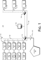
- Fig. 1 is a schematic illustration of various components of a power system, according to embodiments.
- a power system 100 may comprise one or more power sources 110 coupled to a shared electrical power bus 120 by one or more switchable connections 125.
- An interface 160 may be interposed between the power sources 110 and the connection 125.
- One or more loads 170 are coupled to the electrical power bus 120 also by a switchable connection 125.
- a communion network comprising a communication bus 132, and one or more routers 134 provides a communication link between a control system 150 and the various interfaces 160 and loads 170.
- Routers 134 serve to route communication messages, e.g., regarding power conditioning and quality management functions, between the various elements of communication network 130.
- the routers 134 may provide a presence on the network where the controller can selectively address each load switch and interface switch to configure the power network.
- the system 100 may be connected to an external utility grid 180 via a switchable connection 125.
- the power sources 110 may include one or more solar panel sources 110A, a combined heat/power source 110B, one or more wind turbines 110C, one or more generators 110D, and one or more power storage devices 110E.
- Power sources 110A-110E may be referred to collectively herein by the reference numeral 110.
- Interfaces 160 provide a power conditioning and quality management function.
- Fig. 2 is a schematic illustration of various components of an interface 160, according to embodiments. Referring briefly to Fig. 2 , in some embodiments the interfaces 160 comprise a power inverter 162, a power regulator 164, and a measurement system 166.
- the power inverter 162 transforms direct current (dc) power into a quasi-sinusoidal or pure sine wave generator alternating current (ac) power.
- the input to power inverter represents the total energy harvested or stored from the power source 110.
- a dc input may be a clean signal coming from the power source 110 which can range from 100Vdc to 200Vdc.
- the power inverter may comprise a sine wave generator, the output frequency of which is phased-locked to the output power frequency, while the amplitude is referenced to the power output when operating as a slave.
- the output may be set as a voltage source which is referenced from the dc fixed voltage generator and the frequency of which is referenced from the quasi-sinusoidal waveform generator.
- the power regulator 164 regulates the output power at the interface when connected to linear and non-linear loads, and during overload and under-load conditions. Power regulator 164 may also include compensators to help balance the line due to destabilizing effects of reactive elements and transients.
- the measurement system 166 acts as "net metering" module when the system 100 is coupled to the utility grid 180.
- the power interfaces 160 see an infinite load and an ideal constant voltage source.
- each power source 110 operates at maximum point power transfer (MPPT).
- MPPT maximum point power transfer
- a more complex power algorithm may be used to achieve MPPT and to accurately supply local loads first, then shared loads second or vice versa.
- the measurement system 166 continuously monitors and performs measurements on the energy harvest, energy forecasted, local loads, and shared load demands for the system 100.
- the overall system ischemic load demands may be determined in real time, as well as the overall available shared power available. When necessary, or when the available forecasted power available is less than the overall load demand; the power system 100 can prioritize loads depending on the relative importance of the load. Less important loads may be disconnected or may have a maximum power limit available.
- the communication network 130 may be a local area network (LAN).
- the controller 150, each interface 160 and each load 170 may be coupled to the LAN 130 and each may be assigned a unique network node identifier, e.g., in an internet protocol (IP) network each node may be assigned an IP address.
- IP internet protocol
- the IP addresses of the various network nodes may be openly addressable by entities outside the system 100, while in other embodiments the IP addresses of the various network nodes may be maintained within the system 100.
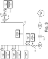
- Fig. 3 is a quasi-geographical schematic illustration of various components of a power system, according to embodiments.
- the embodiment depicted in Fig. 3 illustrates three loads 170 coupled directly to shared electrical bus 120 and a fourth load 170 coupled to the shared bus 120 via transmission lines 122 and transformers 124.
- the various input power sources are indicated by reference numerals 110.
- a 30 KW distributed energy resource (DER) coupled to the shared power bus 120 may be located physically proximate to the first load 170.
- second and third loads 170 and second and third 30 KW DER 170 are coupled to the shared electrical bus 120.
- An energy storage device 110 is coupled to the shared electrical bus 120 and a diesel generator 110 is selectively connectable to the shared electrical bus 120 via a switchable connection 125.
- the shared utility electrical bus 120 is coupled to the utility grid 180 via switched connection 125.
- One or more transformers 124 and a PCC (Point of Common Contact) 128 may be interposed between the switchable connection 125 and the utility grid 180.
- a power meter 127 may be included to meter power drawn by the system 100.
- Fig. 4 is a flowchart illustrating operations in a method to manage a microgrid coupled to a shared electrical grid, according to embodiments. Referring to Fig. 4 , the controller 150 initializes the communication network 130 at operation 410. In some examples the controller controller 150 may configure the IP addresses of the network nodes associated with the various elements of the system 100.
- all elements of the system 100 are coupled to the communication network 130.
- the network nodes for the elements of the system 100 may have access to the Internet except through a common redundant port controlled by the LAN.
- the failure of a single element failure will not disable other elements of the network from operating.
- Internet access to the LAN may be encrypted and secured, and no control elements can be accessed from the Internet; only status and measurement information are accessible. In other embodiments status and measurement information may also be encrypted.
- the controller 150 determines the grid configuration.
- the controller 150 may determine the energy consumed by each load 170, either directly or by communicating with a local controller coupled to the load 170.
- the controller 150 may distinguish local loads, i.e., loads that are to be supplied by local power sources, from shared loads, i.e., loads that are to be supplied by remote power sources or from the power grid 180 in operation 420.
- the controller 150 may also forecast power consumption by the respective loads 170 and power generation capabilities of the respective power sources 110.
- the controller 150 may assign a prioritization scheme to the load demands from the various loads 170.
- some loads 170 may be considered critical and may be entitled to a maximum power input before power may be directed to another load 170.
- Other loads may be designated as secondary, entitled to power only when available.
- the controller regulates power draw according to the prioritization scheme(s) established in operation 425.
- the controller monitor 150 may communicate with the interface 160 to monitor power outputs from the various input power sources 110.
- the controller 150 may monitor the power loads 170 coupled to the electrical power bus 120, and regulate the power drawn from one or more of the input power sources to the at least one electrical power bus 120 in accordance with the prioritization scheme(s).
- the controller may selectively disconnect a power load 170 from the network, and/or add another input power source 110 to the network.
- the controller 150 may completely disconnect a power source 110 from the electrical power bus 120, e.g., by switching the switchable connection 125 between a first state in which an electrical connection is established between the at least one input power source 110 and the at least one electrical power bus 120 and a second state in which an electrical connection is severed between the at least one input power source 110 and the at least one electrical power bus 120.
- measurement system 166 in the interface 160 monitors a power requirement of one or more loads coupled to the electrical power bus 120, and manages the at least one power regulator 164 to draw a predetermined amount of power from the at least one input power source 110.
- the controller 150 may include a system health management operation that monitors every smart elements of the network to aid in the maintenance and to aid in the real-time graceful degradation of the system during its lifetime. Also, the software of command and control can be loaded into any power interfaces 160 to provide redundancy.
- Fig. 5 is a schematic illustration of a computing system 500 that may be used in conjunction with a system 100.
- system 500 includes a computing device 508 and one or more accompanying input/output devices including a display 502 having a screen 504, one or more speakers 506, a keyboard 510, one or more other I/O device(s) 512, and a mouse 514.
- the other I/O device(s) 512 may include a touch screen, a voice-activated input device, a track ball, and any other device that allows the system 500 to receive input from a user.
- the computing device 508 includes system hardware 520 and memory 530, which may be implemented as random access memory and/or read-only memory.
- a file store 580 may be communicatively coupled to computing device 508.
- File store 580 may be internal to computing device 508 such as, e.g., one or more hard drives, CD-ROM drives, DVD-ROM drives, or other types of storage devices.
- File store 580 may also be external to computer 508 such as, e.g., one or more external hard drives, network attached storage, or a separate storage network.
- System hardware 520 may include one or more processors 522, video controllers 524, network interfaces 526, and bus structures 528.
- processor 522 may be embodied as an Intel ® Pentium IV® processor available from Intel Corporation, Santa Clara, California, USA.
- processor means any type of computational element, such as but not limited to, a microprocessor, a microcontroller, a complex instruction set computing (CISC) microprocessor, a reduced instruction set (RISC) microprocessor, a very long instruction word (VLIW) microprocessor, or any other type of processor or processing circuit.
- CISC complex instruction set computing
- RISC reduced instruction set
- VLIW very long instruction word
- Graphics controller 524 may function as an adjunction processor that manages graphics and/or video operations. Graphics controller 524 may be integrated onto the motherboard of computing system 500 or may be coupled via an expansion slot on the motherboard.
- network interface 526 could be a wired interface such as an Ethernet interface (see, e.g., Institute of Electrical and Electronics Engineers/IEEE 802.3-2002) or a wireless interface such as an IEEE 802.11a, b or g-compliant interface (see, e.g., IEEE Standard for IT-Telecommunications and information exchange between systems LAN/MAN--Part II: Wireless LAN Medium Access Control (MAC) and Physical Layer (PHY) specifications Amendment 4: Further Higher Data Rate Extension in the 2.4 GHz Band, 802.11G-2003).
- GPRS general packet radio service
- Bus structures 528 connect various components of system hardware 528.
- bus structures 528 may be one or more of several types of bus structure(s) including a memory bus, a peripheral bus or external bus, and/or a local bus using any variety of available bus architectures including, but not limited to, 11-bit bus, Industrial Standard Architecture (ISA), MicroChannel Architecture (MSA), Extended ISA (EISA), Intelligent Drive Electronics (IDE), VESA Local Bus (VLB), Peripheral Component Interconnect (PCI), Universal Serial Bus (USB), Advanced Graphics Port (AGP), Personal Computer Memory Card International Association bus (PCMCIA), and Small Computer Systems Interface (SCSI).
- ISA Industrial Standard Architecture
- MSA MicroChannel Architecture
- EISA Extended ISA
- IDE Intelligent Drive Electronics
- VLB VESA Local Bus
- PCI Peripheral Component Interconnect
- USB Universal Serial Bus
- AGP Advanced Graphics Port
- PCMCIA Personal Computer Memory Card International Association bus
- SCSI Small Computer Systems Interface
- Memory 530 may include an operating system 540 for managing operations of computing device 508.
- operating system 540 includes a hardware interface module 554 that provides an interface to system hardware 520.
- operating system 540 may include a file system 550 that manages files used in the operation of computing device 508 and a process control subsystem 552 that manages processes executing on computing device 508.
- memory module 530 may comprise a system management module 562 to implement the power management operations described with reference to Fig. 4 , and a health management module 564 to implement health management functions.
- Operating system 540 may include (or manage) one or more communication interfaces 544 that may operate in conjunction with system hardware 520 to transceive data packets and/or data streams from a remote source. Operating system 540 may further include a system call interface module 542 that provides an interface between the operating system 540 and one or more application modules resident in memory 530. Operating system 540 may be embodied as a UNIX operating system or any derivative thereof (e.g., Linux, Solaris, etc.) or as a Windows® brand operating system, or other operating systems.
- a controller to manage operations of a smartgrid system comprising logic to: monitor power outputs from at least one input power source; monitor one or more power loads coupled to the smartgrid system; and regulate the power drawn from one or more of the input power sources to the smartgrid system.
- the controller further comprises: at least one electrical power bus connectable to the at least one input power source by one or more switchable connections; and a communication network coupled to the smart microgrid system.
- the communication network comprises at least one router, and wherein the controller manages one or more operations of the router.
- the controller comprises logic to: initialize the communication network coupled to the smart microgrid system; determine a grid configuration for the at least one input power source; determine an average shared loading and an average local load; and perform a state of health check routine for the at least one input power source.
Landscapes
- Engineering & Computer Science (AREA)
- Power Engineering (AREA)
- Remote Monitoring And Control Of Power-Distribution Networks (AREA)
- Supply And Distribution Of Alternating Current (AREA)
- Direct Current Feeding And Distribution (AREA)
Claims (19)
- Système de microréseau intelligent (100), comprenant :au moins un bus de puissance électrique (120) qui peut être connecté à au moins une source de puissance d'entrée (110) par une ou plusieurs connexions commutables (125) ;un réseau de communication (130) couplé au système de microréseau intelligent ; etun contrôleur (150) couplé au réseau de communication, dans lequel le contrôleur comprend une logique pour :surveiller des rendements de sortie de puissance en provenance de l'au moins une source de puissance d'entrée ;surveiller une ou plusieurs charges de puissance couplées à l'au moins un bus de puissance électrique ; etréguler la puissance extraite d'une une ou plusieurs des sources de puissance d'entrée vers l'au moins un bus de puissance électrique ;dans lequel le bus de puissance électrique est couplé à un réseau électrique externe (180) via une connexion commutée de telle sorte que le système peut fonctionner dans un mode rattaché au réseau ou un mode de réseau isolé.
- Système (100) selon la revendication 1, dans lequel l'au moins une source de puissance d'entrée (110) comprend au moins l'un parmi :une source de puissance solaire (110A) ;une source de puissance calorifique combinée (110B);une éolienne (110C);un générateur de combustion (110D); ouun dispositif de stockage de puissance (110E).
- Système (100) selon la revendication 1, dans lequel le contrôleur (150) commute les une ou plusieurs connexions commutables (125) entre :
un premier état dans lequel une connexion électrique est établie entre l'au moins une source de puissance d'entrée (110) et l'au moins un bus de puissance électrique (120) et :
un second état dans lequel une connexion électrique est coupée entre l'au moins une source de puissance d'entrée et l'au moins un bus de puissance électrique. - Système (100) selon la revendication 1, comprenant en outre au moins une interface de bus de puissance (160), dans lequel chaque interface de bus de puissance comprend :au moins un convertisseur de puissance (162) ;au moins un régulateur de puissance (164) ; etau moins un système de mesure (166).
- Système (100) selon la revendication 4, dans lequel le convertisseur de puissance (162) transforme une puissance à courant continu générée par une source de puissance en une puissance électrique à courant alternatif.
- Système (100) selon la revendication 4, dans lequel le régulateur de puissance (164) régule la puissance de sortie en provenance de l'au moins une source de puissance d'entrée (110) au niveau de l'interface de bus de puissance (160).
- Système (100) selon la revendication 4, dans lequel l'au moins un système de mesure (166) comprend une logique pour
surveiller un impératif de puissance d'une ou plusieurs charges (170) couplées au bus de puissance électrique (120) ; et
gérer l'au moins un régulateur de puissance (164) pour extraire une quantité prédéterminée de puissance de l'au moins une source de puissance d'entrée. - Système (100) selon la revendication 4, dans lequel l'interface de bus de puissance (160) synchronise un ou plusieurs paramètres électriques de puissance générés par l'au moins une source de puissance d'entrée (110) avec des paramètres électriques d'électricité sur l'au moins un bus de puissance électrique (120).
- Système (100) selon la revendication 4, dans lequel le système de mesure (166) :surveille des données de puissance incluant un captage d'énergie, des charges locales prévues et des charges partagées pour l'au moins une source de puissance d'entrée (110); ettransfère les données de puissance à l'au moins un régulateur de puissance (164).
- Système (100) selon la revendication 1, dans lequel le contrôleur (150) comprend en outre une logique pour :initialiser le réseau de communication (130) couplé au système de microréseau intelligent ;déterminer une configuration de réseau pour l'au moins une source de puissance d'entrée (110) ;déterminer un chargement partagé moyen et une charge locale moyenne ; etréaliser une routine de vérification d'état de santé pour l'au moins une source de puissance d'entrée.
- Système (100) selon la revendication 1, dans lequel le contrôleur (150) comprend en outre une logique pour :assigner une ou plusieurs sources de puissance d'entrée (110) en tant que source de puissance principale et une ou plusieurs sources de puissance d'entrée en tant que source de puissance secondaire à une charge donnée (170) ; etprioriser une ou plusieurs charges dans l'éventualité d'une pénurie de puissance, la priorité d'une charge particulière étant utilisée pour déconnecter sélectivement la charge particulière du bus de puissance électrique (120) par le biais d'une connexion commutable (125).
- Procédé pour gérer un ou plusieurs microréseaux couplés à un réseau électrique partagé (100), le procédé comprenant :la mesure d'une ou plusieurs charges locales sur les un ou plusieurs microréseaux ;la mesure d'une ou plusieurs charges partagées sur le réseau électrique partagé ;l'assignation (425) d'un modèle de priorisation aux une ou plusieurs charges locales et aux une ou plusieurs charges partagées ;la régulation (430) de la puissance extraite des un ou plusieurs microréseaux vers le réseau électrique partagé conformément au modèle de priorisation ;le couplage du réseau électrique partagé à un réseau électrique externe (180) via une connexion commutée (125) ; etla mise en service du réseau électrique partagé dans un mode rattaché au réseau ou un mode de réseau isolé.
- Procédé selon la revendication 12, comprenant en outre :
l'initialisation (410) d'un réseau de communication (130) couplé aux un ou plusieurs microréseaux et au réseau électrique partagé (100). - Procédé selon la revendication 12, dans lequel la régulation (430) de la puissance extraite des un ou plusieurs microréseaux vers le réseau électrique partagé (100) conformément au modèle de priorisation comprend la déconnexion sélective des un ou plusieurs microréseaux du réseau électrique partagé conformément au modèle de priorisation.
- Procédé selon la revendication 12, dans lequel la régulation (430) de la puissance extraite des un ou plusieurs microréseaux vers le réseau électrique partagé (100) conformément au modèle de priorisation comprend la conversion d'au moins une propriété électrique de la puissance extraite des un ou plusieurs microréseaux.
- Procédé selon la revendication 12, dans lequel la régulation (430) de la puissance extraite des un ou plusieurs microréseaux vers le réseau électrique partagé (100) conformément au modèle de priorisation comprend :la mesure d'un impératif de puissance d'une ou plusieurs charges (170) couplées au réseau électrique partagé : etla gestion au niveau d'un régulateur de puissance (164) pour extraire une quantité prédéterminée de puissance des un ou plusieurs microréseaux.
- Procédé selon la revendication 12, dans lequel la régulation (430) de la puissance extraite des un ou plusieurs microréseaux vers le réseau électrique partagé (100) conformément au modèle de priorisation comprend la synchronisation d'un ou plusieurs paramètres électriques de puissance générés par l'au moins un microréseau avec des paramètres électriques d'électricité sur au moins un bus de puissance électrique (120).
- Procédé selon la revendication 12, dans lequel la régulation (430) de la puissance extraite des un ou plusieurs microréseaux vers le réseau électrique partagé (100) conformément au modèle de priorisation comprend :la surveillance de données de puissance incluant un captage d'énergie, des charges locales prévues et des charges partagées pour l'au moins un microréseau ; etle transfert des données de puissance à l'au moins un régulateur de puissance (164).
- Procédé selon la revendication 12, comprenant en outre la réalisation d'une routine de vérification d'état de santé.
Applications Claiming Priority (1)
| Application Number | Priority Date | Filing Date | Title |
|---|---|---|---|
| US12/897,664 US9240687B2 (en) | 2010-10-04 | 2010-10-04 | Smart microgrid |
Publications (3)
| Publication Number | Publication Date |
|---|---|
| EP2437372A2 EP2437372A2 (fr) | 2012-04-04 |
| EP2437372A3 EP2437372A3 (fr) | 2017-10-04 |
| EP2437372B1 true EP2437372B1 (fr) | 2019-12-04 |
Family
ID=44862517
Family Applications (1)
| Application Number | Title | Priority Date | Filing Date |
|---|---|---|---|
| EP11183838.9A Active EP2437372B1 (fr) | 2010-10-04 | 2011-10-04 | Microgrille intelligente |
Country Status (3)
| Country | Link |
|---|---|
| US (1) | US9240687B2 (fr) |
| EP (1) | EP2437372B1 (fr) |
| JP (1) | JP6029270B2 (fr) |
Cited By (1)
| Publication number | Priority date | Publication date | Assignee | Title |
|---|---|---|---|---|
| EP4478574A3 (fr) * | 2023-06-14 | 2025-01-15 | Honeywell International Inc. | Système et procédé de gestion et de commande d'énergie de micro-réseaux |
Families Citing this family (78)
| Publication number | Priority date | Publication date | Assignee | Title |
|---|---|---|---|---|
| US20120068534A1 (en) * | 2009-11-22 | 2012-03-22 | Yang Pan | Power Supply System Including Alternative Sources-Control and Communication |
| US9660451B1 (en) * | 2010-11-29 | 2017-05-23 | Sunpower Corporation | Islanded operation of distributed power sources |
| US9281690B2 (en) * | 2010-12-21 | 2016-03-08 | Palo Alto Research Center Incorporated | Tactical smart grids |
| KR20120070903A (ko) * | 2010-12-22 | 2012-07-02 | 한국전자통신연구원 | 스마트그리드 전력제어장치 및 그를 이용한 전력 제어방법 |
| US8831788B2 (en) * | 2011-04-20 | 2014-09-09 | General Electric Company | Systems, methods, and apparatus for maintaining stable conditions within a power grid |
| CN102170134B (zh) * | 2011-05-05 | 2013-03-06 | 许继集团有限公司 | 微电网并网到离网控制方法及无缝切换方法 |
| CN202059185U (zh) * | 2011-05-05 | 2011-11-30 | 许继集团有限公司 | 微电网并离网控制装置 |
| US11901810B2 (en) * | 2011-05-08 | 2024-02-13 | Koolbridge Solar, Inc. | Adaptive electrical power distribution panel |
| US9207735B2 (en) | 2011-08-02 | 2015-12-08 | Gram Power, Inc. | Power management device and system |
| US10935948B2 (en) | 2011-08-02 | 2021-03-02 | Synaptic Power Inc. | System and method for managing interactions between a plurality of devices |
| WO2013016811A1 (fr) | 2011-08-02 | 2013-02-07 | Synaptic Power Inc. | Système et procédé de commande d'une pluralité de dispositifs |
| US9455572B2 (en) * | 2012-04-27 | 2016-09-27 | Marvin A Motsenbocker | Voltage prioritization of solar loads |
| KR101354895B1 (ko) * | 2012-06-01 | 2014-01-23 | 엘에스산전 주식회사 | 전력 감시 시스템 및 전력 시스템 정보 디스플레이 방법 |
| ES2586954T3 (es) * | 2012-06-07 | 2016-10-19 | Grupo Guascor S.L. | Sistema de reparto de carga |
| CN102810877A (zh) * | 2012-08-21 | 2012-12-05 | 湖南大学 | 一种微网调控一体化的方法 |
| US10289080B2 (en) | 2012-10-11 | 2019-05-14 | Flexgen Power Systems, Inc. | Multi-generator applications using variable speed and solid state generators for efficiency and frequency stabilization |
| US9312699B2 (en) | 2012-10-11 | 2016-04-12 | Flexgen Power Systems, Inc. | Island grid power supply apparatus and methods using energy storage for transient stabilization |
| CN102916448A (zh) * | 2012-11-16 | 2013-02-06 | 宁夏银星能源光伏发电设备制造有限公司 | 一种蜂窝式智能集中控制的分布式多能源发电系统 |
| US20140229031A1 (en) * | 2013-02-14 | 2014-08-14 | Petra Solar, Inc. | Micro-Inverter Based AC-Coupled Photovoltaic Microgrid System with Wireless Smart-Grid Controls |
| EP2959561A4 (fr) * | 2013-02-19 | 2016-09-14 | Solantro Semiconductor Corp | Miniréseaux à autoformation |
| US9553517B2 (en) | 2013-03-01 | 2017-01-24 | Fllexgen Power Systems, Inc. | Hybrid energy storage system and methods |
| WO2014185035A1 (fr) | 2013-05-17 | 2014-11-20 | 日本電気株式会社 | Système de réseau de puissance et dispositif ainsi que procédé de réglage de puissance |
| JP6158628B2 (ja) * | 2013-07-29 | 2017-07-05 | 京セラ株式会社 | 電源機器判定装置、電源機器判定方法及び電力変換装置 |
| CN103515980A (zh) * | 2013-08-01 | 2014-01-15 | 国家电网公司 | 含地源热泵的微电网能量管理方法 |
| KR101488675B1 (ko) * | 2013-09-02 | 2015-02-11 | 한국에너지기술연구원 | 전력변환 시스템을 제어하는 장치 및 방법 |
| CN103532158B (zh) * | 2013-10-28 | 2016-01-20 | 浙江南都电源动力股份有限公司 | 一种微网新能源混合储能系统 |
| GB2519755A (en) * | 2013-10-29 | 2015-05-06 | Bae Systems Plc | Controlling power distribution with a microgrid |
| GB2519754A (en) * | 2013-10-29 | 2015-05-06 | Bae Systems Plc | Operating a microgrid |
| KR101582097B1 (ko) * | 2013-11-08 | 2016-01-05 | 한국에너지기술연구원 | 독립전력시스템, 제어장치 및 수급 상태를 표시하는 콘센트장치 |
| KR101506237B1 (ko) * | 2013-11-08 | 2015-03-27 | 한국에너지기술연구원 | 독립전력시스템, 제어장치 및 공급가능전력을 표시하는 콘센트장치 |
| JP2015139256A (ja) * | 2014-01-21 | 2015-07-30 | 公立大学法人大阪市立大学 | 直接中継型電力パケット配電ネットワーク |
| WO2015110158A1 (fr) * | 2014-01-23 | 2015-07-30 | Nec Europe Ltd. | Procédé de commande de l'équilibrage de charge au sein d'un système de distribution d'énergie, et système de distribution d'énergie correspondant |
| CN103825279B (zh) * | 2014-02-21 | 2015-11-04 | 华南理工大学 | 基于鲁棒控制的微电网系统电压稳定控制方法 |
| CN104901578B (zh) * | 2014-03-07 | 2017-10-27 | 长沙理工大学 | 分布式光伏电源单相柔性串并联功率接口 |
| CN103872775B (zh) * | 2014-03-13 | 2016-01-27 | 中国能源建设集团广东省电力设计研究院有限公司 | 一种智能微网监控系统及监控方法 |
| KR101516802B1 (ko) * | 2014-05-16 | 2015-05-04 | 케이씨코트렐 주식회사 | 독립형 마이크로그리드용 배전반 |
| CN104092306A (zh) * | 2014-07-14 | 2014-10-08 | 国网上海市电力公司 | 110千伏变电站微网控制系统 |
| US9923371B1 (en) * | 2014-08-13 | 2018-03-20 | Rosendin Electric, Inc. | Shared resource system |
| CN105528466B (zh) * | 2014-09-28 | 2019-04-05 | 国家电网公司 | 考虑电力系统适应性和经济性的风电优化规划建模方法 |
| CN107534294B (zh) | 2014-12-30 | 2021-07-30 | 弗莱斯金电力系统公司 | 具有有功和无功功率控制的暂态功率稳定化设备 |
| ES2748178T3 (es) | 2015-03-10 | 2020-03-13 | Abb Schweiz Ag | Aparato convertidor CC/CA configurable como conectado a la red o independiente y sistema de conversión y generación de energía que comprende dicho aparato convertidor CC/CA |
| CN106208341A (zh) * | 2016-08-01 | 2016-12-07 | 云南电网有限责任公司曲靖供电局 | 一种终端变电站主电源或主变压器故障导致全站失压的母线快速自愈方法 |
| US11455021B2 (en) * | 2016-08-18 | 2022-09-27 | Cato | Datacenter power management using AC and DC power sources |
| US10587118B2 (en) | 2016-11-15 | 2020-03-10 | Solaredge Technologies Ltd. | Smart outlet |
| ES2813954T3 (es) * | 2017-01-05 | 2021-03-25 | Ferroamp Elektronik Ab | Disposición de red de energía local |
| CN107067146B (zh) * | 2017-01-09 | 2021-01-22 | 国网浙江省电力有限公司经济技术研究院 | 考虑热负荷二维可控性的微网热电协调调度方法 |
| US10199860B2 (en) | 2017-01-28 | 2019-02-05 | Microsoft Technology Licensing, Llc | Power supply recovery current history-based limitation |
| CN109386429B (zh) * | 2017-08-04 | 2021-01-15 | 中国电力科学研究院 | 一种风电与光热发电互补系统协调运行控制方法与装置 |
| CN107591844B (zh) * | 2017-09-22 | 2020-07-31 | 东南大学 | 考虑节点注入功率不确定性的主动配电网鲁棒重构方法 |
| EP4148942B1 (fr) * | 2017-09-28 | 2024-06-19 | Huawei Technologies Co., Ltd. | Procédé de synchronisation des signaux de contrôle pwm des onduleurs, onduleur et système de réseau électrique |
| US11322942B2 (en) | 2017-10-12 | 2022-05-03 | Schlumberger Technology Corporation | Electrical power generation and distribution system with power recovery and regeneration |
| CN107623323A (zh) * | 2017-10-17 | 2018-01-23 | 酒泉职业技术学院 | 一种需求侧响应下微电网运行策略 |
| US11735950B2 (en) | 2017-10-27 | 2023-08-22 | Schlumberger Technology Corporation | Supplemental power unit for drilling rig |
| US11050377B2 (en) | 2017-10-30 | 2021-06-29 | Schlumberger Technology Corporation | Systems and methods for managing drive parameters after maintenance |
| US10920562B2 (en) | 2017-11-01 | 2021-02-16 | Schlumberger Technology Corporation | Remote control and monitoring of engine control system |
| US11264801B2 (en) | 2018-02-23 | 2022-03-01 | Schlumberger Technology Corporation | Load management algorithm for optimizing engine efficiency |
| US11581725B2 (en) | 2018-07-07 | 2023-02-14 | Intelesol, Llc | Solid-state power interrupters |
| US11349296B2 (en) | 2018-10-01 | 2022-05-31 | Intelesol, Llc | Solid-state circuit interrupters |
| US10804736B2 (en) * | 2018-11-13 | 2020-10-13 | Mitsubishi Electric Research Laboratories, Inc. | Methods and systems for post-disaster resilient restoration of power distribution system |
| US11170964B2 (en) | 2019-05-18 | 2021-11-09 | Amber Solutions, Inc. | Intelligent circuit breakers with detection circuitry configured to detect fault conditions |
| WO2020236423A1 (fr) | 2019-05-23 | 2020-11-26 | Schlumberger Technology Corporation | Réglages dynamiques pour commande de démarrage-arrêt automatique dépendant de la charge de génératrice |
| CN112290530B (zh) * | 2019-07-25 | 2022-09-27 | 南京理工大学 | 风储联合发电商参与能量-调频市场的投标策略优化方法 |
| US11514383B2 (en) | 2019-09-13 | 2022-11-29 | Schlumberger Technology Corporation | Method and system for integrated well construction |
| CN110601261B (zh) * | 2019-09-18 | 2021-03-05 | 浙江大学 | 基于感控逻辑的微网控制器业务逻辑一致性分析方法 |
| US11920438B2 (en) | 2019-10-17 | 2024-03-05 | Schlumberger Technology Corporation | Intelligent power management system |
| US12392225B2 (en) | 2020-03-31 | 2025-08-19 | Schlumberger Technology Corporation | Power management at a wellsite |
| US11268350B2 (en) | 2020-04-03 | 2022-03-08 | Schlumberger Technology Corporation | Intelligent energy management system of a drilling rig |
| US12021381B2 (en) | 2020-05-26 | 2024-06-25 | University Of Manitoba | Device for electrically interconnecting DC microgrid with higher voltage DC bus and related methods |
| CN111628525B (zh) * | 2020-05-29 | 2022-03-08 | 辽宁工业大学 | 基于切换系统的微电网双模式稳定控制方法 |
| WO2022036016A1 (fr) * | 2020-08-11 | 2022-02-17 | Amber Solutions, Inc. | Système de commande intelligent de sélection et de surveillance de source d'énergie |
| US11697986B2 (en) | 2020-09-04 | 2023-07-11 | Schlumberger Technology Corporation | Power management at a wellsite |
| US11456601B1 (en) * | 2021-08-08 | 2022-09-27 | D&D Patent And Trademark Holding Company, Llc | Intelligent routing of electricity |
| US12113525B2 (en) | 2021-09-30 | 2024-10-08 | Amber Semiconductor, Inc. | Intelligent electrical switches |
| US12348028B2 (en) | 2021-10-22 | 2025-07-01 | Amber Semiconductor, Inc. | Multi-output programmable power manager |
| US12051897B2 (en) | 2021-12-20 | 2024-07-30 | Schlumberger Technology Corporation | Power management at a wellsite |
| US11942781B2 (en) * | 2021-12-20 | 2024-03-26 | Schlumberger Technology Corporation | Power management at a wellsite |
| US12362646B2 (en) | 2022-01-26 | 2025-07-15 | Amber Semiconductor, Inc. | Controlling AC power to inductive loads |
| DE102023207826A1 (de) * | 2023-08-15 | 2025-02-20 | Siemens Energy Global GmbH & Co. KG | Regelung im Inselnetz |
Citations (2)
| Publication number | Priority date | Publication date | Assignee | Title |
|---|---|---|---|---|
| WO2008029711A1 (fr) * | 2006-09-05 | 2008-03-13 | Toshiba Carrier Corporation | Dispositif onduleur séquentiel |
| US20080278000A1 (en) * | 2005-03-01 | 2008-11-13 | Capp F William | Methods and Systems for Intentionally Isolating Distributed Power Generation Sources |
Family Cites Families (14)
| Publication number | Priority date | Publication date | Assignee | Title |
|---|---|---|---|---|
| US6816466B1 (en) * | 2000-06-02 | 2004-11-09 | Astec International Limited | Automatic module configuration in a telecommunications power system |
| US20020036430A1 (en) * | 2000-09-28 | 2002-03-28 | Welches Richard S. | Local area grid for distributed power |
| NZ535509A (en) * | 2002-03-28 | 2006-03-31 | Robertshaw Controls Co | Energy management system and method |
| EP1525656A1 (fr) * | 2002-06-23 | 2005-04-27 | Powerlynx A/S | Convertisseur de puissance |
| JP2007510394A (ja) * | 2003-10-24 | 2007-04-19 | スクエア・ディー・カンパニー | インテリジェントな電力管理制御システム |
| US7183667B2 (en) * | 2003-12-19 | 2007-02-27 | Square D Company | Method and apparatus for power inverter synchronization |
| US7687937B2 (en) * | 2005-03-18 | 2010-03-30 | Wisconsin Alumni Research Foundation | Control of small distributed energy resources |
| JP2008043170A (ja) | 2006-08-10 | 2008-02-21 | Nippon Telegr & Teleph Corp <Ntt> | 電力供給システム、需用家群設備、およびその監視制御方法 |
| JP2008104269A (ja) | 2006-10-18 | 2008-05-01 | Toho Gas Co Ltd | マイクログリッドの需給管理システム |
| US7983799B2 (en) * | 2006-12-15 | 2011-07-19 | General Electric Company | System and method for controlling microgrid |
| JP2008271625A (ja) | 2007-04-16 | 2008-11-06 | Chugoku Electric Power Co Inc:The | 電力系統遮断システム、方法及びプログラム |
| BRPI0810747B1 (pt) * | 2007-05-08 | 2023-10-10 | Schneider Electric It Corporation | Sistema conversor de energia e e métodos de regulação da liberação de energia por sistema de liberação de energia |
| WO2011027339A1 (fr) * | 2009-09-03 | 2011-03-10 | Meishar Immediate Community (Mic) Ltd. | Procédés et systèmes pour gérer la distribution et le commerce d'électricité |
| US9058037B2 (en) * | 2009-12-22 | 2015-06-16 | General Electric Company | Return of appliance state after demand response event |
-
2010
- 2010-10-04 US US12/897,664 patent/US9240687B2/en active Active
-
2011
- 2011-09-27 JP JP2011210246A patent/JP6029270B2/ja active Active
- 2011-10-04 EP EP11183838.9A patent/EP2437372B1/fr active Active
Patent Citations (2)
| Publication number | Priority date | Publication date | Assignee | Title |
|---|---|---|---|---|
| US20080278000A1 (en) * | 2005-03-01 | 2008-11-13 | Capp F William | Methods and Systems for Intentionally Isolating Distributed Power Generation Sources |
| WO2008029711A1 (fr) * | 2006-09-05 | 2008-03-13 | Toshiba Carrier Corporation | Dispositif onduleur séquentiel |
Cited By (2)
| Publication number | Priority date | Publication date | Assignee | Title |
|---|---|---|---|---|
| EP4478574A3 (fr) * | 2023-06-14 | 2025-01-15 | Honeywell International Inc. | Système et procédé de gestion et de commande d'énergie de micro-réseaux |
| AU2024203106B2 (en) * | 2023-06-14 | 2025-09-18 | Honeywell International Inc. | System and method for the energy management and control of microgrids |
Also Published As
| Publication number | Publication date |
|---|---|
| US9240687B2 (en) | 2016-01-19 |
| EP2437372A2 (fr) | 2012-04-04 |
| EP2437372A3 (fr) | 2017-10-04 |
| JP6029270B2 (ja) | 2016-11-24 |
| JP2012085516A (ja) | 2012-04-26 |
| US20120080942A1 (en) | 2012-04-05 |
Similar Documents
| Publication | Publication Date | Title |
|---|---|---|
| EP2437372B1 (fr) | Microgrille intelligente | |
| US11056908B2 (en) | Uninterruptible power supply systems and methods using isolated interface for variably available power source | |
| Aamir et al. | Uninterruptible power supply (UPS) system | |
| EP2528181B1 (fr) | SYSTÈME D'ALIMENTATION ÉLECTRIQUE AVEC INTÉGRATION D'ÉNERGIE ÉOLIENNE, D'ÉNERGIE SOLAIRE, d' un générateur DIESEL ET D'ALIMENTATION SECTEUR | |
| CN102005817B (zh) | 基于微电网的不间断电源装置及其调度控制方法 | |
| US9568903B2 (en) | System and method for controlling states of a DC and AC BUS microgrid | |
| CN113131462A (zh) | 交流负荷供电系统和方法 | |
| US20130088084A1 (en) | Networklized DC Power System | |
| CN112117767B (zh) | 基于多站融合的供配电系统 | |
| KR20110068640A (ko) | 에너지 관리 시스템 및 이의 제어 방법 | |
| KR20180079769A (ko) | 배터리 시스템 | |
| CN115833210B (zh) | 一种多机并联储能系统及其充放电控制方法 | |
| CN104022527A (zh) | 直流微网系统 | |
| US12489359B2 (en) | Power supply and demand synchronization system and method for modular multi-port system | |
| CN111682569A (zh) | 一种智能控制的储能系统 | |
| CN110148933A (zh) | 多单元多母线直流微电网架构及分区分层智能控制系统 | |
| Stalling et al. | Design and evaluation of a universal power router for residential applications | |
| CN104795845A (zh) | 基于对等控制和集中控制相结合的独立微电网混合控制方法及系统 | |
| Saravanan et al. | Overview of microgrid systems | |
| US12407169B2 (en) | Energy coupling method and system for household energy storage | |
| CN203205969U (zh) | 基于can总线的多能源多模式不间断电源 | |
| CN118539526A (zh) | 一种基于240v直流架构的智慧型多源输入新能源控制系统 | |
| WO2024020011A1 (fr) | Systèmes et procédés de compensation de perte d'énergie sans charge d'un système de stockage d'énergie de batterie | |
| KR20200079606A (ko) | 부하 분산을 위한 dc ups 제어 시스템 | |
| CN117458597B (zh) | 一种基于交流组件的发电系统 |
Legal Events
| Date | Code | Title | Description |
|---|---|---|---|
| PUAI | Public reference made under article 153(3) epc to a published international application that has entered the european phase |
Free format text: ORIGINAL CODE: 0009012 |
|
| 17P | Request for examination filed |
Effective date: 20111004 |
|
| AK | Designated contracting states |
Kind code of ref document: A2 Designated state(s): AL AT BE BG CH CY CZ DE DK EE ES FI FR GB GR HR HU IE IS IT LI LT LU LV MC MK MT NL NO PL PT RO RS SE SI SK SM TR |
|
| AX | Request for extension of the european patent |
Extension state: BA ME |
|
| PUAL | Search report despatched |
Free format text: ORIGINAL CODE: 0009013 |
|
| AK | Designated contracting states |
Kind code of ref document: A3 Designated state(s): AL AT BE BG CH CY CZ DE DK EE ES FI FR GB GR HR HU IE IS IT LI LT LU LV MC MK MT NL NO PL PT RO RS SE SI SK SM TR |
|
| AX | Request for extension of the european patent |
Extension state: BA ME |
|
| RIC1 | Information provided on ipc code assigned before grant |
Ipc: H02J 13/00 20060101ALI20170829BHEP Ipc: H02J 3/06 20060101ALI20170829BHEP Ipc: H02J 3/38 20060101AFI20170829BHEP |
|
| STAA | Information on the status of an ep patent application or granted ep patent |
Free format text: STATUS: EXAMINATION IS IN PROGRESS |
|
| 17Q | First examination report despatched |
Effective date: 20181212 |
|
| GRAP | Despatch of communication of intention to grant a patent |
Free format text: ORIGINAL CODE: EPIDOSNIGR1 |
|
| STAA | Information on the status of an ep patent application or granted ep patent |
Free format text: STATUS: GRANT OF PATENT IS INTENDED |
|
| INTG | Intention to grant announced |
Effective date: 20190603 |
|
| GRAS | Grant fee paid |
Free format text: ORIGINAL CODE: EPIDOSNIGR3 |
|
| GRAA | (expected) grant |
Free format text: ORIGINAL CODE: 0009210 |
|
| STAA | Information on the status of an ep patent application or granted ep patent |
Free format text: STATUS: THE PATENT HAS BEEN GRANTED |
|
| AK | Designated contracting states |
Kind code of ref document: B1 Designated state(s): AL AT BE BG CH CY CZ DE DK EE ES FI FR GB GR HR HU IE IS IT LI LT LU LV MC MK MT NL NO PL PT RO RS SE SI SK SM TR |
|
| REG | Reference to a national code |
Ref country code: GB Ref legal event code: FG4D |
|
| REG | Reference to a national code |
Ref country code: CH Ref legal event code: EP |
|
| REG | Reference to a national code |
Ref country code: AT Ref legal event code: REF Ref document number: 1210622 Country of ref document: AT Kind code of ref document: T Effective date: 20191215 |
|
| REG | Reference to a national code |
Ref country code: DE Ref legal event code: R096 Ref document number: 602011063764 Country of ref document: DE |
|
| REG | Reference to a national code |
Ref country code: IE Ref legal event code: FG4D |
|
| REG | Reference to a national code |
Ref country code: NL Ref legal event code: MP Effective date: 20191204 |
|
| REG | Reference to a national code |
Ref country code: LT Ref legal event code: MG4D |
|
| PG25 | Lapsed in a contracting state [announced via postgrant information from national office to epo] |
Ref country code: ES Free format text: LAPSE BECAUSE OF FAILURE TO SUBMIT A TRANSLATION OF THE DESCRIPTION OR TO PAY THE FEE WITHIN THE PRESCRIBED TIME-LIMIT Effective date: 20191204 Ref country code: LT Free format text: LAPSE BECAUSE OF FAILURE TO SUBMIT A TRANSLATION OF THE DESCRIPTION OR TO PAY THE FEE WITHIN THE PRESCRIBED TIME-LIMIT Effective date: 20191204 Ref country code: FI Free format text: LAPSE BECAUSE OF FAILURE TO SUBMIT A TRANSLATION OF THE DESCRIPTION OR TO PAY THE FEE WITHIN THE PRESCRIBED TIME-LIMIT Effective date: 20191204 Ref country code: BG Free format text: LAPSE BECAUSE OF FAILURE TO SUBMIT A TRANSLATION OF THE DESCRIPTION OR TO PAY THE FEE WITHIN THE PRESCRIBED TIME-LIMIT Effective date: 20200304 Ref country code: NO Free format text: LAPSE BECAUSE OF FAILURE TO SUBMIT A TRANSLATION OF THE DESCRIPTION OR TO PAY THE FEE WITHIN THE PRESCRIBED TIME-LIMIT Effective date: 20200304 Ref country code: GR Free format text: LAPSE BECAUSE OF FAILURE TO SUBMIT A TRANSLATION OF THE DESCRIPTION OR TO PAY THE FEE WITHIN THE PRESCRIBED TIME-LIMIT Effective date: 20200305 Ref country code: LV Free format text: LAPSE BECAUSE OF FAILURE TO SUBMIT A TRANSLATION OF THE DESCRIPTION OR TO PAY THE FEE WITHIN THE PRESCRIBED TIME-LIMIT Effective date: 20191204 Ref country code: SE Free format text: LAPSE BECAUSE OF FAILURE TO SUBMIT A TRANSLATION OF THE DESCRIPTION OR TO PAY THE FEE WITHIN THE PRESCRIBED TIME-LIMIT Effective date: 20191204 |
|
| PG25 | Lapsed in a contracting state [announced via postgrant information from national office to epo] |
Ref country code: HR Free format text: LAPSE BECAUSE OF FAILURE TO SUBMIT A TRANSLATION OF THE DESCRIPTION OR TO PAY THE FEE WITHIN THE PRESCRIBED TIME-LIMIT Effective date: 20191204 Ref country code: RS Free format text: LAPSE BECAUSE OF FAILURE TO SUBMIT A TRANSLATION OF THE DESCRIPTION OR TO PAY THE FEE WITHIN THE PRESCRIBED TIME-LIMIT Effective date: 20191204 |
|
| PG25 | Lapsed in a contracting state [announced via postgrant information from national office to epo] |
Ref country code: AL Free format text: LAPSE BECAUSE OF FAILURE TO SUBMIT A TRANSLATION OF THE DESCRIPTION OR TO PAY THE FEE WITHIN THE PRESCRIBED TIME-LIMIT Effective date: 20191204 |
|
| PG25 | Lapsed in a contracting state [announced via postgrant information from national office to epo] |
Ref country code: RO Free format text: LAPSE BECAUSE OF FAILURE TO SUBMIT A TRANSLATION OF THE DESCRIPTION OR TO PAY THE FEE WITHIN THE PRESCRIBED TIME-LIMIT Effective date: 20191204 Ref country code: CZ Free format text: LAPSE BECAUSE OF FAILURE TO SUBMIT A TRANSLATION OF THE DESCRIPTION OR TO PAY THE FEE WITHIN THE PRESCRIBED TIME-LIMIT Effective date: 20191204 Ref country code: NL Free format text: LAPSE BECAUSE OF FAILURE TO SUBMIT A TRANSLATION OF THE DESCRIPTION OR TO PAY THE FEE WITHIN THE PRESCRIBED TIME-LIMIT Effective date: 20191204 Ref country code: EE Free format text: LAPSE BECAUSE OF FAILURE TO SUBMIT A TRANSLATION OF THE DESCRIPTION OR TO PAY THE FEE WITHIN THE PRESCRIBED TIME-LIMIT Effective date: 20191204 Ref country code: PT Free format text: LAPSE BECAUSE OF FAILURE TO SUBMIT A TRANSLATION OF THE DESCRIPTION OR TO PAY THE FEE WITHIN THE PRESCRIBED TIME-LIMIT Effective date: 20200429 |
|
| PG25 | Lapsed in a contracting state [announced via postgrant information from national office to epo] |
Ref country code: SM Free format text: LAPSE BECAUSE OF FAILURE TO SUBMIT A TRANSLATION OF THE DESCRIPTION OR TO PAY THE FEE WITHIN THE PRESCRIBED TIME-LIMIT Effective date: 20191204 Ref country code: IS Free format text: LAPSE BECAUSE OF FAILURE TO SUBMIT A TRANSLATION OF THE DESCRIPTION OR TO PAY THE FEE WITHIN THE PRESCRIBED TIME-LIMIT Effective date: 20200404 Ref country code: SK Free format text: LAPSE BECAUSE OF FAILURE TO SUBMIT A TRANSLATION OF THE DESCRIPTION OR TO PAY THE FEE WITHIN THE PRESCRIBED TIME-LIMIT Effective date: 20191204 |
|
| REG | Reference to a national code |
Ref country code: DE Ref legal event code: R097 Ref document number: 602011063764 Country of ref document: DE |
|
| REG | Reference to a national code |
Ref country code: AT Ref legal event code: MK05 Ref document number: 1210622 Country of ref document: AT Kind code of ref document: T Effective date: 20191204 |
|
| PLBE | No opposition filed within time limit |
Free format text: ORIGINAL CODE: 0009261 |
|
| STAA | Information on the status of an ep patent application or granted ep patent |
Free format text: STATUS: NO OPPOSITION FILED WITHIN TIME LIMIT |
|
| PG25 | Lapsed in a contracting state [announced via postgrant information from national office to epo] |
Ref country code: DK Free format text: LAPSE BECAUSE OF FAILURE TO SUBMIT A TRANSLATION OF THE DESCRIPTION OR TO PAY THE FEE WITHIN THE PRESCRIBED TIME-LIMIT Effective date: 20191204 |
|
| 26N | No opposition filed |
Effective date: 20200907 |
|
| PG25 | Lapsed in a contracting state [announced via postgrant information from national office to epo] |
Ref country code: SI Free format text: LAPSE BECAUSE OF FAILURE TO SUBMIT A TRANSLATION OF THE DESCRIPTION OR TO PAY THE FEE WITHIN THE PRESCRIBED TIME-LIMIT Effective date: 20191204 Ref country code: PL Free format text: LAPSE BECAUSE OF FAILURE TO SUBMIT A TRANSLATION OF THE DESCRIPTION OR TO PAY THE FEE WITHIN THE PRESCRIBED TIME-LIMIT Effective date: 20191204 Ref country code: AT Free format text: LAPSE BECAUSE OF FAILURE TO SUBMIT A TRANSLATION OF THE DESCRIPTION OR TO PAY THE FEE WITHIN THE PRESCRIBED TIME-LIMIT Effective date: 20191204 |
|
| PG25 | Lapsed in a contracting state [announced via postgrant information from national office to epo] |
Ref country code: IT Free format text: LAPSE BECAUSE OF FAILURE TO SUBMIT A TRANSLATION OF THE DESCRIPTION OR TO PAY THE FEE WITHIN THE PRESCRIBED TIME-LIMIT Effective date: 20191204 |
|
| REG | Reference to a national code |
Ref country code: CH Ref legal event code: PL |
|
| PG25 | Lapsed in a contracting state [announced via postgrant information from national office to epo] |
Ref country code: LU Free format text: LAPSE BECAUSE OF NON-PAYMENT OF DUE FEES Effective date: 20201004 Ref country code: MC Free format text: LAPSE BECAUSE OF FAILURE TO SUBMIT A TRANSLATION OF THE DESCRIPTION OR TO PAY THE FEE WITHIN THE PRESCRIBED TIME-LIMIT Effective date: 20191204 |
|
| REG | Reference to a national code |
Ref country code: BE Ref legal event code: MM Effective date: 20201031 |
|
| PG25 | Lapsed in a contracting state [announced via postgrant information from national office to epo] |
Ref country code: LI Free format text: LAPSE BECAUSE OF NON-PAYMENT OF DUE FEES Effective date: 20201031 Ref country code: CH Free format text: LAPSE BECAUSE OF NON-PAYMENT OF DUE FEES Effective date: 20201031 Ref country code: BE Free format text: LAPSE BECAUSE OF NON-PAYMENT OF DUE FEES Effective date: 20201031 |
|
| PG25 | Lapsed in a contracting state [announced via postgrant information from national office to epo] |
Ref country code: IE Free format text: LAPSE BECAUSE OF NON-PAYMENT OF DUE FEES Effective date: 20201004 |
|
| PG25 | Lapsed in a contracting state [announced via postgrant information from national office to epo] |
Ref country code: TR Free format text: LAPSE BECAUSE OF FAILURE TO SUBMIT A TRANSLATION OF THE DESCRIPTION OR TO PAY THE FEE WITHIN THE PRESCRIBED TIME-LIMIT Effective date: 20191204 Ref country code: MT Free format text: LAPSE BECAUSE OF FAILURE TO SUBMIT A TRANSLATION OF THE DESCRIPTION OR TO PAY THE FEE WITHIN THE PRESCRIBED TIME-LIMIT Effective date: 20191204 Ref country code: CY Free format text: LAPSE BECAUSE OF FAILURE TO SUBMIT A TRANSLATION OF THE DESCRIPTION OR TO PAY THE FEE WITHIN THE PRESCRIBED TIME-LIMIT Effective date: 20191204 |
|
| PG25 | Lapsed in a contracting state [announced via postgrant information from national office to epo] |
Ref country code: MK Free format text: LAPSE BECAUSE OF FAILURE TO SUBMIT A TRANSLATION OF THE DESCRIPTION OR TO PAY THE FEE WITHIN THE PRESCRIBED TIME-LIMIT Effective date: 20191204 |
|
| P01 | Opt-out of the competence of the unified patent court (upc) registered |
Effective date: 20230516 |
|
| PGFP | Annual fee paid to national office [announced via postgrant information from national office to epo] |
Ref country code: DE Payment date: 20251029 Year of fee payment: 15 |
|
| PGFP | Annual fee paid to national office [announced via postgrant information from national office to epo] |
Ref country code: GB Payment date: 20251027 Year of fee payment: 15 |
|
| PGFP | Annual fee paid to national office [announced via postgrant information from national office to epo] |
Ref country code: FR Payment date: 20251027 Year of fee payment: 15 |