EP2437096B1 - Mikroskop und Mikroskopierverfahren - Google Patents
Mikroskop und Mikroskopierverfahren Download PDFInfo
- Publication number
- EP2437096B1 EP2437096B1 EP11007920.9A EP11007920A EP2437096B1 EP 2437096 B1 EP2437096 B1 EP 2437096B1 EP 11007920 A EP11007920 A EP 11007920A EP 2437096 B1 EP2437096 B1 EP 2437096B1
- Authority
- EP
- European Patent Office
- Prior art keywords
- polarization
- phase
- microscope according
- eom
- microscope
- Prior art date
- Legal status (The legal status is an assumption and is not a legal conclusion. Google has not performed a legal analysis and makes no representation as to the accuracy of the status listed.)
- Active
Links
Images







Classifications
-
- G—PHYSICS
- G02—OPTICS
- G02B—OPTICAL ELEMENTS, SYSTEMS OR APPARATUS
- G02B21/00—Microscopes
- G02B21/0004—Microscopes specially adapted for specific applications
- G02B21/002—Scanning microscopes
- G02B21/0024—Confocal scanning microscopes (CSOMs) or confocal "macroscopes"; Accessories which are not restricted to use with CSOMs, e.g. sample holders
- G02B21/0052—Optical details of the image generation
- G02B21/0068—Optical details of the image generation arrangements using polarisation
-
- G—PHYSICS
- G02—OPTICS
- G02B—OPTICAL ELEMENTS, SYSTEMS OR APPARATUS
- G02B21/00—Microscopes
- G02B21/0004—Microscopes specially adapted for specific applications
- G02B21/0092—Polarisation microscopes
-
- G—PHYSICS
- G02—OPTICS
- G02B—OPTICAL ELEMENTS, SYSTEMS OR APPARATUS
- G02B21/00—Microscopes
- G02B21/24—Base structure
- G02B21/241—Devices for focusing
-
- G—PHYSICS
- G02—OPTICS
- G02B—OPTICAL ELEMENTS, SYSTEMS OR APPARATUS
- G02B26/00—Optical devices or arrangements for the control of light using movable or deformable optical elements
- G02B26/06—Optical devices or arrangements for the control of light using movable or deformable optical elements for controlling the phase of light
-
- G—PHYSICS
- G02—OPTICS
- G02F—OPTICAL DEVICES OR ARRANGEMENTS FOR THE CONTROL OF LIGHT BY MODIFICATION OF THE OPTICAL PROPERTIES OF THE MEDIA OF THE ELEMENTS INVOLVED THEREIN; NON-LINEAR OPTICS; FREQUENCY-CHANGING OF LIGHT; OPTICAL LOGIC ELEMENTS; OPTICAL ANALOGUE/DIGITAL CONVERTERS
- G02F1/00—Devices or arrangements for the control of the intensity, colour, phase, polarisation or direction of light arriving from an independent light source, e.g. switching, gating or modulating; Non-linear optics
- G02F1/01—Devices or arrangements for the control of the intensity, colour, phase, polarisation or direction of light arriving from an independent light source, e.g. switching, gating or modulating; Non-linear optics for the control of the intensity, phase, polarisation or colour
- G02F1/0136—Devices or arrangements for the control of the intensity, colour, phase, polarisation or direction of light arriving from an independent light source, e.g. switching, gating or modulating; Non-linear optics for the control of the intensity, phase, polarisation or colour for the control of polarisation, e.g. state of polarisation [SOP] control, polarisation scrambling, TE-TM mode conversion or separation
-
- G—PHYSICS
- G02—OPTICS
- G02F—OPTICAL DEVICES OR ARRANGEMENTS FOR THE CONTROL OF LIGHT BY MODIFICATION OF THE OPTICAL PROPERTIES OF THE MEDIA OF THE ELEMENTS INVOLVED THEREIN; NON-LINEAR OPTICS; FREQUENCY-CHANGING OF LIGHT; OPTICAL LOGIC ELEMENTS; OPTICAL ANALOGUE/DIGITAL CONVERTERS
- G02F1/00—Devices or arrangements for the control of the intensity, colour, phase, polarisation or direction of light arriving from an independent light source, e.g. switching, gating or modulating; Non-linear optics
- G02F1/01—Devices or arrangements for the control of the intensity, colour, phase, polarisation or direction of light arriving from an independent light source, e.g. switching, gating or modulating; Non-linear optics for the control of the intensity, phase, polarisation or colour
- G02F1/11—Devices or arrangements for the control of the intensity, colour, phase, polarisation or direction of light arriving from an independent light source, e.g. switching, gating or modulating; Non-linear optics for the control of the intensity, phase, polarisation or colour based on acousto-optical elements, e.g. using variable diffraction by sound or like mechanical waves
-
- G—PHYSICS
- G02—OPTICS
- G02F—OPTICAL DEVICES OR ARRANGEMENTS FOR THE CONTROL OF LIGHT BY MODIFICATION OF THE OPTICAL PROPERTIES OF THE MEDIA OF THE ELEMENTS INVOLVED THEREIN; NON-LINEAR OPTICS; FREQUENCY-CHANGING OF LIGHT; OPTICAL LOGIC ELEMENTS; OPTICAL ANALOGUE/DIGITAL CONVERTERS
- G02F1/00—Devices or arrangements for the control of the intensity, colour, phase, polarisation or direction of light arriving from an independent light source, e.g. switching, gating or modulating; Non-linear optics
- G02F1/01—Devices or arrangements for the control of the intensity, colour, phase, polarisation or direction of light arriving from an independent light source, e.g. switching, gating or modulating; Non-linear optics for the control of the intensity, phase, polarisation or colour
- G02F1/11—Devices or arrangements for the control of the intensity, colour, phase, polarisation or direction of light arriving from an independent light source, e.g. switching, gating or modulating; Non-linear optics for the control of the intensity, phase, polarisation or colour based on acousto-optical elements, e.g. using variable diffraction by sound or like mechanical waves
- G02F1/116—Devices or arrangements for the control of the intensity, colour, phase, polarisation or direction of light arriving from an independent light source, e.g. switching, gating or modulating; Non-linear optics for the control of the intensity, phase, polarisation or colour based on acousto-optical elements, e.g. using variable diffraction by sound or like mechanical waves using an optically anisotropic medium, wherein the incident and the diffracted light waves have different polarizations, e.g. acousto-optic tunable filter [AOTF]
Definitions
- US2002154317A1 is a confocal microscope known with demodulation.
- the circuit between the optical phases of other partial beams Similar to the above-described Halbpupillenscrien can advantageously be used, the circuit between the optical phases of other partial beams.
- the circuit of the polarization is also proposed as a further possibility to quickly switch between two different field modes of the
- the proposed solutions should lead to a modulation in the range of several MHz.
- they are basically suitable for advantageous use in laser scanning microscopes (LSM) to increase the penetration depth without sacrificing the scanning speed.
- LSM laser scanning microscopes
- a further increase in speed results from parallelization by means of multispot microscopy.
- a slower modulation is always possible and can be adjusted accordingly.
- the phases are generated on a passive element which introduces a polarization-dependent phase deviation in different spatial regions, preferably in an objective pupil.
- the polarization is e.g. by means of an EOM or another suitable element, e.g. nematic crystals, but which react more slowly, or constructions which produce a different polarization via a path distribution and this path, e.g. quickly changed over an AOM / AOTF, temporally manipulated.
- phase plates passing through the beam is influenced in its optical phase, while the portions of the beam passing through the polarization-independent portion of the disk do not experience a phase shift.
- phase plates are only examples. In principle, different geometries are conceivable here.
- the polarization state can be varied either sinusoidally or with a rectangular profile or other advantageous waveform. As a result, the transition in the focus of the microscope is influenced differently in time.
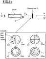
- Fig.1 a shows such a fast optical mode switch, based on an arranged in the illumination beam path electro-optic modulator EOM and passive phase elements P.
- the passive phase elements shown by way of example each consist here of a combination of a birefringent crystal, illustrated is a phase plate P in the form of a split ⁇ / 2 plate, and a component which is polarization-direction independent with respect to the phase, for example formed as glass.
- the phase plate is aligned so that the fast direction of the crystal is advantageously aligned parallel or perpendicular or at a further optimized angle to the incident laser polarization.
- phase plate P various modifications of the phase plate P are shown, a half-sided division into a half half and a half glass in P1, a quarter division in opposite half quarter and glass quarter in P2, an outboard ⁇ / 2 ring and an inner glass core in P3 and vice versa an outer glass ring and an inner A / 2 core in P4.
- Glass is only listed here by way of example.
- Amorphous quartz [Suprasil] or other non-birefringent materials can also be used.
- the orientation of the extraordinary axis of the respective ⁇ / 2 part is shown in each case as an arrow. If a light beam polarized parallel to this direction of the arrow passes through this element, a phase shift of half a wavelength relative to the glass part is produced in the ⁇ / 2 part.
- the element P is in operative connection with the EOM, which causes by appropriate control a rapid rotation of the polarization direction PR of the incident light beam L, usually a linearly polarized laser beam.
- the light beam After passing through P, the light beam, as in the arrangements shown below, continues in the direction of the microscope M via a scanning unit, not shown, to the sample, as is also known from the prior art.
- the invention also relates to a control method, wherein advantageously the formation of the phase element, for example by replacement or control of a SLM is changed and a measurement of the modulation contrast, for example via measurements with activated disk P and swung plate P (without FMM) an optimization of the FMM Signal can occur.
- a rotation of the plate P can be carried out with a fixed light beam L instead of the rotation of the polarization by the EOM.
- Fig. 1c shows as in Fig. 1a the fast optical mode switch based on an EOM and passive phase elements.
- the inventive approach is extended to the point that now the modulation of the polarization direction of the laser before coupling into a fiber F can take place, if this fiber, as known in polarization-maintaining fibers, receives the polarization state of the light.
- the phase element is then after the fiber again in a pupil of the optical system.
- This embodiment is particularly advantageous if there is little space available in the actual optical system / device / microscope / scan head.
- a solution is realized according to the invention, in which the two modes are already present and switched between these modes by means of an EOM, AOM or AOTF.
- This principle differs even further from the previously documented prior art, since now switching in focus does not take place via a switching of the optical phases, but between two optical field modes.
- an equivalent initial and final state is established, but the transition from one configuration to the other another configuration characterized by the respective focus field structure is incoherent.
- C (r) denotes the spatially varying concentration of excitable molecules.
- the integral extends over an area containing the focal volume.
- I p ( r , t ) denotes the temporally varying excitation intensity, which in the case of switching between two modes by I P r ⁇ G r 1 + cos .omega.t + LG r 1 + Sin .omega.t given is.
- the time-varying proportion can then be separated from the time-constant proportion. This time-varying proportion corresponds to the difference between the two different focus fields, wherein the non-modulated off-focus portion is constant in time and is eliminated by the in-phase detection via, for example, a lock-in detection.
- Figure 2b shows the intensity distribution of a Gaussian mode and a Donut mode (Laguerre-Gauss mode).
- the axes indicate a scaled lateral spatial extent in the focal plane.
- the proposed solution differs from the prior art in particular the fact that here the light field is not broken down into its components in the pupil and is influenced by a phase modulator in different spatial parts, but that there is a temporally varying switching between two different focus fields.
- Another advantage of the solution is its easy expandability to multiple focal volumes. In this case, for example, one would irradiate several Gaussian beams into the arrangement and transform these on the corresponding optical path by means of an array transformer (eg a spiral phase mask array).
- an array transformer eg a spiral phase mask array
- Shown here is a multispot variant for mode modulation with the example of 4 preferably collimated beams L1-4, which are finally focused in the microscope M in the direction of the focal plane.
- L1-4 The passage of L1-4 is analog 2a by the arrangement shown there, wherein instead of a single spiral phase mask here an SPP array, shown schematically by four SPP, is provided.
- the latter can have a correspondingly large cross section or can also be arranged upstream of the multi-spot generation in the light direction or it can be several EOMs for L1-4, even with different modulation frequencies, or a segmented EOM with differently controlled cross-sectional areas , be provided.
- Fig. 2c only four beams are shown, and the invention can ultimately be advantageously designed to modulate a significantly larger number of beams and thus to enable a quasi-confocal multi-focus microscopy.
- a detector array in the descanned case or a camera with a modulatable amplifier (multichannel plate) [4] or even smart pixel CMOS cameras [3] which permit pixel-wise demodulation in the camera, in the nondescanned or direct detection mode.
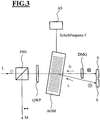
- FIG. 3 shows the fast switching between two field modes (eg Laguerre-Gauss and Gaussian mode) by means of an AOM, ie transformation of a Gaussian field into a time-dependent superposition of a Gaussian and Gaussian Laguerre mode.
- AOM acousto-optic modulator
- a "donut mode generator” DMG (eg spiral phase plate or “radial polarizer”) is provided in the beam path between AOM and S,
- This embodiment of the invention represents an advantageous variation of the above-mentioned embodiment 2a.
- a Gaussian beam with a linear polarization by a polarizing beam splitter and a polarization influencing Quarter-wave plate into an AOM or AOTF controlled by a drive unit AS (for very fast switching an AOM, in the case of slower but polychromatic modulation an AOTF can also be used).
- a time varying lattice can be formed in the AOM, at which this beam is deflected, for example, into its 0th and 1st order. Between these orders is thus switched quickly (high frequency) back and forth.
- the steel passes then again in one of the ways a mode-generating element such as a donut mode generating element DMG, where in addition to donut modes, other mode-generating elements, eg for generating higher Gauss-Laguerre modes, are conceivable, and is subsequently at a first Mirror reflected. Thereafter, the element will pass a second time.
- the other order is reflected only on a mirror.
- Both orders then again pass through the AOM and are again brought into a beam direction in the AOM, whereby they usually leave the AOM again in the linear output polarization depending on the mode-generating element.
- the beam is then brought to the reflection at the polarizing beam splitter cube PBS and can thus move in the direction of the microscope M and the sample.
- the detection of the emitted fluorescence radiation takes place with corresponding optoelectronic detectors and an optical or electronic demodulation.
- Lock-in techniques are based on the phase dependent measurement of time modulated signals, the basis being a frequency reference. Typically, the sample is excited at a particular frequency, while the LI measures the signal at the reference frequency.
- the lock-in system LI detects the signal at this specific reference frequency as a function of the reference phase position.
- the signal is first amplified and then multiplied by the LI reference LI ref using a phase-sensitive detector (PSD) or a multiplier.
- PSD phase-sensitive detector
- the output of the PSD provides two time-varying signals: one at the differential and one at the sum frequency of the LI reference phase and signal phase.
- TP 1 / 2 V S V L cos ⁇ S - ⁇ ref ,
- optical modulators are used for demodulation in the detection or the operation of the detectors used for demodulation.
- Figure 4a shows a microscope structure to increase the penetration depth / scattered light suppression being provided in a schematic beam path of a laser L in the direction of a sample P, a dichroic splitter mirror D for the separation of illumination and detection beam path.
- the laser L for fluorescence excitation is using a focus modulator (FM) such as Fig. 1 and 2 described modulated with the frequency ⁇ .
- FM focus modulator
- BS beam splitter
- one modulator m is used in each case before d1 and d2 (m1, m2 in FIG. 3a) or the detector gain of d1 and d2 is modulated (3b).
- filter F e.g., integrator
- the modulators M1, m2 may advantageously be optical modulators such as EOM.
- m1 is directly modulated and m2 undergoes a phase shift over Ph, thereby two partial signals are detected, which have a phase difference to each other (delta Phi) and mixed and filtered with low-pass filter, so there is advantageously an optical demodulation with set relative phase, ideally of 90 degrees between the two detection components in order to be able to subtract the states with intact focus and the shifted states in which the focus is disturbed by the destructive interference (- operator), Thus, on each pixel, the signal from the focus subtracts the extra-focal background (stray light).
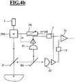
- Fig. 4b is not the optical signal modulated but the "gain" of the detectors (eg acceleration voltage of a PMT), each controlled via FM and again via Ph the phase adjusted, the signals filtered with F and subtracted with O.
- the "gain" of the detectors eg acceleration voltage of a PMT
- the detectors d1, d2 are switched on and off, for example, with frequency ⁇ (and set phase shift).
- a beam switchover is used for demodulation by means of AOM.
- Figure 4c shows a ray path similar to Fig. 3 shown.
- Ph can be used to set the phase difference.
- Fig. 6-8 are further advantageous embodiments shown in addition.
- the first supplement concerns the structure of the phase plate itself. This was originally described as consisting of a combination of a lambda / 2 plate and an isotropically acting plate. However, more general combinations are also conceivable.
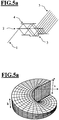
- the plate PP as in Fig. 6 be composed of areas that have the effect of a lambda plate (and thus the phase corresponding to lambda and not lambda / 2 push) and areas in which a lambda / 2-phase shift is achieved.
- any phase shift in different subregions of the phase plate can be realized by setting the difference to the advantageous value of lambda / 2.
- Fig. 1 illustrated different embodiments of a combination of different areas can be as in Fig. 6 shown, even for different areas, for example, have a phase delay of lambda or lambda / half as shown. It is also particularly advantageous to achromatize the phase deviation of the two subregions against each other.
- achromatic wave plates or “achromatic retardation plates” which consist for example of different birefringent crystals and have the same optical properties (the same phase delay) for a broadband wavelength range and then the phase characteristic of the isotropic subplate is adapted thereon by, for example Plates consisting of at least two glasses can be used.
- the polarization after the PBS has a predetermined value.
- a rotatable or otherwise adjustable with respect to its polarization influencing polarizer can be introduced.
- an intensity balance between the two partial beams can be made after the optical fibers.
- the relevant measurement can be performed in a microscope or with an external monitor diode.
- a part of the beam can be coupled to a diode D after the PBS.
- the intensity fluctuations, which are measured with the diode, are used inter alia as a control variable to set the maximum amplitudes of the frequencies f ac 1 and f ac 2 .
- the method can be used for the switching of N light states with, for example, N fibers.
- Fig. 7 describes the fast switching of the polarization by means of an AOD in combination with a fiber optic F1, F2 for generating the phase switching by means of a suitable phase plate PP. Embodiments for balancing the intensities of both switching states are shown.
- the light of the laser light wave L is irradiated via a lens L1 in the plane of an AOD (acousto-optical deflector) whose sound wave is switched in the crystal with a frequency F between different acoustic frequencies F1 and F2, which generate alternately different deflection angle of the laser beam.
- the alternately deflected laser beams La1, La2 are in each case introduced via fiber coupler FKein in optical fiber F1, F2 and coupled out by means of Faserauskopplern FKaus from at different positions on a pole piece PBS.
- the fibers F1 and F2 are in this case set up so that their (preferably linear) polarization is perpendicular to the PBS laterally and perpendicular to each other from above. This is effected by corresponding rotation of the fiber ends or the decoupling units, it being possible for the optimum position on the PBS to be set behind the PBS for F1 and F2 on the basis of the signal yield.
- the phase plate PP is as in Fig. 6 arranged and generated by the phase jump between their halves the FMM signal for transmission into the microscope and the scanning device.
- a monitor diode D can be coupled, which serves via a drive unit AS for setting the signal intensities and the ratio of the two pole components.
- a rotatable polarizer is advantageously provided between PP and ST, which can serve to fine tune the ratio of the two pole components and to compensate for possible errors in the orientation of the fibers F1, F2 to each other as mentioned above.
- the detection via the monitor diode can be synchronized to the frequency of the switching by the AOD, so that the individual intensity components can be separated from one another.
- Fig. 8 describes a further embodiment with an EOM for switching the polarization and thus the phase after the phase plate in conjunction with the components, as described above Fig. 7 represented, in analogous mode of action as in Fig7 ,
- the separation into the individual polarization components takes place by means of a pole splitter PBS1 behind the EOM, wherein after the PBS the different pole components are in turn coupled into separate fibers F1, F2, which in turn on PBS 2 by orientation of the fibers or the outcouplings FK with each other perpendicular polarizations are irradiated.
Landscapes
- Physics & Mathematics (AREA)
- General Physics & Mathematics (AREA)
- Optics & Photonics (AREA)
- Nonlinear Science (AREA)
- Chemical & Material Sciences (AREA)
- Analytical Chemistry (AREA)
- Microscoopes, Condenser (AREA)
Priority Applications (1)
| Application Number | Priority Date | Filing Date | Title |
|---|---|---|---|
| EP17202895.3A EP3422088A1 (de) | 2010-10-01 | 2011-09-29 | Mikroskop und mikroskopierverfahren |
Applications Claiming Priority (2)
| Application Number | Priority Date | Filing Date | Title |
|---|---|---|---|
| DE102010047352 | 2010-10-01 | ||
| DE102011013613A DE102011013613A1 (de) | 2010-10-01 | 2011-03-08 | Mikroskop und Mikroskopierverfahren |
Related Child Applications (1)
| Application Number | Title | Priority Date | Filing Date |
|---|---|---|---|
| EP17202895.3A Division EP3422088A1 (de) | 2010-10-01 | 2011-09-29 | Mikroskop und mikroskopierverfahren |
Publications (3)
| Publication Number | Publication Date |
|---|---|
| EP2437096A2 EP2437096A2 (de) | 2012-04-04 |
| EP2437096A3 EP2437096A3 (de) | 2012-05-09 |
| EP2437096B1 true EP2437096B1 (de) | 2017-11-22 |
Family
ID=44992443
Family Applications (2)
| Application Number | Title | Priority Date | Filing Date |
|---|---|---|---|
| EP11007920.9A Active EP2437096B1 (de) | 2010-10-01 | 2011-09-29 | Mikroskop und Mikroskopierverfahren |
| EP17202895.3A Withdrawn EP3422088A1 (de) | 2010-10-01 | 2011-09-29 | Mikroskop und mikroskopierverfahren |
Family Applications After (1)
| Application Number | Title | Priority Date | Filing Date |
|---|---|---|---|
| EP17202895.3A Withdrawn EP3422088A1 (de) | 2010-10-01 | 2011-09-29 | Mikroskop und mikroskopierverfahren |
Country Status (4)
| Country | Link |
|---|---|
| US (2) | US10156710B2 (enExample) |
| EP (2) | EP2437096B1 (enExample) |
| JP (2) | JP5911683B2 (enExample) |
| DE (1) | DE102011013613A1 (enExample) |
Families Citing this family (32)
| Publication number | Priority date | Publication date | Assignee | Title |
|---|---|---|---|---|
| DE102010013830A1 (de) * | 2010-03-26 | 2011-09-29 | Carl Zeiss Microlmaging Gmbh | Mikroskop und Verfahren zur mikroskopischen Erfassung von Licht einer Probe |
| DE102012010207B4 (de) | 2012-05-15 | 2024-02-29 | Carl Zeiss Microscopy Gmbh | Mikroskop und Mikroskopieverfahren |
| EP2888620A1 (en) | 2012-08-24 | 2015-07-01 | Advanced Micro Devices, Inc. | Laser scanning module including an optical isolator |
| DE102012017922B4 (de) * | 2012-09-11 | 2024-03-14 | Carl Zeiss Microscopy Gmbh | Optikanordnung und Lichtmikroskop |
| DE102012019464A1 (de) * | 2012-09-28 | 2014-04-03 | Carl Zeiss Microscopy Gmbh | Konfokales Auflicht-Rastermikroskop zur Multifleck-Abtastung |
| CN103197411B (zh) * | 2013-03-20 | 2017-05-10 | 中国科学院苏州生物医学工程技术研究所 | 一种位相板组件及可变景深的显微镜系统 |
| DE102013227103B4 (de) * | 2013-09-03 | 2018-05-30 | Leica Microsystems Cms Gmbh | Mikroskop mit einer akustooptischen Vorrichtung |
| DE102013218231A1 (de) * | 2013-09-11 | 2015-03-12 | Sirona Dental Systems Gmbh | Optisches System zur Erzeugung eines sich zeitlich ändernden Musters für ein Konfokalmikroskop |
| JP6365662B2 (ja) * | 2014-04-01 | 2018-08-01 | 株式会社ニコン | 超解像観察装置及び超解像観察方法 |
| JP6511041B2 (ja) | 2014-04-24 | 2019-05-08 | オリンパス株式会社 | 顕微鏡および顕微鏡観察方法 |
| JP2015210517A (ja) * | 2014-09-09 | 2015-11-24 | 株式会社ニコン | パターン描画装置、パターン描画方法、および、デバイス製造方法 |
| WO2016208322A1 (ja) * | 2015-06-23 | 2016-12-29 | オリンパス株式会社 | 画像取得装置および画像取得方法 |
| US10067072B2 (en) * | 2015-07-10 | 2018-09-04 | Kla-Tencor Corporation | Methods and apparatus for speckle suppression in laser dark-field systems |
| WO2017046863A1 (ja) | 2015-09-15 | 2017-03-23 | オリンパス株式会社 | 顕微鏡および顕微鏡観察方法 |
| DE102016211374A1 (de) | 2016-06-24 | 2017-12-28 | Carl Zeiss Microscopy Gmbh | Mikroskopieverfahren unter Nutzung zeitlicher Fokusmodulation und Mikroskop |
| US10540571B2 (en) | 2016-12-22 | 2020-01-21 | Advanced Optical Technologies, Inc. | Polarimeter with multiple independent tunable channels and method for material and object classification and recognition |
| US11867891B2 (en) | 2016-12-22 | 2024-01-09 | Advanced Optical Technologies, Inc. | Polarimeter with multiple independent tunable channels and method for material orientation imaging |
| JP7287961B2 (ja) * | 2017-12-12 | 2023-06-06 | アレン インスティテュート | 同時複数平面撮像のためのシステム、装置および方法 |
| DE102018110083A1 (de) * | 2018-04-26 | 2019-10-31 | Carl Zeiss Microscopy Gmbh | Optikanordnung zur flexiblen Mehrfarbbeleuchtung für ein Lichtmikroskop und Verfahren hierzu |
| KR102617346B1 (ko) * | 2018-06-28 | 2023-12-26 | 삼성전자주식회사 | 산란 억제를 위한 절단용 레이저 장치 |
| US11075496B2 (en) | 2018-06-28 | 2021-07-27 | Samsung Electronics Co., Ltd. | Laser dicing device, method of laser beam modulation, and method of dicing a substrate |
| KR102155329B1 (ko) * | 2018-11-09 | 2020-09-11 | 경북대학교 산학협력단 | 라이트 필드 이미징 시스템 |
| US10942135B2 (en) * | 2018-11-14 | 2021-03-09 | Kla Corporation | Radial polarizer for particle detection |
| CN109539976A (zh) * | 2018-11-23 | 2019-03-29 | 哈尔滨工业大学 | 基于螺旋相位板的零差干涉仪非线性误差修正方法与装置 |
| US11395714B2 (en) | 2019-11-11 | 2022-07-26 | Dermlite Llc | Medical illuminator with variable polarization |
| US11346769B2 (en) | 2020-02-20 | 2022-05-31 | Onto Innovation Inc. | Fast generalized multi-wavelength ellipsometer |
| US11346768B1 (en) * | 2020-12-02 | 2022-05-31 | Onto Innovation Inc. | Vortex polarimeter |
| CN112505914B (zh) * | 2020-12-10 | 2022-03-22 | 武汉先河激光技术有限公司 | 一种涡旋光束生成系统、方法及相位调制组合装置 |
| CN112987321B (zh) * | 2021-03-22 | 2022-08-02 | 中国科学院光电技术研究所 | 一种生成高功率涡旋激光的方法和装置 |
| CN113467073B (zh) * | 2021-04-29 | 2022-08-09 | 西安交通大学 | 一种基于柱矢量光场的激光微小频率偏移装置及方法 |
| CN113608359B (zh) * | 2021-08-19 | 2023-08-11 | 中国科学院光电技术研究所 | 一种模式可调的腔内涡旋光束生成装置 |
| JP7446540B2 (ja) * | 2022-02-04 | 2024-03-08 | 三菱電機株式会社 | 動的光パターン生成装置 |
Family Cites Families (21)
| Publication number | Priority date | Publication date | Assignee | Title |
|---|---|---|---|---|
| US3628848A (en) * | 1969-12-23 | 1971-12-21 | Anvar | Variable phase contrast microscopy |
| US5034613A (en) | 1989-11-14 | 1991-07-23 | Cornell Research Foundation, Inc. | Two-photon laser microscopy |
| JPH07167933A (ja) * | 1993-12-15 | 1995-07-04 | Nikon Corp | 磁気偏光顕微鏡 |
| JPH07187933A (ja) * | 1993-12-24 | 1995-07-25 | Sekisui Plastics Co Ltd | 土壌抗菌剤 |
| GB9603788D0 (en) * | 1996-02-22 | 1996-04-24 | Isis Innovation | Confocal microscope |
| US6134010A (en) * | 1997-11-07 | 2000-10-17 | Lucid, Inc. | Imaging system using polarization effects to enhance image quality |
| US6151127A (en) * | 1998-05-28 | 2000-11-21 | The General Hospital Corporation | Confocal microscopy |
| US20050134841A1 (en) * | 1998-09-18 | 2005-06-23 | Mehdi Vacz-Iravani | Sample inspection system |
| DE19904592C2 (de) | 1999-02-05 | 2001-03-08 | Lavision Gmbh | Strahlteilervorrichtung |
| TW558642B (en) * | 1999-08-02 | 2003-10-21 | Zetetic Inst | Scanning interferometric near-field confocal microscopy |
| US7038848B2 (en) * | 2002-12-27 | 2006-05-02 | Olympus Corporation | Confocal microscope |
| JP2005345561A (ja) * | 2004-05-31 | 2005-12-15 | Olympus Corp | 走査型レーザ顕微鏡装置 |
| DE102004034987A1 (de) * | 2004-07-16 | 2006-02-02 | Carl Zeiss Jena Gmbh | Lichtrastermikroskop und Verwendung |
| JP2006058477A (ja) * | 2004-08-18 | 2006-03-02 | Olympus Corp | 超解像顕微鏡 |
| JP5189301B2 (ja) | 2007-03-12 | 2013-04-24 | オリンパス株式会社 | レーザー走査型顕微鏡 |
| JP5551069B2 (ja) | 2007-07-06 | 2014-07-16 | ナショナル ユニヴァーシティー オブ シンガポール | 蛍光焦点変調顕微鏡システムおよびその方法 |
| WO2009012789A1 (en) * | 2007-07-20 | 2009-01-29 | Medizinische Universität Innsbruck | Optical device with a pair of diffractive optical elements |
| JP5484879B2 (ja) * | 2009-12-11 | 2014-05-07 | オリンパス株式会社 | 超解像顕微鏡 |
| SMT202000624T1 (it) * | 2010-03-05 | 2021-01-05 | Massachusetts Gen Hospital | Apparecchio per fornire radiazione elettromagnetica a un campione |
| JP5752360B2 (ja) * | 2010-03-12 | 2015-07-22 | 富士フイルム株式会社 | ポリエステルフィルムの溶融製膜方法及び太陽電池部材用ポリエステルフィルム |
| DE102010013829A1 (de) * | 2010-03-26 | 2011-09-29 | Carl Zeiss Microlmaging Gmbh | Mikroskop und Verfahren zur Erfassung von Probenlicht |
-
2011
- 2011-03-08 DE DE102011013613A patent/DE102011013613A1/de not_active Withdrawn
- 2011-08-31 JP JP2011189560A patent/JP5911683B2/ja active Active
- 2011-09-29 EP EP11007920.9A patent/EP2437096B1/de active Active
- 2011-09-29 EP EP17202895.3A patent/EP3422088A1/de not_active Withdrawn
- 2011-10-03 US US13/251,452 patent/US10156710B2/en active Active
-
2016
- 2016-03-30 JP JP2016067831A patent/JP6453266B2/ja active Active
- 2016-10-20 US US15/298,424 patent/US20170068082A1/en not_active Abandoned
Non-Patent Citations (1)
| Title |
|---|
| None * |
Also Published As
| Publication number | Publication date |
|---|---|
| JP6453266B2 (ja) | 2019-01-16 |
| JP2016118811A (ja) | 2016-06-30 |
| JP5911683B2 (ja) | 2016-04-27 |
| US10156710B2 (en) | 2018-12-18 |
| DE102011013613A1 (de) | 2012-04-05 |
| EP3422088A1 (de) | 2019-01-02 |
| EP2437096A3 (de) | 2012-05-09 |
| EP2437096A2 (de) | 2012-04-04 |
| JP2012078802A (ja) | 2012-04-19 |
| US20120268812A1 (en) | 2012-10-25 |
| US20170068082A1 (en) | 2017-03-09 |
Similar Documents
| Publication | Publication Date | Title |
|---|---|---|
| EP2437096A2 (de) | Mikroskop und Mikroskopierverfahren | |
| EP2149070B1 (de) | Durchstimmbares akusto-optisches filterelement | |
| EP3042239B1 (de) | Rastermikroskop mit polarisierter probenbeleuchtung | |
| DE10042840A1 (de) | Vorrichtung und Verfahren zur Anregung von Fluoreszenzmikroskopmarkern bei der Mehrphotonen-Rastermikroskopie | |
| DE102010013830A1 (de) | Mikroskop und Verfahren zur mikroskopischen Erfassung von Licht einer Probe | |
| DE102012010207B4 (de) | Mikroskop und Mikroskopieverfahren | |
| DE2240968A1 (de) | Optisches verfahren zur messung der relativen verschiebung eines beugungsgitters sowie einrichtungen zu seiner durchfuehrung | |
| DE3013498A1 (de) | Optischer modulator sowie laser-graviervorrichtung mit einem derartigen modulator | |
| EP2788810A1 (de) | Hochauflösendes lichtmikroskop | |
| EP3042233B1 (de) | Mikroskop mit einer akustooptischen vorrichtung | |
| EP3042232A1 (de) | Scanmikroskop und akustooptischer hauptstrahlteiler für ein scanmikroskop | |
| EP2553512A2 (de) | Mikroskop und verfahren zur erfassung von probenlicht | |
| DE102010026205A1 (de) | Mikroskop, insbesondere Fluoreszenzmikroskop, dichroitischer Strahlteiler und dessen Verwendung | |
| DE68925254T2 (de) | Generator für die zweite Harmonische und denselben benutzendes Informationssystem | |
| EP3359997A1 (de) | Verfahren und vorrichtung zum untersuchen einer probe mit einer strukturiereten lichtblattbeleuchtung | |
| EP1720052A1 (de) | Vorrichtung zur Steuerung von Lichtstrahlung | |
| DE102018110072A1 (de) | Optikanordnung zur strukturierten Beleuchtung für ein Lichtmikroskop und Verfahren hierzu | |
| WO2017220668A1 (de) | Mikroskopieverfahren unter nutzung zeitlicher fokusmodulation und mikroskop | |
| DE112022005163T5 (de) | Lichtbestrahlungsvorrichtung, Mikroskop, Lichtbestrahlungsverfahren und Bildaufnahmeverfahren | |
| WO2015032819A1 (de) | Mikroskop mit einem element zum verändern der form des beleuchtungslichtfokus | |
| WO2012096629A1 (en) | Spatial-temporal optical phase modulation method and apparatus | |
| DE112022005149T5 (de) | Mikroskop und Bildverarbeitungsverfahren |
Legal Events
| Date | Code | Title | Description |
|---|---|---|---|
| PUAI | Public reference made under article 153(3) epc to a published international application that has entered the european phase |
Free format text: ORIGINAL CODE: 0009012 |
|
| 17P | Request for examination filed |
Effective date: 20110929 |
|
| AK | Designated contracting states |
Kind code of ref document: A2 Designated state(s): AL AT BE BG CH CY CZ DE DK EE ES FI FR GB GR HR HU IE IS IT LI LT LU LV MC MK MT NL NO PL PT RO RS SE SI SK SM TR |
|
| AX | Request for extension of the european patent |
Extension state: BA ME |
|
| PUAL | Search report despatched |
Free format text: ORIGINAL CODE: 0009013 |
|
| AK | Designated contracting states |
Kind code of ref document: A3 Designated state(s): AL AT BE BG CH CY CZ DE DK EE ES FI FR GB GR HR HU IE IS IT LI LT LU LV MC MK MT NL NO PL PT RO RS SE SI SK SM TR |
|
| AX | Request for extension of the european patent |
Extension state: BA ME |
|
| RIC1 | Information provided on ipc code assigned before grant |
Ipc: G02B 21/00 20060101AFI20120405BHEP |
|
| RAP1 | Party data changed (applicant data changed or rights of an application transferred) |
Owner name: CARL ZEISS MICROSCOPY GMBH |
|
| 17Q | First examination report despatched |
Effective date: 20160105 |
|
| GRAP | Despatch of communication of intention to grant a patent |
Free format text: ORIGINAL CODE: EPIDOSNIGR1 |
|
| RIC1 | Information provided on ipc code assigned before grant |
Ipc: G02B 21/00 20060101AFI20170120BHEP Ipc: G02B 26/06 20060101ALI20170120BHEP |
|
| INTG | Intention to grant announced |
Effective date: 20170213 |
|
| GRAS | Grant fee paid |
Free format text: ORIGINAL CODE: EPIDOSNIGR3 |
|
| GRAA | (expected) grant |
Free format text: ORIGINAL CODE: 0009210 |
|
| AK | Designated contracting states |
Kind code of ref document: B1 Designated state(s): AL AT BE BG CH CY CZ DE DK EE ES FI FR GB GR HR HU IE IS IT LI LT LU LV MC MK MT NL NO PL PT RO RS SE SI SK SM TR |
|
| REG | Reference to a national code |
Ref country code: GB Ref legal event code: FG4D Free format text: NOT ENGLISH |
|
| RIN1 | Information on inventor provided before grant (corrected) |
Inventor name: ANHUT, TIEMO Inventor name: KALKBRENNER, THOMAS Inventor name: SCHWEDT, DANIEL |
|
| REG | Reference to a national code |
Ref country code: CH Ref legal event code: EP |
|
| REG | Reference to a national code |
Ref country code: IE Ref legal event code: FG4D Free format text: LANGUAGE OF EP DOCUMENT: GERMAN |
|
| REG | Reference to a national code |
Ref country code: AT Ref legal event code: REF Ref document number: 948915 Country of ref document: AT Kind code of ref document: T Effective date: 20171215 |
|
| REG | Reference to a national code |
Ref country code: DE Ref legal event code: R096 Ref document number: 502011013320 Country of ref document: DE |
|
| REG | Reference to a national code |
Ref country code: NL Ref legal event code: MP Effective date: 20171122 |
|
| REG | Reference to a national code |
Ref country code: LT Ref legal event code: MG4D |
|
| PG25 | Lapsed in a contracting state [announced via postgrant information from national office to epo] |
Ref country code: SE Free format text: LAPSE BECAUSE OF FAILURE TO SUBMIT A TRANSLATION OF THE DESCRIPTION OR TO PAY THE FEE WITHIN THE PRESCRIBED TIME-LIMIT Effective date: 20171122 Ref country code: ES Free format text: LAPSE BECAUSE OF FAILURE TO SUBMIT A TRANSLATION OF THE DESCRIPTION OR TO PAY THE FEE WITHIN THE PRESCRIBED TIME-LIMIT Effective date: 20171122 Ref country code: FI Free format text: LAPSE BECAUSE OF FAILURE TO SUBMIT A TRANSLATION OF THE DESCRIPTION OR TO PAY THE FEE WITHIN THE PRESCRIBED TIME-LIMIT Effective date: 20171122 Ref country code: NO Free format text: LAPSE BECAUSE OF FAILURE TO SUBMIT A TRANSLATION OF THE DESCRIPTION OR TO PAY THE FEE WITHIN THE PRESCRIBED TIME-LIMIT Effective date: 20180222 Ref country code: LT Free format text: LAPSE BECAUSE OF FAILURE TO SUBMIT A TRANSLATION OF THE DESCRIPTION OR TO PAY THE FEE WITHIN THE PRESCRIBED TIME-LIMIT Effective date: 20171122 Ref country code: NL Free format text: LAPSE BECAUSE OF FAILURE TO SUBMIT A TRANSLATION OF THE DESCRIPTION OR TO PAY THE FEE WITHIN THE PRESCRIBED TIME-LIMIT Effective date: 20171122 |
|
| PG25 | Lapsed in a contracting state [announced via postgrant information from national office to epo] |
Ref country code: HR Free format text: LAPSE BECAUSE OF FAILURE TO SUBMIT A TRANSLATION OF THE DESCRIPTION OR TO PAY THE FEE WITHIN THE PRESCRIBED TIME-LIMIT Effective date: 20171122 Ref country code: RS Free format text: LAPSE BECAUSE OF FAILURE TO SUBMIT A TRANSLATION OF THE DESCRIPTION OR TO PAY THE FEE WITHIN THE PRESCRIBED TIME-LIMIT Effective date: 20171122 Ref country code: BG Free format text: LAPSE BECAUSE OF FAILURE TO SUBMIT A TRANSLATION OF THE DESCRIPTION OR TO PAY THE FEE WITHIN THE PRESCRIBED TIME-LIMIT Effective date: 20180222 Ref country code: LV Free format text: LAPSE BECAUSE OF FAILURE TO SUBMIT A TRANSLATION OF THE DESCRIPTION OR TO PAY THE FEE WITHIN THE PRESCRIBED TIME-LIMIT Effective date: 20171122 Ref country code: GR Free format text: LAPSE BECAUSE OF FAILURE TO SUBMIT A TRANSLATION OF THE DESCRIPTION OR TO PAY THE FEE WITHIN THE PRESCRIBED TIME-LIMIT Effective date: 20180223 |
|
| PG25 | Lapsed in a contracting state [announced via postgrant information from national office to epo] |
Ref country code: CZ Free format text: LAPSE BECAUSE OF FAILURE TO SUBMIT A TRANSLATION OF THE DESCRIPTION OR TO PAY THE FEE WITHIN THE PRESCRIBED TIME-LIMIT Effective date: 20171122 Ref country code: CY Free format text: LAPSE BECAUSE OF FAILURE TO SUBMIT A TRANSLATION OF THE DESCRIPTION OR TO PAY THE FEE WITHIN THE PRESCRIBED TIME-LIMIT Effective date: 20171122 Ref country code: EE Free format text: LAPSE BECAUSE OF FAILURE TO SUBMIT A TRANSLATION OF THE DESCRIPTION OR TO PAY THE FEE WITHIN THE PRESCRIBED TIME-LIMIT Effective date: 20171122 Ref country code: DK Free format text: LAPSE BECAUSE OF FAILURE TO SUBMIT A TRANSLATION OF THE DESCRIPTION OR TO PAY THE FEE WITHIN THE PRESCRIBED TIME-LIMIT Effective date: 20171122 Ref country code: SK Free format text: LAPSE BECAUSE OF FAILURE TO SUBMIT A TRANSLATION OF THE DESCRIPTION OR TO PAY THE FEE WITHIN THE PRESCRIBED TIME-LIMIT Effective date: 20171122 |
|
| REG | Reference to a national code |
Ref country code: DE Ref legal event code: R097 Ref document number: 502011013320 Country of ref document: DE |
|
| PG25 | Lapsed in a contracting state [announced via postgrant information from national office to epo] |
Ref country code: IT Free format text: LAPSE BECAUSE OF FAILURE TO SUBMIT A TRANSLATION OF THE DESCRIPTION OR TO PAY THE FEE WITHIN THE PRESCRIBED TIME-LIMIT Effective date: 20171122 Ref country code: RO Free format text: LAPSE BECAUSE OF FAILURE TO SUBMIT A TRANSLATION OF THE DESCRIPTION OR TO PAY THE FEE WITHIN THE PRESCRIBED TIME-LIMIT Effective date: 20171122 Ref country code: SM Free format text: LAPSE BECAUSE OF FAILURE TO SUBMIT A TRANSLATION OF THE DESCRIPTION OR TO PAY THE FEE WITHIN THE PRESCRIBED TIME-LIMIT Effective date: 20171122 Ref country code: PL Free format text: LAPSE BECAUSE OF FAILURE TO SUBMIT A TRANSLATION OF THE DESCRIPTION OR TO PAY THE FEE WITHIN THE PRESCRIBED TIME-LIMIT Effective date: 20171122 |
|
| REG | Reference to a national code |
Ref country code: FR Ref legal event code: PLFP Year of fee payment: 8 |
|
| PG25 | Lapsed in a contracting state [announced via postgrant information from national office to epo] |
Ref country code: MT Free format text: LAPSE BECAUSE OF FAILURE TO SUBMIT A TRANSLATION OF THE DESCRIPTION OR TO PAY THE FEE WITHIN THE PRESCRIBED TIME-LIMIT Effective date: 20171122 |
|
| PLBE | No opposition filed within time limit |
Free format text: ORIGINAL CODE: 0009261 |
|
| STAA | Information on the status of an ep patent application or granted ep patent |
Free format text: STATUS: NO OPPOSITION FILED WITHIN TIME LIMIT |
|
| 26N | No opposition filed |
Effective date: 20180823 |
|
| PG25 | Lapsed in a contracting state [announced via postgrant information from national office to epo] |
Ref country code: SI Free format text: LAPSE BECAUSE OF FAILURE TO SUBMIT A TRANSLATION OF THE DESCRIPTION OR TO PAY THE FEE WITHIN THE PRESCRIBED TIME-LIMIT Effective date: 20171122 |
|
| PG25 | Lapsed in a contracting state [announced via postgrant information from national office to epo] |
Ref country code: MC Free format text: LAPSE BECAUSE OF FAILURE TO SUBMIT A TRANSLATION OF THE DESCRIPTION OR TO PAY THE FEE WITHIN THE PRESCRIBED TIME-LIMIT Effective date: 20171122 |
|
| REG | Reference to a national code |
Ref country code: CH Ref legal event code: PL |
|
| REG | Reference to a national code |
Ref country code: BE Ref legal event code: MM Effective date: 20180930 |
|
| REG | Reference to a national code |
Ref country code: IE Ref legal event code: MM4A |
|
| PG25 | Lapsed in a contracting state [announced via postgrant information from national office to epo] |
Ref country code: LU Free format text: LAPSE BECAUSE OF NON-PAYMENT OF DUE FEES Effective date: 20180929 |
|
| PG25 | Lapsed in a contracting state [announced via postgrant information from national office to epo] |
Ref country code: IE Free format text: LAPSE BECAUSE OF NON-PAYMENT OF DUE FEES Effective date: 20180929 |
|
| PG25 | Lapsed in a contracting state [announced via postgrant information from national office to epo] |
Ref country code: LI Free format text: LAPSE BECAUSE OF NON-PAYMENT OF DUE FEES Effective date: 20180930 Ref country code: BE Free format text: LAPSE BECAUSE OF NON-PAYMENT OF DUE FEES Effective date: 20180930 Ref country code: CH Free format text: LAPSE BECAUSE OF NON-PAYMENT OF DUE FEES Effective date: 20180930 |
|
| REG | Reference to a national code |
Ref country code: AT Ref legal event code: MM01 Ref document number: 948915 Country of ref document: AT Kind code of ref document: T Effective date: 20180929 |
|
| PG25 | Lapsed in a contracting state [announced via postgrant information from national office to epo] |
Ref country code: AT Free format text: LAPSE BECAUSE OF NON-PAYMENT OF DUE FEES Effective date: 20180929 |
|
| PG25 | Lapsed in a contracting state [announced via postgrant information from national office to epo] |
Ref country code: TR Free format text: LAPSE BECAUSE OF FAILURE TO SUBMIT A TRANSLATION OF THE DESCRIPTION OR TO PAY THE FEE WITHIN THE PRESCRIBED TIME-LIMIT Effective date: 20171122 |
|
| PG25 | Lapsed in a contracting state [announced via postgrant information from national office to epo] |
Ref country code: PT Free format text: LAPSE BECAUSE OF FAILURE TO SUBMIT A TRANSLATION OF THE DESCRIPTION OR TO PAY THE FEE WITHIN THE PRESCRIBED TIME-LIMIT Effective date: 20171122 Ref country code: HU Free format text: LAPSE BECAUSE OF FAILURE TO SUBMIT A TRANSLATION OF THE DESCRIPTION OR TO PAY THE FEE WITHIN THE PRESCRIBED TIME-LIMIT; INVALID AB INITIO Effective date: 20110929 |
|
| PG25 | Lapsed in a contracting state [announced via postgrant information from national office to epo] |
Ref country code: MK Free format text: LAPSE BECAUSE OF NON-PAYMENT OF DUE FEES Effective date: 20171122 |
|
| PG25 | Lapsed in a contracting state [announced via postgrant information from national office to epo] |
Ref country code: AL Free format text: LAPSE BECAUSE OF FAILURE TO SUBMIT A TRANSLATION OF THE DESCRIPTION OR TO PAY THE FEE WITHIN THE PRESCRIBED TIME-LIMIT Effective date: 20171122 Ref country code: IS Free format text: LAPSE BECAUSE OF FAILURE TO SUBMIT A TRANSLATION OF THE DESCRIPTION OR TO PAY THE FEE WITHIN THE PRESCRIBED TIME-LIMIT Effective date: 20180322 |
|
| PGFP | Annual fee paid to national office [announced via postgrant information from national office to epo] |
Ref country code: FR Payment date: 20210921 Year of fee payment: 11 |
|
| PGFP | Annual fee paid to national office [announced via postgrant information from national office to epo] |
Ref country code: GB Payment date: 20210920 Year of fee payment: 11 |
|
| GBPC | Gb: european patent ceased through non-payment of renewal fee |
Effective date: 20220929 |
|
| PG25 | Lapsed in a contracting state [announced via postgrant information from national office to epo] |
Ref country code: FR Free format text: LAPSE BECAUSE OF NON-PAYMENT OF DUE FEES Effective date: 20220930 |
|
| PG25 | Lapsed in a contracting state [announced via postgrant information from national office to epo] |
Ref country code: GB Free format text: LAPSE BECAUSE OF NON-PAYMENT OF DUE FEES Effective date: 20220929 |
|
| PGFP | Annual fee paid to national office [announced via postgrant information from national office to epo] |
Ref country code: DE Payment date: 20250919 Year of fee payment: 15 |