EP2436891A2 - Verfahren zur Vorhersage der Aschebelastung eines Partikelfilters und Fahrzeug damit - Google Patents
Verfahren zur Vorhersage der Aschebelastung eines Partikelfilters und Fahrzeug damit Download PDFInfo
- Publication number
- EP2436891A2 EP2436891A2 EP20110183348 EP11183348A EP2436891A2 EP 2436891 A2 EP2436891 A2 EP 2436891A2 EP 20110183348 EP20110183348 EP 20110183348 EP 11183348 A EP11183348 A EP 11183348A EP 2436891 A2 EP2436891 A2 EP 2436891A2
- Authority
- EP
- European Patent Office
- Prior art keywords
- service
- ash
- ash loading
- particulate filter
- maximum
- Prior art date
- Legal status (The legal status is an assumption and is not a legal conclusion. Google has not performed a legal analysis and makes no representation as to the accuracy of the status listed.)
- Granted
Links
- 238000011068 loading method Methods 0.000 title claims abstract description 94
- 238000000034 method Methods 0.000 title claims abstract description 77
- 230000008929 regeneration Effects 0.000 claims abstract description 44
- 238000011069 regeneration method Methods 0.000 claims abstract description 44
- 230000001419 dependent effect Effects 0.000 claims abstract description 10
- 238000009825 accumulation Methods 0.000 claims description 26
- 238000002485 combustion reaction Methods 0.000 claims description 15
- 238000009530 blood pressure measurement Methods 0.000 claims description 3
- 230000001172 regenerating effect Effects 0.000 claims description 2
- 239000000446 fuel Substances 0.000 description 15
- 239000004071 soot Substances 0.000 description 12
- 239000003054 catalyst Substances 0.000 description 7
- 239000003921 oil Substances 0.000 description 6
- 230000008569 process Effects 0.000 description 6
- IJGRMHOSHXDMSA-UHFFFAOYSA-N Atomic nitrogen Chemical compound N#N IJGRMHOSHXDMSA-UHFFFAOYSA-N 0.000 description 4
- 238000012360 testing method Methods 0.000 description 4
- 230000000694 effects Effects 0.000 description 3
- 230000006870 function Effects 0.000 description 3
- 239000007789 gas Substances 0.000 description 3
- 239000003502 gasoline Substances 0.000 description 3
- 238000012423 maintenance Methods 0.000 description 3
- GQPLMRYTRLFLPF-UHFFFAOYSA-N Nitrous Oxide Chemical compound [O-][N+]#N GQPLMRYTRLFLPF-UHFFFAOYSA-N 0.000 description 2
- 239000003225 biodiesel Substances 0.000 description 2
- 238000004140 cleaning Methods 0.000 description 2
- 238000004891 communication Methods 0.000 description 2
- 230000007423 decrease Effects 0.000 description 2
- 239000000314 lubricant Substances 0.000 description 2
- 229910052757 nitrogen Inorganic materials 0.000 description 2
- 239000013618 particulate matter Substances 0.000 description 2
- 238000012935 Averaging Methods 0.000 description 1
- UGFAIRIUMAVXCW-UHFFFAOYSA-N Carbon monoxide Chemical compound [O+]#[C-] UGFAIRIUMAVXCW-UHFFFAOYSA-N 0.000 description 1
- 230000006978 adaptation Effects 0.000 description 1
- 238000013459 approach Methods 0.000 description 1
- 230000033228 biological regulation Effects 0.000 description 1
- 229910002091 carbon monoxide Inorganic materials 0.000 description 1
- 230000015556 catabolic process Effects 0.000 description 1
- 230000008859 change Effects 0.000 description 1
- 230000006835 compression Effects 0.000 description 1
- 238000007906 compression Methods 0.000 description 1
- 238000010276 construction Methods 0.000 description 1
- 238000012937 correction Methods 0.000 description 1
- 238000006731 degradation reaction Methods 0.000 description 1
- 238000005516 engineering process Methods 0.000 description 1
- 238000011049 filling Methods 0.000 description 1
- 238000001914 filtration Methods 0.000 description 1
- 238000010438 heat treatment Methods 0.000 description 1
- 230000010354 integration Effects 0.000 description 1
- 239000010687 lubricating oil Substances 0.000 description 1
- 238000012986 modification Methods 0.000 description 1
- 230000004048 modification Effects 0.000 description 1
- 239000001272 nitrous oxide Substances 0.000 description 1
- 239000003208 petroleum Substances 0.000 description 1
- 230000009467 reduction Effects 0.000 description 1
Images


Classifications
-
- F—MECHANICAL ENGINEERING; LIGHTING; HEATING; WEAPONS; BLASTING
- F01—MACHINES OR ENGINES IN GENERAL; ENGINE PLANTS IN GENERAL; STEAM ENGINES
- F01N—GAS-FLOW SILENCERS OR EXHAUST APPARATUS FOR MACHINES OR ENGINES IN GENERAL; GAS-FLOW SILENCERS OR EXHAUST APPARATUS FOR INTERNAL COMBUSTION ENGINES
- F01N9/00—Electrical control of exhaust gas treating apparatus
- F01N9/002—Electrical control of exhaust gas treating apparatus of filter regeneration, e.g. detection of clogging
-
- F—MECHANICAL ENGINEERING; LIGHTING; HEATING; WEAPONS; BLASTING
- F01—MACHINES OR ENGINES IN GENERAL; ENGINE PLANTS IN GENERAL; STEAM ENGINES
- F01N—GAS-FLOW SILENCERS OR EXHAUST APPARATUS FOR MACHINES OR ENGINES IN GENERAL; GAS-FLOW SILENCERS OR EXHAUST APPARATUS FOR INTERNAL COMBUSTION ENGINES
- F01N3/00—Exhaust or silencing apparatus having means for purifying, rendering innocuous, or otherwise treating exhaust
- F01N3/02—Exhaust or silencing apparatus having means for purifying, rendering innocuous, or otherwise treating exhaust for cooling, or for removing solid constituents of, exhaust
- F01N3/021—Exhaust or silencing apparatus having means for purifying, rendering innocuous, or otherwise treating exhaust for cooling, or for removing solid constituents of, exhaust by means of filters
- F01N3/023—Exhaust or silencing apparatus having means for purifying, rendering innocuous, or otherwise treating exhaust for cooling, or for removing solid constituents of, exhaust by means of filters using means for regenerating the filters, e.g. by burning trapped particles
-
- F—MECHANICAL ENGINEERING; LIGHTING; HEATING; WEAPONS; BLASTING
- F01—MACHINES OR ENGINES IN GENERAL; ENGINE PLANTS IN GENERAL; STEAM ENGINES
- F01N—GAS-FLOW SILENCERS OR EXHAUST APPARATUS FOR MACHINES OR ENGINES IN GENERAL; GAS-FLOW SILENCERS OR EXHAUST APPARATUS FOR INTERNAL COMBUSTION ENGINES
- F01N11/00—Monitoring or diagnostic devices for exhaust-gas treatment apparatus, e.g. for catalytic activity
- F01N11/002—Monitoring or diagnostic devices for exhaust-gas treatment apparatus, e.g. for catalytic activity the diagnostic devices measuring or estimating temperature or pressure in, or downstream of the exhaust apparatus
-
- F—MECHANICAL ENGINEERING; LIGHTING; HEATING; WEAPONS; BLASTING
- F01—MACHINES OR ENGINES IN GENERAL; ENGINE PLANTS IN GENERAL; STEAM ENGINES
- F01N—GAS-FLOW SILENCERS OR EXHAUST APPARATUS FOR MACHINES OR ENGINES IN GENERAL; GAS-FLOW SILENCERS OR EXHAUST APPARATUS FOR INTERNAL COMBUSTION ENGINES
- F01N9/00—Electrical control of exhaust gas treating apparatus
- F01N9/005—Electrical control of exhaust gas treating apparatus using models instead of sensors to determine operating characteristics of exhaust systems, e.g. calculating catalyst temperature instead of measuring it directly
-
- F—MECHANICAL ENGINEERING; LIGHTING; HEATING; WEAPONS; BLASTING
- F01—MACHINES OR ENGINES IN GENERAL; ENGINE PLANTS IN GENERAL; STEAM ENGINES
- F01N—GAS-FLOW SILENCERS OR EXHAUST APPARATUS FOR MACHINES OR ENGINES IN GENERAL; GAS-FLOW SILENCERS OR EXHAUST APPARATUS FOR INTERNAL COMBUSTION ENGINES
- F01N2550/00—Monitoring or diagnosing the deterioration of exhaust systems
- F01N2550/04—Filtering activity of particulate filters
-
- F—MECHANICAL ENGINEERING; LIGHTING; HEATING; WEAPONS; BLASTING
- F01—MACHINES OR ENGINES IN GENERAL; ENGINE PLANTS IN GENERAL; STEAM ENGINES
- F01N—GAS-FLOW SILENCERS OR EXHAUST APPARATUS FOR MACHINES OR ENGINES IN GENERAL; GAS-FLOW SILENCERS OR EXHAUST APPARATUS FOR INTERNAL COMBUSTION ENGINES
- F01N2900/00—Details of electrical control or of the monitoring of the exhaust gas treating apparatus
- F01N2900/06—Parameters used for exhaust control or diagnosing
- F01N2900/16—Parameters used for exhaust control or diagnosing said parameters being related to the exhaust apparatus, e.g. particulate filter or catalyst
- F01N2900/1606—Particle filter loading or soot amount
-
- Y—GENERAL TAGGING OF NEW TECHNOLOGICAL DEVELOPMENTS; GENERAL TAGGING OF CROSS-SECTIONAL TECHNOLOGIES SPANNING OVER SEVERAL SECTIONS OF THE IPC; TECHNICAL SUBJECTS COVERED BY FORMER USPC CROSS-REFERENCE ART COLLECTIONS [XRACs] AND DIGESTS
- Y02—TECHNOLOGIES OR APPLICATIONS FOR MITIGATION OR ADAPTATION AGAINST CLIMATE CHANGE
- Y02T—CLIMATE CHANGE MITIGATION TECHNOLOGIES RELATED TO TRANSPORTATION
- Y02T10/00—Road transport of goods or passengers
- Y02T10/10—Internal combustion engine [ICE] based vehicles
- Y02T10/40—Engine management systems
Definitions
- the present invention relates to the field of internal combustion engines, and, more particularly, to internal combustion engines having exhaust aftertreatment devices.
- Internal combustion engines come in a number of forms, the most common of which are spark-ignited gasoline fueled engines and compression-ignition, diesel-fueled engines.
- the compression-ignition, or diesel-type engine is used in many commercial and industrial power applications because its durability and fuel economy are superior to the spark-ignited gasoline-fueled engines.
- a diesel engine utilizes the heat of the compression of the intake air, into which a timed and metered quantity of fuel is injected, to produce combustion.
- the nature of the diesel engine cycle is that it has a variable air-fuel ratio that can, under partial power conditions, rise to levels significantly above stoichiometric. This results in enhanced fuel economy since only the quantity of fuel needed for a particular power level is supplied to the engine.
- a particulate filter (PF) in the form of a diesel particulate filter (DPF) must be employed to filter out the particulates, but the generation of particulates in a significant amount require that frequent regeneration of the filters, through temporary heating or other means, is necessary to remove the collected particulate matter.
- a wall-flow DPF will often remove 85% or more of the soot during operation.
- Cleaning the DPF includes utilizing a method to burn off the accumulated particulate either through the use of a catalyst or through an active technology, such as a fuelburner, which heats the DPF to a level in which the soot will combust. This may be accomplished by an engine modification which causes the exhaust gasses to rise to the appropriate temperature.
- filter regeneration This, or other methods, known as filter regeneration, is utilized repeatedly over the life of the filter.
- One item that limits the life of the DPF is an accumulation of ash therein that will cause the filter to require replacement or some other servicing, such as a cleaning method, to remove the accumulated ash.
- the accumulated ash causes a reduction in the efficiency of the DPF and causes increased back pressure in the exhaust system of the diesel engine system.
- U.S. Patent Application Pub. No. US 2007/0251214 discloses an apparatus for detecting a state of a DPF with a differential pressure sensor.
- An electronic control unit estimates an amount of ash remaining in the DPF based on the output of the differential pressure sensor immediately after the regeneration process.
- the residue ash amount may be calculated based on the difference between a ratio of the variation rate of the input manifold pressure with the variation rate of the differential pressure immediately after the regeneration process and an equivalent ratio regarding a thoroughly new or almost new diesel particulate filter.
- the residue ash amount is calculated every time a regeneration process is carried out and stored in memory. This method is problematic since the backpressure assessment after regeneration can be misleading if the soot has not been entirely removed and since the backpressure due to the ash accumulation measured after each regeneration can vary leading to misleading assumptions about the ash content.
- U.S. Patent No. 6,622,480 discloses a DPF unit and regeneration control method that adjusts the start timing of a regeneration operation.
- the method includes an estimate of the ash accumulated quantity that is in the exhaust gas and accumulated in the filter and the correction of the exhaust pressure judgment value for judging the regeneration operation start based on the ash accumulated estimation value.
- the ash quantity is determined from the quantity of lubricant oil consumed according to the engine operation state.
- the effective accumulation in the filter with ash is reflected in the judgment of regeneration start timing because the exhaust pressure judgment value to be used for judging the regeneration operation start is corrected with the ash accumulation estimation value.
- the use of oil consumption is problematic since the lubricant oil may be consumed in ways other than being combusted. Further, even if the oil is not combusted, it is not necessarily passed through the DPF.
- the invention includes a particulate filter ash loading prediction method including the steps of determining a maximum average lifetime for the particulate filter; performing a calculation of a running average of time between regenerations of the particulate filter; calculating an end-of-service-life ratio of the particulate filter dependent upon the maximum average lifetime and the running average; and comparing the end-of-service-life ratio to a predetermined end-of-service-life ratio maximum. If the end-of-service-life ratio is equal to or less than the end-of-service-life ratio maximum then indicating that at least one of service and replacement of the particulate filter is needed due to ash loading.
- a particulate filter ash loading prediction method may comprise the steps of: determining a maximum average lifetime for the particulate filter; performing a calculation of a running average of time between regenerations of the particulate filter; calculating an end-of-service-life ratio of the particulate filter dependent upon said maximum average lifetime and said running average; and comparing said end-of-service-life ratio to a predetermined end-of-service-life ratio maximum, if the end-of-service-life ratio is less than or equal to the end-of-service-life ratio maximum then indicating that at least one of service and replacement of the particulate filter is needed due to ash loading.
- the ash loading prediction method may further comprise a step of regenerating the particulate filter dependent upon a delta pressure measurement across the particulate filter.
- the ash loading prediction method may further comprise a step of delaying the determining of the maximum average lifetime until after the particulate filter has experienced a predetermined minimum time of use.
- the ash loading prediction method may further comprise a step of integrating a time between filter regenerations and service age of the particulate filter.
- the ash loading prediction method may further comprise a step of setting an ash loading value dependent upon the end-of-service-life ratio if the end-of-service-life ratio is less than or equal to the end-of-service-life ratio maximum.
- the ash loading prediction method may further comprise a step of calculating an ash accumulation rate from said ash loading value and said service age.
- the ash loading prediction method may further comprise the steps of: calculating said ash loading value dependent upon said ash accumulation rate and said service age; and skipping said comparing step and said calculating an ash accumulation rate once said ash accumulation rate has a value greater than zero.
- the ash loading prediction method may further comprise a step of comparing said ash loading value with a predetermined maximum ash loading value, if said ash loading value is one of equal to and greater than said maximum ash loading value then indicating that at least one of service and replacement of the particulate filter is needed due to ash loading.
- the ash loading prediction method may further comprise a step of calculating a particulate filter maximum service age dependant upon said ash accumulation rate and a predetermined maximum ash loading value.
- the ash loading prediction method may further comprise a step of comparing said service age with said maximum service age, if said service age is one of equal to and greater than said maximum service age then indicating that at least one of service and replacement of the particulate filter is needed due to ash loading.
- the ash loading prediction method may further comprise a step of calculating an ash loading value dependant upon the service age and the ash accumulation rate.
- the ash loading prediction method may further comprise a step of comparing the ash loading value with the maximum ash loading value, if the ash loading value is greater than or equal to the maximum ash loading value then indicating that at least one of service and replacement of the particulate filter is needed due to ash loading.
- a vehicle may comprise: an internal combustion engine; a particulate filter connected to said internal combustion engine; a controller operatively connected to said internal combustion engine and to said particulate filter, the controller being configured to execute the steps of the ash loading prediction method described in the previous embodiment.
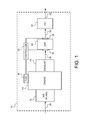
- a vehicle 10 which may be an agricultural work vehicle, a forestry work vehicle or a construction type vehicle utilizing an engine system that includes an air intake 12, an engine 14, a fuel supply system 16 (labeled FUEL in Fig. 1 ), and an exhaust system 18 (labeled EXHAUST in Fig. 1 ).
- Engine 14 has at least one piston reciprocating within an engine block that is connected to a crankshaft for producing a rotary output (not shown). Each piston is movable within a variable volume combustion chamber that receives air for combustion from air intake 12 and fuel from fuel supply system 16. The products of combustion pass through exhaust system 18.
- the engine system additionally includes a diesel particulate filter (DPF) 20 (labeled DPF in Fig. 1 ) and a catalyst 22 (labeled CAT in Fig. 1 ).
- DPF diesel particulate filter
- CAT catalyst
- An air intake flow 24 passes into engine 14 for the purposes of combustion, having an exhaust flow 26 that passes through DPF 20 and a gas flow 28 that continues through catalyst 22 and is exhausted in the form of gas flow 30 to the environment.
- DPF 20 and catalyst 22 may be combined into one unit or catalyst 22 may be positioned at a different location or omitted from the engine system.
- a controller 32 interacts with sensors 34 and 36 as well as fuel supply system 16 to control the flow of fuel and to sense the pressure drop across DPF 20.
- DPF 20 may be regenerated as directed by controller 32 with input of the sensors 34 and 36, each of which provide pressure readings so that the pressure drop across DPF 20 can be calculated by controller 32 based on the difference in pressure measurements between sensors 34 and 36.
- Controller 32 provides input to fuel supply system 16, which may cause engine 14 to change the exhaust temperature flowing through exhaust system 18 to DPF 20, causing a regeneration of DPF 20.
- DPF 20 may be in the form of a wall-flow filter that traps soot with a very high efficiency, even above 90%.
- the soot cake layer has been established within DPF 20, filling the inlet channel walls, the pressure increases across DPF 20 and a soot trapping efficiency of higher than 99% may be achieved.
- a high filtration efficiency DPF 20 also traps ash, which can come from high ash lube oil, excessive oil consumption, and high ash fuels, such as biodiesel. As ash gradually accumulates in DPF 20, the DPF 20 delta pressure signal received by controller 32 at a given soot level will be higher. This behavior is due to ash occupying space in the inlet channels of DPF 20, leaving less surface/volume for soot distribution.
- ash accumulation is generally a slow process.
- Total exhaust system back pressure due to ash starts to become noticeable above 2,500 hours of engine operation for greater than 130 kilowatt applications, and above 1,500 hours of operation for less than 130 kilowatt applications.
- the delta pressure sensor readings increase as a result of the ash loading. Without any compensation for ash loading, the time interval between regenerations starts to decrease since the aftertreatment control system will determine that a DPF 20 regeneration needs to occur based on delta pressure readings.
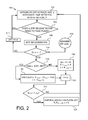
- Method 100 utilized within controller 32, which may be interconnected to other sensors and control systems. Controller 32 may have other functions unrelated or indirectly related to the functions of method 100 of the present invention.
- Method 100 includes a step 102 in which the DPF service age ⁇ , as well as the time between regenerations ⁇ are separately integrated by a process of integration or summing. This summing of the DPF service age ⁇ and this step also keeps track of the time between regenerations ⁇ .
- step 104 a decision is made as to whether DPF 20 requires a regeneration.
- step 104 proceeds back to step 102 but the time continues to be tracked for the DPF service age ⁇ and the time between regenerations ⁇ . If a DPF regeneration needs to take place as decided at step 104, method 100 proceeds to step 106 in which a DPF regeneration cycle is initiated and takes place.
- a predetermined minimum DPF age T is used in step 110 to compare to the DPF service age ⁇ to see if ⁇ is greater than or equal to T. If the integrated DPF service age ⁇ is not greater than or equal to the minimum DPF age T, then method 100 resets the time between regenerations ⁇ to be equal to zero, at step 112 so that it will then start re-accumulating time at step 102. This portion of method of 100 ensures that at least a minimum age for DPF 20 is realized before establishing a service life for DPF 20. In the event that the DPF service age ⁇ exceeds or is equal to the minimum DPF age T, method 100 proceeds to step 114 to determine if a maximum average time ⁇ has been set.
- step 116 If the answer is no, then the maximum average time is set to the most recent time between regenerations ⁇ and ⁇ AVG is also set equal to ⁇ , at step 116. If the maximum average time ⁇ has been previously set, then method 100 proceeds from step 114 to step 118 in which the running average of the time between regeneration is calculated by the equation of ⁇ AVG being set equal to ( ⁇ AVG + ⁇ ) / 2. Then, an end-of-service Life ratio ⁇ is set equal to the running average of time between regenerations ⁇ AVG divided by the maximum average time ⁇ and the time between regenerations ⁇ is set to zero, at step 120.
- Method 100 then proceeds to step 122, in which it is determined whether the end-of-service life ratio ⁇ is less than or equal to the end-of-service life ratio maximum ⁇ L . If the answer is no, then method 100 proceeds to step 102. If the end-of-service life ratio ⁇ is less than or equal to end-of-service life ratio maximum ⁇ L , then method 100 proceeds to step 124 in which an indication is made that service or the replacement of the DPF 20 is necessary. The indication may be in the form of an illuminated warning light on a console supervised by an operator or some other form of communication of the information to the operator of vehicle 10 or to maintenance personnel. Additionally, at step 124, when the service or replacement of DPF 20 takes place, variables are set to zero such as ⁇ , ⁇ AVG , ⁇ , ⁇ , ⁇ .
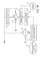
- Method 200 has two variations, which are further explained in Figs. 3B and 3C .
- the variations of method 200 are to be understood to be illustrated in the differences in Figs. 3B and 3C .
- the first variation of method 200 utilizes Figs. 3A and 3B and the second variation of method 200 utilizes Figs. 3A and 3C . Steps that are similar between method 100 and 200 retain the same numbers from method 100 and perform the functions as discussed above.
- step 202 it is determined whether the ash accumulation rate u is greater than zero. If the ash accumulation rate u is not greater than zero, then method 200 proceeds to step 110. If the ash accumulation rate u is greater than zero at step 202, then method 200 proceeds to step 214 and bypasses several steps, since the ash accumulation rate u has been established.
- step 206 DPF 20 ash loading value ⁇ is set by utilizing the service life ratio versus DPF ash loading table depicted in step 204 to thereby determine the ash loading value ⁇ .
- step 208 the ash accumulation rate u is calculated by setting it equal to the ash loading value ⁇ divided by the service age ⁇ value.
- step 210 the maximum DPF service age ⁇ L is calculated by setting it equal to the maximum ash loading value ⁇ L depicted in step 212, which is a predetermined value, divided by the ash accumulation rate u.
- the DPF service age ⁇ is compared to the maximum DPF service age ⁇ L . If the DPF service age ⁇ is greater than or equal to the maximum DPF service age ⁇ L , then method 200 proceeds to step 216. If the DPF service age ⁇ is not greater than or equal to the maximum DPF service age ⁇ L , then method 200 proceeds to step 102.
- an indication is provided to the operator of vehicle 10 or maintenance personnel of vehicle 10 that servicing and/or replacement of DPF 20 is necessary. The indication may be in the form of an illuminated warning light on a console supervised by the operator or some other form of communication of the information to the operator of vehicle 10 or to the maintenance personnel.
- variables are set to zero, such as ⁇ AVG , ⁇ , ⁇ , ⁇ , T, ⁇ , u.
- Step 218 is undertaken upon the completion of step 208 or upon the affirmative answer of the test at step 202.
- the DPF 20 ash loading value ⁇ is calculated by setting it equal to the DPF service age ⁇ times the ash accumulation rate u.
- the comparison is undertaken to see if the ash loading value ⁇ is greater than or equal to maximum ash loading value ⁇ L obtained as a predetermined value, as illustrated in step 212.
- step 216 If the ash loading value ⁇ is greater than or equal to the maximum ash loading value ⁇ L , then method 200 proceeds to step 216 in which the DPF 20 is serviced and/or replaced. If the DPF ash loading value ⁇ is not greater than or equal to the maximum ash loading value ⁇ L , then method 200 proceeds back to step 102.
- Methods 100 and 200 deal with ash that is accumulated in DPF 20 with time, and recognizes the normalized delta pressure readings will tend to increase, leading to more frequent regenerations.
- the increase in the number of regenerations can be tied in direct proportion to the overall average time between regenerations.
- the maximum average time ⁇ is calculated early on in engine and aftertreatment service life. Although it can be calculated from the first several samples of time between regenerations, waiting for DPF age ⁇ to pass a minimum DPF age ⁇ allows there to be ample time for the maximum average time ⁇ to be established and thereby avoid a possible over calculation of the maximum average time between regenerations.
- the end-of-service life ratio ⁇ can be used as an input to an ash loading table to determine the ash loading value ⁇ .
- the ash loading value ⁇ is then used to calculate the ash accumulation rate u.
- Either the DPF service age ⁇ is used as the test, as in Fig. 3B
- the ash loading value ⁇ is used as the test, as in Fig. 3C to determine if it is time to service and/or replace DPF 20, at step 216.
- the present invention provides a statistically based ash model to monitor and verify the ash prediction that is not based on operation hours or fuel consumption history, as utilized in prior art systems. Further, the method is also capable of flagging excessive oil consumption or poor fuel quality that results in excessive loading of DPF 20. Additionally, the present invention reduces the number of DPF regenerations when the DPF 20 is approaching the end-of-service life. The method can also generate an input for a monitor after determining that an ash service warning or engine degradation is occurring or may occur. Yet further, the present invention can compensate for the use of biodiesel, which has a tendency to create additional ash over petroleum based diesel.
Landscapes
- Engineering & Computer Science (AREA)
- Chemical & Material Sciences (AREA)
- Combustion & Propulsion (AREA)
- Mechanical Engineering (AREA)
- General Engineering & Computer Science (AREA)
- Chemical Kinetics & Catalysis (AREA)
- Analytical Chemistry (AREA)
- Processes For Solid Components From Exhaust (AREA)
Applications Claiming Priority (1)
| Application Number | Priority Date | Filing Date | Title |
|---|---|---|---|
| US12/896,102 US8660741B2 (en) | 2010-10-01 | 2010-10-01 | Particulate filter ash loading prediction method and vehicle with same |
Publications (3)
| Publication Number | Publication Date |
|---|---|
| EP2436891A2 true EP2436891A2 (de) | 2012-04-04 |
| EP2436891A3 EP2436891A3 (de) | 2015-06-03 |
| EP2436891B1 EP2436891B1 (de) | 2017-08-02 |
Family
ID=44862508
Family Applications (1)
| Application Number | Title | Priority Date | Filing Date |
|---|---|---|---|
| EP11183348.9A Active EP2436891B1 (de) | 2010-10-01 | 2011-09-29 | Verfahren zur Vorhersage der Aschebelastung eines Partikelfilters und Fahrzeug damit |
Country Status (2)
| Country | Link |
|---|---|
| US (1) | US8660741B2 (de) |
| EP (1) | EP2436891B1 (de) |
Cited By (1)
| Publication number | Priority date | Publication date | Assignee | Title |
|---|---|---|---|---|
| CN110410189A (zh) * | 2019-07-02 | 2019-11-05 | 一汽解放汽车有限公司 | 柴油颗粒过滤器的故障诊断方法、装置、车辆及存储介质 |
Families Citing this family (8)
| Publication number | Priority date | Publication date | Assignee | Title |
|---|---|---|---|---|
| US8935953B2 (en) * | 2013-05-15 | 2015-01-20 | GM Global Technology Operations LLC | Adaptive soot mass estimation in a vehicle exhaust after-treatment device |
| US9371767B2 (en) * | 2013-09-20 | 2016-06-21 | Tenneco Automotive Operating Company Inc. | Soot load determination system |
| US11053835B2 (en) * | 2018-05-10 | 2021-07-06 | Volvo Truck Corporation | Method and system for assessing engine faults |
| US10774722B2 (en) * | 2018-09-04 | 2020-09-15 | Afton Chemical Corporation | Predictive methods for emissions control systems performance |
| CN110849605B (zh) * | 2019-11-18 | 2021-05-18 | 中国重汽集团济南动力有限公司 | 判断堵塞故障程度方法及移除故障程度方法 |
| CN113741196B (zh) * | 2021-09-14 | 2022-04-01 | 江苏海平面数据科技有限公司 | 一种基于车联网大数据的dpf再生周期控制优化方法 |
| CN113944536B (zh) * | 2021-09-30 | 2022-09-09 | 三一汽车起重机械有限公司 | 颗粒捕集器再生的预警方法和装置 |
| CN118309546B (zh) * | 2024-06-07 | 2024-09-03 | 中汽研汽车检验中心(昆明)有限公司 | 高原dpf碳载量预测方法、装置、设备及存储介质 |
Citations (2)
| Publication number | Priority date | Publication date | Assignee | Title |
|---|---|---|---|---|
| US6622480B2 (en) | 2001-02-21 | 2003-09-23 | Isuzu Motors Limited | Diesel particulate filter unit and regeneration control method of the same |
| US20070251214A1 (en) | 2006-04-27 | 2007-11-01 | Hiroaki Nishino | Apparatus for detecting a state of a particulate filter |
Family Cites Families (18)
| Publication number | Priority date | Publication date | Assignee | Title |
|---|---|---|---|---|
| JPH1077826A (ja) * | 1996-09-06 | 1998-03-24 | Nissan Motor Co Ltd | ディーゼルエンジンの黒煙浄化装置 |
| JPH1077827A (ja) * | 1996-09-06 | 1998-03-24 | Nissan Motor Co Ltd | ディーゼルエンジンの黒煙浄化装置 |
| JP3869333B2 (ja) * | 2002-08-12 | 2007-01-17 | ボッシュ株式会社 | 排気ガス浄化装置 |
| US6875249B2 (en) * | 2002-10-08 | 2005-04-05 | Donaldson Company, Inc. | Motor vehicle filter structure having visual indicator of useful life |
| US7581389B2 (en) * | 2004-01-13 | 2009-09-01 | Emcon Technologies Llc | Method and apparatus for monitoring ash accumulation in a particulate filter of an emission abatement assembly |
| JP3938188B2 (ja) * | 2005-05-17 | 2007-06-27 | いすゞ自動車株式会社 | 排気ガス浄化システムの制御方法及び排気ガス浄化システム |
| JP2007002694A (ja) * | 2005-06-22 | 2007-01-11 | Honda Motor Co Ltd | 内燃機関の排気浄化装置 |
| US7607295B2 (en) * | 2005-07-07 | 2009-10-27 | Nissan Motor Co., Ltd. | Particulate accumulation amount estimating system |
| US7677032B2 (en) * | 2005-09-15 | 2010-03-16 | Cummins, Inc. | Apparatus, system, and method for determining the distribution of particulate matter on a particulate filter |
| US7506503B2 (en) * | 2005-09-15 | 2009-03-24 | Cummins, Inc | Apparatus, system, and method for estimating ash accumulation |
| US8384396B2 (en) * | 2006-05-01 | 2013-02-26 | Filter Sensing Technologies, Inc. | System and method for measuring retentate in filters |
| FR2908822A1 (fr) * | 2006-11-17 | 2008-05-23 | Saint Gobain Ct Recherches | Procede de calibrage et de gestion d'une ligne d'echappement comprenant un filtre a particules |
| EP2180933A4 (de) * | 2007-08-03 | 2011-08-10 | Errcive Inc | Pröse körper und verfahren |
| EP2350443B1 (de) * | 2008-10-31 | 2018-10-17 | Filter Sensing Technologies, Inc. | Abgasnachbehandlungsverfahren und -system zur betriebssteuerung eines filters |
| JP4774096B2 (ja) * | 2008-11-17 | 2011-09-14 | 日立建機株式会社 | 作業機械の排気ガス浄化システム |
| US8214135B2 (en) * | 2010-10-01 | 2012-07-03 | Deere & Company | Particulate filter ash loading prediction method and vehicle using same |
| US8577541B2 (en) * | 2010-10-01 | 2013-11-05 | Deere & Company | Particulate filter ash loading prediction method and vehicle using same |
| US8868266B2 (en) * | 2011-08-19 | 2014-10-21 | General Electric Company | Method and system for engine exhaust filter regeneration of a vehicle in a consist |
-
2010
- 2010-10-01 US US12/896,102 patent/US8660741B2/en active Active
-
2011
- 2011-09-29 EP EP11183348.9A patent/EP2436891B1/de active Active
Patent Citations (2)
| Publication number | Priority date | Publication date | Assignee | Title |
|---|---|---|---|---|
| US6622480B2 (en) | 2001-02-21 | 2003-09-23 | Isuzu Motors Limited | Diesel particulate filter unit and regeneration control method of the same |
| US20070251214A1 (en) | 2006-04-27 | 2007-11-01 | Hiroaki Nishino | Apparatus for detecting a state of a particulate filter |
Cited By (2)
| Publication number | Priority date | Publication date | Assignee | Title |
|---|---|---|---|---|
| CN110410189A (zh) * | 2019-07-02 | 2019-11-05 | 一汽解放汽车有限公司 | 柴油颗粒过滤器的故障诊断方法、装置、车辆及存储介质 |
| CN110410189B (zh) * | 2019-07-02 | 2020-12-04 | 一汽解放汽车有限公司 | 柴油颗粒过滤器的故障诊断方法、装置、车辆及存储介质 |
Also Published As
| Publication number | Publication date |
|---|---|
| EP2436891A3 (de) | 2015-06-03 |
| EP2436891B1 (de) | 2017-08-02 |
| US20120083966A1 (en) | 2012-04-05 |
| US8660741B2 (en) | 2014-02-25 |
Similar Documents
| Publication | Publication Date | Title |
|---|---|---|
| US8214135B2 (en) | Particulate filter ash loading prediction method and vehicle using same | |
| EP2436900B1 (de) | Verfahren zur Vorhersage der Aschebelastung eines Partikelfilters und Fahrzeug damit | |
| EP2436891B1 (de) | Verfahren zur Vorhersage der Aschebelastung eines Partikelfilters und Fahrzeug damit | |
| EP2436892B1 (de) | Verfahren zur Prognose der Ladung von Partikelfilterasche und Fahrzeug damit | |
| US7758676B2 (en) | Adaptive learning method for clean particulate filter pressure drop | |
| EP1541829B1 (de) | Verfahren zur Aktivierung der Regeneration eines Partikelfilters auf Basis von der Schätzung des in dem Partikelfiter angesammelten Partikelmenge | |
| CN101889131B (zh) | 过滤器再生系统的异常诊断系统以及异常诊断方法 | |
| US20120288410A1 (en) | Exhaust gas purification apparatus for engine | |
| CN112761766A (zh) | 一种dpf碳载量估算方法及系统 | |
| US10577998B2 (en) | Method for controlling a regeneration of a particle filter of an internal combustion engine | |
| US8011179B2 (en) | Method and system for maintaining aftertreatment efficiency | |
| US8620597B2 (en) | Particulate filter service life prediction | |
| Sappok et al. | On-board particulate filter failure prevention and failure diagnostics using radio frequency sensing | |
| KR101473803B1 (ko) | 배기가스 저감장치의 제어방법 | |
| KR101551083B1 (ko) | 자동차용 dpf 시스템 고장 진단 방법 | |
| CN115667680A (zh) | 过滤器状态检测装置 | |
| JP5366015B2 (ja) | 内燃機関の排気浄化装置 | |
| JP7471198B2 (ja) | 排ガス浄化システムおよび排ガス浄化装置の再生方法 | |
| JP4403915B2 (ja) | ディーゼルエンジンの排気後処理装置 | |
| JP7302541B2 (ja) | 排気処理システム | |
| EP3771810A1 (de) | Abgasbehandlungssystem | |
| US10132262B2 (en) | Methods for optimizing exhaust gas system regeneration and cleaning | |
| CN116906161A (zh) | Dpf灰分在线监测方法及系统 | |
| Rose et al. | Impact of FAME Content on Regeneration Frequency of Diesel Particulate Filters (DPFs) |
Legal Events
| Date | Code | Title | Description |
|---|---|---|---|
| PUAI | Public reference made under article 153(3) epc to a published international application that has entered the european phase |
Free format text: ORIGINAL CODE: 0009012 |
|
| AK | Designated contracting states |
Kind code of ref document: A2 Designated state(s): AL AT BE BG CH CY CZ DE DK EE ES FI FR GB GR HR HU IE IS IT LI LT LU LV MC MK MT NL NO PL PT RO RS SE SI SK SM TR |
|
| AX | Request for extension of the european patent |
Extension state: BA ME |
|
| PUAL | Search report despatched |
Free format text: ORIGINAL CODE: 0009013 |
|
| AK | Designated contracting states |
Kind code of ref document: A3 Designated state(s): AL AT BE BG CH CY CZ DE DK EE ES FI FR GB GR HR HU IE IS IT LI LT LU LV MC MK MT NL NO PL PT RO RS SE SI SK SM TR |
|
| AX | Request for extension of the european patent |
Extension state: BA ME |
|
| RIC1 | Information provided on ipc code assigned before grant |
Ipc: F01N 9/00 20060101AFI20150428BHEP |
|
| 17P | Request for examination filed |
Effective date: 20151203 |
|
| RBV | Designated contracting states (corrected) |
Designated state(s): AL AT BE BG CH CY CZ DE DK EE ES FI FR GB GR HR HU IE IS IT LI LT LU LV MC MK MT NL NO PL PT RO RS SE SI SK SM TR |
|
| GRAP | Despatch of communication of intention to grant a patent |
Free format text: ORIGINAL CODE: EPIDOSNIGR1 |
|
| INTG | Intention to grant announced |
Effective date: 20170224 |
|
| GRAS | Grant fee paid |
Free format text: ORIGINAL CODE: EPIDOSNIGR3 |
|
| GRAA | (expected) grant |
Free format text: ORIGINAL CODE: 0009210 |
|
| AK | Designated contracting states |
Kind code of ref document: B1 Designated state(s): AL AT BE BG CH CY CZ DE DK EE ES FI FR GB GR HR HU IE IS IT LI LT LU LV MC MK MT NL NO PL PT RO RS SE SI SK SM TR |
|
| REG | Reference to a national code |
Ref country code: GB Ref legal event code: FG4D |
|
| REG | Reference to a national code |
Ref country code: CH Ref legal event code: EP Ref country code: AT Ref legal event code: REF Ref document number: 914746 Country of ref document: AT Kind code of ref document: T Effective date: 20170815 |
|
| REG | Reference to a national code |
Ref country code: IE Ref legal event code: FG4D |
|
| REG | Reference to a national code |
Ref country code: DE Ref legal event code: R096 Ref document number: 602011040090 Country of ref document: DE |
|
| REG | Reference to a national code |
Ref country code: NL Ref legal event code: MP Effective date: 20170802 |
|
| REG | Reference to a national code |
Ref country code: AT Ref legal event code: MK05 Ref document number: 914746 Country of ref document: AT Kind code of ref document: T Effective date: 20170802 |
|
| REG | Reference to a national code |
Ref country code: LT Ref legal event code: MG4D |
|
| PG25 | Lapsed in a contracting state [announced via postgrant information from national office to epo] |
Ref country code: FI Free format text: LAPSE BECAUSE OF FAILURE TO SUBMIT A TRANSLATION OF THE DESCRIPTION OR TO PAY THE FEE WITHIN THE PRESCRIBED TIME-LIMIT Effective date: 20170802 Ref country code: HR Free format text: LAPSE BECAUSE OF FAILURE TO SUBMIT A TRANSLATION OF THE DESCRIPTION OR TO PAY THE FEE WITHIN THE PRESCRIBED TIME-LIMIT Effective date: 20170802 Ref country code: LT Free format text: LAPSE BECAUSE OF FAILURE TO SUBMIT A TRANSLATION OF THE DESCRIPTION OR TO PAY THE FEE WITHIN THE PRESCRIBED TIME-LIMIT Effective date: 20170802 Ref country code: AT Free format text: LAPSE BECAUSE OF FAILURE TO SUBMIT A TRANSLATION OF THE DESCRIPTION OR TO PAY THE FEE WITHIN THE PRESCRIBED TIME-LIMIT Effective date: 20170802 Ref country code: NO Free format text: LAPSE BECAUSE OF FAILURE TO SUBMIT A TRANSLATION OF THE DESCRIPTION OR TO PAY THE FEE WITHIN THE PRESCRIBED TIME-LIMIT Effective date: 20171102 Ref country code: SE Free format text: LAPSE BECAUSE OF FAILURE TO SUBMIT A TRANSLATION OF THE DESCRIPTION OR TO PAY THE FEE WITHIN THE PRESCRIBED TIME-LIMIT Effective date: 20170802 Ref country code: NL Free format text: LAPSE BECAUSE OF FAILURE TO SUBMIT A TRANSLATION OF THE DESCRIPTION OR TO PAY THE FEE WITHIN THE PRESCRIBED TIME-LIMIT Effective date: 20170802 |
|
| PG25 | Lapsed in a contracting state [announced via postgrant information from national office to epo] |
Ref country code: GR Free format text: LAPSE BECAUSE OF FAILURE TO SUBMIT A TRANSLATION OF THE DESCRIPTION OR TO PAY THE FEE WITHIN THE PRESCRIBED TIME-LIMIT Effective date: 20171103 Ref country code: LV Free format text: LAPSE BECAUSE OF FAILURE TO SUBMIT A TRANSLATION OF THE DESCRIPTION OR TO PAY THE FEE WITHIN THE PRESCRIBED TIME-LIMIT Effective date: 20170802 Ref country code: RS Free format text: LAPSE BECAUSE OF FAILURE TO SUBMIT A TRANSLATION OF THE DESCRIPTION OR TO PAY THE FEE WITHIN THE PRESCRIBED TIME-LIMIT Effective date: 20170802 Ref country code: PL Free format text: LAPSE BECAUSE OF FAILURE TO SUBMIT A TRANSLATION OF THE DESCRIPTION OR TO PAY THE FEE WITHIN THE PRESCRIBED TIME-LIMIT Effective date: 20170802 Ref country code: BG Free format text: LAPSE BECAUSE OF FAILURE TO SUBMIT A TRANSLATION OF THE DESCRIPTION OR TO PAY THE FEE WITHIN THE PRESCRIBED TIME-LIMIT Effective date: 20171102 Ref country code: IS Free format text: LAPSE BECAUSE OF FAILURE TO SUBMIT A TRANSLATION OF THE DESCRIPTION OR TO PAY THE FEE WITHIN THE PRESCRIBED TIME-LIMIT Effective date: 20171202 Ref country code: ES Free format text: LAPSE BECAUSE OF FAILURE TO SUBMIT A TRANSLATION OF THE DESCRIPTION OR TO PAY THE FEE WITHIN THE PRESCRIBED TIME-LIMIT Effective date: 20170802 |
|
| PG25 | Lapsed in a contracting state [announced via postgrant information from national office to epo] |
Ref country code: RO Free format text: LAPSE BECAUSE OF FAILURE TO SUBMIT A TRANSLATION OF THE DESCRIPTION OR TO PAY THE FEE WITHIN THE PRESCRIBED TIME-LIMIT Effective date: 20170802 Ref country code: CZ Free format text: LAPSE BECAUSE OF FAILURE TO SUBMIT A TRANSLATION OF THE DESCRIPTION OR TO PAY THE FEE WITHIN THE PRESCRIBED TIME-LIMIT Effective date: 20170802 Ref country code: DK Free format text: LAPSE BECAUSE OF FAILURE TO SUBMIT A TRANSLATION OF THE DESCRIPTION OR TO PAY THE FEE WITHIN THE PRESCRIBED TIME-LIMIT Effective date: 20170802 |
|
| REG | Reference to a national code |
Ref country code: CH Ref legal event code: PL |
|
| REG | Reference to a national code |
Ref country code: DE Ref legal event code: R097 Ref document number: 602011040090 Country of ref document: DE |
|
| PG25 | Lapsed in a contracting state [announced via postgrant information from national office to epo] |
Ref country code: SK Free format text: LAPSE BECAUSE OF FAILURE TO SUBMIT A TRANSLATION OF THE DESCRIPTION OR TO PAY THE FEE WITHIN THE PRESCRIBED TIME-LIMIT Effective date: 20170802 Ref country code: EE Free format text: LAPSE BECAUSE OF FAILURE TO SUBMIT A TRANSLATION OF THE DESCRIPTION OR TO PAY THE FEE WITHIN THE PRESCRIBED TIME-LIMIT Effective date: 20170802 Ref country code: IT Free format text: LAPSE BECAUSE OF FAILURE TO SUBMIT A TRANSLATION OF THE DESCRIPTION OR TO PAY THE FEE WITHIN THE PRESCRIBED TIME-LIMIT Effective date: 20170802 Ref country code: MC Free format text: LAPSE BECAUSE OF FAILURE TO SUBMIT A TRANSLATION OF THE DESCRIPTION OR TO PAY THE FEE WITHIN THE PRESCRIBED TIME-LIMIT Effective date: 20170802 Ref country code: SM Free format text: LAPSE BECAUSE OF FAILURE TO SUBMIT A TRANSLATION OF THE DESCRIPTION OR TO PAY THE FEE WITHIN THE PRESCRIBED TIME-LIMIT Effective date: 20170802 |
|
| PLBE | No opposition filed within time limit |
Free format text: ORIGINAL CODE: 0009261 |
|
| STAA | Information on the status of an ep patent application or granted ep patent |
Free format text: STATUS: NO OPPOSITION FILED WITHIN TIME LIMIT |
|
| REG | Reference to a national code |
Ref country code: IE Ref legal event code: MM4A |
|
| REG | Reference to a national code |
Ref country code: BE Ref legal event code: MM Effective date: 20170930 |
|
| PG25 | Lapsed in a contracting state [announced via postgrant information from national office to epo] |
Ref country code: LU Free format text: LAPSE BECAUSE OF NON-PAYMENT OF DUE FEES Effective date: 20170929 |
|
| REG | Reference to a national code |
Ref country code: FR Ref legal event code: ST Effective date: 20180531 |
|
| 26N | No opposition filed |
Effective date: 20180503 |
|
| PG25 | Lapsed in a contracting state [announced via postgrant information from national office to epo] |
Ref country code: CH Free format text: LAPSE BECAUSE OF NON-PAYMENT OF DUE FEES Effective date: 20170930 Ref country code: LI Free format text: LAPSE BECAUSE OF NON-PAYMENT OF DUE FEES Effective date: 20170930 Ref country code: IE Free format text: LAPSE BECAUSE OF NON-PAYMENT OF DUE FEES Effective date: 20170929 |
|
| PG25 | Lapsed in a contracting state [announced via postgrant information from national office to epo] |
Ref country code: SI Free format text: LAPSE BECAUSE OF FAILURE TO SUBMIT A TRANSLATION OF THE DESCRIPTION OR TO PAY THE FEE WITHIN THE PRESCRIBED TIME-LIMIT Effective date: 20170802 Ref country code: FR Free format text: LAPSE BECAUSE OF NON-PAYMENT OF DUE FEES Effective date: 20171002 Ref country code: BE Free format text: LAPSE BECAUSE OF NON-PAYMENT OF DUE FEES Effective date: 20170930 |
|
| PG25 | Lapsed in a contracting state [announced via postgrant information from national office to epo] |
Ref country code: MT Free format text: LAPSE BECAUSE OF NON-PAYMENT OF DUE FEES Effective date: 20170929 |
|
| PG25 | Lapsed in a contracting state [announced via postgrant information from national office to epo] |
Ref country code: HU Free format text: LAPSE BECAUSE OF FAILURE TO SUBMIT A TRANSLATION OF THE DESCRIPTION OR TO PAY THE FEE WITHIN THE PRESCRIBED TIME-LIMIT; INVALID AB INITIO Effective date: 20110929 |
|
| PG25 | Lapsed in a contracting state [announced via postgrant information from national office to epo] |
Ref country code: CY Free format text: LAPSE BECAUSE OF NON-PAYMENT OF DUE FEES Effective date: 20170802 |
|
| PG25 | Lapsed in a contracting state [announced via postgrant information from national office to epo] |
Ref country code: MK Free format text: LAPSE BECAUSE OF FAILURE TO SUBMIT A TRANSLATION OF THE DESCRIPTION OR TO PAY THE FEE WITHIN THE PRESCRIBED TIME-LIMIT Effective date: 20170802 |
|
| PG25 | Lapsed in a contracting state [announced via postgrant information from national office to epo] |
Ref country code: TR Free format text: LAPSE BECAUSE OF FAILURE TO SUBMIT A TRANSLATION OF THE DESCRIPTION OR TO PAY THE FEE WITHIN THE PRESCRIBED TIME-LIMIT Effective date: 20170802 |
|
| PG25 | Lapsed in a contracting state [announced via postgrant information from national office to epo] |
Ref country code: PT Free format text: LAPSE BECAUSE OF FAILURE TO SUBMIT A TRANSLATION OF THE DESCRIPTION OR TO PAY THE FEE WITHIN THE PRESCRIBED TIME-LIMIT Effective date: 20170802 |
|
| PG25 | Lapsed in a contracting state [announced via postgrant information from national office to epo] |
Ref country code: AL Free format text: LAPSE BECAUSE OF FAILURE TO SUBMIT A TRANSLATION OF THE DESCRIPTION OR TO PAY THE FEE WITHIN THE PRESCRIBED TIME-LIMIT Effective date: 20170802 |
|
| PGFP | Annual fee paid to national office [announced via postgrant information from national office to epo] |
Ref country code: GB Payment date: 20230927 Year of fee payment: 13 |
|
| PGFP | Annual fee paid to national office [announced via postgrant information from national office to epo] |
Ref country code: DE Payment date: 20230821 Year of fee payment: 13 |