EP2436853A2 - Halteteil für einen Drehknauf - Google Patents
Halteteil für einen Drehknauf Download PDFInfo
- Publication number
- EP2436853A2 EP2436853A2 EP11007553A EP11007553A EP2436853A2 EP 2436853 A2 EP2436853 A2 EP 2436853A2 EP 11007553 A EP11007553 A EP 11007553A EP 11007553 A EP11007553 A EP 11007553A EP 2436853 A2 EP2436853 A2 EP 2436853A2
- Authority
- EP
- European Patent Office
- Prior art keywords
- holding part
- profile cylinder
- knob
- parts
- rotary knob
- Prior art date
- Legal status (The legal status is an assumption and is not a legal conclusion. Google has not performed a legal analysis and makes no representation as to the accuracy of the status listed.)
- Granted
Links
Images



Classifications
-
- E—FIXED CONSTRUCTIONS
- E05—LOCKS; KEYS; WINDOW OR DOOR FITTINGS; SAFES
- E05B—LOCKS; ACCESSORIES THEREFOR; HANDCUFFS
- E05B47/00—Operating or controlling locks or other fastening devices by electric or magnetic means
- E05B47/06—Controlling mechanically-operated bolts by electro-magnetically-operated detents
- E05B47/0611—Cylinder locks with electromagnetic control
- E05B47/0615—Cylinder locks with electromagnetic control operated by handles, e.g. by knobs
Definitions
- the invention relates to a holding part for a knob of a Knaufzylinders and a mounting method therefor.
- Rotary knobs of Knaufzylindern are known to be used, when activated to control a recorded in an associated profile cylinder of a wing lock actuator to rotatably connect a cam of the profile cylinder with the rotary knob. After completion of the activation, the actuator is switched off. Furthermore, a reader is integrated, which handles the readout example of code cards by way of example in the form of transponder cards. The respective card is created or approximated to the knob of the rotary knob and contains authorization data. These data are read out by the reader and checked for permission to open the respective sash. If the test is successful, the rotary knob is activated and the sash can be unlocked and opened with the aid of the rotary knob.
- the object of the invention is to improve the mounting of such a knob.
- a holding part which is designed to be inserted into a rotary knob. It is also designed to receive and hold all other, arranged in the knob parts and at the same time to be attached to a profile cylinder. This provides the ability to mount the parts regardless of the attachment to the profile cylinder can.
- a module that can be attached as a whole to the profile cylinder. This simplifies the assembly enormously.
- the holding part further comprises two, preferably electrically isolated from each other receiving spaces in which two of the parts are received in a stationary manner. This solution protects the recorded parts to the outside from mechanical influences and thus from damage. The electrical insulation also allows the parts to be protected against unwanted currents.
- the holding part preferably has first fixing portions which are designed to lock a respective one of the parts at the same time as terminating insertion into the holding part.
- the locking can be done for example by means of jamming and / or Verrastens.
- the holding part may have a second attachment portion which is designed to fasten the holding part on a side facing the knob of the profile cylinder. This provides the ability to attach the knob not on the profile cylinder but on the holding part can. Apart from that, the knob does not have to be formed on the inside to hold the male parts, for example, it can have smooth walls on the inside.
- the second attachment portion preferably has peripherally, in cross-section, radially protruding latching projections, which engage behind an associated latching groove of the profile cylinder. This is a special easy installation is because it can be dispensed with additional locking means such as screws.
- the holding part preferably also has a positioning aid, due to which the holding part is designed so that it can only be placed in the positions on a corresponding placement aid of the profile cylinder, that the holding part can be finally attached to the profile cylinder. This reduces the probability of incorrect installation or even prevents them.
- the holding part preferably also has at least one cable guide. This offers the advantage of laying the cables to be laid so that they neither scrub somewhere nor are in the way during assembly.
- the holding part further preferably comprises at least one locking portion, by means of which a respective one of the parts is locked at the same time after its insertion into the holding part. Ie. the assembly of this part requires only the insertion in the holding part, which makes the installation very easy.
- a provided with such a holding part rotary knob is freely rotatably arranged to a cam of a profile cylinder and activated so that the knob for the time of activation supplied in the profile cylinder actuator with energy, so that it can rotate with him itchationswirkverbundenen cam.
- FIG. 1 shows a rotary knob 2 according to an embodiment of the invention in two views.
- the rotary knob 2 comprises a housing 10 in which all other components of the rotary knob 2 are accommodated.
- the housing 10 is closed by means of a light ring 3 and a cover ring 4 arranged thereon.
- the housing of the outer circumference preferably has recessed grips 11, one of which is provided with a reference numeral.
- FIG. 1b shows the knob 2 without light ring 3 and cover 4.
- a holding part 100 is used in the housing 10 mainly a holding part 100 is used.
- the holding part 100 is designed to hold all other components arranged in the housing 10 and thus forms a complete insertion module with these components.
- the front side of a first board 21 of a reader 20 is arranged, it has substantially the shape of a circular disc and is held with its outer circumferential side edge 23 in corresponding locking hooks 101 of the holding part 100.
- the latching hooks 101 are preferably designed so that they each have a parallel to the side edge 23 formed groove 102 to the side edge 23, in which the board 21 is held securely.
- the latching hooks 101 preferably additionally clamp the circuit board 21 between them, which improves the fixation of the circuit board 21 in the holding part 100.
- the board 21 has an unspecified hole, through which a luminous element 24 emits light in the direction of the aforementioned luminous ring 3 by way of example in the form of an SMD LED.
- the light ring 3 serves to distribute this light.
- At the end of the light ring 3 facing the board 21 has a coupled to the other reader 20 antenna 22, which is designed, for example, to read data from a transponder code card can.
- FIG. 2a shows the holding part 100 without housing 10 and with a flange 51 of a profiled cylinder 50 shown later in the outer periphery preferably has a passage opening 103 through which a contact tongue 25 of the reader 20 protrudes beyond the outer periphery of the holding body 100 and preferably resiliently is formed or stored.
- This allows the reader 20 to be coupled to the preferably metallic housing 10.
- This coupling is advantageously used for the electromagnetic shielding of the reader 20.
- the contact tongue 25 is in this case applied to a second circuit board 26 of the reader 20, which is to be recognized as a starting point, and is coupled accordingly.
- the holding part 100 further has a mounting recess 104 on the outside. As can be seen, in the region of this recess 104 two connection cable 28 of the reader 20 coupled to connector parts 27 and inserted into this, which are also mounted on the board 26.
- the cables 28 are used to connect an actuator not described in detail in the profile cylinder 50, which rotatably when energized the rotary knob 2 with the later specified locking bit 58 of the profile cylinder 50.
- the mounting recess 104 gives the installer the ability to couple the connection cable 28 with the associated connector part 27 can.
- connection cables 28 are not damaged when the holding part 100 is pushed into the housing 10, they are pressed into the interior of the holding part 100 by means of a cable guide 105.
- connection part 29 of the reader 20 and, as an indication, a connection line 41 coupled thereto, of a power supply 40 specified in more detail later, are accessible.
- the mounting opening 106 is analogous to the mounting recess 104 now the possibility that a fitter can couple the connecting line 41 with the reader 20 to the reader 20 itself and to be able to provide the aforementioned actuator with energy.
- FIG. 2b shows the holding part 100 from the back and without flange 51.
- the mounting recess 104 and the mounting hole 106 including the aforementioned wiring can be seen.
- the board 26 is easier to see.
- FIG. 3 shows the holding part 100 in two exploded views.
- the power supply 40 is shown, which is coupled via the connection lines 41 to the connection part 29.
- the energy supply 40 is designed as a battery or accumulator.
- the holding part 100 preferably has two mutually separate receiving spaces 113, 114 for the power supply 40 and the reader 20. So that the energy supply 40 can not easily move out of the receiving space 113, two latching projections 110 facing upwards are formed.
- the latching projections 110 are preferably resilient in order to facilitate the insertion of the power supply 40 into the receiving space 113.
- a passage opening 108 in the form of a slot-like recess is formed here between the latching projections 110.
- cable clamps 109 are formed, which clamp the connection lines 41 and mechanically protect them against the outside of the holding part 100.
- a cable recess 107 is also formed. This serves to insert the connection cable 28.
- the reader 20 is taken with its board 26 in the receiving space 114 of the holding part 100.
- the holding part 100 has two mutually opposite receiving grooves 115, of which only the front neck can be seen.
- the board 26 is inserted with their side edges 31 in the grooves 115. Furthermore, the connection lines 41 can be seen.
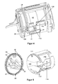
- FIG. 4 again shows a different view of the holding part 100.
- the guide of the connecting lines 41 can be seen particularly well.
- they pass through the passage opening 108 to the outside, under the cable clamps 109 along the outer contour of the energy supply 40 in the direction of the connection part 29.
- FIG. 5 shows the holding member 100 with respect to the attachment to the aforementioned profile cylinder 50.
- the profile cylinder 50 is shown here by means of its flange 51, which serves to attach the holding member 100 on the profile cylinder 51. Both parts 51, 100 are shown from their sides facing each other.
- the flange 51 preferably also has a cable recess 52, which is formed almost mirror-inverted to the cable recess 107 of the holding part 100 in the mounting position. This results in a completely closed cable channel 52, 107, in which the connection cable 28, not shown here come to rest. They run from the receiving space 114 coming along the cable channel 52, 107 to approximately the middle of the flange 51.
- the flange 51 further comprises here four mounting holes 53 in the form of countersunk holes, via which the flange 51 is screwed to the other profile cylinder 50.
- the holding part 100 In order to fix the holding part 100 to the flange 51, it has four circumferentially preferably uniformly distributed, seen in cross-section, radially protruding locking projections 112. These engage behind a suggestively opposite, opposite internal receiving groove as a latching groove 57 of the flange 51. To place the holding part 100 for this latching engagement on the flange 51, this has at appropriate points Einsetzaus traditions 56, along these the latching projections 112 in the latching groove 57th can be moved into it.
- the holding part 100 is now rotated on the flange 51 about an axis parallel to the mounting direction of the holding part 100 until the latching projections 112 are no longer in the region of the insertion recesses 56.
- holding part 100 and flange 51 preferably have a positioning aid.
- This consists here of a positioning pin 111 by way of example on the holding part 100, which protrudes in the direction of flange 51 with a certain amount.
- the flange 51 has at a corresponding point a groove-like positioning recess 55.
- FIG. 6 shows a knob cylinder 1 according to an embodiment of the invention. It comprises the aforementioned profile cylinder 50 with cam 58 and forend 59. On one hand, the flange 51 is attached to the other profile cylinder 50. And on the flange 51 of the knob 2 is advantageously mounted alone on its not visible here holding part 100.
- the positioning elements 111, 55 may be formed on the other part.
- a positioning aid can be realized instead of the pin-groove combination 56, 112 and an uneven distribution of the locking projections 112 and the Einsetzaus traditions 56 so that there is only a single possible Aufsetzposition.
- the locking groove 57 is closed to the direction of rotation of the holding part 100 facing away from the Einsetzaus traditions 56, so that the rotation can only take place in one direction.
- the flange 51 may be formed integrally with the other profile cylinder 50.
- the invention provides an enormously easy to install rotary knob. 2
Landscapes
- Physics & Mathematics (AREA)
- Electromagnetism (AREA)
- Mechanical Control Devices (AREA)
- Clamps And Clips (AREA)
- Snaps, Bayonet Connections, Set Pins, And Snap Rings (AREA)
Abstract
Description
- Die Erfindung betrifft ein Halteteil für einen Drehknauf eines Knaufzylinders und ein Montageverfahren dafür.
- Drehknäufe von Knaufzylindern werden bekanntermaßen eingesetzt, bei Aktivierung einen in einem zugeordneten Profilzylinder eines Flügelschlosses aufgenommenen Aktor anzusteuern, einen Schließbart des Profilzylinders mit dem Drehknauf rotationswirkzuverbinden. Nach Beenden der Aktivierung wird der Aktor abgeschaltet. Ferner ist ein Leser integriert, der das Auslesen beispielsweise von Codekarten exemplarisch in Form von Transponderkarten erledigt. Die jeweilige Karte wird an den Leser des Drehknaufs angelegt oder an ihn angenähert und beinhaltet Berechtigungsdaten. Diese Daten werden vom Leser ausgelesen und auf Berechtigung, den jeweiligen Flügel öffnen zu dürfen, geprüft. Ist die Prüfung erfolgreich, wird der Drehknauf aktiviert, und der Flügel kann mithilfe des Drehknaufs entriegelt und damit geöffnet werden.
- D. h. im Drehknauf sind zumindest zwei Teile, nämlich die Energieversorgung und der Leser, integriert.
- Aufgabe der Erfindung ist es, die Montage solch eines Drehknaufs zu verbessern.
- Diese Aufgabe wird durch den Gegenstand der Ansprüche 1 und 9 gelöst. Vorteilhafte Weiterbildungen der Erfindung sind in den Unteransprüchen angegeben.
- Erfindungsgemäß ist ein Halteteil vorgesehen, das gestaltet ist, in einen Drehknauf eingeschoben zu werden. Es ist zudem gestaltet, alle sonstigen, im Drehknauf angeordneten Teile aufzunehmen und zu halten und gleichzeitig an einem Profilzylinder befestigt zu werden. Dies bietet die Möglichkeit, die Teile unabhängig von der Anbringung am Profilzylinder montieren zu können. Zudem entsteht durch das Halteteil in Verbindung mit den aufgenommenen Teilen ein Modul, das als Ganzes am Profilzylinder befestigt werden kann. Dies vereinfacht die Montage enorm. Das Halteteil weist ferner zwei, vorzugsweise elektrisch voneinander isolierte Aufnahmeräume auf, in die zwei der Teile ortsfest aufgenommen sind. Diese Lösung schützt die aufgenommenen Teile nach außen vor mechanischen Einflüssen und damit vor Beschädigungen. Die elektrische Isolation erlaubt zudem den Schutz der Teile gegen ungewollte Ströme.
- Das Halteteil weist vorzugsweise erste Befestigungsabschnitte auf, die gestaltet sind, ein jeweiliges der Teile bei Beenden eines Einsetzens in das Halteteil zugleich zu arretieren. Die Arretierung kann beispielsweise mittels Verklemmens und/oder Verrastens erfolgen.
- Das Halteteil kann einen zweiten Befestigungsabschnitt aufweisen, der gestaltet ist, das Halteteil an einer dem Drehknauf zugewandten Seite des Profilzylinders zu befestigen. Dies bietet die Möglichkeit, den Drehknauf nicht am Profilzylinder sondern am Halteteil befestigen zu können. Abgesehen davon muss der Drehknauf innenseitig nicht zum Halten der aufzunehmenden Teile ausgebildet werden, er kann beispielsweise innen glatte Wandungen aufweisen.
- Der zweite Befestigungsabschnitt weist vorzugsweise im Querschnitt umfangsseitig, radial hervorstehende Rastvorsprünge auf, die eine zugehörige Rastnut des Profilzylinders hintergreifen. Dies stellt eine besonders einfache Montage dar, da auf zusätzliche Arretierungsmittel wie Schrauben etc. verzichtet werden kann.
- Das Halteteil weist vorzugsweise ferner eine Positionierhilfe auf, aufgrund der das Halteteil nur in den Positionen auf eine korrespondierende Aufsetzhilfe des Profilzylinders aufsetzbar gestaltet ist, dass das Halteteil endgültig am Profilzylinder befestigt werden kann. Dies verringert die Wahrscheinlichkeit einer fehlerhaften Montage bzw. verhindert sie gar.
- Das Halteteil weist vorzugsweise ferner zumindest eine Kabelführung auf. Dies bietet den Vorteil, die zu verlegenden Leitungen so zu verlegen, dass sie weder irgendwo scheuern noch bei der Montage im Wege sind.
- Das Halteteil umfasst ferner vorzugsweise zumindest einen Arretierabschnitt, mittels dessen ein jeweiliges der Teile nach dessen Einsetzen in das Halteteil zugleich arretiert wird. D. h. die Montage dieses Teils erfordert lediglich das Einsetzen in das Halteteil, was die Montage sehr einfach macht.
- Ein mit solch einem Halteteil versehener Drehknauf ist zu einem Schließbart eines Profilzylinders frei rotierbar angeordnet und derart aktivierbar, dass der Drehknauf für die Zeit der Aktivierung einen im Profilzylinder angeordneten Aktor mit Energie versorgt, sodass dieser den mit ihm rotationswirkverbundenen Schließbart drehen kann.
- Weitere Merkmale und Vorteile der Erfindung ergeben sich aus der nachfolgenden Beschreibung bevorzugter Ausführungsformen. Es zeigen:
- Figur 1
- einen Drehknauf gemäß einer Ausführungsform der Erfindung in zwei Ansichten,
- Figur 2
- das Halteteil des Drehknaufs von
Figur 1 und in zwei Ansichten, - Figur 3
- das Halteteil von
Figur 2 in zwei Explosionsansichten, - Figur 4
- eine andere Ansicht des Halteteils von
Figur 2 , - Figur 5
- das Halteteil hinsichtlich der Anbringung an einem Profilzylinder,
- Figur 6
- einen Knaufzylinder gemäß einer Ausführungsform der Erfindung.
-
Figur 1 zeigt einen Drehknauf 2 gemäß einer Ausführungsform der Erfindung in zwei Ansichten. Wie inFigur 1 a dargestellt, umfasst der Drehknauf 2 ein Gehäuse 10, in dem alle anderen Komponenten des Drehknaufs 2 aufgenommen sind. An einer dem hier nicht dargestellten Profilzylinder 50 abgewandten, hier nach vorne weisenden Seite ist das Gehäuse 10 mittels eines Leuchtrings 3 und eines darauf angeordneten Abdeckrings 4 abgeschlossen. Zum Drehen des Drehknaufs 2 weist dessen Gehäuse außenumfänglich vorzugsweise Griffmulden 11 auf, von denen eine mit einem Bezugszeichen versehen ist. -
Figur 1b zeigt den Drehknauf 2 ohne Leuchtring 3 und Abdeckring 4. Hier ist zu erkennen, dass im Gehäuse 10 hauptsächlich ein Halteteil 100 eingesetzt ist. Das Halteteil 100 ist gestaltet, alle anderen, im Gehäuse 10 angeordneten Komponenten zu halten und bildet mit diesen Komponenten also ein komplettes Einsetzmodul. - Vorderseitig ist eine erste Platine 21 eines Lesers 20 angeordnet, Sie hat im Wesentlichen die Form einer kreisrunden Scheibe und ist mit ihrem außenumfänglichen Seitenrand 23 in korrespondierenden Rasthaken 101 des Halteteils 100 gehalten. Die Rasthaken 101 sind vorzugsweise so ausgebildet, dass sie zum Seitenrand 23 hin jeweils eine parallel zum Seitenrand 23 ausgebildete Nut 102 aufweisen, in der die Platine 21 sicher gehalten ist. Zudem klemmen die Rasthaken 101 die Platine 21 vorzugsweise zusätzlich zwischen sich ein, was die Fixierung der Platine 21 im Halteteil 100 verbessert. In der Mitte weist die Platine 21 ein nicht bezeichnetes Loch auf, durch das hindurch ein Leuchtelement 24 beispielhaft in Form einer SMD-LED Licht in Richtung vorgenannten Leuchtring 3 emittiert. Der Leuchtring 3 dient der Verteilung dieses Lichts. An der dem Leuchtring 3 zugewandten Stirnseite weist die Platine 21 eine mit dem sonstigen Leser 20 gekoppelte Antenne 22 auf, die beispielsweise ausgelegt ist, um Daten einer Transponder-Codekarte auslesen zu können.
-
Figur 2a zeigt das Halteteil 100 ohne Gehäuse 10 und mit einem Flansch 51 eines später näher dargestellten Profilzylinders 50 Das Halteteil 100 weist außenumfänglich vorzugsweise eine Durchtrittsöffnung 103 auf, durch die hindurch eine Kontaktzunge 25 des Lesers 20 hindurch nach über den Außenumfang des Haltekörpers 100 hervorsteht und vorzugsweise federnd ausgebildet bzw. gelagert ist. Dies ermöglicht, den Leser 20 mit dem vorzugsweise metallischen Gehäuse 10 zu koppeln. Diese Kopplung dient vorteilhafterweise der elektromagnetischen Abschirmung des Lesers 20. Die Kontaktzunge 25 ist dabei auf einer hier ansatzweise zu erkennenden zweiten Platine 26 des Lesers 20 aufgebracht und entsprechend gekoppelt. - Das Halteteil 100 weist ferner außenumfänglich eine Montageausnehmung 104 auf. Wie zu erkennen, sind im Bereich dieser Ausnehmung 104 zwei Anschlusskabel 28 des Lesers 20 mit Anschlussteilen 27 gekoppelt bzw. in diese gesteckt, die ebenfalls auf der Platine 26 angebracht sind. Die Kabel 28 dienen dem Anschluss eines hier nicht näher beschriebenen Aktors im Profilzylinder 50, der bei Bestromung den Drehknauf 2 mit dem später näher angegebenen Schließbart 58 des Profilzylinders 50 rotationswirkverbindet. D. h. die Montageausnehmung 104 gibt dem Monteur die Möglichkeit, das Anschlusskabel 28 mit dem zugehörigen Anschlussteil 27 koppeln zu können.
- Damit die Anschlusskabel 28 beim Einschieben des Halteteils 100 in das Gehäuse 10 nicht beschädigt werden, werden sie mittels einer Kabelführung 105 in das Innere des Halteteils 100 hinein gedrückt.
- Links hinten findet sich noch eine Montageöffnung 106, durch die hindurch ein Anschlussteil 29 des Lesers 20 sowie andeutungsweise eine damit gekoppelte Anschlussleitung 41 einer später näher angegebenen Energieversorgung 40 zugänglich sind. Die Montageöffnung 106 dient analog zur Montageausnehmung 104 nunmehr der Möglichkeit, dass ein Monteur die Anschlussleitung 41 mit dem Leser 20 koppeln kann, um den Leser 20 selbst und über diesen den vorstehend angegebenen Aktor mit Energie versorgen zu können.
-
Figur 2b zeigt das Halteteil 100 von der Rückseite und ohne Flansch 51. Hier sind besonders gut die Montageausnehmung 104 und die Montageöffnung 106 inkl. der vorgenannten Leitungsverlegung zu erkennen. Auch ist die Platine 26 besser zu erkennen. -
Figur 3 zeigt das Halteteil 100 in zwei Explosionsansichten. InFigur 3a ist insbesondere die Energieversorgung 40 gezeigt, die über die Anschlussleitungen 41 mit dem Anschlussteil 29 gekoppelt ist. Die Energieversorgung 40 ist als Batterie oder Akkumulator ausgebildet. Das Halteteil 100 weist vorzugsweise zwei zueinander getrennte Aufnahmeräume 113, 114 für die Energieversorgung 40 bzw. den Leser 20 auf. Damit sich die Energieversorgung 40 nicht ohne weiteres aus dem Aufnahmeraum 113 bewegen kann, sind zwei hier nach oben weisende Rastvorsprünge 110 ausgebildet. Die Rastvorsprünge 110 sind vorzugsweise federnd ausgebildet sind, um das Einschieben der Energieversorgung 40 in den Aufnahmeraum 113 zu erleichtern. Ferner ist hier zwischen den Rastvorsprüngen 110 eine Durchtrittsöffnung 108 in Form einer schlitzartigen Ausnehmung ausgebildet. Ferner sind weiter links an einer Unterseite des Halteteils 100 Kabelklemmen 109 ausgebildet, die die Anschlussleitungen 41 einklemmen und zur Außenseite des Halteteils 100 hin mechanisch schützen. An der linken Stirnseite ist zudem eine Kabelausnehmung 107 ausgebildet. Diese dient dem Einlegen der Anschlusskabel 28. - Wie in
Figur 3b gezeigt, ist der Leser 20 mit seiner Platine 26 im Aufnahmeraum 114 des Halteteils 100 aufgenommen. Dazu weist das Halteteil 100 zwei einander gegenüberliegende Aufnahmenuten 115 auf, von denen nur die vordere ansatzweise zu sehen ist. Die Platine 26 wird mit ihren Seitenrändern 31 in die Aufnahmenuten 115 eingeschoben. Ferner sind die Anschlussleitungen 41 zu erkennen. -
Figur 4 zeigt wiederum eine andere Ansicht des Halteteils 100. Hier ist besonders gut die Führung der Anschlussleitungen 41 zu erkennen. Sie treten hier an einer dem hier nicht sichtbaren Leser 20 abgewandten Seite der Energieversorgung 40 durch die Durchtrittsöffnung 108 nach außen, unter den Kabelklemmen 109 hindurch entlang der Außenkontur der Energieversorgung 40 in Richtung Anschlussteil 29. -
Figur 5 zeigt das Halteteil 100 hinsichtlich der Anbringung am vorgenannten Profilzylinder 50. Der Profilzylinder 50 ist hier mittels seines Flansches 51 dargestellt, der dem Anbringen des Halteteils 100 am Profilzylinder 51 dient. Beide Teile 51, 100 sind von ihren einander zugewandten Seiten gezeigt. Der Flansch 51 weist vorzugsweise ebenfalls eine Kabelausnehmung 52 auf, die in der Montageposition nahezu spiegelbildlich zur Kabelausnehmung 107 des Halteteils 100 ausgebildet ist. Dadurch ergibt sich ein vollständig geschlossener Kabelkanal 52, 107, in dem die hier nicht dargestellten Anschlusskabel 28 zu liegen kommen. Sie verlaufen vom Aufnahmeraum 114 her kommend entlang des Kabelkanals 52, 107 bis in etwa der Mitte des Flansches 51. Danach verlaufen sie in Richtung Rückseite des Flansches 51 durch eine entsprechend ausgebildete Durchgangsöffnung als Kabeldurchführung 54 hindurch zum vorgenannten Aktor oder einer mit ihm gekoppelten Steuerung. Der Flansch 51 umfasst ferner hier vier Befestigungsöffnungen 53 in Form von Senklöchern, über die der Flansch 51 am sonstigen Profilzylinder 50 festgeschraubt ist. - Um das Halteteil 100 am Flansch 51 befestigen zu können, weist es hier vier umfangsseitig vorzugsweise gleichmäßig verteilte, im Querschnitt gesehen, radial hervorstehende Rastvorsprünge 112 auf. Diese hintergreifen eine andeutungsweise erkennbare, gegenüberliegende Innen-Aufnahmenut als Rastnut 57 des Flansches 51. Um das Halteteil 100 für diesen Rasteingriff auf den Flansch 51 aufsetzen zu können, weist dieser an entsprechenden Stellen Einsetzausnehmungen 56 auf, entlang diesen die Rastvorsprünge 112 in die Rastnut 57 hinein bewegt werden können. Befinden sich die Rastvorsprünge 112 in der Rastnut 57, wird das Halteteil 100 nun noch um eine Achse parallel zur Aufsetzrichtung des Halteteils 100 auf den Flansch 51 verdreht, bis sich die Rastvorsprünge 112 nicht mehr im Bereich der Einsetzausnehmungen 56 befinden.
- Aufgrund der vorgenannten gleichmäßigen Verteilung der Rastvorsprünge 112 könnte es passieren, dass das Halteteil 100 falsch aufgesetzt wird. Daher weisen Halteteil 100 und Flansch 51 vorzugsweise eine Positionierhilfe auf. Diese besteht hier aus einem Positionierstift 111 exemplarisch am Halteteil 100, der in Richtung Flansch 51 mit einem bestimmten Maß hervorsteht. Der Flansch 51 hat an einer korrespondierenden Stelle eine nutenartige Positionierausnehmung 55. Beim Aufsetzen gelangt der Positionierstift 111 in die Nut 55, und zwar soweit, dass das Halteteil 100 verdreht werden kann; daher die nutenartige Ausführung der Positionierausnehmung 55.
-
Figur 6 zeigt einen Knaufzylinder 1 gemäß einer Ausführungsform der Erfindung. Er umfasst den vorgenannten Profilzylinder 50 mit Schließbart 58 und Stulploch 59. Einerends ist der Flansch 51 am sonstigen Profilzylinder 50 befestigt. Und am Flansch 51 ist der Drehknauf 2 vorteilhafterweise allein über dessen hier nicht sichtbares Halteteil 100 angebracht. - Die Erfindung ist nicht auf die vorstehend beschriebenen Ausführungen beschränkt.
- Die Positionierelemente 111, 55 können am jeweils anderen Teil ausgebildet sein. Als Positionierhilfe kann anstelle der Stift-Nut-Kombination 56, 112 auch eine ungleichmäßige Verteilung der Rastvorsprünge 112 und der Einsetzausnehmungen 56 realisiert sein, sodass es nur eine einzige mögliche Aufsetzposition gibt.
- Vorteilhafterweise ist die Rastnut 57 an der Drehrichtung des Halteteils 100 abgewandten Enden der Einsetzausnehmungen 56 geschlossen, sodass das Verdrehen nur in eine Richtung erfolgen kann.
- Der Flansch 51 kann einstückig mit dem sonstigen Profilzylinder 50 ausgebildet sein.
- Im Ergebnis schafft die Erfindung einen enorm einfach zu montierenden Drehknauf 2.
-
- 1
- Knaufzylinder
- 2
- Drehknauf
- 3
- Leuchtring
- 4
- Abdeckring
- 10
- Gehäuse
- 11
- Griffmulde
- 20
- Leser
- 21
- erste Platine
- 22
- Antenne
- 23
- Seitenrand
- 24
- Leuchtelement
- 25
- Kontaktzunge
- 26
- zweite Platine
- 27
- Anschlussteil
- 28
- Anschlusskabel
- 29
- Anschlussteil
- 30
- Anschluss
- 31
- Seitenrand
- 40
- Energieversorgung
- 41
- Anschlussleitung
- 50
- Profilzylinder
- 51
- Flansch
- 52
- Kabelausnehmung
- 53
- Befestigungsöffnung
- 54
- Kabeldurchführung
- 55
- Positionierausnehmung
- 56
- Einsetzausnehmung
- 57
- Rastnut
- 58
- Schließbart
- 59
- Stulploch
- 100
- Halteteil
- 101
- Rasthaken
- 102
- Rastnut
- 103
- Durchtrittsöffnung
- 104
- Montageausnehmung
- 105
- Kabelführung
- 106
- Montageöffnung
- 107
- Kabelausnehmung
- 108
- Durchtrittsöffnung
- 109
- Kabelklemme
- 110
- Rastvorsprung
- 111
- Positionierstift
- 112
- Rastvorsprung
- 113
- Aufnahmeraum
- 114
- Aufnahmeraum
- 115
- Aufnahmenut
Claims (9)
- Halteteil (100),● gestaltet- in einen Drehknauf (2) eingeschoben zu werden,- alle sonstigen, im Drehknauf (2) angeordneten Teile (20, 40) aufzunehmen und zu halten und- an einem Profilzylinder (50) befestigt zu werden, sowie● aufweisend zwei Aufnahmeräume (113, 114),- in die zwei der Teile (20, 40) ortfest aufgenommen sind und- die aufgenommenen Teile nach außen mechanisch schützen.
- Halteteil (100) gemäß Anspruch 1, aufweisend erste Befestigungsabschnitte (101, 110, 113, 114), gestaltet, ein jeweiliges der Teile (20, 40) bei Beenden eines Einsetzens in das Halteteil (100) zugleich zu arretieren.
- Halteteil (100) gemäß Anspruch 1 oder 2, ferner aufweisend einen zweiten Befestigungsabschnitt (112), gestaltet, das Halteteil (100) an einer dem Drehknauf (2) zugewandten Seite des Profilzylinders zu befestigen.
- Halteteil (100) gemäß Anspruch 3, wobei der zweite Befestigungsäbschnitt (112) im Querschnitt umfangsseitig, radial hervorstehende Rastvorsprünge (112) aufweist, die eine zugehörige Rastnut (56) des Profilzylinders (50) hintergreifen.
- Halteteil (100) gemäß einem der vorhergehenden Ansprüche, ferner aufweisend eine Positionierhilfe (111), mit der das Halteteil (100) in einer vorbestimmten Position so auf eine korrespondierende Aufsetzhilfe (54) des Profilzylinders (50) aufsetzbar gestaltet ist, dass das Halteteil (100) endgültig am Profilzylinder (50) befestigt werden kann.
- Halteteil (100) gemäß einem der vorhergehenden Ansprüche, ferner aufweisend zumindest eine Kabelführung.
- Halteteil (100) gemäß einem der vorhergehenden Ansprüche, wobei di Aufnahmeräume (113, 114) elektrisch voneinander isoliert ausgebildet sind.
- Halteteil (100) gemäß einem der vorhergehenden Ansprüche, ferner aufweisend zumindest einen Arretierabschnitt (101, 110), mittels dessen ein jeweiliges der Teile (20, 40) nach dessen Einsetzen in das Halteteil (100) zugleich arretiert wird.
- Drehknauf (2),● zu einem Schließbart (58) eines Profilzylinders (50) frei rotierbar angeordnet,● derart aktivierbar, dass der Drehknauf (2) für die Zeit der Aktivierung mit dem Schließbart (58) rotationswirkverbunden wird, und● aufweisend ein Halteteil (100) gemäß einem der vorhergehenden Ansprüche.
Applications Claiming Priority (1)
| Application Number | Priority Date | Filing Date | Title |
|---|---|---|---|
| DE102010037879A DE102010037879A1 (de) | 2010-09-30 | 2010-09-30 | Halteteil für einen Drehknauf |
Publications (3)
| Publication Number | Publication Date |
|---|---|
| EP2436853A2 true EP2436853A2 (de) | 2012-04-04 |
| EP2436853A3 EP2436853A3 (de) | 2015-10-28 |
| EP2436853B1 EP2436853B1 (de) | 2019-01-16 |
Family
ID=44719068
Family Applications (1)
| Application Number | Title | Priority Date | Filing Date |
|---|---|---|---|
| EP11007553.8A Not-in-force EP2436853B1 (de) | 2010-09-30 | 2011-09-16 | Knaufzylinder mit einem profilzylinder, einem drehknauf und einem halteteil |
Country Status (2)
| Country | Link |
|---|---|
| EP (1) | EP2436853B1 (de) |
| DE (1) | DE102010037879A1 (de) |
Cited By (4)
| Publication number | Priority date | Publication date | Assignee | Title |
|---|---|---|---|---|
| EP2998485A1 (de) * | 2014-09-22 | 2016-03-23 | DORMA Deutschland GmbH | Drehknauf zum betätigen eines zylinderadapters eines schliesszylinders |
| EP2998486A1 (de) * | 2014-09-22 | 2016-03-23 | DORMA Deutschland GmbH | Drehknauf zum betätigen eines zylinderadapters eines schliesszylinders |
| DE202016106946U1 (de) * | 2016-12-14 | 2018-03-15 | Bks Gmbh | Profilzylinder |
| EP4502325A1 (de) * | 2023-08-04 | 2025-02-05 | Nuki Home Solutions GmbH | Vorrichtung und verfahren zur betätigung eines schlosses |
Families Citing this family (1)
| Publication number | Priority date | Publication date | Assignee | Title |
|---|---|---|---|---|
| WO2025032005A1 (de) * | 2023-08-04 | 2025-02-13 | Nuki Home Solutions Gmbh | Vorrichtung und verfahren zur betätigung eines schlosses |
Family Cites Families (6)
| Publication number | Priority date | Publication date | Assignee | Title |
|---|---|---|---|---|
| DE3940737A1 (de) * | 1989-12-09 | 1991-06-13 | Fliether Karl Gmbh & Co | Schluesselbetaetigbares schloss |
| DE19919283A1 (de) * | 1998-06-03 | 1999-12-09 | Dom Sicherheitstechnik | Schließzylinder |
| DE19854879C1 (de) * | 1998-11-27 | 2000-08-03 | Ulf Klenk | Verschlußeinrichtung für Türen mit integrierter Antenne zur Funkfernbedienung |
| DE102004009992A1 (de) * | 2004-03-01 | 2005-09-22 | Mehmet Sancak | Handhabe für ein Türschloss und Schloss mit derartiger Handhabe |
| PL1574643T3 (pl) * | 2004-03-11 | 2012-06-29 | Keso Ag | Elektromechaniczny cylinder zamykający |
| DE102004012783A1 (de) * | 2004-03-15 | 2005-10-13 | Buga Technologies Gmbh | Platinenanordnung für einen Schliesszylinder |
-
2010
- 2010-09-30 DE DE102010037879A patent/DE102010037879A1/de not_active Withdrawn
-
2011
- 2011-09-16 EP EP11007553.8A patent/EP2436853B1/de not_active Not-in-force
Non-Patent Citations (1)
| Title |
|---|
| None |
Cited By (4)
| Publication number | Priority date | Publication date | Assignee | Title |
|---|---|---|---|---|
| EP2998485A1 (de) * | 2014-09-22 | 2016-03-23 | DORMA Deutschland GmbH | Drehknauf zum betätigen eines zylinderadapters eines schliesszylinders |
| EP2998486A1 (de) * | 2014-09-22 | 2016-03-23 | DORMA Deutschland GmbH | Drehknauf zum betätigen eines zylinderadapters eines schliesszylinders |
| DE202016106946U1 (de) * | 2016-12-14 | 2018-03-15 | Bks Gmbh | Profilzylinder |
| EP4502325A1 (de) * | 2023-08-04 | 2025-02-05 | Nuki Home Solutions GmbH | Vorrichtung und verfahren zur betätigung eines schlosses |
Also Published As
| Publication number | Publication date |
|---|---|
| DE102010037879A1 (de) | 2012-04-05 |
| EP2436853B1 (de) | 2019-01-16 |
| EP2436853A3 (de) | 2015-10-28 |
Similar Documents
| Publication | Publication Date | Title |
|---|---|---|
| EP2436853B1 (de) | Knaufzylinder mit einem profilzylinder, einem drehknauf und einem halteteil | |
| DE102011086609B4 (de) | Antenneneinheit und Türgriffeinrichtung mit derselben | |
| EP1913660B1 (de) | Sicherungsvorrichtung für einen stecker (patch guard) | |
| DE102007052606B3 (de) | Elektrischer Steckverbinder, insbesondere elektrischer Stift- oder Buchsenverbinder | |
| EP2212501B1 (de) | Türantrieb | |
| DE102014018428B4 (de) | Antennenmodul | |
| EP1745984A1 (de) | Kennzeichenhalter für ein Kraftfahrzeug | |
| DE102015111940A1 (de) | Drehknauf zum Betätigen eines Zylinderadapters eines Schließzylinders | |
| DE19640824A1 (de) | Antennen/Funkgerät-Schnellverbindungsvorrichtung | |
| WO2020088820A1 (de) | Ladevorrichtung für elektrofahrzeuge | |
| DE112014001179T5 (de) | Haltegriff für den Fahrzeuginnenraum | |
| EP0447818A1 (de) | Vorrichtung zur Abfrage von Drehwinkeln eines Schliesszylinders in einem schlüsselbetätigten Schliesssystem | |
| EP2998485B1 (de) | Drehknauf zum betätigen eines zylinderadapters eines schliesszylinders | |
| DE102016115733A1 (de) | Kraftfahrzeug-Griffanordnung | |
| EP2267854A1 (de) | Bajonettverschluss mit Selbstkontaktierung | |
| DE102009009794A1 (de) | Installationsschaltgerät mit Schutzvorrichtung | |
| DE102015111937A1 (de) | Drehknauf zum Betätigen eines Zylinderadapters eines Schließzylinders | |
| DE202015103898U1 (de) | Verriegeln einer elektrischen Steckverbindung | |
| EP2998463B1 (de) | Beschlag für eine gebäudetür und verfahren | |
| EP2998486A1 (de) | Drehknauf zum betätigen eines zylinderadapters eines schliesszylinders | |
| DE69700731T2 (de) | Installation der Stromversorgung elektrischer Verbraucher an Fahrzeugdächern | |
| EP1927481A1 (de) | Bauteilhalterung | |
| DE102015109904A1 (de) | Beschlag für eine Gebäudetür und ein Verfahren hierfür | |
| DE202015101567U1 (de) | Schloss | |
| EP3073032B1 (de) | Schloss |
Legal Events
| Date | Code | Title | Description |
|---|---|---|---|
| PUAI | Public reference made under article 153(3) epc to a published international application that has entered the european phase |
Free format text: ORIGINAL CODE: 0009012 |
|
| AK | Designated contracting states |
Kind code of ref document: A2 Designated state(s): AL AT BE BG CH CY CZ DE DK EE ES FI FR GB GR HR HU IE IS IT LI LT LU LV MC MK MT NL NO PL PT RO RS SE SI SK SM TR |
|
| AX | Request for extension of the european patent |
Extension state: BA ME |
|
| RAP1 | Party data changed (applicant data changed or rights of an application transferred) |
Owner name: DORMA DEUTSCHLAND GMBH |
|
| PUAL | Search report despatched |
Free format text: ORIGINAL CODE: 0009013 |
|
| AK | Designated contracting states |
Kind code of ref document: A3 Designated state(s): AL AT BE BG CH CY CZ DE DK EE ES FI FR GB GR HR HU IE IS IT LI LT LU LV MC MK MT NL NO PL PT RO RS SE SI SK SM TR |
|
| AX | Request for extension of the european patent |
Extension state: BA ME |
|
| RIC1 | Information provided on ipc code assigned before grant |
Ipc: E05B 17/22 20060101ALI20150921BHEP Ipc: E05B 1/00 20060101AFI20150921BHEP Ipc: E05B 47/00 20060101ALI20150921BHEP Ipc: E05B 17/04 20060101ALI20150921BHEP |
|
| 17P | Request for examination filed |
Effective date: 20160427 |
|
| RBV | Designated contracting states (corrected) |
Designated state(s): AL AT BE BG CH CY CZ DE DK EE ES FI FR GB GR HR HU IE IS IT LI LT LU LV MC MK MT NL NO PL PT RO RS SE SI SK SM TR |
|
| RAP1 | Party data changed (applicant data changed or rights of an application transferred) |
Owner name: DORMAKABA DEUTSCHLAND GMBH |
|
| GRAP | Despatch of communication of intention to grant a patent |
Free format text: ORIGINAL CODE: EPIDOSNIGR1 |
|
| STAA | Information on the status of an ep patent application or granted ep patent |
Free format text: STATUS: GRANT OF PATENT IS INTENDED |
|
| INTG | Intention to grant announced |
Effective date: 20181002 |
|
| GRAS | Grant fee paid |
Free format text: ORIGINAL CODE: EPIDOSNIGR3 |
|
| GRAA | (expected) grant |
Free format text: ORIGINAL CODE: 0009210 |
|
| STAA | Information on the status of an ep patent application or granted ep patent |
Free format text: STATUS: THE PATENT HAS BEEN GRANTED |
|
| AK | Designated contracting states |
Kind code of ref document: B1 Designated state(s): AL AT BE BG CH CY CZ DE DK EE ES FI FR GB GR HR HU IE IS IT LI LT LU LV MC MK MT NL NO PL PT RO RS SE SI SK SM TR |
|
| REG | Reference to a national code |
Ref country code: GB Ref legal event code: FG4D Free format text: NOT ENGLISH |
|
| REG | Reference to a national code |
Ref country code: CH Ref legal event code: EP |
|
| REG | Reference to a national code |
Ref country code: IE Ref legal event code: FG4D Free format text: LANGUAGE OF EP DOCUMENT: GERMAN |
|
| REG | Reference to a national code |
Ref country code: DE Ref legal event code: R096 Ref document number: 502011015282 Country of ref document: DE |
|
| REG | Reference to a national code |
Ref country code: AT Ref legal event code: REF Ref document number: 1089805 Country of ref document: AT Kind code of ref document: T Effective date: 20190215 |
|
| REG | Reference to a national code |
Ref country code: NL Ref legal event code: MP Effective date: 20190116 |
|
| REG | Reference to a national code |
Ref country code: LT Ref legal event code: MG4D |
|
| PG25 | Lapsed in a contracting state [announced via postgrant information from national office to epo] |
Ref country code: NL Free format text: LAPSE BECAUSE OF FAILURE TO SUBMIT A TRANSLATION OF THE DESCRIPTION OR TO PAY THE FEE WITHIN THE PRESCRIBED TIME-LIMIT Effective date: 20190116 |
|
| PG25 | Lapsed in a contracting state [announced via postgrant information from national office to epo] |
Ref country code: SE Free format text: LAPSE BECAUSE OF FAILURE TO SUBMIT A TRANSLATION OF THE DESCRIPTION OR TO PAY THE FEE WITHIN THE PRESCRIBED TIME-LIMIT Effective date: 20190116 Ref country code: PL Free format text: LAPSE BECAUSE OF FAILURE TO SUBMIT A TRANSLATION OF THE DESCRIPTION OR TO PAY THE FEE WITHIN THE PRESCRIBED TIME-LIMIT Effective date: 20190116 Ref country code: PT Free format text: LAPSE BECAUSE OF FAILURE TO SUBMIT A TRANSLATION OF THE DESCRIPTION OR TO PAY THE FEE WITHIN THE PRESCRIBED TIME-LIMIT Effective date: 20190516 Ref country code: FI Free format text: LAPSE BECAUSE OF FAILURE TO SUBMIT A TRANSLATION OF THE DESCRIPTION OR TO PAY THE FEE WITHIN THE PRESCRIBED TIME-LIMIT Effective date: 20190116 Ref country code: NO Free format text: LAPSE BECAUSE OF FAILURE TO SUBMIT A TRANSLATION OF THE DESCRIPTION OR TO PAY THE FEE WITHIN THE PRESCRIBED TIME-LIMIT Effective date: 20190416 Ref country code: ES Free format text: LAPSE BECAUSE OF FAILURE TO SUBMIT A TRANSLATION OF THE DESCRIPTION OR TO PAY THE FEE WITHIN THE PRESCRIBED TIME-LIMIT Effective date: 20190116 Ref country code: LT Free format text: LAPSE BECAUSE OF FAILURE TO SUBMIT A TRANSLATION OF THE DESCRIPTION OR TO PAY THE FEE WITHIN THE PRESCRIBED TIME-LIMIT Effective date: 20190116 |
|
| PG25 | Lapsed in a contracting state [announced via postgrant information from national office to epo] |
Ref country code: IS Free format text: LAPSE BECAUSE OF FAILURE TO SUBMIT A TRANSLATION OF THE DESCRIPTION OR TO PAY THE FEE WITHIN THE PRESCRIBED TIME-LIMIT Effective date: 20190516 Ref country code: HR Free format text: LAPSE BECAUSE OF FAILURE TO SUBMIT A TRANSLATION OF THE DESCRIPTION OR TO PAY THE FEE WITHIN THE PRESCRIBED TIME-LIMIT Effective date: 20190116 Ref country code: RS Free format text: LAPSE BECAUSE OF FAILURE TO SUBMIT A TRANSLATION OF THE DESCRIPTION OR TO PAY THE FEE WITHIN THE PRESCRIBED TIME-LIMIT Effective date: 20190116 Ref country code: GR Free format text: LAPSE BECAUSE OF FAILURE TO SUBMIT A TRANSLATION OF THE DESCRIPTION OR TO PAY THE FEE WITHIN THE PRESCRIBED TIME-LIMIT Effective date: 20190417 Ref country code: LV Free format text: LAPSE BECAUSE OF FAILURE TO SUBMIT A TRANSLATION OF THE DESCRIPTION OR TO PAY THE FEE WITHIN THE PRESCRIBED TIME-LIMIT Effective date: 20190116 Ref country code: BG Free format text: LAPSE BECAUSE OF FAILURE TO SUBMIT A TRANSLATION OF THE DESCRIPTION OR TO PAY THE FEE WITHIN THE PRESCRIBED TIME-LIMIT Effective date: 20190416 |
|
| REG | Reference to a national code |
Ref country code: DE Ref legal event code: R097 Ref document number: 502011015282 Country of ref document: DE |
|
| PG25 | Lapsed in a contracting state [announced via postgrant information from national office to epo] |
Ref country code: AL Free format text: LAPSE BECAUSE OF FAILURE TO SUBMIT A TRANSLATION OF THE DESCRIPTION OR TO PAY THE FEE WITHIN THE PRESCRIBED TIME-LIMIT Effective date: 20190116 Ref country code: CZ Free format text: LAPSE BECAUSE OF FAILURE TO SUBMIT A TRANSLATION OF THE DESCRIPTION OR TO PAY THE FEE WITHIN THE PRESCRIBED TIME-LIMIT Effective date: 20190116 Ref country code: RO Free format text: LAPSE BECAUSE OF FAILURE TO SUBMIT A TRANSLATION OF THE DESCRIPTION OR TO PAY THE FEE WITHIN THE PRESCRIBED TIME-LIMIT Effective date: 20190116 Ref country code: IT Free format text: LAPSE BECAUSE OF FAILURE TO SUBMIT A TRANSLATION OF THE DESCRIPTION OR TO PAY THE FEE WITHIN THE PRESCRIBED TIME-LIMIT Effective date: 20190116 Ref country code: DK Free format text: LAPSE BECAUSE OF FAILURE TO SUBMIT A TRANSLATION OF THE DESCRIPTION OR TO PAY THE FEE WITHIN THE PRESCRIBED TIME-LIMIT Effective date: 20190116 Ref country code: EE Free format text: LAPSE BECAUSE OF FAILURE TO SUBMIT A TRANSLATION OF THE DESCRIPTION OR TO PAY THE FEE WITHIN THE PRESCRIBED TIME-LIMIT Effective date: 20190116 Ref country code: SK Free format text: LAPSE BECAUSE OF FAILURE TO SUBMIT A TRANSLATION OF THE DESCRIPTION OR TO PAY THE FEE WITHIN THE PRESCRIBED TIME-LIMIT Effective date: 20190116 |
|
| PLBE | No opposition filed within time limit |
Free format text: ORIGINAL CODE: 0009261 |
|
| STAA | Information on the status of an ep patent application or granted ep patent |
Free format text: STATUS: NO OPPOSITION FILED WITHIN TIME LIMIT |
|
| PG25 | Lapsed in a contracting state [announced via postgrant information from national office to epo] |
Ref country code: SM Free format text: LAPSE BECAUSE OF FAILURE TO SUBMIT A TRANSLATION OF THE DESCRIPTION OR TO PAY THE FEE WITHIN THE PRESCRIBED TIME-LIMIT Effective date: 20190116 |
|
| 26N | No opposition filed |
Effective date: 20191017 |
|
| PG25 | Lapsed in a contracting state [announced via postgrant information from national office to epo] |
Ref country code: SI Free format text: LAPSE BECAUSE OF FAILURE TO SUBMIT A TRANSLATION OF THE DESCRIPTION OR TO PAY THE FEE WITHIN THE PRESCRIBED TIME-LIMIT Effective date: 20190116 |
|
| PG25 | Lapsed in a contracting state [announced via postgrant information from national office to epo] |
Ref country code: TR Free format text: LAPSE BECAUSE OF FAILURE TO SUBMIT A TRANSLATION OF THE DESCRIPTION OR TO PAY THE FEE WITHIN THE PRESCRIBED TIME-LIMIT Effective date: 20190116 |
|
| REG | Reference to a national code |
Ref country code: DE Ref legal event code: R119 Ref document number: 502011015282 Country of ref document: DE |
|
| PG25 | Lapsed in a contracting state [announced via postgrant information from national office to epo] |
Ref country code: MC Free format text: LAPSE BECAUSE OF FAILURE TO SUBMIT A TRANSLATION OF THE DESCRIPTION OR TO PAY THE FEE WITHIN THE PRESCRIBED TIME-LIMIT Effective date: 20190116 |
|
| REG | Reference to a national code |
Ref country code: CH Ref legal event code: PL |
|
| PG25 | Lapsed in a contracting state [announced via postgrant information from national office to epo] |
Ref country code: DE Free format text: LAPSE BECAUSE OF NON-PAYMENT OF DUE FEES Effective date: 20200401 Ref country code: CH Free format text: LAPSE BECAUSE OF NON-PAYMENT OF DUE FEES Effective date: 20190930 Ref country code: LU Free format text: LAPSE BECAUSE OF NON-PAYMENT OF DUE FEES Effective date: 20190916 Ref country code: LI Free format text: LAPSE BECAUSE OF NON-PAYMENT OF DUE FEES Effective date: 20190930 Ref country code: IE Free format text: LAPSE BECAUSE OF NON-PAYMENT OF DUE FEES Effective date: 20190916 |
|
| REG | Reference to a national code |
Ref country code: BE Ref legal event code: MM Effective date: 20190930 |
|
| PG25 | Lapsed in a contracting state [announced via postgrant information from national office to epo] |
Ref country code: BE Free format text: LAPSE BECAUSE OF NON-PAYMENT OF DUE FEES Effective date: 20190930 |
|
| GBPC | Gb: european patent ceased through non-payment of renewal fee |
Effective date: 20190916 |
|
| PG25 | Lapsed in a contracting state [announced via postgrant information from national office to epo] |
Ref country code: GB Free format text: LAPSE BECAUSE OF NON-PAYMENT OF DUE FEES Effective date: 20190916 Ref country code: FR Free format text: LAPSE BECAUSE OF NON-PAYMENT OF DUE FEES Effective date: 20190930 |
|
| REG | Reference to a national code |
Ref country code: AT Ref legal event code: MM01 Ref document number: 1089805 Country of ref document: AT Kind code of ref document: T Effective date: 20190916 |
|
| PG25 | Lapsed in a contracting state [announced via postgrant information from national office to epo] |
Ref country code: AT Free format text: LAPSE BECAUSE OF NON-PAYMENT OF DUE FEES Effective date: 20190916 |
|
| PG25 | Lapsed in a contracting state [announced via postgrant information from national office to epo] |
Ref country code: CY Free format text: LAPSE BECAUSE OF FAILURE TO SUBMIT A TRANSLATION OF THE DESCRIPTION OR TO PAY THE FEE WITHIN THE PRESCRIBED TIME-LIMIT Effective date: 20190116 |
|
| PG25 | Lapsed in a contracting state [announced via postgrant information from national office to epo] |
Ref country code: HU Free format text: LAPSE BECAUSE OF FAILURE TO SUBMIT A TRANSLATION OF THE DESCRIPTION OR TO PAY THE FEE WITHIN THE PRESCRIBED TIME-LIMIT; INVALID AB INITIO Effective date: 20110916 Ref country code: MT Free format text: LAPSE BECAUSE OF FAILURE TO SUBMIT A TRANSLATION OF THE DESCRIPTION OR TO PAY THE FEE WITHIN THE PRESCRIBED TIME-LIMIT Effective date: 20190116 |
|
| PG25 | Lapsed in a contracting state [announced via postgrant information from national office to epo] |
Ref country code: MK Free format text: LAPSE BECAUSE OF FAILURE TO SUBMIT A TRANSLATION OF THE DESCRIPTION OR TO PAY THE FEE WITHIN THE PRESCRIBED TIME-LIMIT Effective date: 20190116 |