EP2436083B2 - Current collector for catalytic electrodes - Google Patents
Current collector for catalytic electrodes Download PDFInfo
- Publication number
- EP2436083B2 EP2436083B2 EP10725556.4A EP10725556A EP2436083B2 EP 2436083 B2 EP2436083 B2 EP 2436083B2 EP 10725556 A EP10725556 A EP 10725556A EP 2436083 B2 EP2436083 B2 EP 2436083B2
- Authority
- EP
- European Patent Office
- Prior art keywords
- current collector
- catalytic
- electrode
- surface layer
- catalytic material
- Prior art date
- Legal status (The legal status is an assumption and is not a legal conclusion. Google has not performed a legal analysis and makes no representation as to the accuracy of the status listed.)
- Not-in-force
Links
- 230000003197 catalytic effect Effects 0.000 title claims description 150
- 229910052751 metal Inorganic materials 0.000 claims description 85
- 239000002184 metal Substances 0.000 claims description 85
- 239000000463 material Substances 0.000 claims description 81
- 239000011248 coating agent Substances 0.000 claims description 52
- 238000000576 coating method Methods 0.000 claims description 52
- OKTJSMMVPCPJKN-UHFFFAOYSA-N Carbon Chemical compound [C] OKTJSMMVPCPJKN-UHFFFAOYSA-N 0.000 claims description 46
- 230000001681 protective effect Effects 0.000 claims description 43
- 239000002344 surface layer Substances 0.000 claims description 43
- PCHJSUWPFVWCPO-UHFFFAOYSA-N gold Chemical compound [Au] PCHJSUWPFVWCPO-UHFFFAOYSA-N 0.000 claims description 41
- 229910052737 gold Inorganic materials 0.000 claims description 41
- 239000010931 gold Substances 0.000 claims description 41
- 239000010410 layer Substances 0.000 claims description 40
- 239000002245 particle Substances 0.000 claims description 38
- 229910002804 graphite Inorganic materials 0.000 claims description 36
- 239000010439 graphite Substances 0.000 claims description 36
- 239000003792 electrolyte Substances 0.000 claims description 35
- PXHVJJICTQNCMI-UHFFFAOYSA-N Nickel Chemical compound [Ni] PXHVJJICTQNCMI-UHFFFAOYSA-N 0.000 claims description 32
- 239000000758 substrate Substances 0.000 claims description 29
- QVGXLLKOCUKJST-UHFFFAOYSA-N atomic oxygen Chemical compound [O] QVGXLLKOCUKJST-UHFFFAOYSA-N 0.000 claims description 27
- 239000001301 oxygen Substances 0.000 claims description 27
- 229910052760 oxygen Inorganic materials 0.000 claims description 27
- 239000007789 gas Substances 0.000 claims description 21
- KDLHZDBZIXYQEI-UHFFFAOYSA-N Palladium Chemical compound [Pd] KDLHZDBZIXYQEI-UHFFFAOYSA-N 0.000 claims description 20
- 239000011230 binding agent Substances 0.000 claims description 20
- 238000007747 plating Methods 0.000 claims description 18
- 239000003054 catalyst Substances 0.000 claims description 14
- BASFCYQUMIYNBI-UHFFFAOYSA-N platinum Chemical compound [Pt] BASFCYQUMIYNBI-UHFFFAOYSA-N 0.000 claims description 14
- 238000000034 method Methods 0.000 claims description 12
- 229910052759 nickel Inorganic materials 0.000 claims description 12
- 239000000203 mixture Substances 0.000 claims description 11
- 229910052763 palladium Inorganic materials 0.000 claims description 10
- 238000009792 diffusion process Methods 0.000 claims description 9
- 230000008569 process Effects 0.000 claims description 9
- 239000006229 carbon black Substances 0.000 claims description 8
- 229920002313 fluoropolymer Polymers 0.000 claims description 8
- 239000004811 fluoropolymer Substances 0.000 claims description 8
- BQCADISMDOOEFD-UHFFFAOYSA-N Silver Chemical compound [Ag] BQCADISMDOOEFD-UHFFFAOYSA-N 0.000 claims description 7
- 239000012530 fluid Substances 0.000 claims description 7
- 229910052697 platinum Inorganic materials 0.000 claims description 7
- 229910052709 silver Inorganic materials 0.000 claims description 7
- 239000004332 silver Substances 0.000 claims description 7
- 239000004372 Polyvinyl alcohol Substances 0.000 claims description 6
- 238000004891 communication Methods 0.000 claims description 6
- 229920002451 polyvinyl alcohol Polymers 0.000 claims description 6
- 230000009467 reduction Effects 0.000 claims description 4
- 229910052799 carbon Inorganic materials 0.000 claims description 3
- 238000003825 pressing Methods 0.000 claims description 3
- 238000007789 sealing Methods 0.000 claims description 3
- KWYUFKZDYYNOTN-UHFFFAOYSA-M Potassium hydroxide Chemical compound [OH-].[K+] KWYUFKZDYYNOTN-UHFFFAOYSA-M 0.000 description 25
- HCHKCACWOHOZIP-UHFFFAOYSA-N Zinc Chemical compound [Zn] HCHKCACWOHOZIP-UHFFFAOYSA-N 0.000 description 16
- 229920001343 polytetrafluoroethylene Polymers 0.000 description 13
- 239000004810 polytetrafluoroethylene Substances 0.000 description 13
- HEMHJVSKTPXQMS-UHFFFAOYSA-M Sodium hydroxide Chemical compound [OH-].[Na+] HEMHJVSKTPXQMS-UHFFFAOYSA-M 0.000 description 12
- AMWRITDGCCNYAT-UHFFFAOYSA-L hydroxy(oxo)manganese;manganese Chemical compound [Mn].O[Mn]=O.O[Mn]=O AMWRITDGCCNYAT-UHFFFAOYSA-L 0.000 description 12
- 229910052725 zinc Inorganic materials 0.000 description 12
- 239000011701 zinc Substances 0.000 description 12
- 150000002739 metals Chemical class 0.000 description 11
- 239000004020 conductor Substances 0.000 description 10
- 230000007797 corrosion Effects 0.000 description 9
- 238000005260 corrosion Methods 0.000 description 9
- 230000002209 hydrophobic effect Effects 0.000 description 9
- 239000011149 active material Substances 0.000 description 8
- 235000019241 carbon black Nutrition 0.000 description 7
- -1 hydroxyl ions Chemical class 0.000 description 7
- 238000004519 manufacturing process Methods 0.000 description 7
- 238000012360 testing method Methods 0.000 description 7
- XLOMVQKBTHCTTD-UHFFFAOYSA-N Zinc monoxide Chemical compound [Zn]=O XLOMVQKBTHCTTD-UHFFFAOYSA-N 0.000 description 6
- 239000001257 hydrogen Substances 0.000 description 6
- 229910052739 hydrogen Inorganic materials 0.000 description 6
- 239000012528 membrane Substances 0.000 description 6
- RYGMFSIKBFXOCR-UHFFFAOYSA-N Copper Chemical compound [Cu] RYGMFSIKBFXOCR-UHFFFAOYSA-N 0.000 description 5
- 239000004812 Fluorinated ethylene propylene Substances 0.000 description 5
- UFHFLCQGNIYNRP-UHFFFAOYSA-N Hydrogen Chemical compound [H][H] UFHFLCQGNIYNRP-UHFFFAOYSA-N 0.000 description 5
- 229910052802 copper Inorganic materials 0.000 description 5
- 239000010949 copper Substances 0.000 description 5
- 229910003460 diamond Inorganic materials 0.000 description 5
- 239000010432 diamond Substances 0.000 description 5
- 229920009441 perflouroethylene propylene Polymers 0.000 description 5
- 229910001220 stainless steel Inorganic materials 0.000 description 5
- 239000010935 stainless steel Substances 0.000 description 5
- 239000002033 PVDF binder Substances 0.000 description 4
- 229910000831 Steel Inorganic materials 0.000 description 4
- 239000010953 base metal Substances 0.000 description 4
- 238000006243 chemical reaction Methods 0.000 description 4
- 239000000446 fuel Substances 0.000 description 4
- 230000006872 improvement Effects 0.000 description 4
- 230000001965 increasing effect Effects 0.000 description 4
- 229920002981 polyvinylidene fluoride Polymers 0.000 description 4
- 239000010959 steel Substances 0.000 description 4
- OKKJLVBELUTLKV-UHFFFAOYSA-N Methanol Chemical compound OC OKKJLVBELUTLKV-UHFFFAOYSA-N 0.000 description 3
- ATJFFYVFTNAWJD-UHFFFAOYSA-N Tin Chemical compound [Sn] ATJFFYVFTNAWJD-UHFFFAOYSA-N 0.000 description 3
- 229910001297 Zn alloy Inorganic materials 0.000 description 3
- 230000008901 benefit Effects 0.000 description 3
- 238000004090 dissolution Methods 0.000 description 3
- HQQADJVZYDDRJT-UHFFFAOYSA-N ethene;prop-1-ene Chemical group C=C.CC=C HQQADJVZYDDRJT-UHFFFAOYSA-N 0.000 description 3
- 230000010287 polarization Effects 0.000 description 3
- 239000011241 protective layer Substances 0.000 description 3
- 239000011135 tin Substances 0.000 description 3
- 229910052718 tin Inorganic materials 0.000 description 3
- XLYOFNOQVPJJNP-UHFFFAOYSA-N water Substances O XLYOFNOQVPJJNP-UHFFFAOYSA-N 0.000 description 3
- 239000011787 zinc oxide Substances 0.000 description 3
- 229910001369 Brass Inorganic materials 0.000 description 2
- LFQSCWFLJHTTHZ-UHFFFAOYSA-N Ethanol Chemical compound CCO LFQSCWFLJHTTHZ-UHFFFAOYSA-N 0.000 description 2
- RTAQQCXQSZGOHL-UHFFFAOYSA-N Titanium Chemical compound [Ti] RTAQQCXQSZGOHL-UHFFFAOYSA-N 0.000 description 2
- 229910052782 aluminium Inorganic materials 0.000 description 2
- XAGFODPZIPBFFR-UHFFFAOYSA-N aluminium Chemical compound [Al] XAGFODPZIPBFFR-UHFFFAOYSA-N 0.000 description 2
- 239000010951 brass Substances 0.000 description 2
- IVMYJDGYRUAWML-UHFFFAOYSA-N cobalt(ii) oxide Chemical compound [Co]=O IVMYJDGYRUAWML-UHFFFAOYSA-N 0.000 description 2
- 239000011530 conductive current collector Substances 0.000 description 2
- 239000006185 dispersion Substances 0.000 description 2
- 238000007772 electroless plating Methods 0.000 description 2
- 239000008151 electrolyte solution Substances 0.000 description 2
- 150000002500 ions Chemical class 0.000 description 2
- 150000002678 macrocyclic compounds Chemical class 0.000 description 2
- 229910044991 metal oxide Inorganic materials 0.000 description 2
- 150000004706 metal oxides Chemical class 0.000 description 2
- 229910000480 nickel oxide Inorganic materials 0.000 description 2
- GNRSAWUEBMWBQH-UHFFFAOYSA-N oxonickel Chemical compound [Ni]=O GNRSAWUEBMWBQH-UHFFFAOYSA-N 0.000 description 2
- 229920003023 plastic Polymers 0.000 description 2
- 239000004033 plastic Substances 0.000 description 2
- 229920002635 polyurethane Polymers 0.000 description 2
- 239000004814 polyurethane Substances 0.000 description 2
- 239000010936 titanium Substances 0.000 description 2
- 229910052719 titanium Inorganic materials 0.000 description 2
- WHXSMMKQMYFTQS-UHFFFAOYSA-N Lithium Chemical compound [Li] WHXSMMKQMYFTQS-UHFFFAOYSA-N 0.000 description 1
- 229910001209 Low-carbon steel Inorganic materials 0.000 description 1
- FYYHWMGAXLPEAU-UHFFFAOYSA-N Magnesium Chemical compound [Mg] FYYHWMGAXLPEAU-UHFFFAOYSA-N 0.000 description 1
- 239000004952 Polyamide Substances 0.000 description 1
- 239000004698 Polyethylene Substances 0.000 description 1
- 229920002367 Polyisobutene Polymers 0.000 description 1
- 239000004743 Polypropylene Substances 0.000 description 1
- 229920002125 Sokalan® Polymers 0.000 description 1
- 241000242599 Tricladida Species 0.000 description 1
- WGLPBDUCMAPZCE-UHFFFAOYSA-N Trioxochromium Chemical compound O=[Cr](=O)=O WGLPBDUCMAPZCE-UHFFFAOYSA-N 0.000 description 1
- 239000000654 additive Substances 0.000 description 1
- 125000001931 aliphatic group Chemical group 0.000 description 1
- 229910045601 alloy Inorganic materials 0.000 description 1
- 239000000956 alloy Substances 0.000 description 1
- 229920006318 anionic polymer Polymers 0.000 description 1
- 239000010426 asphalt Substances 0.000 description 1
- 230000004888 barrier function Effects 0.000 description 1
- 230000009286 beneficial effect Effects 0.000 description 1
- 230000005540 biological transmission Effects 0.000 description 1
- DQXBYHZEEUGOBF-UHFFFAOYSA-N but-3-enoic acid;ethene Chemical compound C=C.OC(=O)CC=C DQXBYHZEEUGOBF-UHFFFAOYSA-N 0.000 description 1
- 239000002041 carbon nanotube Substances 0.000 description 1
- 229910021393 carbon nanotube Inorganic materials 0.000 description 1
- 229910017052 cobalt Inorganic materials 0.000 description 1
- 239000010941 cobalt Substances 0.000 description 1
- GUTLYIVDDKVIGB-UHFFFAOYSA-N cobalt atom Chemical compound [Co] GUTLYIVDDKVIGB-UHFFFAOYSA-N 0.000 description 1
- 229910000428 cobalt oxide Inorganic materials 0.000 description 1
- QBCIMRXPMLWVML-UHFFFAOYSA-N cobalt(2+);5,10,15,20-tetrakis(4-methoxyphenyl)porphyrin-22,24-diide Chemical compound [Co+2].C1=CC(OC)=CC=C1C(C1=CC=C([N-]1)C(C=1C=CC(OC)=CC=1)=C1C=CC(=N1)C(C=1C=CC(OC)=CC=1)=C1C=CC([N-]1)=C1C=2C=CC(OC)=CC=2)=C2N=C1C=C2 QBCIMRXPMLWVML-UHFFFAOYSA-N 0.000 description 1
- 239000010960 cold rolled steel Substances 0.000 description 1
- 150000001875 compounds Chemical class 0.000 description 1
- 229920001940 conductive polymer Polymers 0.000 description 1
- 238000010276 construction Methods 0.000 description 1
- 238000007598 dipping method Methods 0.000 description 1
- 239000013536 elastomeric material Substances 0.000 description 1
- 230000005611 electricity Effects 0.000 description 1
- 238000009713 electroplating Methods 0.000 description 1
- 230000002708 enhancing effect Effects 0.000 description 1
- 230000007613 environmental effect Effects 0.000 description 1
- 238000005530 etching Methods 0.000 description 1
- 239000005038 ethylene vinyl acetate Substances 0.000 description 1
- 239000004744 fabric Substances 0.000 description 1
- 239000006260 foam Substances 0.000 description 1
- 239000003349 gelling agent Substances 0.000 description 1
- 150000002431 hydrogen Chemical class 0.000 description 1
- 150000002472 indium compounds Chemical class 0.000 description 1
- IGUXCTSQIGAGSV-UHFFFAOYSA-K indium(iii) hydroxide Chemical compound [OH-].[OH-].[OH-].[In+3] IGUXCTSQIGAGSV-UHFFFAOYSA-K 0.000 description 1
- ZMFWDTJZHRDHNW-UHFFFAOYSA-N indium;trihydrate Chemical compound O.O.O.[In] ZMFWDTJZHRDHNW-UHFFFAOYSA-N 0.000 description 1
- 239000004615 ingredient Substances 0.000 description 1
- 239000003112 inhibitor Substances 0.000 description 1
- 239000007788 liquid Substances 0.000 description 1
- 229910052744 lithium Inorganic materials 0.000 description 1
- 239000011777 magnesium Substances 0.000 description 1
- 229910052749 magnesium Inorganic materials 0.000 description 1
- 229910052748 manganese Inorganic materials 0.000 description 1
- 239000011572 manganese Substances 0.000 description 1
- PPNAOCWZXJOHFK-UHFFFAOYSA-N manganese(2+);oxygen(2-) Chemical class [O-2].[Mn+2] PPNAOCWZXJOHFK-UHFFFAOYSA-N 0.000 description 1
- QSHDDOUJBYECFT-UHFFFAOYSA-N mercury Chemical compound [Hg] QSHDDOUJBYECFT-UHFFFAOYSA-N 0.000 description 1
- 229910052753 mercury Inorganic materials 0.000 description 1
- 229910001092 metal group alloy Inorganic materials 0.000 description 1
- 239000007769 metal material Substances 0.000 description 1
- 238000002156 mixing Methods 0.000 description 1
- 239000007773 negative electrode material Substances 0.000 description 1
- 239000012811 non-conductive material Substances 0.000 description 1
- 150000002894 organic compounds Chemical class 0.000 description 1
- 230000003647 oxidation Effects 0.000 description 1
- 238000007254 oxidation reaction Methods 0.000 description 1
- 238000010422 painting Methods 0.000 description 1
- 229920001200 poly(ethylene-vinyl acetate) Polymers 0.000 description 1
- 229920002647 polyamide Polymers 0.000 description 1
- 229920000768 polyamine Polymers 0.000 description 1
- 229920000767 polyaniline Polymers 0.000 description 1
- 229920000573 polyethylene Polymers 0.000 description 1
- 229920000642 polymer Polymers 0.000 description 1
- 229920000098 polyolefin Polymers 0.000 description 1
- 229920001155 polypropylene Polymers 0.000 description 1
- 229920000128 polypyrrole Polymers 0.000 description 1
- 150000004032 porphyrins Chemical class 0.000 description 1
- 239000007774 positive electrode material Substances 0.000 description 1
- 239000000843 powder Substances 0.000 description 1
- 238000007639 printing Methods 0.000 description 1
- 238000005488 sandblasting Methods 0.000 description 1
- 239000000565 sealant Substances 0.000 description 1
- 239000002356 single layer Substances 0.000 description 1
- 239000002904 solvent Substances 0.000 description 1
- 238000005507 spraying Methods 0.000 description 1
- 238000004544 sputter deposition Methods 0.000 description 1
- 238000003860 storage Methods 0.000 description 1
- 239000000126 substance Substances 0.000 description 1
- 239000004094 surface-active agent Substances 0.000 description 1
- 229920002725 thermoplastic elastomer Polymers 0.000 description 1
- XOLBLPGZBRYERU-UHFFFAOYSA-N tin dioxide Chemical compound O=[Sn]=O XOLBLPGZBRYERU-UHFFFAOYSA-N 0.000 description 1
- 229910001887 tin oxide Inorganic materials 0.000 description 1
- 238000007740 vapor deposition Methods 0.000 description 1
- 239000002699 waste material Substances 0.000 description 1
Images

Classifications
-
- H—ELECTRICITY
- H01—ELECTRIC ELEMENTS
- H01M—PROCESSES OR MEANS, e.g. BATTERIES, FOR THE DIRECT CONVERSION OF CHEMICAL ENERGY INTO ELECTRICAL ENERGY
- H01M12/00—Hybrid cells; Manufacture thereof
- H01M12/04—Hybrid cells; Manufacture thereof composed of a half-cell of the fuel-cell type and of a half-cell of the primary-cell type
- H01M12/06—Hybrid cells; Manufacture thereof composed of a half-cell of the fuel-cell type and of a half-cell of the primary-cell type with one metallic and one gaseous electrode
-
- H—ELECTRICITY
- H01—ELECTRIC ELEMENTS
- H01M—PROCESSES OR MEANS, e.g. BATTERIES, FOR THE DIRECT CONVERSION OF CHEMICAL ENERGY INTO ELECTRICAL ENERGY
- H01M4/00—Electrodes
- H01M4/86—Inert electrodes with catalytic activity, e.g. for fuel cells
- H01M4/8605—Porous electrodes
-
- H—ELECTRICITY
- H01—ELECTRIC ELEMENTS
- H01M—PROCESSES OR MEANS, e.g. BATTERIES, FOR THE DIRECT CONVERSION OF CHEMICAL ENERGY INTO ELECTRICAL ENERGY
- H01M4/00—Electrodes
- H01M4/86—Inert electrodes with catalytic activity, e.g. for fuel cells
- H01M4/88—Processes of manufacture
- H01M4/8817—Treatment of supports before application of the catalytic active composition
-
- H—ELECTRICITY
- H01—ELECTRIC ELEMENTS
- H01M—PROCESSES OR MEANS, e.g. BATTERIES, FOR THE DIRECT CONVERSION OF CHEMICAL ENERGY INTO ELECTRICAL ENERGY
- H01M8/00—Fuel cells; Manufacture thereof
- H01M8/02—Details
- H01M8/0202—Collectors; Separators, e.g. bipolar separators; Interconnectors
- H01M8/023—Porous and characterised by the material
- H01M8/0241—Composites
- H01M8/0245—Composites in the form of layered or coated products
-
- H—ELECTRICITY
- H01—ELECTRIC ELEMENTS
- H01M—PROCESSES OR MEANS, e.g. BATTERIES, FOR THE DIRECT CONVERSION OF CHEMICAL ENERGY INTO ELECTRICAL ENERGY
- H01M4/00—Electrodes
- H01M4/02—Electrodes composed of, or comprising, active material
- H01M4/64—Carriers or collectors
- H01M4/66—Selection of materials
- H01M4/661—Metal or alloys, e.g. alloy coatings
-
- H—ELECTRICITY
- H01—ELECTRIC ELEMENTS
- H01M—PROCESSES OR MEANS, e.g. BATTERIES, FOR THE DIRECT CONVERSION OF CHEMICAL ENERGY INTO ELECTRICAL ENERGY
- H01M4/00—Electrodes
- H01M4/02—Electrodes composed of, or comprising, active material
- H01M4/64—Carriers or collectors
- H01M4/66—Selection of materials
- H01M4/663—Selection of materials containing carbon or carbonaceous materials as conductive part, e.g. graphite, carbon fibres
-
- H—ELECTRICITY
- H01—ELECTRIC ELEMENTS
- H01M—PROCESSES OR MEANS, e.g. BATTERIES, FOR THE DIRECT CONVERSION OF CHEMICAL ENERGY INTO ELECTRICAL ENERGY
- H01M4/00—Electrodes
- H01M4/86—Inert electrodes with catalytic activity, e.g. for fuel cells
- H01M4/88—Processes of manufacture
- H01M4/8803—Supports for the deposition of the catalytic active composition
-
- H—ELECTRICITY
- H01—ELECTRIC ELEMENTS
- H01M—PROCESSES OR MEANS, e.g. BATTERIES, FOR THE DIRECT CONVERSION OF CHEMICAL ENERGY INTO ELECTRICAL ENERGY
- H01M4/00—Electrodes
- H01M4/86—Inert electrodes with catalytic activity, e.g. for fuel cells
- H01M4/90—Selection of catalytic material
- H01M4/9016—Oxides, hydroxides or oxygenated metallic salts
-
- H—ELECTRICITY
- H01—ELECTRIC ELEMENTS
- H01M—PROCESSES OR MEANS, e.g. BATTERIES, FOR THE DIRECT CONVERSION OF CHEMICAL ENERGY INTO ELECTRICAL ENERGY
- H01M8/00—Fuel cells; Manufacture thereof
- H01M8/08—Fuel cells with aqueous electrolytes
- H01M8/083—Alkaline fuel cells
-
- Y—GENERAL TAGGING OF NEW TECHNOLOGICAL DEVELOPMENTS; GENERAL TAGGING OF CROSS-SECTIONAL TECHNOLOGIES SPANNING OVER SEVERAL SECTIONS OF THE IPC; TECHNICAL SUBJECTS COVERED BY FORMER USPC CROSS-REFERENCE ART COLLECTIONS [XRACs] AND DIGESTS
- Y02—TECHNOLOGIES OR APPLICATIONS FOR MITIGATION OR ADAPTATION AGAINST CLIMATE CHANGE
- Y02E—REDUCTION OF GREENHOUSE GAS [GHG] EMISSIONS, RELATED TO ENERGY GENERATION, TRANSMISSION OR DISTRIBUTION
- Y02E60/00—Enabling technologies; Technologies with a potential or indirect contribution to GHG emissions mitigation
- Y02E60/10—Energy storage using batteries
-
- Y—GENERAL TAGGING OF NEW TECHNOLOGICAL DEVELOPMENTS; GENERAL TAGGING OF CROSS-SECTIONAL TECHNOLOGIES SPANNING OVER SEVERAL SECTIONS OF THE IPC; TECHNICAL SUBJECTS COVERED BY FORMER USPC CROSS-REFERENCE ART COLLECTIONS [XRACs] AND DIGESTS
- Y02—TECHNOLOGIES OR APPLICATIONS FOR MITIGATION OR ADAPTATION AGAINST CLIMATE CHANGE
- Y02E—REDUCTION OF GREENHOUSE GAS [GHG] EMISSIONS, RELATED TO ENERGY GENERATION, TRANSMISSION OR DISTRIBUTION
- Y02E60/00—Enabling technologies; Technologies with a potential or indirect contribution to GHG emissions mitigation
- Y02E60/30—Hydrogen technology
- Y02E60/50—Fuel cells
-
- Y—GENERAL TAGGING OF NEW TECHNOLOGICAL DEVELOPMENTS; GENERAL TAGGING OF CROSS-SECTIONAL TECHNOLOGIES SPANNING OVER SEVERAL SECTIONS OF THE IPC; TECHNICAL SUBJECTS COVERED BY FORMER USPC CROSS-REFERENCE ART COLLECTIONS [XRACs] AND DIGESTS
- Y02—TECHNOLOGIES OR APPLICATIONS FOR MITIGATION OR ADAPTATION AGAINST CLIMATE CHANGE
- Y02P—CLIMATE CHANGE MITIGATION TECHNOLOGIES IN THE PRODUCTION OR PROCESSING OF GOODS
- Y02P70/00—Climate change mitigation technologies in the production process for final industrial or consumer products
- Y02P70/50—Manufacturing or production processes characterised by the final manufactured product
Definitions
- This invention relates to a current collector for a catalytic electrode and an electrochemical cell containing the electrode.
- electrochemical cells that have catalytic electrodes. Examples include, but are not limited to, fuel cells, metal-air battery cells, gas (e.g., hydrogen) generating cells, and electrochemical sensor cells. Examples of such cells are found in US Patent Nos. 5,242,565 ; 5,308,711 ; 5,378,562 ; 5,567,538 ; 5,707,499 ; 6,060,196 ; 6,461,761 ; 6,602,629 ; 6,911,278 ; 7,001,689 and 7,001,865 ; and in international Patent Publication No. WO 00/36677 .
- An advantage of electrochemical cells with catalytic electrodes is that they can use one or more active materials that are not contained within cell or battery housings, thereby providing long use time (e.g., discharge capacity) with a cell having a minimum volume. For example, oxygen in the air or from another source outside the cell housing can be reduced by the catalytic electrode as part of the overall reaction of the cell.
- electrical characteristics e.g., operating voltage, power output, energy density, discharge capacity, charging efficiency, cycle life and fade
- storage characteristics e.g., leakage resistance, cost, environmental impact of waste disposal, and safety in manufacturing.
- the electrical characteristics of the electrochemical cell can be improved in a number of ways, including the use of a catalytic material having greater catalytic activity, increasing the electrical conductivity and reducing the internal resistance within the catalytic electrode.
- Catalytic electrodes can include an electrically conductive current collector in direct contact with the catalytic material of the electrode to reduce the internal resistance of the catalytic electrode.
- various means have been used to minimize the internal resistance of the catalytic electrode, such as means of providing corrosion resistance of the surface of the current collector in contact with the catalytic electrode and means of providing good contact between the current collector and the catalytic portion of the electrode.
- the current collector surface can be coated with a metal, alloy or compound that is more corrosion resistantthan the underlying substrate material, particularly when the current collector is in contact with the catalytic portion of the electrode and the cell's electrolyte.
- the current collector surface can be coated with particles of a conductive material such as carbon black, graphite or metal in a binder. Examples of these efforts can be found in International Patent Publication No. WO 00/36,686 ; U.S. Patent Publication Nos. 2006/0204839 , 2005/0221190 and 2002/0132158 ; and In U.S. Patent Nos. 6403517 , 6120940 , 4865925 and 4248682 as well as In JP 2002151086 .
- one aspect of the present invention is an electrochemical cell comprising a catalytic electrode, a counter electrode, a separator disposed between the catalytic electrode and the counter electrode, and an aqueous alkaline electrolyte, all contained within a cell housing having one or more ports for the passage of a gas through the housing to or from the catalytic electrode, wherein the catalytic electrode comprises a first side facing the separator, a second side opposite the first side and in fluid communication with the one or more ports, a catalytic layer comprising a catalytic material capable of reducing oxygen, and a porous current collector at least partially embedded in the catalytic material; the current collector has a first side corresponding to the first side of the catalytic electrode and a second side corresponding to the second side of the catalytic electrode; characterized in that the current collector comprises a substrate with an electrically conductive protective metal surface layer in contact with the catalytic material on one of the first side and the second side and a coating including electrically conductive particles in contact with the
- the current collector can be at least partially embedded In the catalytic material an the first side of the catalytic electrode.
- the protective metal surface layer can be in contact with the catalytic material an the second side of the current collector, with the coating in contact with the catalytic material an the first side of the current collector.
- the protective metal surface layer can be present an essentially the entire first side and essentially the entire second side of the current collector.
- the protective metal surface layer can be a distinct layer with a different composition than a portion of the substrate beneath the metal surface layer.
- the protective metal surface layer can include gold, platinum, palladium, silver or a combination thereof. In one embodiment the protective metal surface layer includes gold.
- the coating can include a binder.
- the binder can include a polymeric material.
- the polymeric material can include a fluoropolymer, a polyvinyl alcohol or a combination thereof. In some embodiments the polymeric material includes a fluoropolymer, a polyvinyl alcohol or both a fluoropolymer and a polyvinyl alcohol.
- the electrically conductive particles can include carbon particles, gold particles, nickel particles, silver particles or a combinatlon thereof.
- the conductive particles include graphite particles, carbon black particles or a combination of graphite particles and carbon black particles.
- the catalytic material can include a manganese oxide, an activated carbon, platinum, palladium, a cobalt oxide, a nickel oxide, an organic macrocyclic compound or a combination thereof.
- the catalytic material includes a manganese oxide, an activated carbon or a combination of a manganese oxide and an activated carbon.
- the electrolyte can include potassium hydroxide, sodium hydroxide or a combination of potassium hydroxide and sodium hydroxide.
- the catalytic electrode can be an oxygen reduction electrode for reducing oxygen from outside the cell housing.
- the cell can be a metal-air cell, the catalytic electrode is a positive electrode, and the counter electrode is a negative electrode comprising a metal as an active material.
- the active material of the negative electrode comprises zinc or an alloy of zinc.
- the cell can be a fuel cell.
- a second aspect of the invention is a process for making an electrochemical cell comprising the steps:
- the process for making an electrochemical cell can include one or more of the embodiments below.
- the current collector sheet can combined with the catalytic material after the oxygen diffusion layer is secured to the second side of the catalytic electrode sheet.
- the current collector sheet can be combined with the catalytic material by pressing the current collector sheet into a catalytic sheet including the catalytic material.
- the electrically conductive protective metal surface layer of the current collector sheet can be formed by plating a protective metal onto a surface of the substrate.
- the electrically conductive protective metal surface layer can extend over essentially the entire substrate sheet, or the electrically conductive protective metal surface layer can extend over only a portion of the substrate sheet.
- the coating can be formed by applying the coating to one side of the substrate such that the protective metal surface layer of the current collector is exposed on at least a portion of an opposite side of the current collector.
- the process according to the second aspect of the invention can be used to make the electrochemical cell according to the first aspect of the invention.
- An electrochemical cell according to the present invention includes a catalyticelectrode.
- the catalytic electrode can be an electrode in which a gas such as oxygen is reduced or a gas such as hydrogen or oxygen is produced.
- oxygen from an external source is used as an active material that is reduced by a catalytic material in the presence of an aqueous alkaline electrolyte. Examples include fuel cells, metal-air cells and air-assisted cells.
- oxygen, hydrogen or another gas can be generated at the catalytic electrode in the presence of an aqueous alkaline electrolyte.
- a cell with an oxygen reduction catalytic electrode and an aqueous alkaline electrolyte can be used as an oxygen sensor due to the current produced by the cell being proportional to the quantity of oxygen reaching the catalytic electrode.
- a cell according to the invention includes a catalytic electrode, a counter electrode, a separator disposed between the catalytic electrode and the counter electrode and an aqueous alkaline electrolyte, all contained within a cell housing.
- the cell housing has at least one inlet/outlet port through which a gas can enter the cell and react within the catalytic electrode or through which a gas produced within the cell can exit the cell.
- the catalytic electrode includes a catalytic layer and a porous current collector at least partially embedded in the catalytic layer.
- embedded means that at least a portion of the current collector is disposed below a surface of the catalytic layer.
- the current collector can be embedded by any suitable process, such as by pressing the current collector into the catalytic layer or by forming the catalytic layer partially or completely around the current collector.
- the catalytic layer includes a catalytic material containing a suitable catalyst capable of catalyzing reactions in the catalytic electrode in the presence of an aqueous alkaline electrolyte, such as the reduction of oxygen to produce hydroxyl ions or the oxidation of hydroxyl ions to produce oxygen.
- the catalytic material can include an electrically conductive material.
- the catalytic material can-include-a binder.
- particles of the catalyst are disposed on the surfaces of particles of a conductive material.
- catalysts include metal oxides such as manganese oxides, cobalt oxides and nickel oxides; carbons such as activated carbons and carbon blacks; metals such as platinum and palladium; and organic macrocyclic compounds such as cobalt tetramethoxyphenyl porphyrin and cobalt tetrphenyl porphyrin.
- conductive materials include carbons such as activated carbons, carbon blacks, graphitic carbons and carbon nanotubes.
- binder materials include fluoropolymers such as polytetrafluoroethylene (PTFE), fluorinated ethylene propylene (FEP) and polyvinylidene fluoride (PVDF).
- the current collector has an electrically conductive substrate and two opposite sides that, when em bedded in the catalytic layer, correspond to the port side and the separator side of the catalytic electrode (i.e., the port side of the current collector is in fluid communication with the gas port(s), and the separator side of the current collector faces the separator and the counter electrode).
- One side of the current collector has an electrically conductive, protective metal surface layer to provide resistance to corrosion when in contact with the electrolyte and good electrical contact with the catalytic material. At least a portion of the current collector has a coating including electrically conductive particles. Preferably essentially the entire separator side and essentially the entire port side of the current collector are covered by at least one of the protective metal surface layer and the coating. As used herein, essentially the entire side or essentially all of a side means the entire side except for possible pinholes, small voids, cracks and other common imperfections in manufacturing.
- both the separator side and the port side of the current collector are covered by the protective metal surface layer, and a portion of the protective metal surface layer (e.g., the separator side or the port side) is covered by the coating.
- the protective metal surface layer does not cover the entire current collector, and at least those portions of the separator and port sides of the current collector that do not include the protective metal surface layer are covered by the coating.
- the protective metal surface layer can be disposed over the entire port side and the entire separator side of the current collector, with a coating of electrically conductive particles applied to a major portion of the separator or the port side.
- the protective metal surface layer does not extend under the entire area coated with the electrically conductive particles.
- the protective metal surface layer is exposed to the catalytic material and electrolyte on at least a portion of the separator, port or both sides of the current collector, and the coating is present and exposed to the catalytic material on at least a portion of at least one side of the current collector.
- the port side of the catalytic electrode can have a hydrophobic gas diffusion layer that is permeable to gas but impermeable to liquid water, thereby preventing electrolyte leakage from the cell.
- the hydrophobic layer can be formed from a hydrophobic mixture, such as a mixture including a high concentration of a hydrophobic material such as a fluoropolymer, or it can be a microporous hydrophobic film. Examples of such films include fluoropolymer films such as polytetrafluoroethylene and fluorinated ethylene propylene films.
- FIG. 1 is a cross-sectional view of a portion of a catalytic electrode.
- the electrode 120 has a catalytic layer 121 into which a current collector 123 is embedded.
- the electrode 120 can also include a gas diffusion layer 122 on the port (lower) side of the electrode 120.
- the upper side of the electrode 120 is the separator side.
- FIG. 2 is a cross-sectional view of an embodiment of the current collector 123 in the same orientation as in FIG. 1 .
- the lower surface corresponds to the port side of the electrode 120, and the upper surface corresponds to the separator side of the electrode 120.
- the current collector 123 includes a substrate 140 with a layer 142 having a hydrogen overpotential higher than copper on both the port side and the separator side of the current collector.
- the current collector 123 also has a coating 144 of conductive particles over the layer 142 on the separator side of the current collector 123.
- the layer 142 is primarily only on the port side of the current collector 123, and the coating 144 is primarily only on the separator side of the current collector.
- the current collector substrate is a good electrical conductor.
- Suitable materials for the substrate include electrically conductive metals and metal alloys such as steel, stainless steel, nickel, copper, brass, tin, silver, gold, platinum, palladium and titanium.
- Metals such as steel, stainless steel, nickel, copper, brass and tin can be advantageous in some embodiments due to lower cost or ease of manufacture.
- Metals as gold, platinum and palladium can be advantageous in other embodiments because of their resistance to corrosion when in contact with the cell electrolyte.
- Other suitable substrate materials include electrically conductive metal oxides such as tin oxide and chromic oxide, and electrically conductive polymers such as polyaniline and polypyrrole.
- the substrate can have a core of one material covered with a layer of one or more suitable electrically conductive materials. In one embodiment the core is an electrically nonconductive material such as a plastic.
- the current collector substrate would be an excellent conductor of electricity, completely inert when in contact with the catalytic material and electrolyte in the electrode, inexpensive and easy to manufacture. However, no single material has all of these ideal characteristics. If the substrate material has sufficient electrical conductivity and resistance to corrosion and dissolution, its surfaces are considered to constitute a protective layer, and no additional protective layer may be required. If improved electrical conductivity and/orfurther protection from corrosion and dissolution are desired, a separate protective metal surface layer can be applied to at least those portions of the port side and the separator side that will not be coated with the electrically conductive particles. Using a metal that can also serve as a catalyst for the desired reaction in the catalytic electrode can be advantageous.
- Preferred materials for the protective metal surface layer are gold, platinum, palladium and silver, with gold being the most preferred. Because the materials for this added layer can be expensive, it can be advantageous to make this layer very thin, yet thick enough to provide a continuous layer through which the underlying substrate is not exposed.
- the protective metal surface layer is at least 0.01 ⁇ m thick and more preferably at least 0.1 ⁇ m thick.
- the protective metal surface layer is no more than 100 ⁇ m thick and more preferably no more than 10 ⁇ m thick.
- the current collector substrate can be further treated, such as by etching or sand blasting to roughen the surface, either before or after adding the protective layer, to minimize the electrical resistance between the current collector and the active material layer.
- the current collector is a porous structure that will allow water and ions to pass therethrough.
- suitable structures include wires, filaments, nonwoven mats, woven screens and fabrics, expanded metals, foams, porous sintered structures and the like.
- Preferred structures are wires, filaments, screens and expanded metals. Screens and expanded metals can be advantageous because they can be easily handled and embedded into the catalytic layer of the electrode without damage.
- metal screens that can be used include woven wire cloths.
- the wires can be cross-bonded (welded where they cross).
- the screens can have 50 to 50 openings per 25.4 mm (inch) with wire diameters of 0.10 to 0.15 mm.
- Such woven wire cloths are available from Gerard Daniel Worldwide, Fontana, California, USA.
- Expanded metals are of a one-piece structure. Sheet metal is slit and stretched at right angles to form an expanded metal lattice.
- the lattice typically has diamond shaped openings.
- the lattice has a Long Way of Diamond (LWD) dimension, measured across the long axis of the diamond, between centers of opposing metal joints between openings, and a Short Way of Diamond (SWD) dimension, measured across the short axis of the diamond, between centers of opposing metal joints between openings.
- LWD Long Way of Diamond
- SWD Short Way of Diamond
- expanded metals are preferred because they are sufficiently rigid to maintain good electrical contact with the cell housing at the periphery of the catalytic electrode and can have lower electrical resistance than woven screens because of their one-piece structure.
- Examples of expanded metals include expanded nickel, expanded nickel plated steel and expanded stainless steel.
- Expanded metal material and dimensions can be selected to provide the desired strength, electrical resistance and open area. For example, increasing the base metal thickness and metal strand width between openings can reduce electrical resistance and increase strength but can increase the volume of the current collector, and the LWD and SWD dimensions can affect the current collector strength and adhesion of the catalytic material.
- the expanded metal can have a base metal thickness from 0.025 mm to 0.255 mm.
- the base metal thickness is preferably at least 0.050 mm and more preferably at least 0.075 mm.
- the base metal thickness is preferably no greater than 0.200 mm and more preferably no greater than 0.125 mm.
- the strand width can be from about 0.025 mm to about 0.255 mm.
- the strand width is preferably at least 0.075 mm and more preferably 15 least 0.100 mm.
- the strand width is preferably no greater than 0.200 mm and more preferably no greater than 0.150 mm.
- the openings in the expanded nickel can have 10 to 100 openings per 25.4 mm (inch), preferably 20 to 60 openings per 25.4 mm (inch)
- the LWD and SWD dimensions can each range from about 0.250 mm to-about 13.00 mm.
- the LWD and SWD dimensions are preferably at least 0.500 mm and more preferably at least 1.00 mm.
- the LWD and SWD dimensions are preferably no greater than 5.00 mm and more preferably no greater than 3.175 mm.
- Expanded nickel is available as nickel EXMET® from Dexmet Corp., Naugatuck, Connecticut, USA; examples include 4 Ni 5-060 P&L and 3 Ni 3.3-05 EXMET®.
- the coating of electrically conductive particles can include a binder to adhere the conductive particles to the substrate or protective metal surface layer.
- Suitable materials include fluoropolymers such as polytetrafluoroethylene (PTFE), fluorinated ethylene propylene (FEP) and polyvinylidene fluoride (PVDF); other polymers such as polyvinyl alcohol (PVA) and polyurethane (e.g., colloidal dispersed polyurethane); and combinations thereof.
- the particles in the coating can be particles of any electrically conductive material that will provide a rough surface and is relatively resistant to corrosion and dissolution when in contact with the catalytic material and electrolyte.
- Suitable materials include carbons such, as graphite and carbon black, and metals such as gold, tin, silver and nickel; carbons and gold are preferred, with graphite and carbon black being most preferred.
- suitable graphite coating materials include TIMREX® LB1000, LB1016 and LB1090 aqueous graphite dispersions (TIMCAL America, Westlake, OH, USA), EC-COCOAT® 257 (W. R. Grace & Co.), and ELECTRODAG® 109 and 112 and EB0005 (Acheson Industries, Port Huron, MI, USA).
- the concentration of particles in the coating will be sufficient to provide good electrical conductivity between the catalytic layer and the current collector, and sufficient binder will be used to hold the particles together and adhere the coating to the current collector.
- the coating will contain at least 0.1 weight percent binder and more preferably at least 0.5 weight percent binder.
- the coating will contain no more than 5 weight percent binder and more preferably no more than 2 weight percent binder.
- the coating can be a continuous coating in the general area coated, or it can be a discontinuous coating if uncoated spots within the general area coated leave only the protective metal surface layer exposed.
- a separate protective metal surface layer can be applied by any suitable method. Examples include electroplating, electroless plating and vapor deposition (chemical or physical), sputtering and electroless plating.
- the coating of electrically conductive particles can be applied by any suitable method, such as painting, dipping, spraying, printing and application with a transfer pad.
- the current collector-and catalytic electrode can be used in electrochemical cells of various shapes, sizes and internal constructions.
- the cell can be a button cell, a cylindrical cell, a prismatic cell or a flat cell.
- the size and shape of the current collector can vary.
- the counter electrode can contain or use a variety of active materials, depending on the type of cell.
- a fuel cell can use a different fluid from the gas used as the catalytic electrode (e.g., hydrogen, methanol or ethanol); and a metal-air cell, air-assisted cell, hydrogen generating cell or oxygen generating cell can use a metal such as zinc, lithium, aluminum or magnesium as an active material.
- the aqueous alkaline electrolyte can contain a solute such as potassium hydroxide and/or sodium hydroxide in a water-based solvent.
- a solute such as potassium hydroxide and/or sodium hydroxide in a water-based solvent.
- Various additives can also be included in the electrolyte, such gelling agents, performance enhancing materials such as zinc oxide, and indium compounds, surfactants and other materials to reduce the generation of gas from undesirable corrosion reactions.
- FIG. 3 is a cross-sectional drawing of an embodiment in which the cell is a prismatic shaped metal-air cell with an aqueous alkaline electrolyte that has a counter electrode containing a metal as the negative electrode active material and a catalytic electrode, such as the embodiment in FIG. 1 , that uses oxygen contained in the air from outside the cell as the positive electrode active material.
- the cell 110 includes a positive electrode (cathode) casing 112 and a negative electrode (anode) casing 126. At least one hole 118 is present in the bottom of cathode can 112 to act as an air entry port.
- the cathode casing is preferably formed of nickel-plated steel.
- the anode casing 126 has a rim 135 is flared outward at its open end.
- the anode casing can have essentially straight side walls and a rim with little or no outward flare, or can have a rim folded outward and back along the side wall to form a substantially U-shaped side wall with a rounded edge at the open end of the casing.
- the anode casing 126 can be formed from a single layer of material such as stainless steel, mild steel, cold rolled steel, aluminum, titanium or copper, or it can include one or more additional layers of material to provide good electrical contact to the exterior surface of the anode casing 126, resistance of the external surface to corrosion, and resistance to internal cell gassing where the internal surface of the anode casing 126 comes in contact with the anode 128 or electrolyte, such as a three-layered (triclad) material such as nickel/stainless steel/copper.
- a three-layered (triclad) material such as nickel/stainless steel/copper.
- a catalytic positive electrode, such as air electrode 120 is disposed near the bottom of the cathode casing 112 of the cell 110.
- Electrode 120 includes a catalytic layer 121, which can contain a mixture of a conductive material such as a carbon, a catalyst, and a binder.
- Air electrode 120 preferably has a hydrophobic air diffusion layer 122, such as a hydrophobic membrane or film, which can be laminated thereon.
- the hydrophobic layer 122 is on the side of the air electrode closest to the bottom of the cell when oriented as shown in FIG. 3 (the port side of the electrode).
- Air electrode 120 also includes an electrically conductive current collector 123 as described above.
- the air electrode may also contain a barrier membrane 137, such as a PTFE film, between the hydrophobic layer 122 and a central region 114 of the bottom of the cathode casing 112.
- a barrier membrane 137 such as a PTFE film
- PTFE films that can be used include thermomechanically expanded PTFE membranes, such as EXCELLERATORTM Gas Diffusion Membranes from W. L. Gore and Associates and TETRATEXTM PTFE membranes from Donaldson Membranes, and other microporous PTFE films, such as N6389A PTFE film from Performance Plastics Products (3P). Expanded films can provide higher gas transmission rates than non-expanded films.
- the cell 110 has a negative electrode that contains an anode mixture 128 including a metal such as zinc and an aqueous alkaline electrolyte containing potassium hydroxide and/or sodium hydroxide for example.
- the electrolyte and/or anode mixture can also contain additional ingredients such as zinc oxide and organic compounds.
- the anode mixture 128 preferably includes zinc powder, electrolyte solution, a binder such as CARBOPOL® 940, and gassing inhibitor(s) such as indium hydroxide (In(OH) 3 ) and DISPERBYK® D190 (an anionic polymer and is available from Byk Chemie of Wallingford, Connecticut) and zinc oxide.
- Preferred zinc powders are low-gassing zinc compositions suitable for use in alkaline cells with no added mercury. Examples are disclosed in U.S. Patent Nos. 6,602,629 (Guo et al. ), 5,464,709 (Getz et al. ) and 5,312,476 (Uemura et al. )
- a low-gassing zinc is ZCA grade 1230 zinc powder from Zinc Corporation of America, Monaca, PA, USA, which is a zinc alloy containing about 400 to about 550 parts per million ppm) of lead.
- suitable zinc alloys include product grades NGBIA 100, NGBIA 115, and BIA available from N.V. Umicore, S.A., Brussels, Belgium.
- Cell 110 also includes a gasket 130 made from an elastomeric material which serves as a seal between the cathode casing 112 and the anode casing 126.
- a sealant may be applied to the sealing surface of the gasket, cathode casing and/or anode casing.
- examples include asphalt, either alone or with elastomeric materials or ethylene vinyl acetate, aliphatic or fatty polyamides, and thermoplastic elastomers such as polyolefins, polyamine, polyethylene, polypropylene and polyisobutene.
- a suitable tab (not shown) can be placed over the openings 118 and removed when the cell 110 is ready for use to keep air from entering the cell 110 before use.
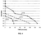
- PP534 type prismatic air metal-air cells were made using air electrodes containing one of two different catalysts, with vs. without gold plated current collectors. All cells had a negative electrode containing zinc powder as the active material and an aqueous potassium hydroxide electrolyte.
- the current collectors were made from 3 Ni 3.3-05P expanded metal; the current collectors in Lots A and C were not plated, and the current collectors in Lots B and D were plated with gold on essentially all of both the separator side and the port side of the expanded metal; and the current collectors were embedded into the separator sides of the catalytic layers.
- Air convection was provided to the test electrodes so the test results would not be limited by the amount of air available to the electrode during the test.
- the limiting current current at 1.05 V vs. zinc
- the average limiting current and the average maximum power are summarized in Table 1.
- Adhesion of the catalytic material to the gold plated current collector was observed to be improved when a graphite coating was added over the gold plating, and there was generally a desirable increase in limiting current and maximum power with a graphite coating. While adhesion of the catalytic material appeared to be best when both sides of the current collector was coated with graphite, surprisingly the limiting current and the maximum power were better when only the separator side of the current collector was coated with graphite. In general, limiting current and maximum power were better with the 4 Ni 5-060 P&L expanded metal than with the 3 Ni 3.3-05 expanded metal.
- Electrodes without a PTFE film layer were made from each current collector lot and tested for adhesion of the catalytic material to the current collector, using a pressure test in which a sample piece of electrode was mounting in a clamping device with a 0.635 cm (0.250 inch) opening on both sides of the sample and air pressure applied to the separator side of the electrode sample was gradually increased (at a rate of about 70.3 g/cm 2 (1 pound per square inch) per second), until there was an audible "pop" sound and the gauge pressure dropped to zero, indicating that the bond between the catalytic material and the current collector had broken.
- Table 2 These results show that adhesion was substantially improved when the current collector is coated with graphite. Adhesion was best when both sides of the current collector were coated with graphite, but even coating just one side provided a significant improvement over uncoated current collectors, both with and without gold plating.
- Electrodes were tested for alternating current (AC) impedance in half cells flooded with potassium hydroxide electrolyte solution vs. a zinc reference electrode, at open circuit potential, with a peak to peak alternating potential amplitude of 10 mV applied over a frequency range from 100 KHz to 0.1 Hz.
- the electrode impedance at 65 KHz is summarized in Table 2.
- Plating the current collector with gold generally resulted in lower electrode impedance, both with and without graphite coating.
- Gold plating and graphite coating of the current collector each resulted in a higher limiting current.
- the improvement was not as great as with an uncoated, gold plated current collector.
- the best results were achieved with a gold plated current collector coated with graphite on only the separator side, so that a portion of the gold plating was in contact with the catalytic material.
- Electrodes from each lot were tested in half cells flooded with aqueous potassium hydroxide electrolyte vs. a zinc reference electrode as described in Example 2.
- the results arc summarized in Table 2. The results are similar to those for electrode impedance.
- PP534 type prismatic zinc-air cells were made using electrodes from each lot. Negative electrodes containing zinc powder and the electrolyte was an aqueous potassium hydroxide solution.
- the limiting current of cells from each lot was determined using a polarization curve in the same manner as described above for the electrodes tested in half cells, except that air convection was not provided to the cells.
- the results are summarized in Table 2.
- Gold plating on the current collector only provided a substantial improvement in the cell limiting current unless a graphite coating was also applied over at least a portion of the current collector, and the combination of gold plating and graphite coating provided better results than a graphite coating without gold plating. The best results were achieved with both gold plating in combination with graphite coating on only the separator side of the current collector.
- Electrodes from each lot were tested for limiting current by the same method described in Example 3. Electrodes from each lot were also assembled into cells, and the cells were tested for limiting current as described in Example 3. The results are summarized in Table 3.
Landscapes
- Chemical & Material Sciences (AREA)
- Chemical Kinetics & Catalysis (AREA)
- Electrochemistry (AREA)
- General Chemical & Material Sciences (AREA)
- Engineering & Computer Science (AREA)
- Manufacturing & Machinery (AREA)
- Composite Materials (AREA)
- Life Sciences & Earth Sciences (AREA)
- Sustainable Development (AREA)
- Sustainable Energy (AREA)
- Hybrid Cells (AREA)
- Inert Electrodes (AREA)
Applications Claiming Priority (2)
| Application Number | Priority Date | Filing Date | Title |
|---|---|---|---|
| US18228509P | 2009-05-29 | 2009-05-29 | |
| PCT/US2010/036271 WO2010138643A1 (en) | 2009-05-29 | 2010-05-27 | Current collector for catalytic electrode |
Publications (3)
| Publication Number | Publication Date |
|---|---|
| EP2436083A1 EP2436083A1 (en) | 2012-04-04 |
| EP2436083B1 EP2436083B1 (en) | 2013-04-03 |
| EP2436083B2 true EP2436083B2 (en) | 2016-08-10 |
Family
ID=42470805
Family Applications (1)
| Application Number | Title | Priority Date | Filing Date |
|---|---|---|---|
| EP10725556.4A Not-in-force EP2436083B2 (en) | 2009-05-29 | 2010-05-27 | Current collector for catalytic electrodes |
Country Status (6)
| Country | Link |
|---|---|
| US (1) | US8541135B2 (enExample) |
| EP (1) | EP2436083B2 (enExample) |
| JP (1) | JP2012528465A (enExample) |
| CN (1) | CN102449843A (enExample) |
| IL (1) | IL215977A0 (enExample) |
| WO (1) | WO2010138643A1 (enExample) |
Families Citing this family (22)
| Publication number | Priority date | Publication date | Assignee | Title |
|---|---|---|---|---|
| US20140066290A1 (en) * | 2011-04-27 | 2014-03-06 | Sumitomo Chemical Company, Limited | Cathode catalyst for air secondary battery and air secondary battery |
| KR101351902B1 (ko) * | 2011-06-02 | 2014-01-22 | 주식회사 엘지화학 | 이차전지용 음극 및 이를 구비하는 이차전지 |
| EP2768062B1 (en) | 2011-10-13 | 2016-05-18 | LG Chem, Ltd. | Cable-type secondary battery |
| CN103891026B (zh) | 2011-10-13 | 2016-06-29 | 株式会社Lg化学 | 线缆型二次电池 |
| EP2768057B1 (en) | 2011-10-13 | 2016-08-31 | LG Chem, Ltd. | Cable-type secondary battery |
| EP2768058B1 (en) | 2011-10-13 | 2016-05-18 | LG Chem, Ltd. | Cable-type secondary battery |
| CN103891027B (zh) | 2011-10-25 | 2016-10-26 | 株式会社Lg化学 | 线缆型二次电池 |
| AU2013328267B2 (en) * | 2012-10-09 | 2018-06-28 | Phinergy Ltd | Electrode assembly and method for its preparation |
| EP3486992B1 (en) | 2013-06-28 | 2020-09-23 | Positec Power Tools (Suzhou) Co., Ltd | Battery |
| RU2619266C1 (ru) * | 2013-09-13 | 2017-05-15 | ЭлДжи КЕМ, ЛТД. | Положительный электрод для литиево-воздушной батареи и способ его приготовления |
| US11069891B2 (en) * | 2014-09-26 | 2021-07-20 | Positec Power Tools (Suzhou) Co., Ltd. | Battery, battery pack and continuous power supply |
| KR102349963B1 (ko) * | 2015-04-30 | 2022-01-11 | 삼성전자주식회사 | 실시간 분석을 위한 인-시츄 코인 셀과 이를 포함하는 측정 시스템과 인-시츄 코인 셀의 제조방법 및 광을 이용한 그 측정방법 |
| CN106374115A (zh) * | 2016-10-19 | 2017-02-01 | 深圳市锐劲宝能源电子有限公司 | 多层复合氧催化电极及其制作方法 |
| BR112019008041A2 (pt) | 2016-10-21 | 2019-07-02 | Nantenergy Inc | elétrodo de combustível corrugado |
| CN106848190B (zh) * | 2017-02-14 | 2019-10-08 | 珠海光宇电池有限公司 | 负极极片、负极极片的制备方法及锂离子电池 |
| JP7032973B2 (ja) * | 2018-03-29 | 2022-03-09 | 太陽誘電株式会社 | 全固体電池およびその製造方法 |
| MA53343A (fr) | 2018-07-27 | 2022-03-23 | Form Energy Inc | Électrodes négatives pour cellules électrochimiques |
| CN114072957A (zh) * | 2019-06-28 | 2022-02-18 | 福恩能源公司 | 低成本空气电极 |
| US12278381B2 (en) * | 2019-10-25 | 2025-04-15 | Sharp Kabushiki Kaisha | Laminate battery |
| CN113929188A (zh) * | 2020-06-29 | 2022-01-14 | 佛山市顺德区美的饮水机制造有限公司 | 电极结构、净化结构和电极制备方法 |
| KR20240141800A (ko) | 2022-01-28 | 2024-09-27 | 폼 에너지 인코퍼레이티드 | 양면 밀봉형 기체 확산 전극 |
| CN117002710A (zh) * | 2022-04-29 | 2023-11-07 | 哈尔滨工业大学(深圳) | 浮潜系统的浮潜控制方法及铝空气电池的浮潜应用 |
Family Cites Families (28)
| Publication number | Priority date | Publication date | Assignee | Title |
|---|---|---|---|---|
| US4248682A (en) | 1979-09-27 | 1981-02-03 | Prototech Company | Carbon-cloth-based electrocatalytic gas diffusion electrodes, assembly and electrochemical cells comprising the same |
| US4865925A (en) | 1987-12-14 | 1989-09-12 | Hughes Aircraft Company | Gas permeable electrode for electrochemical system |
| US5242565A (en) | 1989-07-10 | 1993-09-07 | August Winsel | Device for electrochemical generation of gases for the transportation of fluids and similar mediums |
| CA2046148C (en) | 1990-08-14 | 1997-01-07 | Dale R. Getz | Alkaline cells that are substantially free of mercury |
| US5312476A (en) | 1991-02-19 | 1994-05-17 | Matsushita Electric Industrial Co., Ltd. | Zinc alloy powder for alkaline cell and method for production of the same |
| US5308711A (en) | 1993-02-09 | 1994-05-03 | Rayovac Corporation | Metal-air cathode and cell having catalytically active manganese compounds of valence state +2 |
| JPH08264186A (ja) * | 1995-03-28 | 1996-10-11 | Matsushita Electric Ind Co Ltd | 円筒形空気亜鉛電池 |
| US5567538A (en) | 1995-05-05 | 1996-10-22 | Rayovac Corporation | Metal-air cell having thin-walled anode and cathode cans |
| US5707499A (en) | 1995-10-06 | 1998-01-13 | Ceramatec, Inc. | Storage-stable, fluid dispensing device using a hydrogen gas generator |
| US6060196A (en) | 1995-10-06 | 2000-05-09 | Ceramtec, Inc. | Storage-stable zinc anode based electrochemical cell |
| US6120940A (en) | 1996-10-30 | 2000-09-19 | The Johns Hopkins University | Electrochemical storage cell containing at least one electrode formulated from a phenylene-thienyl based polymer |
| US6436571B1 (en) | 1998-03-06 | 2002-08-20 | Rayovac Corporation | Bottom seals in air depolarized electrochemical cells |
| AU1831600A (en) | 1998-12-15 | 2000-07-03 | Electric Fuel Limited | An air electrode providing high current density for metal-air batteries |
| WO2000036686A1 (en) | 1998-12-15 | 2000-06-22 | Electric Fuel Limited | Corrosion resistant high performance electrochemical cell |
| US6602629B1 (en) | 2000-05-24 | 2003-08-05 | Eveready Battery Company, Inc. | Zero mercury air cell |
| US6403517B1 (en) | 2000-07-24 | 2002-06-11 | Microcell Corporation | System and process for manufacturing microcell electrochemical devices and assemblies |
| JP2002151086A (ja) * | 2000-09-04 | 2002-05-24 | Katayama Tokushu Kogyo Kk | 空気電池用正極基材、該正極基材の製造方法、空気電池用正極、および空気電池 |
| US20020132158A1 (en) | 2001-01-16 | 2002-09-19 | Jonathan Sassen | Air electrode providing high current density for metal-air batteries |
| JP4768134B2 (ja) * | 2001-01-19 | 2011-09-07 | 日立プラズマディスプレイ株式会社 | プラズマディスプレイ装置の駆動方法 |
| JP4963147B2 (ja) | 2001-09-17 | 2012-06-27 | 株式会社豊田中央研究所 | 燃料電池用電極触媒体およびその製造方法 |
| JP2003308849A (ja) | 2002-04-12 | 2003-10-31 | Tanaka Kikinzoku Kogyo Kk | 高分子固体電解質形燃料電池の燃料極用触媒 |
| US6933077B2 (en) | 2002-12-27 | 2005-08-23 | Avestor Limited Partnership | Current collector for polymer electrochemical cells and electrochemical generators thereof |
| US7001689B2 (en) | 2003-04-02 | 2006-02-21 | The Gillette Company | Zinc/air cell |
| JP2005019146A (ja) * | 2003-06-25 | 2005-01-20 | Toshiba Battery Co Ltd | 空気電池 |
| US7776468B2 (en) | 2004-03-18 | 2010-08-17 | The Gillette Company | Wafer alkaline cell |
| WO2006085691A1 (en) * | 2005-02-10 | 2006-08-17 | Showa Denko K.K | Secondary-battery cutrrent collector, secondary-battery cathode, secondary-battery anode, secondary battery and production method thereof |
| KR101528941B1 (ko) * | 2006-12-27 | 2015-06-15 | 에버레디 배터리 컴퍼니, 인크. | 촉매 전극을 갖는 전기화학 전지 및 전극과 전지 제조 방법 |
| US7976976B2 (en) * | 2007-02-07 | 2011-07-12 | Rosecreek Technologies Inc. | Composite current collector |
-
2010
- 2010-05-27 WO PCT/US2010/036271 patent/WO2010138643A1/en not_active Ceased
- 2010-05-27 JP JP2012513230A patent/JP2012528465A/ja active Pending
- 2010-05-27 CN CN2010800238467A patent/CN102449843A/zh active Pending
- 2010-05-27 EP EP10725556.4A patent/EP2436083B2/en not_active Not-in-force
- 2010-06-01 US US12/791,042 patent/US8541135B2/en active Active
-
2011
- 2011-10-27 IL IL215977A patent/IL215977A0/en unknown
Also Published As
| Publication number | Publication date |
|---|---|
| US20100304274A1 (en) | 2010-12-02 |
| CN102449843A (zh) | 2012-05-09 |
| EP2436083A1 (en) | 2012-04-04 |
| IL215977A0 (en) | 2012-01-31 |
| WO2010138643A1 (en) | 2010-12-02 |
| JP2012528465A (ja) | 2012-11-12 |
| US8541135B2 (en) | 2013-09-24 |
| EP2436083B1 (en) | 2013-04-03 |
Similar Documents
| Publication | Publication Date | Title |
|---|---|---|
| EP2436083B2 (en) | Current collector for catalytic electrodes | |
| CN101573815B (zh) | 制备催化电极的方法和采用该电极的电化学电池 | |
| EP1878072B1 (en) | Nickel zinc battery design | |
| US6248476B1 (en) | Metal air cathode and electrochemical cells made therewith | |
| JP2009545852A (ja) | 電気化学セルのための非導電性コア及び表面金属化を有するネイル型集電体 | |
| JP5468136B2 (ja) | 燃料電池 | |
| KR20180037174A (ko) | 금속 다공체, 연료 전지 및, 금속 다공체의 제조 방법 | |
| CA2533138C (en) | Fuel cell | |
| JPH07282860A (ja) | アルカリ二次電池及び触媒性電極体の製造法 | |
| CN101322282A (zh) | 锌/空气电池 | |
| WO1999035701A1 (en) | Zinc based electrochemical cell | |
| US9966609B2 (en) | Gas diffusion electrode and process for making same | |
| US12199291B2 (en) | Electrochemical cell with bilayer electrocatalyst structure | |
| JPH08203538A (ja) | ガス拡散型空気極 | |
| HK1137854B (en) | Process for making an electrochemical cell with a catalytic electrode | |
| HK1135800B (en) | Process for making a catalytic electrode |
Legal Events
| Date | Code | Title | Description |
|---|---|---|---|
| PUAI | Public reference made under article 153(3) epc to a published international application that has entered the european phase |
Free format text: ORIGINAL CODE: 0009012 |
|
| 17P | Request for examination filed |
Effective date: 20111028 |
|
| AK | Designated contracting states |
Kind code of ref document: A1 Designated state(s): AL AT BE BG CH CY CZ DE DK EE ES FI FR GB GR HR HU IE IS IT LI LT LU LV MC MK MT NL NO PL PT RO SE SI SK SM TR |
|
| DAX | Request for extension of the european patent (deleted) | ||
| REG | Reference to a national code |
Ref country code: HK Ref legal event code: DE Ref document number: 1165619 Country of ref document: HK |
|
| GRAP | Despatch of communication of intention to grant a patent |
Free format text: ORIGINAL CODE: EPIDOSNIGR1 |
|
| GRAS | Grant fee paid |
Free format text: ORIGINAL CODE: EPIDOSNIGR3 |
|
| GRAA | (expected) grant |
Free format text: ORIGINAL CODE: 0009210 |
|
| AK | Designated contracting states |
Kind code of ref document: B1 Designated state(s): AL AT BE BG CH CY CZ DE DK EE ES FI FR GB GR HR HU IE IS IT LI LT LU LV MC MK MT NL NO PL PT RO SE SI SK SM TR |
|
| REG | Reference to a national code |
Ref country code: GB Ref legal event code: FG4D |
|
| REG | Reference to a national code |
Ref country code: CH Ref legal event code: EP Ref country code: AT Ref legal event code: REF Ref document number: 605220 Country of ref document: AT Kind code of ref document: T Effective date: 20130415 |
|
| REG | Reference to a national code |
Ref country code: IE Ref legal event code: FG4D |
|
| REG | Reference to a national code |
Ref country code: CH Ref legal event code: NV Representative=s name: BOHEST AG, CH |
|
| REG | Reference to a national code |
Ref country code: DE Ref legal event code: R096 Ref document number: 602010006083 Country of ref document: DE Effective date: 20130606 |
|
| REG | Reference to a national code |
Ref country code: AT Ref legal event code: MK05 Ref document number: 605220 Country of ref document: AT Kind code of ref document: T Effective date: 20130403 |
|
| PG25 | Lapsed in a contracting state [announced via postgrant information from national office to epo] |
Ref country code: SI Free format text: LAPSE BECAUSE OF FAILURE TO SUBMIT A TRANSLATION OF THE DESCRIPTION OR TO PAY THE FEE WITHIN THE PRESCRIBED TIME-LIMIT Effective date: 20130403 |
|
| REG | Reference to a national code |
Ref country code: NL Ref legal event code: VDEP Effective date: 20130403 |
|
| REG | Reference to a national code |
Ref country code: LT Ref legal event code: MG4D |
|
| PG25 | Lapsed in a contracting state [announced via postgrant information from national office to epo] |
Ref country code: ES Free format text: LAPSE BECAUSE OF FAILURE TO SUBMIT A TRANSLATION OF THE DESCRIPTION OR TO PAY THE FEE WITHIN THE PRESCRIBED TIME-LIMIT Effective date: 20130714 Ref country code: PT Free format text: LAPSE BECAUSE OF FAILURE TO SUBMIT A TRANSLATION OF THE DESCRIPTION OR TO PAY THE FEE WITHIN THE PRESCRIBED TIME-LIMIT Effective date: 20130805 Ref country code: AT Free format text: LAPSE BECAUSE OF FAILURE TO SUBMIT A TRANSLATION OF THE DESCRIPTION OR TO PAY THE FEE WITHIN THE PRESCRIBED TIME-LIMIT Effective date: 20130403 Ref country code: GR Free format text: LAPSE BECAUSE OF FAILURE TO SUBMIT A TRANSLATION OF THE DESCRIPTION OR TO PAY THE FEE WITHIN THE PRESCRIBED TIME-LIMIT Effective date: 20130704 Ref country code: NL Free format text: LAPSE BECAUSE OF FAILURE TO SUBMIT A TRANSLATION OF THE DESCRIPTION OR TO PAY THE FEE WITHIN THE PRESCRIBED TIME-LIMIT Effective date: 20130403 Ref country code: SE Free format text: LAPSE BECAUSE OF FAILURE TO SUBMIT A TRANSLATION OF THE DESCRIPTION OR TO PAY THE FEE WITHIN THE PRESCRIBED TIME-LIMIT Effective date: 20130403 Ref country code: FI Free format text: LAPSE BECAUSE OF FAILURE TO SUBMIT A TRANSLATION OF THE DESCRIPTION OR TO PAY THE FEE WITHIN THE PRESCRIBED TIME-LIMIT Effective date: 20130403 Ref country code: IS Free format text: LAPSE BECAUSE OF FAILURE TO SUBMIT A TRANSLATION OF THE DESCRIPTION OR TO PAY THE FEE WITHIN THE PRESCRIBED TIME-LIMIT Effective date: 20130803 Ref country code: NO Free format text: LAPSE BECAUSE OF FAILURE TO SUBMIT A TRANSLATION OF THE DESCRIPTION OR TO PAY THE FEE WITHIN THE PRESCRIBED TIME-LIMIT Effective date: 20130703 Ref country code: LT Free format text: LAPSE BECAUSE OF FAILURE TO SUBMIT A TRANSLATION OF THE DESCRIPTION OR TO PAY THE FEE WITHIN THE PRESCRIBED TIME-LIMIT Effective date: 20130403 |
|
| PG25 | Lapsed in a contracting state [announced via postgrant information from national office to epo] |
Ref country code: CY Free format text: LAPSE BECAUSE OF FAILURE TO SUBMIT A TRANSLATION OF THE DESCRIPTION OR TO PAY THE FEE WITHIN THE PRESCRIBED TIME-LIMIT Effective date: 20130403 Ref country code: LV Free format text: LAPSE BECAUSE OF FAILURE TO SUBMIT A TRANSLATION OF THE DESCRIPTION OR TO PAY THE FEE WITHIN THE PRESCRIBED TIME-LIMIT Effective date: 20130403 Ref country code: HR Free format text: LAPSE BECAUSE OF FAILURE TO SUBMIT A TRANSLATION OF THE DESCRIPTION OR TO PAY THE FEE WITHIN THE PRESCRIBED TIME-LIMIT Effective date: 20130403 Ref country code: PL Free format text: LAPSE BECAUSE OF FAILURE TO SUBMIT A TRANSLATION OF THE DESCRIPTION OR TO PAY THE FEE WITHIN THE PRESCRIBED TIME-LIMIT Effective date: 20130403 Ref country code: BG Free format text: LAPSE BECAUSE OF FAILURE TO SUBMIT A TRANSLATION OF THE DESCRIPTION OR TO PAY THE FEE WITHIN THE PRESCRIBED TIME-LIMIT Effective date: 20130703 |
|
| PLBI | Opposition filed |
Free format text: ORIGINAL CODE: 0009260 |
|
| PG25 | Lapsed in a contracting state [announced via postgrant information from national office to epo] |
Ref country code: MC Free format text: LAPSE BECAUSE OF FAILURE TO SUBMIT A TRANSLATION OF THE DESCRIPTION OR TO PAY THE FEE WITHIN THE PRESCRIBED TIME-LIMIT Effective date: 20130403 Ref country code: DK Free format text: LAPSE BECAUSE OF FAILURE TO SUBMIT A TRANSLATION OF THE DESCRIPTION OR TO PAY THE FEE WITHIN THE PRESCRIBED TIME-LIMIT Effective date: 20130403 Ref country code: SK Free format text: LAPSE BECAUSE OF FAILURE TO SUBMIT A TRANSLATION OF THE DESCRIPTION OR TO PAY THE FEE WITHIN THE PRESCRIBED TIME-LIMIT Effective date: 20130403 Ref country code: CZ Free format text: LAPSE BECAUSE OF FAILURE TO SUBMIT A TRANSLATION OF THE DESCRIPTION OR TO PAY THE FEE WITHIN THE PRESCRIBED TIME-LIMIT Effective date: 20130403 Ref country code: EE Free format text: LAPSE BECAUSE OF FAILURE TO SUBMIT A TRANSLATION OF THE DESCRIPTION OR TO PAY THE FEE WITHIN THE PRESCRIBED TIME-LIMIT Effective date: 20130403 |
|
| 26 | Opposition filed |
Opponent name: VARTA MICROBATTERY GMBH Effective date: 20140103 |
|
| PLAX | Notice of opposition and request to file observation + time limit sent |
Free format text: ORIGINAL CODE: EPIDOSNOBS2 |
|
| REG | Reference to a national code |
Ref country code: IE Ref legal event code: MM4A |
|
| PG25 | Lapsed in a contracting state [announced via postgrant information from national office to epo] |
Ref country code: RO Free format text: LAPSE BECAUSE OF FAILURE TO SUBMIT A TRANSLATION OF THE DESCRIPTION OR TO PAY THE FEE WITHIN THE PRESCRIBED TIME-LIMIT Effective date: 20130403 Ref country code: IT Free format text: LAPSE BECAUSE OF FAILURE TO SUBMIT A TRANSLATION OF THE DESCRIPTION OR TO PAY THE FEE WITHIN THE PRESCRIBED TIME-LIMIT Effective date: 20130403 |
|
| REG | Reference to a national code |
Ref country code: FR Ref legal event code: ST Effective date: 20140131 |
|
| REG | Reference to a national code |
Ref country code: DE Ref legal event code: R026 Ref document number: 602010006083 Country of ref document: DE Effective date: 20140103 |
|
| PG25 | Lapsed in a contracting state [announced via postgrant information from national office to epo] |
Ref country code: IE Free format text: LAPSE BECAUSE OF NON-PAYMENT OF DUE FEES Effective date: 20130527 |
|
| PG25 | Lapsed in a contracting state [announced via postgrant information from national office to epo] |
Ref country code: FR Free format text: LAPSE BECAUSE OF NON-PAYMENT OF DUE FEES Effective date: 20130603 |
|
| PLAF | Information modified related to communication of a notice of opposition and request to file observations + time limit |
Free format text: ORIGINAL CODE: EPIDOSCOBS2 |
|
| PGFP | Annual fee paid to national office [announced via postgrant information from national office to epo] |
Ref country code: GB Payment date: 20140527 Year of fee payment: 5 |
|
| REG | Reference to a national code |
Ref country code: CH Ref legal event code: PCAR Free format text: NEW ADDRESS: HOLBEINSTRASSE 36-38, 4051 BASEL (CH) |
|
| PLBB | Reply of patent proprietor to notice(s) of opposition received |
Free format text: ORIGINAL CODE: EPIDOSNOBS3 |
|
| PGFP | Annual fee paid to national office [announced via postgrant information from national office to epo] |
Ref country code: CH Payment date: 20140527 Year of fee payment: 5 |
|
| PGFP | Annual fee paid to national office [announced via postgrant information from national office to epo] |
Ref country code: BE Payment date: 20140530 Year of fee payment: 5 |
|
| PG25 | Lapsed in a contracting state [announced via postgrant information from national office to epo] |
Ref country code: MT Free format text: LAPSE BECAUSE OF FAILURE TO SUBMIT A TRANSLATION OF THE DESCRIPTION OR TO PAY THE FEE WITHIN THE PRESCRIBED TIME-LIMIT Effective date: 20130403 |
|
| PG25 | Lapsed in a contracting state [announced via postgrant information from national office to epo] |
Ref country code: SM Free format text: LAPSE BECAUSE OF FAILURE TO SUBMIT A TRANSLATION OF THE DESCRIPTION OR TO PAY THE FEE WITHIN THE PRESCRIBED TIME-LIMIT Effective date: 20130403 |
|
| PG25 | Lapsed in a contracting state [announced via postgrant information from national office to epo] |
Ref country code: TR Free format text: LAPSE BECAUSE OF FAILURE TO SUBMIT A TRANSLATION OF THE DESCRIPTION OR TO PAY THE FEE WITHIN THE PRESCRIBED TIME-LIMIT Effective date: 20130403 |
|
| PG25 | Lapsed in a contracting state [announced via postgrant information from national office to epo] |
Ref country code: LU Free format text: LAPSE BECAUSE OF NON-PAYMENT OF DUE FEES Effective date: 20130527 Ref country code: MK Free format text: LAPSE BECAUSE OF FAILURE TO SUBMIT A TRANSLATION OF THE DESCRIPTION OR TO PAY THE FEE WITHIN THE PRESCRIBED TIME-LIMIT Effective date: 20130403 Ref country code: HU Free format text: LAPSE BECAUSE OF FAILURE TO SUBMIT A TRANSLATION OF THE DESCRIPTION OR TO PAY THE FEE WITHIN THE PRESCRIBED TIME-LIMIT; INVALID AB INITIO Effective date: 20100527 |
|
| REG | Reference to a national code |
Ref country code: DE Ref legal event code: R082 Ref document number: 602010006083 Country of ref document: DE Representative=s name: VON KREISLER SELTING WERNER - PARTNERSCHAFT VO, DE Ref country code: DE Ref legal event code: R081 Ref document number: 602010006083 Country of ref document: DE Owner name: ENERGIZER BRANDS, LLC, ST. LOUIS, US Free format text: FORMER OWNER: EVEREADY BATTERY CO., INC., ST. LOUIS, MO., US Ref country code: DE Ref legal event code: R082 Ref document number: 602010006083 Country of ref document: DE Representative=s name: DOMPATENT VON KREISLER SELTING WERNER - PARTNE, DE |
|
| RAP2 | Party data changed (patent owner data changed or rights of a patent transferred) |
Owner name: ENERGIZER BRANDS, LLC |
|
| PLBP | Opposition withdrawn |
Free format text: ORIGINAL CODE: 0009264 |
|
| REG | Reference to a national code |
Ref country code: CH Ref legal event code: PL |
|
| GBPC | Gb: european patent ceased through non-payment of renewal fee |
Effective date: 20150527 |
|
| PG25 | Lapsed in a contracting state [announced via postgrant information from national office to epo] |
Ref country code: CH Free format text: LAPSE BECAUSE OF NON-PAYMENT OF DUE FEES Effective date: 20150531 Ref country code: LI Free format text: LAPSE BECAUSE OF NON-PAYMENT OF DUE FEES Effective date: 20150531 |
|
| PG25 | Lapsed in a contracting state [announced via postgrant information from national office to epo] |
Ref country code: GB Free format text: LAPSE BECAUSE OF NON-PAYMENT OF DUE FEES Effective date: 20150527 |
|
| PUAH | Patent maintained in amended form |
Free format text: ORIGINAL CODE: 0009272 |
|
| STAA | Information on the status of an ep patent application or granted ep patent |
Free format text: STATUS: PATENT MAINTAINED AS AMENDED |
|
| PGFP | Annual fee paid to national office [announced via postgrant information from national office to epo] |
Ref country code: DE Payment date: 20160527 Year of fee payment: 7 |
|
| 27A | Patent maintained in amended form |
Effective date: 20160810 |
|
| AK | Designated contracting states |
Kind code of ref document: B2 Designated state(s): AL AT BE BG CH CY CZ DE DK EE ES FI FR GB GR HR HU IE IS IT LI LT LU LV MC MK MT NL NO PL PT RO SE SI SK SM TR |
|
| REG | Reference to a national code |
Ref country code: DE Ref legal event code: R102 Ref document number: 602010006083 Country of ref document: DE |
|
| REG | Reference to a national code |
Ref country code: GB Ref legal event code: 732E Free format text: REGISTERED BETWEEN 20161013 AND 20161019 |
|
| PG25 | Lapsed in a contracting state [announced via postgrant information from national office to epo] |
Ref country code: BE Free format text: LAPSE BECAUSE OF NON-PAYMENT OF DUE FEES Effective date: 20150531 |
|
| REG | Reference to a national code |
Ref country code: DE Ref legal event code: R119 Ref document number: 602010006083 Country of ref document: DE |
|
| PG25 | Lapsed in a contracting state [announced via postgrant information from national office to epo] |
Ref country code: DE Free format text: LAPSE BECAUSE OF NON-PAYMENT OF DUE FEES Effective date: 20171201 |
|
| PG25 | Lapsed in a contracting state [announced via postgrant information from national office to epo] |
Ref country code: AL Free format text: LAPSE BECAUSE OF FAILURE TO SUBMIT A TRANSLATION OF THE DESCRIPTION OR TO PAY THE FEE WITHIN THE PRESCRIBED TIME-LIMIT Effective date: 20130403 |
|
| REG | Reference to a national code |
Ref country code: HK Ref legal event code: WD Ref document number: 1165619 Country of ref document: HK |