EP2435889B1 - Anzeige für ein informationsspeichermodul - Google Patents
Anzeige für ein informationsspeichermodul Download PDFInfo
- Publication number
- EP2435889B1 EP2435889B1 EP10780918.8A EP10780918A EP2435889B1 EP 2435889 B1 EP2435889 B1 EP 2435889B1 EP 10780918 A EP10780918 A EP 10780918A EP 2435889 B1 EP2435889 B1 EP 2435889B1
- Authority
- EP
- European Patent Office
- Prior art keywords
- media module
- display unit
- optical signal
- management information
- optical
- Prior art date
- Legal status (The legal status is an assumption and is not a legal conclusion. Google has not performed a legal analysis and makes no representation as to the accuracy of the status listed.)
- Not-in-force
Links
Images




Classifications
-
- G—PHYSICS
- G11—INFORMATION STORAGE
- G11B—INFORMATION STORAGE BASED ON RELATIVE MOVEMENT BETWEEN RECORD CARRIER AND TRANSDUCER
- G11B33/00—Constructional parts, details or accessories not provided for in the other groups of this subclass
- G11B33/10—Indicating arrangements; Warning arrangements
-
- G—PHYSICS
- G06—COMPUTING OR CALCULATING; COUNTING
- G06F—ELECTRIC DIGITAL DATA PROCESSING
- G06F1/00—Details not covered by groups G06F3/00 - G06F13/00 and G06F21/00
- G06F1/16—Constructional details or arrangements
- G06F1/1613—Constructional details or arrangements for portable computers
- G06F1/1632—External expansion units, e.g. docking stations
Definitions
- This invention pertains to information storage, and particularly to information storage devices or units which incorporate or include media modules such as cartridges or cassettes of information storage media.
- RAM random access memory
- RAM read only memory
- Many computer systems also have access to additional memory in the form of electronic (e.g. magnetic) media which is stored in a removable unit or media module such as cassette or cartridge.
- the removable media module can be inserted into a slot or port or rack of the computer frame in order to facilitate input/output operations of data (e.g., recording and reproduction of data in the form of signals written to or read from the storage media).
- RDX®-type cartridge which comprises a disk drive mounted in a sealed exterior cartridge.
- the disk drive is a laptop-style 2.5-inch disk drive, which has built-in accelerometers, head ramp unloading, and other features that makes it more tolerant of shock and vibration than their 3.5-inch counterparts.
- the cartridge can be inserted into an external USB or internal SATA dock that locks the cartridge in place under software control so the user cannot remove a cartridge undergoing a recording operation.
- the RDX®-type cartridge has a SATA interface connector that provides the power and data communication interface between the hard disk drive and a docking station.
- the RDX®-type cartridge has a plastic cartridge shell and internal shock isolation material around the hard disk drive to provide a shock-mounting system.
- the cartridge has no other electronics besides that in the hard disk drive.
- a Lexmark Jump drive a USB flash memory stick has a capacity bar graph display which obtains the information to be displayed through the native host USB interface in the product, but not through a separate optical link.
- a primitive way of identifying a storage media module is to provide a legible label to a prominent surface of the media module. That is, for identification purposes existing prior art modules typically only have a paper bar graph label or serial number on the module.
- GB 2 452 611 A discloses a docking station which communicates preferences from an accessory to a media player.
- the technology disclosed herein concerns a computer memory system which comprises a media module; a host computer configured to accommodate the media module in removable fashion; and a display unit.
- the media module is configured to store electronic data.
- the host computer comprises a docking station configured to accommodate the media module; an interface through which electronic signals representing the electronic data are transmitted between the host computer and the media module; an optical indicator; and a host processor.
- the host processor is configured to control a read/write operation over the interface between the host computer and the media module and to activate the optical indicator. When activated, the optical indicator provides (not over the first interface) a first optical signal depicting transmission of electronic signals over the interface in the read/write operation.
- the host processor is further configured to drive the optical indicator whereby the optical indicator provides a second optical signal modulated to represent media module management information.
- the display unit of the system comprises an optical receiver; an output display device; and a display unit processor.
- the optical receiver is configured to receive the second optical signal.
- the output display device configured to provide a visible representation of the media module management information.
- the display unit processor configured to interpret the second optical signal and to display the media module management information derived there from on the output display device.
- the display unit further comprises a memory
- the display unit processor is further configured to store the media module management information derived from the second optical signal in the memory and (upon request) to drive the output display device with the media module management information obtained from the memory.
- An example embodiment further comprises light transmission means (e.g., a light pipe) for transmitting the second optical signal from the optical indicator to the optical receiver.
- light transmission means e.g., a light pipe
- the optical indicator comprises a light emitting diode (LED).
- the display unit is connected to the media module.
- the display unit attaches as a separate unit to the media module.
- the display unit is integrally incorporated into the media module.
- the display unit is connected to the host computer.
- the display unit is situated in a second docking station of the host computer.
- the display unit comprises an independent power supply. In an alternate example embodiment the display unit is configured to obtain power supply from the host computer.
- the media module management information comprises at least one of (1) remaining capacity of the media module; (2) name of the media module; (3) a job name; (4) a date of access of the media module; (5) operational status of the media module; (6) total capacity of the media module; and (7) one or more barcodes.
- the barcode(s) can represent one or more of (1) - (6).
- the media module comprises a media module frame which carries a disk memory device, such as a disk drive or a solid state disk.
- the technology disclosed herein concerns a media module.
- the media module comprises a media module frame; a memory device configured to store electronic data; and a display unit.
- the display unit is connected to the media module and comprises an optical receiver; an output display device; and a display unit processor.
- the optical receiver is configured to receive from a host computer an optical signal modulated to represent media module management information.
- the output display device is configured to provide a visible representation of the media module management information.
- the display unit processor is configured to interpret the optical signal and to display the media module management information derived there from on the output display device.
- the technology disclosed herein concerns a display unit for use with a media module of a type which stores electronic data.
- the display unit comprises an optical receiver; an output display device; and a display unit processor.
- the optical receiver is configured to receive from a host computer an optical signal modulated to represent media module management information.
- the output display device is configured to provide a visible representation of the media module management information.
- the display unit processor is configured to interpret the optical signal and to display the media module management information derived there from on the output display device.
- the display unit is connected to or connectable to the media module.
- the display unit is connectable to the host computer.
- the display unit comprises a frame which is insertable into a docking station of the host computer.
- a computer is generally understood to comprise one or more processors, and the terms computer and processor may be employed interchangeably herein.
- the functions may be provided by a single dedicated computer or processor, by a single shared computer or processor, or by a plurality of individual computers or processors, some of which may be shared or distributed. Such functions are to be understood as being computer-implemented and thus machine-implemented.
- processor or “controller” shall also be construed to refer to other hardware capable of performing such functions and/or executing software, and may include, without limitation, digital signal processor (DSP) hardware, reduced instruction set processor, hardware (e.g., digital or analog) circuitry, and (where appropriate) state machines capable of performing such functions.
- DSP digital signal processor
- reduced instruction set processor hardware (e.g., digital or analog) circuitry, and (where appropriate) state machines capable of performing such functions.
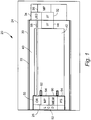
- Fig. 1 shows an example embodiment of a computer memory system 20 which comprises media module 22; host computer 24 configured to accommodate the media module 22 in removable fashion; and display unit 26.
- the media module 22 is configured to store electronic data, and can be any type of media module such as a cassette or cartridge, for example, which stores or accommodates an information storage medium wherein information is recordable and reproducible either electronically, magnetically, or optically.
- the host computer 24 comprises a docking station 30 configured to accommodate the media module 22; an interface/connector 32 through which electronic signals representing the electronic data are transmitted between host computer 24 and media module 22; optical indicator 34; and host processor 36.
- the host computer 24 can be any type of computer/processor-based or computer/processor-utilizing device, such as a desktop type computer or even a media storage drive that fits into or connects to a computer.
- the docking station 30 essentially takes the form of an internal cavity or bay provided within a frame or cabinet of the computer memory system 20.
- the docking station can be, for example, a particular slot in a host cabinet that accommodates plural adjacent slots, such as slots for disk drive units and the like.
- the docking station 30 is sized to accommodate internally the media module 22.
- Fig. 2 illustrates how the media module 22 of the first embodiment can be inserted into and removed from an example docking station of host computer 24.
- the host processor 36 executes coded instructions in the form of one or more computer programs to control a read/write operation over the interface between the host computer and the media module.
- the host processor 36 controls the transmission of electronic signals representing the electronic data as such electronic data is recorded on or reproduced from the media module 22.
- host processor 36 activates optical indicator 34 as so to provide a first optical signal depicting transmission of electronic signals over the interface in the read/write operation.
- the first optical signal can be the usual blinking of optical indicator 34 that occurs during a read or write operation to illustrate the occurrence of signal transmission between media module 22 and host computer 24.
- host processor 36 is configured to drive optical indicator 34 so that optical indicator 34 provides a second optical signal.
- the second optical signal is modulated or coded to represent media module management information.
- the media module management information comprises one or more of (1) remaining capacity of the media module; (2) name of the media module; (3) a job name; (4) a date of access of the media module; (5) operational status of the media module; (6) total capacity of the media module; and (7) one or more barcodes.
- the barcode(s) can represent one or more of (1) - (6).
- the media module 22 comprises media module frame 40.
- the media module frame 40 in turn internally accommodates or carries an information storage device or media, such as a disk memory device 42.
- the disk memory device 42 can be a disk drive or a solid state disk.
- media module 22 typically comprises a circuit board or the like upon which various components (e.g., electronic components) are positioned, including an interface/connector 44 which connects media module 22 to host computer 24.
- Display unit 26 is connected to media module 22 and comprises optical receiver 50; output display device 52; and display unit processor 54.
- the optical receiver 50 is configured to receive the second optical signal. Reception of the second optical signal by optical receiver 50 can occur by virtue of optical alignment of optical receiver 50 with optical indicator 34, or by conduction of the second optical signal from optical indicator 34 to optical receiver 50 through an optical transmission medium.
- an optical transmission medium can take the form of light pipe 58. A first end of light pipe 58 is positioned near or connected to optical indicator 34; a second end of light pipe 58 is positioned near or connected to optical receiver 50.
- the output display device 52 is configured to provide a visible representation of the media module management information.
- the 52 can take the form of a liquid crystal display, for example.
- the display unit processor 54 serves, e.g., to interpret the second optical signal and to display the media module management information derived there from on output display device 52.
- display unit 26 further optionally comprises memory 60.
- display unit processor 54 is further configured to store the media module management information derived from the second optical signal in memory 60 and (upon request) to drive the output display device 52 with the media module management information obtained from memory 60.
- memory 60 is a non-volatile memory.
- display unit 26 attaches as a separate unit to media module 22.
- display unit 26 can be attached to a face of media module 22 which, upon insertion of media module 22 into docking station 30, is oriented toward the mouth or opening of docking station 30, and thus is the trailing face of media module 22 as media module 22 is inserted into docking station 30.
- display unit 26 is provided with means for attaching a frame of display unit 26 to media module 22.
- the attaching means can take the form of one or more resilient clips 62 positioned to engage corresponding notches or recesses on a frame of media module 22. Clipping on the front of the media module in the manner of the example embodiment of Fig.
- Fig. 1 has the benefit in that the entire installed base of media modules can accept this product.
- the display unit 26 of the example embodiment of Fig. 1 is thus further illustrated in Fig. 3 (rear of the clip-on display unit) and Fig. 4 (front of the clip-on display unit).
- Fig. 3 particularly shows the display unit as comprising circuit board 70.
- the circuit board 70 can have mounted thereon the output display device 52 (a rear surface of which is shown in Fig. 3 ) and display unit processor 54.
- display unit 26 comprises an independent power supply 64 (see Fig. 1 and Fig. 3 ).
- the power supply 64 can take the form of a battery, for example.
- the light pipe 58 serves to direct both the first optical signal and the second optical signal both to optical receiver 50 (see Fig. 4 ) and to window 74 (see Fig. 4 ).
- Fig. 1 thus shows an example embodiment wherein display unit is attached to media module 22 as a separate and independent unit.
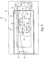
- display unit 26' is connected to the media module by being integrally incorporated into media module 22'.
- some or all of the constituent components of display unit 26' can reside on a circuit board 70' (e.g., mother board or the like) that resides in or is positioned on media module 22'.
- the circuit board 70' is positioned on a bottom side of media module 22', for which reason circuit board 70' and elements mounted thereon are illustrated by broken lines in Fig. 5 .
- Fig. 5 shows optical receiver 50, display unit processor 54, and memory 60 (as well as interface/connector 44) residing on circuit board 70.
- the processor which serves as display unit processor 54 can also perform other functions for media module 22'.
- light pipe 58 can have a light pipe branch 72 which directs at least a portion of the second optical signal emanating from optical indicator 34 to optical receiver 50.
- a primary segment of light pipe 58 has a first end connected to optical indicator 34 and a second end exposed or connected to a window 74 formed on a face of media module 22'.
- the light pipe 58 thus serves to direct both the first optical signal and the second optical signal both to optical receiver 50 and to window 74.
- light pipe 58 may work sufficiently to route some light to the optical receiver 50
- a small Y branch off light pipe 58 such as light pipe branch 72 can be provided to route the light to optical receiver 50.
- the light pipe branch 72 also reduces the chance of unwanted interference from a strong light in the environment coming in the reverse direction.
- circuit board 70' can obtain power supply from the host computer, e.g., be connected to receive power from host power supply 76 through interface/connector 44 as indicated by power lead 78. It will be appreciated that in other example embodiments the power to circuit board 70' can be obtained from the host computer via another or second connected, e.g., a smaller power connector which connects the circuit board 70 ultimately to a power source of the host computer.
- Fig. 2 also illustrates how the media module 22' of the second embodiment can be inserted into and removed from host computer 24.
- Fig. 2 also shows an example format of a front bezel or panel of display unit 26, including positioning of output display device 52 as well as an optional start/stop scrolling button or switch 80.
- the display unit processor 54 fetches the media module management information from memory 60 and prompts display of some or all of the elements of media module management information on output display device 52.
- the media module comprises a media module frame 40, and that media module frame 40 in turn internally accommodates or carries an information storage device or media, such as a disk memory device 42.
- Fig. 6 shows, in the example context of the second embodiment of Fig. 5 , a modified media module frame or shell with the drive and top cover removed.
- Fig. 6 particularly illustrates output display device 52, media module electronics board 70'; battery 64'; and light pipe 58.
- the electronic components residing on media module electronics board 70' are not shown in Fig. 6 , but are depicted in Fig. 5 .
- the display unit 26-7 is connected to a surface an exterior of a cabinet or frame for the host computer 24.
- Fig. 7 particularly shows the display unit 26-7 as being mounted on a front surface or front panel of host computer 24, and adjacent (e.g., above) the docking station 30 which accommodates the media module 22-7.
- the display unit 26-7 of Fig. 7 can be essentially modular or self-contained in similar manner as shown in Fig. 3 and Fig. 4 , but attaches to the host computer 24 instead of to the media module 22-7.
- the display unit 26-7 can be attached to host computer 24 by any suitable means, such as screws or fasteners which penetrate the frame or cabinet of host computer 24.
- display unit 26-7 can be attached or secured to host computer 24 by other means such as Velcro type fasteners, double-sided adhesive(s), epoxy adhesive(s), magnets, or the like.
- the display unit 26-7 connects to a light pipe 58-7 for communication and reception of the second optical signal.
- a distal end of the light pipe 58 serving and connected to the display unit 26-7 preferably extends through a hole or aperture formed in the frame or cabinet of the host computer 24.
- the display unit 26-7 can have its own battery, or be connected to a power source 76 of the host computer 24. If connected to the host computer power source, a power connector extends through a hole or aperture in a cabinet wall or frame of the host computer to connect to the display unit 26-7.
- Fig. 8 illustrates another example embodiment wherein display unit 26-G is mounted near the media module, e.g., connected to or mounted on the host computer.
- Fig. 8 shows display unit 26-G as being situated in docking station 30-G which takes the form of a slot or rack of a accessory (e.g., peripheral) mounting area of the host computer.
- the docking station 30-G happens to have four bays or slots for reception of peripheral devices or computer accessories.
- Fig. 8 shows that the media module 22 is situated in a second-7rom-the-top bay and has its lower surface riding on sleds of the second-7rom-the-top bay.
- the display unit 26-G that is associated with media module 22 is situated in a top-most bay of docking station 30, and thus rides on the sleds of the uppermost bay.
- the media module 22 may occupy a preponderance of its bay
- the display unit 26-G need not occupy its entire bay.
- the display unit 26-G can be essentially similar (e.g., in size and configuration) to the display unit 26 of Fig. 2 and Fig. 3 , but with side panels or flanges that are sized and/or configured to engage the sled-grooved inner wall of docking station 30 in its bay in such a manner that display unit 26-G is retained within the bay.
- Fig. 8 also shows that the display unit 26-G is positioned so that its optical receiver connected to a distal end of light pipe 58-G.
- the light pipe 58-G can connect back to the board of the host computer 24-G which carries the optical indicator 34, or be spliced into or coupled to another light pipe (e.g., a light pipe serving the media module) that connects to the optical indicator 34.
- the display unit 26-G can have its own battery, or be connected to a power source 76 of the host computer 24-G.
- display modules which are connected to the host computer, such as display unit 26-7 and display unit 26-G, are particularly suited for a media module which essentially remains connected to the host computer for a long period of time, e.g., for the useful life of the media module or until system upgrade.
- the media modules may be interchanged or swapped more frequently, in which case it is more beneficial to have the display unit connected to the removable media module so that the media module management information can be read or displayed while the media module is remote from the host computer.
- Fig. 9 schematically depicts portions of logic routines 82 executed by host processor 36.
- the various routines executed by host processor 36 are indicator pulse/color routine 84; indicator modulation routine 86; and indicator driver 88.
- the indicator pulse/color routine 84 is executed during an input/output operation (e.g., recording electronic signals to or reproducing electronic signals from the media module 22), and results in generation of the first optical signal which depicts transmission of electronic signals over the interface in the read/write operation.
- the first optical signal can essentially take the form of a uniform pulse train that indicates only the existence of the I/O operation.
- the first optical signal can essentially take the form of a signal that changes the display of the bi-color LED so that a color indicative of the I/O operation is radiated from optical indicator 34.
- the indicator modulation routine 86 is executed during any designated or periodic management event, such as completion of an I/O operation, a determination of changed capacity of the media module, or a status change of the media module (e.g.,, detection of an error), for example. Execution of the indicator modulation routine 86 results in generation of the second optical signal, which is modulated (e.g., encoded) to represent media module management information.
- the indicator driver 88 can activated by either indicator pulse/color routine 84 or indicator modulation routine 86. As indicated above, indicator driver 88 is activated by indicator pulse routine 84 during performance of an input/output operation; indicator driver 88 is activates by indicator modulation routine 86 upon occurrence of a management event.
- an existing optical indicator in a computer or computer memory system such as an LED activity indicator for the disk memory device (that is controlled by software) is additionally employed to send display information (e.g., media module management information) from the host to a display mounted on, in, or near the media module.
- display information e.g., media module management information
- the media module can be a RDX®-type product, but also could be applied to any computer disk system (e.g., hard disk drive or solid state disk, as non-limiting examples) that has an activity LED driven by software.
- the display (such as output display device 52) is employed to show information valuable to the user, e.g. media module management information.
- the display can remain fixed to the main system or removable with the media module (e.g., in an RDX® approach).
- the media module management information can include such information as: (1) remaining capacity; (2) name of the disk or media module (e.g., "marketing backup", “Disk 10", etc); (3) job name (e.g., "Tuesday's backup”); (4) last usage date; (5) operational status; (6) total capacity of the media module; and (7) one or more barcodes.
- the barcode(s) can represent one or more of (1) - (6)
- the display unit is on the media module and the media module is removable, this has value to the user when he has several media modules stored away from their powered docking stations and select the appropriate media module based upon the media module management information on the media module.
- the technology disclosed herein uses the light from the LED in the docking station to communicate to some new additional electronics added to the media module or near the media module or frame for the purposes of programming a display, and storing that information in the display unit 26 (in a solid-state non-volatile memory, for example) for display later when the media module is away from the docking station or host.
- the display itself may provide the non-volatile memory storage. This requires electronics for driving the display and new software in the docking station to control the LED for display communication purposes. The value of this approach is that it allows provision of a new "display-enabled" media module into a large installed base of docking stations or host computers by only changing the firmware of the docking stations or host computers.
- the LED usage for communication is shared with the embedded software application's usage, with the sharing configured so that no conflicts are created.
- the sharing of the activity LED for communication of media module management information would be under control of host processor 36.
- the communication protocol facilitated by host processor 36 would tolerate interruption and include error detection. Since the display electronics cannot acknowledge the receipt of data due to the one-way nature of this system, redundant copies of the information can be sent (e.g., to light emitting diode 60) to assure display reliably.
- the information required for a display update (e.g., to update 52) is expected to be relatively small (on the order of 10 to 100Kbytes) and does not need continual refresh, so that small packets of display data can be sent when the activity indicator is not in use.
- the technology disclosed herein encompasses addition of electronics internal to the media module (e.g., in the manner of the example embodiment of Fig. 5 ) or addition of electronics external to the media module (e.g., in the manner of the example embodiment of Fig. 1 wherein display unit 26 clips on the front of the media module 22).
- the display system can comprise internal power source or not depending upon the type of display employed.
- Standard LCD displays may require a power source so the user can view the display away from the docking station.
- the power source can be, for example, a battery or solar.
- Bi-stable Cholesteric (BCD) displays such, as those from Kent which are licensed to Varitronix and e-ink require zero power once they are written. (http://www.eink.com/index.html).
- the user can activate the power source for the display through a button (e.g., handover unit 80), or an internal accelerometer could be employed to turn on the display when the media module is moved.
- a button e.g., handover unit 80
- an internal accelerometer could be employed to turn on the display when the media module is moved.
- the technology disclosed herein concerns an embodiment of a display unit 26 (see Fig. 1 ) which clips on the front of a disk module or media module 22 and takes the light from an activity indicator to drive the display.
- a programmed software product that includes instructions coded on computer-readable media drives the activity LED to communicate with the output display device 52 upon receipt by optical receiver 50.
- the software e.g., indicator modulation routine 86
- the software is configured to decide what media module management information to display on output display device 52 and how to modulate the second optical signal for transmission of electronic signals indicative of the media module management information.
- an interface can be provided so that other software products communicate with output display device 52 through media module frame 40.
- the technology disclosed herein encompasses system builders for providing a computer memory system that employ disk memory devices, such as a hard disk drives and solid state disks, without having to modify their hardware.
- the product could be an add-on or it could be integrated into the disk module packaging.
- an optical indicator such as optical indicator 34 is driven to provide a second optical signal which can be modulated or coded to represent media module management information.
- the communication between the host and the display unit can be duplex communication. That is, the information can also be provided from the display unit to the host.
- Such return communication from the display unit to the host can, at least in an example implementation, take the form of an LED or optical indicator provided on the display unit and which transmits modulated or coded information on a return optical signal to a receptor at the host.
- the return optical signal can be carried on a separate light pipe than the light pipe which carries the second optical signal to the display unit.
- a same light pipe can be utilized to transmit the second optical signal and the return optical signal.
- the duplex communication can be in accordance with a pre-established protocol or signal gating/timing so that the host and display unit will know, e.g., in what sequence to expect certain signals or information.
Landscapes
- Engineering & Computer Science (AREA)
- Theoretical Computer Science (AREA)
- Computer Hardware Design (AREA)
- Human Computer Interaction (AREA)
- Physics & Mathematics (AREA)
- General Engineering & Computer Science (AREA)
- General Physics & Mathematics (AREA)
- Control Of Indicators Other Than Cathode Ray Tubes (AREA)
- Signal Processing For Digital Recording And Reproducing (AREA)
- Devices For Indicating Variable Information By Combining Individual Elements (AREA)
- Indexing, Searching, Synchronizing, And The Amount Of Synchronization Travel Of Record Carriers (AREA)
Claims (11)
- Computerspeichersystem aufweisend:ein Medienmodul (22), welches konfiguriert ist, elektronische Daten zu speichern;einen Host-Computer (24) mit:einer Docking-Station (30), welche konfiguriert ist, das Medienmodul (22) in entfernbarer Art aufzunehmen;einer Schnittstelle (32), durch welche elektronische Signale, welche die elektronischen Daten repräsentieren, zwischen dem Host-Computer (24) und dem Mediamodul (22) übertragen werden;einer optischen Anzeige (34);einen Host-Prozessor (36); undeine Bildschirmeinheit (26);wobei:der Host-Prozessor (36) konfiguriert ist, eine Lese/Schreiboperation über die Schnittstelle (32) zwischen dem Host-Computer (24) und dem Medienmodul (22) zu steuern und um die optische Anzeige (34) zu aktivieren, wobei die optische Anzeige (34) ein erstes optisches Signal bereitstellt, welches die Übertragung von elektronischen Signalen über die Schnittstelle (32) in der Lese/Schreiboperation darstellt, wobei der Host-Prozessor (36) des Weiteren konfiguriert ist, um die optische Anzeige (34) anzusteuern, wobei die optische Anzeige (34) ein zweites optisches Signal bereitstellt, welches moduliert ist, um Medienmodul-Verwaltungsinformationen zu repräsentieren, wobei das erste optische Signal und das zweite optische Signal nicht über die Schnittstelle (32) übertragen werden; unddie Anzeigeeinheit (26) aufweist:einen optischen Empfänger, welcher eingerichtet ist, um das zweite optische Signal zu empfangen;eine Ausgabebildschirmeinrichtung (52), welche eingerichtet ist, eine sichtbare Repräsentation der Medienmodul-Verwaltungsinformationen bereitzustellen;ein Bildschirmeinheitprozessor, welcher konfiguriert ist, das zweite optische Signal zu interpretieren und die Medienmodul-Verwaltungsinformationen, welche davon erhalten werden, auf der Ausgabebildschirmeinrichtung (52) darzustellen.
- System nach Anspruch 1, wobei die Bildschirmeinheit (26) des Weiteren aufweist einen Speicher und wobei der Bildschirmeinheitprozessor des Weiteren konfiguriert ist, die Medienmodulverwaltungsinformation, welche von dem zweiten optischen Signal erhalten wurde, in dem Speicher zu speichern und auf Aufforderung die Ausgabebildschirmeinrichtung (52) mit den Medienmodul-Verwaltungsinformationen, welche von dem Speicher erhalten wurden, anzusteuern.
- System nach Anspruch 1, wobei die Bildschirmeinheit (26) in das Medienmodul (22) entweder durch Anbringen als separate Einheit an das Medienmodul (22) oder durch integrales Integrieren in das Medienmodul (22) verbunden ist.
- System nach Anspruch 1, wobei die Bildschirmeinheit (26) in einer zweiten Dockingstation (30) platziert ist.
- System nach Anspruch 1, wobei die Bildschirmeinheit (26) entweder eine unabhängige Energieversorgung aufweist oder eingerichtet ist, um eine Energieversorgung von dem Host-Computer (24) zu erhalten.
- System nach Anspruch 1, wobei die Medienmodul-Verwaltungsinformationen mindestens eines von Folgendem aufweisen: Verbleibende Kapazität des Medienmoduls (22); Name des Medienmoduls (22); Jobname; Datum des Zugriffs auf das Medienmodul (22); Betriebszustand des Medienmoduls (22); totale Kapazität des Medienmoduls (22) oder ein oder mehrere Barcodes.
- System nach Anspruch 1, wobei das Medienmodul (22) aufweist:einen Medienmodulrahmen (40);eine Speichereinrichtung (42), welche konfiguriert ist, elektronische Daten zu speichern;und wobei die Bildschirmeinheit (26) mit dem Medienmodul (22) verbunden ist.
- System nach Anspruch 7, wobei die Bildschirmeinheit (26) des Weiteren aufweist: einen Speicher, wobei der Bildschirmeinheitprozessor des Weiteren konfiguriert ist, die Medienmodul-Verwaltungsinformation, welche von dem optischen Signal erhalten wurde, in dem Speicher zu speichern und auf Anfrage die Ausgabebildschirmeinrichtung (52) mit den Medienmodul-Verwaltungsinformationen, welche von dem Speicher erhalten wurden, anzusteuern.
- System nach Anspruch 1, des Weiteren aufweisend eine Klammer, die konfiguriert ist, um die Bildschirmeinheit (26) als separate Einheit an dem Medienmodul (22) zu befestigen.
- System nach Anspruch 1, wobei die Bildschirmeinheit (26) entweder integral in das Medienmodul (22) integriert ist oder des Weiteren einen Rahmen aufweist, welcher konfiguriert ist, zum Einsetzen in eine Docking-Station (30) des Host-Computers (24).
- Verfahren zum Betreiben eines Computerspeichersystems aufweisend:ein Medienmodul (22), welches konfiguriert ist, um elektronische Daten zu speichern; einen Host-Computer (24), welcher konfiguriert ist, um das Medienmodul (22) in entfernbarer Art aufzunehmen; und eine Bildschirmeinheit (26), welche mit dem Medienmodul (22) verbunden ist, wobei das Verfahren aufweist:Verwenden eines Host-Prozessors (36), um eine Lese/Schreiboperation über eine Schnittstelle (32) zwischen dem Host-Computer (24) und dem Medienmodul (22) zu steuern;Verwenden des host-Prozessors (36), um eine optische Anzeige (34) zu aktivieren, wobei die optische Anzeige (34) ein erstes optisches Signal bereitstellt, welches die Übertragung von elektronischen Signalen über die Schnittstelle (32) in der Lese/Schreiboperation darstellt;Verwenden des host-Prozessors (36), um die optische Anzeige (34) anzusteuern, wobei die optische Anzeige (34) ein zweites optisches Signal bereitstellt, welches moduliert ist, um Medienmodul-Verwaltungsinformationen zu repräsentieren, wobei das erste optische Signal und das zweite optische Signal nicht über die Schnittstelle (32) übertragen werden;Empfangen des zweiten optischen Signals an der Bildschirmeinheit (26) und Bereitstellen an der Bildschirmeinheit (26) einer sichtbaren Repräsentation der Medienmodul-Verwaltungsinformationen.
Applications Claiming Priority (2)
| Application Number | Priority Date | Filing Date | Title |
|---|---|---|---|
| US12/473,913 US8310490B2 (en) | 2009-05-28 | 2009-05-28 | Display for information storage module |
| PCT/US2010/001504 WO2010138169A2 (en) | 2009-05-28 | 2010-05-21 | Display for information storage module |
Publications (3)
| Publication Number | Publication Date |
|---|---|
| EP2435889A2 EP2435889A2 (de) | 2012-04-04 |
| EP2435889A4 EP2435889A4 (de) | 2012-12-19 |
| EP2435889B1 true EP2435889B1 (de) | 2019-01-30 |
Family
ID=43219715
Family Applications (1)
| Application Number | Title | Priority Date | Filing Date |
|---|---|---|---|
| EP10780918.8A Not-in-force EP2435889B1 (de) | 2009-05-28 | 2010-05-21 | Anzeige für ein informationsspeichermodul |
Country Status (5)
| Country | Link |
|---|---|
| US (1) | US8310490B2 (de) |
| EP (1) | EP2435889B1 (de) |
| JP (1) | JP5854989B2 (de) |
| CN (1) | CN102597903B (de) |
| WO (1) | WO2010138169A2 (de) |
Families Citing this family (3)
| Publication number | Priority date | Publication date | Assignee | Title |
|---|---|---|---|---|
| US9870027B2 (en) | 2013-05-31 | 2018-01-16 | Hewlett-Packard Development Company, L.P. | Mass storage device operation |
| WO2014193404A1 (en) | 2013-05-31 | 2014-12-04 | Hewlett-Packard Development Company, L.P. | Mass storage device |
| CN107643797B (zh) * | 2017-09-22 | 2021-07-16 | 联想(北京)有限公司 | 一种电子屏模组及电子设备机箱 |
Citations (1)
| Publication number | Priority date | Publication date | Assignee | Title |
|---|---|---|---|---|
| EP0510454A1 (de) * | 1991-04-25 | 1992-10-28 | Sharp Kabushiki Kaisha | Datenverarbeitungssystem mit Schnittstelle und Stromversorgung für tragbare Dataterminal |
Family Cites Families (22)
| Publication number | Priority date | Publication date | Assignee | Title |
|---|---|---|---|---|
| JPH0280356U (de) * | 1988-12-02 | 1990-06-20 | ||
| JPH096548A (ja) * | 1995-06-22 | 1997-01-10 | Fujitsu Ltd | ディスクアレイ装置 |
| JPH0991397A (ja) * | 1995-09-25 | 1997-04-04 | Nec Corp | 分離式pcカード |
| US6389503B1 (en) * | 1997-08-04 | 2002-05-14 | Exabyte Corporation | Tape drive emulation by removable disk drive and media formatted therefor |
| US6128698A (en) * | 1997-08-04 | 2000-10-03 | Exabyte Corporation | Tape drive emulator for removable disk drive |
| KR100322549B1 (ko) * | 1997-12-10 | 2002-03-08 | 윤종용 | 컴퓨터의신호전송장치 |
| JP3641983B2 (ja) * | 1998-11-10 | 2005-04-27 | 日産自動車株式会社 | 移動電話機保持装置 |
| JP2002144984A (ja) * | 2000-11-17 | 2002-05-22 | Matsushita Electric Ind Co Ltd | 車載用電子機器 |
| TW545624U (en) * | 2002-01-18 | 2003-08-01 | Enermax Technology Corp | Computer environment temperature/rotation speed display and self-adjusted fan speed device |
| WO2003084102A1 (en) * | 2002-04-03 | 2003-10-09 | Mitsubishi Denki Kabushiki Kaisha | Optical communications transceiver and method for transceiving data |
| JP2004248128A (ja) * | 2003-02-17 | 2004-09-02 | Global Com:Kk | 電気機器及びコントローラ |
| US20040194154A1 (en) * | 2003-03-26 | 2004-09-30 | Meadors Michael J. | Removable storage device media player |
| US20060010285A1 (en) * | 2004-07-06 | 2006-01-12 | Prostor Systems, Inc. | Virtual storage for removable storage media |
| US20060010458A1 (en) * | 2004-07-06 | 2006-01-12 | Prostor Systems, Inc. | Electronic storage cartridge |
| KR20060011167A (ko) | 2004-07-29 | 2006-02-03 | 엘지전자 주식회사 | 데스크 탑 퍼스널 컴퓨터 |
| US7246210B2 (en) * | 2004-11-08 | 2007-07-17 | Prostor Systems, Inc. | Archival cartridge management system with auto-refresh |
| US7417819B2 (en) * | 2004-11-17 | 2008-08-26 | Prostor Systems, Inc. | Extendable virtual autoloader systems and methods |
| JP2006268929A (ja) | 2005-03-23 | 2006-10-05 | Matsushita Electric Ind Co Ltd | 情報再生装置 |
| JP4743846B2 (ja) * | 2005-05-10 | 2011-08-10 | シチズン電子株式会社 | 光通信装置及びそれを用いた情報機器 |
| JP5078411B2 (ja) * | 2007-03-31 | 2012-11-21 | 財団法人福岡県産業・科学技術振興財団 | 集積回路モジュール |
| WO2009032513A1 (en) | 2007-09-04 | 2009-03-12 | Apple Inc. | Smart dock for chaining accessories |
| US8341637B2 (en) * | 2008-08-12 | 2012-12-25 | International Business Machines Corporation | Utilization management |
-
2009
- 2009-05-28 US US12/473,913 patent/US8310490B2/en not_active Expired - Fee Related
-
2010
- 2010-05-21 WO PCT/US2010/001504 patent/WO2010138169A2/en not_active Ceased
- 2010-05-21 EP EP10780918.8A patent/EP2435889B1/de not_active Not-in-force
- 2010-05-21 JP JP2012513038A patent/JP5854989B2/ja not_active Expired - Fee Related
- 2010-05-21 CN CN201080023584.4A patent/CN102597903B/zh not_active Expired - Fee Related
Patent Citations (1)
| Publication number | Priority date | Publication date | Assignee | Title |
|---|---|---|---|---|
| EP0510454A1 (de) * | 1991-04-25 | 1992-10-28 | Sharp Kabushiki Kaisha | Datenverarbeitungssystem mit Schnittstelle und Stromversorgung für tragbare Dataterminal |
Also Published As
| Publication number | Publication date |
|---|---|
| EP2435889A2 (de) | 2012-04-04 |
| JP2012528421A (ja) | 2012-11-12 |
| EP2435889A4 (de) | 2012-12-19 |
| CN102597903A (zh) | 2012-07-18 |
| JP5854989B2 (ja) | 2016-02-09 |
| WO2010138169A2 (en) | 2010-12-02 |
| US8310490B2 (en) | 2012-11-13 |
| US20100302262A1 (en) | 2010-12-02 |
| WO2010138169A3 (en) | 2011-03-17 |
| CN102597903B (zh) | 2014-09-17 |
Similar Documents
| Publication | Publication Date | Title |
|---|---|---|
| US8060893B2 (en) | Data storage cartridge with optical waveguide | |
| EP0679983B1 (de) | Erweiterungsvorrichtung mit Halte/Fortsetzungsfunktion | |
| US7009632B2 (en) | Internal CD/DVD label printer and electronic ink | |
| US20100031250A1 (en) | Information processing apparatus and control method for information processing apparatus | |
| US8310490B2 (en) | Display for information storage module | |
| US20070025008A1 (en) | Tape drive error management | |
| US20040184174A1 (en) | Portable data storage device | |
| JPH06195302A (ja) | システム制御装置の識別が可能なコンピュータ・システム | |
| US20130262889A1 (en) | Information processing apparatus and power supply controlling method | |
| US6857574B2 (en) | Loading mechanism of storage device | |
| CN102568539A (zh) | 硬盘 | |
| US20080002273A1 (en) | Medium storing apparatus and medium storing system | |
| JP2005142419A5 (de) | ||
| US20100262776A1 (en) | Data drive | |
| KR200373740Y1 (ko) | 시리얼 ata 타입의 외장형 스토리지 장치 | |
| KR890006189Y1 (ko) | 디스크 드라이브의 데이타 사용량 표시장치 | |
| JPS6394462A (ja) | 情報記憶装置 | |
| KR200264312Y1 (ko) | 저장 매체용 복합 전송 및 교환 장치 | |
| US20100246351A1 (en) | Information processing apparatus and fault symptom determination method | |
| KR100536325B1 (ko) | 이동식 데이터 저장 장치의 데이터 보호 방법 | |
| US8605565B2 (en) | Information processing apparatus and operation control method of an information processing apparatus | |
| CN101432811A (zh) | 电子存储盒 | |
| KR100522813B1 (ko) | Hdds용 디스크 카트리지 | |
| JP2000268477A (ja) | オートチェンジャシステム | |
| JPH0455919A (ja) | パーソナルコンピュータシステム |
Legal Events
| Date | Code | Title | Description |
|---|---|---|---|
| PUAI | Public reference made under article 153(3) epc to a published international application that has entered the european phase |
Free format text: ORIGINAL CODE: 0009012 |
|
| 17P | Request for examination filed |
Effective date: 20111205 |
|
| AK | Designated contracting states |
Kind code of ref document: A2 Designated state(s): AL AT BE BG CH CY CZ DE DK EE ES FI FR GB GR HR HU IE IS IT LI LT LU LV MC MK MT NL NO PL PT RO SE SI SK SM TR |
|
| DAX | Request for extension of the european patent (deleted) | ||
| A4 | Supplementary search report drawn up and despatched |
Effective date: 20121121 |
|
| RIC1 | Information provided on ipc code assigned before grant |
Ipc: G06F 3/06 20060101ALI20121115BHEP Ipc: G06F 11/32 20060101ALI20121115BHEP Ipc: G11B 33/02 20060101ALI20121115BHEP Ipc: G06F 1/16 20060101AFI20121115BHEP |
|
| STAA | Information on the status of an ep patent application or granted ep patent |
Free format text: STATUS: EXAMINATION IS IN PROGRESS |
|
| 17Q | First examination report despatched |
Effective date: 20170920 |
|
| GRAP | Despatch of communication of intention to grant a patent |
Free format text: ORIGINAL CODE: EPIDOSNIGR1 |
|
| STAA | Information on the status of an ep patent application or granted ep patent |
Free format text: STATUS: GRANT OF PATENT IS INTENDED |
|
| INTG | Intention to grant announced |
Effective date: 20180821 |
|
| GRAS | Grant fee paid |
Free format text: ORIGINAL CODE: EPIDOSNIGR3 |
|
| GRAA | (expected) grant |
Free format text: ORIGINAL CODE: 0009210 |
|
| STAA | Information on the status of an ep patent application or granted ep patent |
Free format text: STATUS: THE PATENT HAS BEEN GRANTED |
|
| AK | Designated contracting states |
Kind code of ref document: B1 Designated state(s): AL AT BE BG CH CY CZ DE DK EE ES FI FR GB GR HR HU IE IS IT LI LT LU LV MC MK MT NL NO PL PT RO SE SI SK SM TR |
|
| REG | Reference to a national code |
Ref country code: GB Ref legal event code: FG4D |
|
| REG | Reference to a national code |
Ref country code: CH Ref legal event code: EP |
|
| REG | Reference to a national code |
Ref country code: AT Ref legal event code: REF Ref document number: 1093766 Country of ref document: AT Kind code of ref document: T Effective date: 20190215 |
|
| REG | Reference to a national code |
Ref country code: IE Ref legal event code: FG4D |
|
| REG | Reference to a national code |
Ref country code: DE Ref legal event code: R096 Ref document number: 602010056864 Country of ref document: DE |
|
| REG | Reference to a national code |
Ref country code: LT Ref legal event code: MG4D |
|
| REG | Reference to a national code |
Ref country code: NL Ref legal event code: MP Effective date: 20190130 |
|
| PG25 | Lapsed in a contracting state [announced via postgrant information from national office to epo] |
Ref country code: PL Free format text: LAPSE BECAUSE OF FAILURE TO SUBMIT A TRANSLATION OF THE DESCRIPTION OR TO PAY THE FEE WITHIN THE PRESCRIBED TIME-LIMIT Effective date: 20190130 Ref country code: LT Free format text: LAPSE BECAUSE OF FAILURE TO SUBMIT A TRANSLATION OF THE DESCRIPTION OR TO PAY THE FEE WITHIN THE PRESCRIBED TIME-LIMIT Effective date: 20190130 Ref country code: FI Free format text: LAPSE BECAUSE OF FAILURE TO SUBMIT A TRANSLATION OF THE DESCRIPTION OR TO PAY THE FEE WITHIN THE PRESCRIBED TIME-LIMIT Effective date: 20190130 Ref country code: SE Free format text: LAPSE BECAUSE OF FAILURE TO SUBMIT A TRANSLATION OF THE DESCRIPTION OR TO PAY THE FEE WITHIN THE PRESCRIBED TIME-LIMIT Effective date: 20190130 Ref country code: NO Free format text: LAPSE BECAUSE OF FAILURE TO SUBMIT A TRANSLATION OF THE DESCRIPTION OR TO PAY THE FEE WITHIN THE PRESCRIBED TIME-LIMIT Effective date: 20190430 Ref country code: PT Free format text: LAPSE BECAUSE OF FAILURE TO SUBMIT A TRANSLATION OF THE DESCRIPTION OR TO PAY THE FEE WITHIN THE PRESCRIBED TIME-LIMIT Effective date: 20190530 Ref country code: ES Free format text: LAPSE BECAUSE OF FAILURE TO SUBMIT A TRANSLATION OF THE DESCRIPTION OR TO PAY THE FEE WITHIN THE PRESCRIBED TIME-LIMIT Effective date: 20190130 Ref country code: NL Free format text: LAPSE BECAUSE OF FAILURE TO SUBMIT A TRANSLATION OF THE DESCRIPTION OR TO PAY THE FEE WITHIN THE PRESCRIBED TIME-LIMIT Effective date: 20190130 |
|
| REG | Reference to a national code |
Ref country code: AT Ref legal event code: MK05 Ref document number: 1093766 Country of ref document: AT Kind code of ref document: T Effective date: 20190130 |
|
| PG25 | Lapsed in a contracting state [announced via postgrant information from national office to epo] |
Ref country code: GR Free format text: LAPSE BECAUSE OF FAILURE TO SUBMIT A TRANSLATION OF THE DESCRIPTION OR TO PAY THE FEE WITHIN THE PRESCRIBED TIME-LIMIT Effective date: 20190501 Ref country code: HR Free format text: LAPSE BECAUSE OF FAILURE TO SUBMIT A TRANSLATION OF THE DESCRIPTION OR TO PAY THE FEE WITHIN THE PRESCRIBED TIME-LIMIT Effective date: 20190130 Ref country code: BG Free format text: LAPSE BECAUSE OF FAILURE TO SUBMIT A TRANSLATION OF THE DESCRIPTION OR TO PAY THE FEE WITHIN THE PRESCRIBED TIME-LIMIT Effective date: 20190430 Ref country code: LV Free format text: LAPSE BECAUSE OF FAILURE TO SUBMIT A TRANSLATION OF THE DESCRIPTION OR TO PAY THE FEE WITHIN THE PRESCRIBED TIME-LIMIT Effective date: 20190130 Ref country code: IS Free format text: LAPSE BECAUSE OF FAILURE TO SUBMIT A TRANSLATION OF THE DESCRIPTION OR TO PAY THE FEE WITHIN THE PRESCRIBED TIME-LIMIT Effective date: 20190530 |
|
| PG25 | Lapsed in a contracting state [announced via postgrant information from national office to epo] |
Ref country code: AL Free format text: LAPSE BECAUSE OF FAILURE TO SUBMIT A TRANSLATION OF THE DESCRIPTION OR TO PAY THE FEE WITHIN THE PRESCRIBED TIME-LIMIT Effective date: 20190130 Ref country code: EE Free format text: LAPSE BECAUSE OF FAILURE TO SUBMIT A TRANSLATION OF THE DESCRIPTION OR TO PAY THE FEE WITHIN THE PRESCRIBED TIME-LIMIT Effective date: 20190130 Ref country code: IT Free format text: LAPSE BECAUSE OF FAILURE TO SUBMIT A TRANSLATION OF THE DESCRIPTION OR TO PAY THE FEE WITHIN THE PRESCRIBED TIME-LIMIT Effective date: 20190130 Ref country code: DK Free format text: LAPSE BECAUSE OF FAILURE TO SUBMIT A TRANSLATION OF THE DESCRIPTION OR TO PAY THE FEE WITHIN THE PRESCRIBED TIME-LIMIT Effective date: 20190130 Ref country code: RO Free format text: LAPSE BECAUSE OF FAILURE TO SUBMIT A TRANSLATION OF THE DESCRIPTION OR TO PAY THE FEE WITHIN THE PRESCRIBED TIME-LIMIT Effective date: 20190130 Ref country code: SK Free format text: LAPSE BECAUSE OF FAILURE TO SUBMIT A TRANSLATION OF THE DESCRIPTION OR TO PAY THE FEE WITHIN THE PRESCRIBED TIME-LIMIT Effective date: 20190130 Ref country code: CZ Free format text: LAPSE BECAUSE OF FAILURE TO SUBMIT A TRANSLATION OF THE DESCRIPTION OR TO PAY THE FEE WITHIN THE PRESCRIBED TIME-LIMIT Effective date: 20190130 |
|
| REG | Reference to a national code |
Ref country code: DE Ref legal event code: R097 Ref document number: 602010056864 Country of ref document: DE |
|
| PG25 | Lapsed in a contracting state [announced via postgrant information from national office to epo] |
Ref country code: SM Free format text: LAPSE BECAUSE OF FAILURE TO SUBMIT A TRANSLATION OF THE DESCRIPTION OR TO PAY THE FEE WITHIN THE PRESCRIBED TIME-LIMIT Effective date: 20190130 |
|
| PLBE | No opposition filed within time limit |
Free format text: ORIGINAL CODE: 0009261 |
|
| STAA | Information on the status of an ep patent application or granted ep patent |
Free format text: STATUS: NO OPPOSITION FILED WITHIN TIME LIMIT |
|
| REG | Reference to a national code |
Ref country code: CH Ref legal event code: PL |
|
| PG25 | Lapsed in a contracting state [announced via postgrant information from national office to epo] |
Ref country code: AT Free format text: LAPSE BECAUSE OF FAILURE TO SUBMIT A TRANSLATION OF THE DESCRIPTION OR TO PAY THE FEE WITHIN THE PRESCRIBED TIME-LIMIT Effective date: 20190130 |
|
| 26N | No opposition filed |
Effective date: 20191031 |
|
| PG25 | Lapsed in a contracting state [announced via postgrant information from national office to epo] |
Ref country code: CH Free format text: LAPSE BECAUSE OF NON-PAYMENT OF DUE FEES Effective date: 20190531 Ref country code: LI Free format text: LAPSE BECAUSE OF NON-PAYMENT OF DUE FEES Effective date: 20190531 Ref country code: MC Free format text: LAPSE BECAUSE OF FAILURE TO SUBMIT A TRANSLATION OF THE DESCRIPTION OR TO PAY THE FEE WITHIN THE PRESCRIBED TIME-LIMIT Effective date: 20190130 |
|
| REG | Reference to a national code |
Ref country code: BE Ref legal event code: MM Effective date: 20190531 |
|
| PG25 | Lapsed in a contracting state [announced via postgrant information from national office to epo] |
Ref country code: SI Free format text: LAPSE BECAUSE OF FAILURE TO SUBMIT A TRANSLATION OF THE DESCRIPTION OR TO PAY THE FEE WITHIN THE PRESCRIBED TIME-LIMIT Effective date: 20190130 |
|
| PG25 | Lapsed in a contracting state [announced via postgrant information from national office to epo] |
Ref country code: TR Free format text: LAPSE BECAUSE OF FAILURE TO SUBMIT A TRANSLATION OF THE DESCRIPTION OR TO PAY THE FEE WITHIN THE PRESCRIBED TIME-LIMIT Effective date: 20190130 |
|
| PG25 | Lapsed in a contracting state [announced via postgrant information from national office to epo] |
Ref country code: IE Free format text: LAPSE BECAUSE OF NON-PAYMENT OF DUE FEES Effective date: 20190521 |
|
| PG25 | Lapsed in a contracting state [announced via postgrant information from national office to epo] |
Ref country code: BE Free format text: LAPSE BECAUSE OF NON-PAYMENT OF DUE FEES Effective date: 20190531 |
|
| PG25 | Lapsed in a contracting state [announced via postgrant information from national office to epo] |
Ref country code: CY Free format text: LAPSE BECAUSE OF FAILURE TO SUBMIT A TRANSLATION OF THE DESCRIPTION OR TO PAY THE FEE WITHIN THE PRESCRIBED TIME-LIMIT Effective date: 20190130 |
|
| PG25 | Lapsed in a contracting state [announced via postgrant information from national office to epo] |
Ref country code: HU Free format text: LAPSE BECAUSE OF FAILURE TO SUBMIT A TRANSLATION OF THE DESCRIPTION OR TO PAY THE FEE WITHIN THE PRESCRIBED TIME-LIMIT; INVALID AB INITIO Effective date: 20100521 Ref country code: MT Free format text: LAPSE BECAUSE OF FAILURE TO SUBMIT A TRANSLATION OF THE DESCRIPTION OR TO PAY THE FEE WITHIN THE PRESCRIBED TIME-LIMIT Effective date: 20190130 |
|
| PG25 | Lapsed in a contracting state [announced via postgrant information from national office to epo] |
Ref country code: MK Free format text: LAPSE BECAUSE OF FAILURE TO SUBMIT A TRANSLATION OF THE DESCRIPTION OR TO PAY THE FEE WITHIN THE PRESCRIBED TIME-LIMIT Effective date: 20190130 |
|
| PGFP | Annual fee paid to national office [announced via postgrant information from national office to epo] |
Ref country code: LU Payment date: 20220512 Year of fee payment: 13 Ref country code: GB Payment date: 20220401 Year of fee payment: 13 Ref country code: FR Payment date: 20220408 Year of fee payment: 13 Ref country code: DE Payment date: 20220329 Year of fee payment: 13 |
|
| REG | Reference to a national code |
Ref country code: DE Ref legal event code: R119 Ref document number: 602010056864 Country of ref document: DE |
|
| GBPC | Gb: european patent ceased through non-payment of renewal fee |
Effective date: 20230521 |
|
| PG25 | Lapsed in a contracting state [announced via postgrant information from national office to epo] |
Ref country code: LU Free format text: LAPSE BECAUSE OF NON-PAYMENT OF DUE FEES Effective date: 20230521 |
|
| PG25 | Lapsed in a contracting state [announced via postgrant information from national office to epo] |
Ref country code: DE Free format text: LAPSE BECAUSE OF NON-PAYMENT OF DUE FEES Effective date: 20231201 Ref country code: GB Free format text: LAPSE BECAUSE OF NON-PAYMENT OF DUE FEES Effective date: 20230521 |
|
| PG25 | Lapsed in a contracting state [announced via postgrant information from national office to epo] |
Ref country code: FR Free format text: LAPSE BECAUSE OF NON-PAYMENT OF DUE FEES Effective date: 20230531 |