EP2434568A1 - Versiegelungsstruktur für eine brennstoffzelle - Google Patents
Versiegelungsstruktur für eine brennstoffzelle Download PDFInfo
- Publication number
- EP2434568A1 EP2434568A1 EP10777656A EP10777656A EP2434568A1 EP 2434568 A1 EP2434568 A1 EP 2434568A1 EP 10777656 A EP10777656 A EP 10777656A EP 10777656 A EP10777656 A EP 10777656A EP 2434568 A1 EP2434568 A1 EP 2434568A1
- Authority
- EP
- European Patent Office
- Prior art keywords
- gasket
- membrane
- electrode assembly
- lip
- width
- Prior art date
- Legal status (The legal status is an assumption and is not a legal conclusion. Google has not performed a legal analysis and makes no representation as to the accuracy of the status listed.)
- Granted
Links
Images


Classifications
-
- H—ELECTRICITY
- H01—ELECTRIC ELEMENTS
- H01M—PROCESSES OR MEANS, e.g. BATTERIES, FOR THE DIRECT CONVERSION OF CHEMICAL ENERGY INTO ELECTRICAL ENERGY
- H01M8/00—Fuel cells; Manufacture thereof
- H01M8/02—Details
- H01M8/0271—Sealing or supporting means around electrodes, matrices or membranes
- H01M8/0276—Sealing means characterised by their form
-
- H—ELECTRICITY
- H01—ELECTRIC ELEMENTS
- H01M—PROCESSES OR MEANS, e.g. BATTERIES, FOR THE DIRECT CONVERSION OF CHEMICAL ENERGY INTO ELECTRICAL ENERGY
- H01M8/00—Fuel cells; Manufacture thereof
- H01M8/10—Fuel cells with solid electrolytes
- H01M2008/1095—Fuel cells with polymeric electrolytes
-
- H—ELECTRICITY
- H01—ELECTRIC ELEMENTS
- H01M—PROCESSES OR MEANS, e.g. BATTERIES, FOR THE DIRECT CONVERSION OF CHEMICAL ENERGY INTO ELECTRICAL ENERGY
- H01M8/00—Fuel cells; Manufacture thereof
- H01M8/02—Details
- H01M8/0202—Collectors; Separators, e.g. bipolar separators; Interconnectors
- H01M8/0247—Collectors; Separators, e.g. bipolar separators; Interconnectors characterised by the form
-
- Y—GENERAL TAGGING OF NEW TECHNOLOGICAL DEVELOPMENTS; GENERAL TAGGING OF CROSS-SECTIONAL TECHNOLOGIES SPANNING OVER SEVERAL SECTIONS OF THE IPC; TECHNICAL SUBJECTS COVERED BY FORMER USPC CROSS-REFERENCE ART COLLECTIONS [XRACs] AND DIGESTS
- Y02—TECHNOLOGIES OR APPLICATIONS FOR MITIGATION OR ADAPTATION AGAINST CLIMATE CHANGE
- Y02E—REDUCTION OF GREENHOUSE GAS [GHG] EMISSIONS, RELATED TO ENERGY GENERATION, TRANSMISSION OR DISTRIBUTION
- Y02E60/00—Enabling technologies; Technologies with a potential or indirect contribution to GHG emissions mitigation
- Y02E60/30—Hydrogen technology
- Y02E60/50—Fuel cells
Definitions
- the present invention relates to a sealing structure pinching a membrane-electrode assembly by gaskets which are integrally provided in separators which are arranged in both sides in a thickness direction of the same, in a fuel cell.
- the fuel cell has a structure obtained by alternately arranging a membrane-electrode assembly (MEA) provided with a pair of catalyst electrode layers on both surfaces of a high polymer electrolyte membrane and porous gas diffusion layers (GDL) laminated in both sides in a thickness direction thereof, and a separator made of a carbon or a metal so as to laminate, circulates a fuel gas and an oxidation gas to both surfaces of the membrane-electrode assembly, and generates an electric power on the basis of an electrochemical reaction corresponding to a reverse reaction to an electrolytic process of a water, that is, a reaction creating a water from a hydrogen and an oxygen.
- MEA membrane-electrode assembly
- GDL porous gas diffusion layers
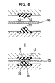
- FIG. 8 is a partial cross sectional view which shows a sealing structure of a fuel cell in accordance with a prior art in a separated state.
- reference numeral 110 denotes a membrane-electrode assembly which is constructed by a high polymer electrolyte membrane, and catalyst electrode layers provided in both sides thereof and the like, and separators 120 are laminated in both sides in a thickness direction of the membrane-electrode assembly 110.
- a gasket 130 integrally provided in the separators 120 in both sides in the thickness direction thereof is brought into close contact with a peripheral edge of the membrane-electrode assembly 110.
- the gasket 130 is made of a rubber-like elastic material (a rubber or a synthetic resin material having a rubber-like elasticity), and a seal protrusion 131 is formed for obtaining a desired surface pressure.
- a desired surface pressure can be secured in a seal surface by the seal protrusion 131 of the gasket 130, however, since the surface pressure is dispersed in a seal surface by the flat seal portion 141 of the gasket 140, and the surface pressure is lowered in comparison with the seal protrusion 131 side, there is such a problem that a desired seal property can not be obtained. Accordingly, in order to compensate for the reduction of the seal property mentioned above, as a sealing structure of a fuel cell in accordance with further the other prior art is shown in Fig.
- a gasket 150 having a seal protrusion 151 and a flat seal portion 152 is provided in the separators 120 in both sides so as to form a swirl shape with each other, and the pinching of the membrane-electrode assembly 110 by the seal protrusion 151 and the flat seal portion 152 is carried out by two positions in a width direction, however, there is such a problem that a width of the gasket 150 becomes large in this case.
- the present invention is made by taking the points mentioned above into consideration, and a technical object thereof is to stabilize a power generating performance of a power generating region as well as securing a stable sealing performance even if an offset due to an assembling precision exists in gaskets in both sides of a membrane-electrode assembly, in a sealing structure of a fuel cell.
- a sealing structure of a fuel cell in accordance with the invention of claim 1 is a sealing structure pinching a membrane-electrode assembly by a first gasket which is integrally provided in a separator arranged in one side in a thickness direction of the membrane-electrode assembly and is made of a rubber-like elastic material, and a second gasket which is integrally provided in a separator arranged in another side in the thickness direction and is made of a rubber-like elastic material, wherein the first gasket has a bank-like main lip which is brought into close contact with the membrane-electrode assembly in its top portion, the second gasket has a flat seal portion which is brought into close contact with the membrane-electrode assembly, and a sub lip which is formed in a bulging manner at an opposed position to the main lip in the flat seal portion, a width of the top portion of the main lip is wider than an assumed maximum offset amount and narrower than a width of the flat seal portion, and the sub
- the membrane-electrode assembly is pinched between the top portion of the main lip of the first gasket, and the flat seal portion and the sub lip of the second gasket, a contact surface pressure of the flat seal portion of the second gasket with respect to the membrane-electrode assembly is compensated by the sub lip. Further, since the width of the top portion of the main lip in the first gasket is narrower than the width of the flat seal portion of the second gasket, a desired contact surface pressure is secured with respect to the membrane-electrode assembly.
- the width of the top portion of the main lip is wider than the assumed maximum offset amount, it is possible to pinch the membrane-electrode assembly by the top portion of the main lip of the first gasket and the flat seal portion and the sub lip of the second gasket, even if any offset is generated on the basis of an assembly precision.
- a sealing structure of a fuel cell in accordance with the invention of claim 2 is structured such that second sub lips are respectively provided in both ends in a width direction of the top portion of the main lip, in the structure described in claim 1.
- the membrane-electrode assembly is pinched by the sub lip, and the second sub lip formed on the end portion in the width direction of the top portion of the main lip. Accordingly, a sufficient contact surface pressure can be secured.
- Fig. 1 is a partly cross sectional view showing a sealing structure of a fuel cell in accordance with a preferable first embodiment of the present invention in a separated state.
- reference numeral 10 denotes a membrane-electrode assembly which is provided with a high polymer electrolyte membrane and catalyst electrode layers arranged in a laminated state in both sides thereof. Separators 20A and 20B are respectively superposed on both sides of the membrane-electrode assembly 10, whereby a fuel cell 1 is constructed.
- a peripheral edge portion 10a of the membrane-electrode assembly 10 is structured such as to be sealed so that a fuel gas (a hydrogen) and an oxidation gas, a water created by an electrochemical reaction so as to be discharged and a surplus oxidation gas, and a cooling medium and the like do not leak from their respective flow paths, by being pinched between a first gasket 30 which is integrally provided in one separator 20A and is made of a rubber-like elastic material (a rubber or a synthetic resin material having a rubber-like elasticity), and a second gasket 40 made of the rubber-like elastic material is integrally provided in another separator 20B.
- a fuel gas a hydrogen
- an oxidation gas a water created by an electrochemical reaction so as to be discharged and a surplus oxidation gas, and a cooling medium and the like
- the first gasket 30 is constructed by a base portion 31 being integrally bonded within a groove 21 formed in one separator 20A, and a bank-like main lip 32 being bulged from the base portion 31 where a top portion 32a of the main lip 32 brought into close contact with the membrane-electrode assembly 10 is formed flat.
- the second gasket 40 is structured such as to have a base portion 41 being integrally bonded within a groove 22 formed in the another separator 20B, a flat seal portion 42 being bulged from the base portion 41, and a sub lip 43 being formed in a bulging manner in the flat seal portion 42.
- the top portion 32a of the main lip 32 in the first gasket 30 is brought into close contact with the membrane-electrode assembly 10, and a width w1 thereof is made wider than an assumed maximum offset amount, and narrower than a width w2 of the flat seal portion 42 in the second gasket 40.
- the sub lip 43 formed in the flat seal portion 42 is formed at an opposed position to the top portion 32a of the main lip 32 in a portion which locally enhances a contact surface pressure with the membrane-electrode assembly 10, and a width w3 thereof is narrower than the width w1 of the top portion 32a of the main lip 32.
- the membrane-electrode assembly 10 comes to a state of being pinched by the top portion 32a of the main lip 32 of the first gasket 30 and the flat seal portion 42 and the sub lip 43 of the second gasket 40 even if the offset ⁇ exists, it is possible to obtain a stable contact surface pressure of the first gasket 30 and the second gasket 40 with respect to the membrane-electrode assembly 10.
- a stable sealing performance can be secure, any great bending moment does not act on the membrane-electrode assembly 10, and reaction forces of the gaskets 30 and 40 do not fluctuate greatly due to the offset ⁇ .
- an influence to a lamination pressure of a power generation region (not shown) existing in a left side in Fig. 1 and Fig. 2 is small. As a result, a stable power generating performance can be secured.
- Fig. 4 is a partly cross sectional view showing a sealing structure of a fuel cell in accordance with a preferable second embodiment of the present invention in a separated state.
- a difference from the first embodiment mentioned above exists in a point that a second sub lip 33 is provided in each of both ends in a width direction of the top portion 32a of the main lip 32 in the first gasket 30.
- the membrane-electrode assembly 10 is pinched by the sub lip 43 and the second sub lip 33, even if the sub lip 43 of the second gasket 40 deviates to the opposed position to the end portion in the width direction in the top portion 32a of the main lip 32 of the first gasket 30 due to the enlargement of the offset on the basis of the assembly precision, a sufficient contact surface pressure can be secured.
- Fig. 5 is a graph showing a result obtained by measuring the contact surface pressure of the gasket with respect to the membrane-electrode assembly, by comparing an embodiment and a comparative example.
- the embodiment employs the same structure in Fig. 1 which is described previously as the first embodiment, as shown in Fig. 6 , and there are measured a contact surface pressure A between the membrane-electrode assembly 10 and the main lip 32 of the first gasket 30 in the portion opposed to the sub lip 43, and a contact surface pressure B between the membrane-electrode assembly 10 and the sub lip 43.
- the comparative example employs the same structure in Fig. 10 which is described previously as the prior art, as shown in Fig.
Landscapes
- Life Sciences & Earth Sciences (AREA)
- Engineering & Computer Science (AREA)
- Manufacturing & Machinery (AREA)
- Sustainable Development (AREA)
- Sustainable Energy (AREA)
- Chemical & Material Sciences (AREA)
- Chemical Kinetics & Catalysis (AREA)
- Electrochemistry (AREA)
- General Chemical & Material Sciences (AREA)
- Fuel Cell (AREA)
Applications Claiming Priority (3)
| Application Number | Priority Date | Filing Date | Title |
|---|---|---|---|
| JP2009120694 | 2009-05-19 | ||
| JP2010029816A JP5617268B2 (ja) | 2009-05-19 | 2010-02-15 | 燃料電池の密封構造 |
| PCT/JP2010/057402 WO2010134421A1 (ja) | 2009-05-19 | 2010-04-27 | 燃料電池の密封構造 |
Publications (3)
| Publication Number | Publication Date |
|---|---|
| EP2434568A1 true EP2434568A1 (de) | 2012-03-28 |
| EP2434568A4 EP2434568A4 (de) | 2012-07-25 |
| EP2434568B1 EP2434568B1 (de) | 2019-01-16 |
Family
ID=43126106
Family Applications (1)
| Application Number | Title | Priority Date | Filing Date |
|---|---|---|---|
| EP10777656.9A Active EP2434568B1 (de) | 2009-05-19 | 2010-04-27 | Versiegelungsstruktur für eine brennstoffzelle |
Country Status (7)
| Country | Link |
|---|---|
| US (1) | US8927174B2 (de) |
| EP (1) | EP2434568B1 (de) |
| JP (1) | JP5617268B2 (de) |
| KR (1) | KR101711034B1 (de) |
| CN (1) | CN102428599B (de) |
| CA (1) | CA2760979C (de) |
| WO (1) | WO2010134421A1 (de) |
Cited By (1)
| Publication number | Priority date | Publication date | Assignee | Title |
|---|---|---|---|---|
| US10511034B2 (en) | 2015-01-30 | 2019-12-17 | Nok Corporation | Gasket for fuel battery |
Families Citing this family (12)
| Publication number | Priority date | Publication date | Assignee | Title |
|---|---|---|---|---|
| AT513834B1 (de) * | 2013-03-01 | 2014-08-15 | Cellstrom Gmbh | Elastomerer Endrahmen einer Redox-Durchflussbatterie |
| KR101470143B1 (ko) * | 2013-04-15 | 2014-12-05 | 현대자동차주식회사 | 연료전지 스택용 가스켓 장치 |
| JP6597552B2 (ja) * | 2016-10-25 | 2019-10-30 | トヨタ自動車株式会社 | ガスケットおよび燃料電池 |
| WO2019012961A1 (ja) * | 2017-07-12 | 2019-01-17 | Nok株式会社 | 二次電池用ガスケット |
| JP7075320B2 (ja) * | 2018-06-05 | 2022-05-25 | Nok株式会社 | 燃料電池用ガスケット |
| JP7075321B2 (ja) * | 2018-09-19 | 2022-05-25 | Nok株式会社 | 燃料電池用ガスケット |
| CN114258604A (zh) * | 2019-08-15 | 2022-03-29 | 罗伯特·博世有限公司 | 用于燃料电池的垫圈及具有这种垫圈的密封装置 |
| CN114373957A (zh) * | 2022-01-18 | 2022-04-19 | 广东国鸿氢能科技有限公司 | 一种燃料电池密封结构 |
| CN114464836B (zh) * | 2022-01-18 | 2026-01-13 | 国鸿氢能科技(嘉兴)股份有限公司 | 一种一体化膜电极燃料电池的密封结构 |
| CN114976088B (zh) * | 2022-05-28 | 2026-01-13 | 北京亿华通科技股份有限公司 | 一种双极板阴阳极气体密封结构、双极板及燃料电池 |
| CN116259777B (zh) * | 2023-05-16 | 2023-09-08 | 中国科学院宁波材料技术与工程研究所 | 一种燃料电池的金属极板及电堆 |
| WO2025204416A1 (ja) * | 2024-03-29 | 2025-10-02 | 本田技研工業株式会社 | 発電セル |
Family Cites Families (10)
| Publication number | Priority date | Publication date | Assignee | Title |
|---|---|---|---|---|
| AU5247100A (en) * | 1999-07-13 | 2001-01-30 | Nok Corporation | Gasket for fuel cell and method of forming it |
| CN100487966C (zh) * | 2000-06-29 | 2009-05-13 | Nok株式会社 | 燃料电池构成部件 |
| JP3400415B2 (ja) | 2000-07-25 | 2003-04-28 | 本田技研工業株式会社 | 燃料電池のシール構造 |
| JP2005158424A (ja) * | 2003-11-25 | 2005-06-16 | Nissan Motor Co Ltd | 燃料電池 |
| JP2005197086A (ja) * | 2004-01-07 | 2005-07-21 | Uchiyama Mfg Corp | 燃料電池用ガスケット |
| US7524573B2 (en) | 2004-02-23 | 2009-04-28 | Kabushiki Kaisha Toshiba | Fuel cell having inner and outer periphery seal members |
| JP2005276820A (ja) * | 2004-02-23 | 2005-10-06 | Toshiba Corp | 燃料電池 |
| JP2008004278A (ja) * | 2006-06-20 | 2008-01-10 | Toshiba Corp | 燃料電池シール及び燃料電池 |
| JP5077528B2 (ja) | 2006-10-10 | 2012-11-21 | Nok株式会社 | 燃料電池用ガスケット |
| JP5170376B2 (ja) * | 2007-08-03 | 2013-03-27 | Nok株式会社 | 燃料電池の密封構造 |
-
2010
- 2010-02-15 JP JP2010029816A patent/JP5617268B2/ja active Active
- 2010-04-27 CA CA2760979A patent/CA2760979C/en active Active
- 2010-04-27 EP EP10777656.9A patent/EP2434568B1/de active Active
- 2010-04-27 WO PCT/JP2010/057402 patent/WO2010134421A1/ja not_active Ceased
- 2010-04-27 KR KR1020117026592A patent/KR101711034B1/ko active Active
- 2010-04-27 CN CN201080022024.7A patent/CN102428599B/zh active Active
- 2010-04-27 US US13/320,886 patent/US8927174B2/en active Active
Cited By (1)
| Publication number | Priority date | Publication date | Assignee | Title |
|---|---|---|---|---|
| US10511034B2 (en) | 2015-01-30 | 2019-12-17 | Nok Corporation | Gasket for fuel battery |
Also Published As
| Publication number | Publication date |
|---|---|
| KR20120022892A (ko) | 2012-03-12 |
| EP2434568A4 (de) | 2012-07-25 |
| JP5617268B2 (ja) | 2014-11-05 |
| CN102428599B (zh) | 2015-07-08 |
| WO2010134421A1 (ja) | 2010-11-25 |
| CA2760979A1 (en) | 2010-11-25 |
| CN102428599A (zh) | 2012-04-25 |
| US8927174B2 (en) | 2015-01-06 |
| CA2760979C (en) | 2014-03-18 |
| US20120064429A1 (en) | 2012-03-15 |
| EP2434568B1 (de) | 2019-01-16 |
| JP2011003528A (ja) | 2011-01-06 |
| KR101711034B1 (ko) | 2017-02-28 |
Similar Documents
| Publication | Publication Date | Title |
|---|---|---|
| EP2434568B1 (de) | Versiegelungsstruktur für eine brennstoffzelle | |
| EP2309577B1 (de) | Elektrolytmembran/elektrodenstruktur und brennstoffzelle | |
| EP2341573B1 (de) | Dichtungsstruktur für eine brennstoffzelle | |
| EP2445046B1 (de) | Versiegelungsstruktur für eine brennstoffzelle | |
| US9799898B2 (en) | Fuel cell | |
| US9673458B2 (en) | Fuel cell | |
| JP5170376B2 (ja) | 燃料電池の密封構造 | |
| US9196911B2 (en) | Fuel cell gas diffusion layer integrated gasket | |
| JP6082362B2 (ja) | 燃料電池 | |
| US10003098B2 (en) | Fuel cell | |
| KR20130057716A (ko) | 고분자 전해질 연료전지용 분리판 및 이것을 이용한 고분자 전해질 연료전지 | |
| US20140080030A1 (en) | Fuel cell | |
| JP4998656B2 (ja) | 燃料電池セルの密封構造 | |
| JP5447762B2 (ja) | 燃料電池セル部品 | |
| US9350034B2 (en) | Fuel cell gas diffusion layer integrated gasket | |
| JP2011134559A (ja) | 固体高分子型燃料電池 | |
| JP2006107985A (ja) | 燃料電池 | |
| JP2006120547A (ja) | 燃料電池 |
Legal Events
| Date | Code | Title | Description |
|---|---|---|---|
| PUAI | Public reference made under article 153(3) epc to a published international application that has entered the european phase |
Free format text: ORIGINAL CODE: 0009012 |
|
| 17P | Request for examination filed |
Effective date: 20111117 |
|
| AK | Designated contracting states |
Kind code of ref document: A1 Designated state(s): AT BE BG CH CY CZ DE DK EE ES FI FR GB GR HR HU IE IS IT LI LT LU LV MC MK MT NL NO PL PT RO SE SI SK SM TR |
|
| A4 | Supplementary search report drawn up and despatched |
Effective date: 20120627 |
|
| RIC1 | Information provided on ipc code assigned before grant |
Ipc: H01M 8/10 20060101ALI20120621BHEP Ipc: H01M 8/02 20060101AFI20120621BHEP |
|
| DAX | Request for extension of the european patent (deleted) | ||
| 17Q | First examination report despatched |
Effective date: 20151117 |
|
| STAA | Information on the status of an ep patent application or granted ep patent |
Free format text: STATUS: EXAMINATION IS IN PROGRESS |
|
| GRAP | Despatch of communication of intention to grant a patent |
Free format text: ORIGINAL CODE: EPIDOSNIGR1 |
|
| STAA | Information on the status of an ep patent application or granted ep patent |
Free format text: STATUS: GRANT OF PATENT IS INTENDED |
|
| INTG | Intention to grant announced |
Effective date: 20180806 |
|
| GRAS | Grant fee paid |
Free format text: ORIGINAL CODE: EPIDOSNIGR3 |
|
| GRAA | (expected) grant |
Free format text: ORIGINAL CODE: 0009210 |
|
| STAA | Information on the status of an ep patent application or granted ep patent |
Free format text: STATUS: THE PATENT HAS BEEN GRANTED |
|
| AK | Designated contracting states |
Kind code of ref document: B1 Designated state(s): AT BE BG CH CY CZ DE DK EE ES FI FR GB GR HR HU IE IS IT LI LT LU LV MC MK MT NL NO PL PT RO SE SI SK SM TR |
|
| REG | Reference to a national code |
Ref country code: GB Ref legal event code: FG4D |
|
| REG | Reference to a national code |
Ref country code: CH Ref legal event code: EP |
|
| REG | Reference to a national code |
Ref country code: IE Ref legal event code: FG4D |
|
| REG | Reference to a national code |
Ref country code: DE Ref legal event code: R096 Ref document number: 602010056610 Country of ref document: DE |
|
| REG | Reference to a national code |
Ref country code: AT Ref legal event code: REF Ref document number: 1090399 Country of ref document: AT Kind code of ref document: T Effective date: 20190215 |
|
| REG | Reference to a national code |
Ref country code: NL Ref legal event code: MP Effective date: 20190116 |
|
| REG | Reference to a national code |
Ref country code: LT Ref legal event code: MG4D |
|
| PG25 | Lapsed in a contracting state [announced via postgrant information from national office to epo] |
Ref country code: NL Free format text: LAPSE BECAUSE OF FAILURE TO SUBMIT A TRANSLATION OF THE DESCRIPTION OR TO PAY THE FEE WITHIN THE PRESCRIBED TIME-LIMIT Effective date: 20190116 |
|
| REG | Reference to a national code |
Ref country code: AT Ref legal event code: MK05 Ref document number: 1090399 Country of ref document: AT Kind code of ref document: T Effective date: 20190116 |
|
| PG25 | Lapsed in a contracting state [announced via postgrant information from national office to epo] |
Ref country code: NO Free format text: LAPSE BECAUSE OF FAILURE TO SUBMIT A TRANSLATION OF THE DESCRIPTION OR TO PAY THE FEE WITHIN THE PRESCRIBED TIME-LIMIT Effective date: 20190416 Ref country code: FI Free format text: LAPSE BECAUSE OF FAILURE TO SUBMIT A TRANSLATION OF THE DESCRIPTION OR TO PAY THE FEE WITHIN THE PRESCRIBED TIME-LIMIT Effective date: 20190116 Ref country code: PT Free format text: LAPSE BECAUSE OF FAILURE TO SUBMIT A TRANSLATION OF THE DESCRIPTION OR TO PAY THE FEE WITHIN THE PRESCRIBED TIME-LIMIT Effective date: 20190516 Ref country code: SE Free format text: LAPSE BECAUSE OF FAILURE TO SUBMIT A TRANSLATION OF THE DESCRIPTION OR TO PAY THE FEE WITHIN THE PRESCRIBED TIME-LIMIT Effective date: 20190116 Ref country code: PL Free format text: LAPSE BECAUSE OF FAILURE TO SUBMIT A TRANSLATION OF THE DESCRIPTION OR TO PAY THE FEE WITHIN THE PRESCRIBED TIME-LIMIT Effective date: 20190116 Ref country code: ES Free format text: LAPSE BECAUSE OF FAILURE TO SUBMIT A TRANSLATION OF THE DESCRIPTION OR TO PAY THE FEE WITHIN THE PRESCRIBED TIME-LIMIT Effective date: 20190116 Ref country code: LT Free format text: LAPSE BECAUSE OF FAILURE TO SUBMIT A TRANSLATION OF THE DESCRIPTION OR TO PAY THE FEE WITHIN THE PRESCRIBED TIME-LIMIT Effective date: 20190116 |
|
| PG25 | Lapsed in a contracting state [announced via postgrant information from national office to epo] |
Ref country code: LV Free format text: LAPSE BECAUSE OF FAILURE TO SUBMIT A TRANSLATION OF THE DESCRIPTION OR TO PAY THE FEE WITHIN THE PRESCRIBED TIME-LIMIT Effective date: 20190116 Ref country code: HR Free format text: LAPSE BECAUSE OF FAILURE TO SUBMIT A TRANSLATION OF THE DESCRIPTION OR TO PAY THE FEE WITHIN THE PRESCRIBED TIME-LIMIT Effective date: 20190116 Ref country code: IS Free format text: LAPSE BECAUSE OF FAILURE TO SUBMIT A TRANSLATION OF THE DESCRIPTION OR TO PAY THE FEE WITHIN THE PRESCRIBED TIME-LIMIT Effective date: 20190516 Ref country code: GR Free format text: LAPSE BECAUSE OF FAILURE TO SUBMIT A TRANSLATION OF THE DESCRIPTION OR TO PAY THE FEE WITHIN THE PRESCRIBED TIME-LIMIT Effective date: 20190417 Ref country code: BG Free format text: LAPSE BECAUSE OF FAILURE TO SUBMIT A TRANSLATION OF THE DESCRIPTION OR TO PAY THE FEE WITHIN THE PRESCRIBED TIME-LIMIT Effective date: 20190416 |
|
| PGFP | Annual fee paid to national office [announced via postgrant information from national office to epo] |
Ref country code: FR Payment date: 20190423 Year of fee payment: 10 |
|
| REG | Reference to a national code |
Ref country code: DE Ref legal event code: R097 Ref document number: 602010056610 Country of ref document: DE |
|
| PG25 | Lapsed in a contracting state [announced via postgrant information from national office to epo] |
Ref country code: AT Free format text: LAPSE BECAUSE OF FAILURE TO SUBMIT A TRANSLATION OF THE DESCRIPTION OR TO PAY THE FEE WITHIN THE PRESCRIBED TIME-LIMIT Effective date: 20190116 Ref country code: DK Free format text: LAPSE BECAUSE OF FAILURE TO SUBMIT A TRANSLATION OF THE DESCRIPTION OR TO PAY THE FEE WITHIN THE PRESCRIBED TIME-LIMIT Effective date: 20190116 Ref country code: EE Free format text: LAPSE BECAUSE OF FAILURE TO SUBMIT A TRANSLATION OF THE DESCRIPTION OR TO PAY THE FEE WITHIN THE PRESCRIBED TIME-LIMIT Effective date: 20190116 Ref country code: CZ Free format text: LAPSE BECAUSE OF FAILURE TO SUBMIT A TRANSLATION OF THE DESCRIPTION OR TO PAY THE FEE WITHIN THE PRESCRIBED TIME-LIMIT Effective date: 20190116 Ref country code: IT Free format text: LAPSE BECAUSE OF FAILURE TO SUBMIT A TRANSLATION OF THE DESCRIPTION OR TO PAY THE FEE WITHIN THE PRESCRIBED TIME-LIMIT Effective date: 20190116 Ref country code: RO Free format text: LAPSE BECAUSE OF FAILURE TO SUBMIT A TRANSLATION OF THE DESCRIPTION OR TO PAY THE FEE WITHIN THE PRESCRIBED TIME-LIMIT Effective date: 20190116 Ref country code: SK Free format text: LAPSE BECAUSE OF FAILURE TO SUBMIT A TRANSLATION OF THE DESCRIPTION OR TO PAY THE FEE WITHIN THE PRESCRIBED TIME-LIMIT Effective date: 20190116 |
|
| PGFP | Annual fee paid to national office [announced via postgrant information from national office to epo] |
Ref country code: GB Payment date: 20190424 Year of fee payment: 10 |
|
| PLBE | No opposition filed within time limit |
Free format text: ORIGINAL CODE: 0009261 |
|
| STAA | Information on the status of an ep patent application or granted ep patent |
Free format text: STATUS: NO OPPOSITION FILED WITHIN TIME LIMIT |
|
| PG25 | Lapsed in a contracting state [announced via postgrant information from national office to epo] |
Ref country code: SM Free format text: LAPSE BECAUSE OF FAILURE TO SUBMIT A TRANSLATION OF THE DESCRIPTION OR TO PAY THE FEE WITHIN THE PRESCRIBED TIME-LIMIT Effective date: 20190116 |
|
| REG | Reference to a national code |
Ref country code: CH Ref legal event code: PL |
|
| REG | Reference to a national code |
Ref country code: BE Ref legal event code: MM Effective date: 20190430 |
|
| 26N | No opposition filed |
Effective date: 20191017 |
|
| PG25 | Lapsed in a contracting state [announced via postgrant information from national office to epo] |
Ref country code: LU Free format text: LAPSE BECAUSE OF NON-PAYMENT OF DUE FEES Effective date: 20190427 Ref country code: MC Free format text: LAPSE BECAUSE OF FAILURE TO SUBMIT A TRANSLATION OF THE DESCRIPTION OR TO PAY THE FEE WITHIN THE PRESCRIBED TIME-LIMIT Effective date: 20190116 |
|
| PG25 | Lapsed in a contracting state [announced via postgrant information from national office to epo] |
Ref country code: CH Free format text: LAPSE BECAUSE OF NON-PAYMENT OF DUE FEES Effective date: 20190430 Ref country code: LI Free format text: LAPSE BECAUSE OF NON-PAYMENT OF DUE FEES Effective date: 20190430 |
|
| PG25 | Lapsed in a contracting state [announced via postgrant information from national office to epo] |
Ref country code: BE Free format text: LAPSE BECAUSE OF NON-PAYMENT OF DUE FEES Effective date: 20190430 Ref country code: SI Free format text: LAPSE BECAUSE OF FAILURE TO SUBMIT A TRANSLATION OF THE DESCRIPTION OR TO PAY THE FEE WITHIN THE PRESCRIBED TIME-LIMIT Effective date: 20190116 |
|
| PG25 | Lapsed in a contracting state [announced via postgrant information from national office to epo] |
Ref country code: TR Free format text: LAPSE BECAUSE OF FAILURE TO SUBMIT A TRANSLATION OF THE DESCRIPTION OR TO PAY THE FEE WITHIN THE PRESCRIBED TIME-LIMIT Effective date: 20190116 |
|
| PG25 | Lapsed in a contracting state [announced via postgrant information from national office to epo] |
Ref country code: IE Free format text: LAPSE BECAUSE OF NON-PAYMENT OF DUE FEES Effective date: 20190427 |
|
| PG25 | Lapsed in a contracting state [announced via postgrant information from national office to epo] |
Ref country code: FR Free format text: LAPSE BECAUSE OF NON-PAYMENT OF DUE FEES Effective date: 20200430 |
|
| GBPC | Gb: european patent ceased through non-payment of renewal fee |
Effective date: 20200427 |
|
| PG25 | Lapsed in a contracting state [announced via postgrant information from national office to epo] |
Ref country code: GB Free format text: LAPSE BECAUSE OF NON-PAYMENT OF DUE FEES Effective date: 20200427 |
|
| PG25 | Lapsed in a contracting state [announced via postgrant information from national office to epo] |
Ref country code: CY Free format text: LAPSE BECAUSE OF FAILURE TO SUBMIT A TRANSLATION OF THE DESCRIPTION OR TO PAY THE FEE WITHIN THE PRESCRIBED TIME-LIMIT Effective date: 20190116 |
|
| PG25 | Lapsed in a contracting state [announced via postgrant information from national office to epo] |
Ref country code: HU Free format text: LAPSE BECAUSE OF FAILURE TO SUBMIT A TRANSLATION OF THE DESCRIPTION OR TO PAY THE FEE WITHIN THE PRESCRIBED TIME-LIMIT; INVALID AB INITIO Effective date: 20100427 Ref country code: MT Free format text: LAPSE BECAUSE OF FAILURE TO SUBMIT A TRANSLATION OF THE DESCRIPTION OR TO PAY THE FEE WITHIN THE PRESCRIBED TIME-LIMIT Effective date: 20190116 |
|
| PG25 | Lapsed in a contracting state [announced via postgrant information from national office to epo] |
Ref country code: MK Free format text: LAPSE BECAUSE OF FAILURE TO SUBMIT A TRANSLATION OF THE DESCRIPTION OR TO PAY THE FEE WITHIN THE PRESCRIBED TIME-LIMIT Effective date: 20190116 |
|
| PGFP | Annual fee paid to national office [announced via postgrant information from national office to epo] |
Ref country code: DE Payment date: 20250305 Year of fee payment: 16 |