EP2433803A1 - Printing device fluid reservoir with gripping features - Google Patents
Printing device fluid reservoir with gripping features Download PDFInfo
- Publication number
- EP2433803A1 EP2433803A1 EP11195093A EP11195093A EP2433803A1 EP 2433803 A1 EP2433803 A1 EP 2433803A1 EP 11195093 A EP11195093 A EP 11195093A EP 11195093 A EP11195093 A EP 11195093A EP 2433803 A1 EP2433803 A1 EP 2433803A1
- Authority
- EP
- European Patent Office
- Prior art keywords
- fluid reservoir
- fluid
- lever
- chassis
- containing body
- Prior art date
- Legal status (The legal status is an assumption and is not a legal conclusion. Google has not performed a legal analysis and makes no representation as to the accuracy of the status listed.)
- Withdrawn
Links
Images


Classifications
-
- B—PERFORMING OPERATIONS; TRANSPORTING
- B41—PRINTING; LINING MACHINES; TYPEWRITERS; STAMPS
- B41J—TYPEWRITERS; SELECTIVE PRINTING MECHANISMS, i.e. MECHANISMS PRINTING OTHERWISE THAN FROM A FORME; CORRECTION OF TYPOGRAPHICAL ERRORS
- B41J2/00—Typewriters or selective printing mechanisms characterised by the printing or marking process for which they are designed
- B41J2/005—Typewriters or selective printing mechanisms characterised by the printing or marking process for which they are designed characterised by bringing liquid or particles selectively into contact with a printing material
- B41J2/01—Ink jet
- B41J2/17—Ink jet characterised by ink handling
- B41J2/175—Ink supply systems ; Circuit parts therefor
- B41J2/17503—Ink cartridges
- B41J2/17513—Inner structure
-
- B—PERFORMING OPERATIONS; TRANSPORTING
- B41—PRINTING; LINING MACHINES; TYPEWRITERS; STAMPS
- B41J—TYPEWRITERS; SELECTIVE PRINTING MECHANISMS, i.e. MECHANISMS PRINTING OTHERWISE THAN FROM A FORME; CORRECTION OF TYPOGRAPHICAL ERRORS
- B41J2/00—Typewriters or selective printing mechanisms characterised by the printing or marking process for which they are designed
- B41J2/005—Typewriters or selective printing mechanisms characterised by the printing or marking process for which they are designed characterised by bringing liquid or particles selectively into contact with a printing material
- B41J2/01—Ink jet
- B41J2/17—Ink jet characterised by ink handling
- B41J2/175—Ink supply systems ; Circuit parts therefor
- B41J2/17503—Ink cartridges
- B41J2/1752—Mounting within the printer
Definitions
- This invention pertains to a printing device fluid reservoir with gripping features.
- this invention pertains to gripping features for a fluid reservoir that facilitate holding, insertion of, and removal of the fluid reservoir from a chassis.
- Fluid-ejection printing devices such as ink jet printers, commonly have at least one fluid reservoir and a chassis that supports the fluid reservoir.
- the combination of the fluid reservoir and the chassis is referred to herein as a "fluid-providing system.”
- the fluid reservoir may contain one or more fluid chambers that provide fluid to a printhead. If the fluid reservoir has more than one ink chamber, each such chamber often retains fluid of a different color for multi-color printing. On the other hand, if the fluid reservoir has only a single ink chamber, typically such chamber is used to retain black ink for black-and-white printing.
- the printhead commonly is connected directly or indirectly to the chassis.
- the printhead along with the chassis and the fluid reservoir, typically are moved in a lateral direction across a width of a substrate, such as paper, as fluid is ejected from the printhead.
- the substrate is advanced in a direction perpendicular to the lateral direction along a length of the substrate, so that the printhead can form a subsequent row-portion of the image. This process of advancing the substrate for each row-portion is repeated until a next substrate is needed or the image is completed.
- the fluid reservoir includes a first surface and a fluid-containing body located beneath the first surface when the fluid reservoir is in an orientation in which it is configured to operate.
- the first surface includes a protruding grip
- the fluid-containing body has a lever extending therefrom.
- both the protruding grip and the lever are configured to receive a pinching force that compresses the lever towards the fluid-containing body, facilitates carrying of the fluid reservoir, and facilitates installing and/or releasing the fluid reservoir into/from a chassis of the printing device.
- the protruding grip extends horizontally or substantially horizontally beyond an edge of the fluid containing body.
- the protruding grip may be flat or substantially flat, which may make the fluid reservoir easier to fit into a printing device. Further in this regard, the protruding grip and the first surface of the fluid reservoir form a single flat or substantially flat surface, which also may make the fluid reservoir easier to fit into a printing device.
- the protruding grip may be curved (along with or separate from the first surface of the fluid reservoir) to facilitate better interaction with a finger applying a pinching force. Further, the protruding grip may include a textured region to facilitate gripping and interaction with a finger applying the pinching force.
- the lever extending from the fluid-containing body may be located at least in part beneath the protruding grip when the fluid reservoir is in an orientation in which it is configured to operate.
- the lever may extend further from the fluid-containing body than the protruding grip does.
- the lever may extend the same or substantially the same distance from the fluid-containing body or less than the distance from the fluid-containing body than the protruding grip does.
- the lever is configured to retain a finger by its shape.
- the lever may have a pinching-force-reception region that is concave to assist it in facilitating reception of a finger applying the pinching force.
- the lever and, optionally, the chassis are formed of a material and/or are arranged in a configuration that generates an audible sound when the fluid reservoir is properly inserted into the chassis of the printing device.
- a user receives instant and audible feedback regarding when the fluid reservoir is properly inserted into the chassis.
- sensing devices may be included with the printing device to monitor and determine whether such an audible click has been produced, in order to determine whether the fluid reservoir has been properly inserted into the supporting chassis.
- Embodiments of the present invention provide a protruding grip and lever combination configured to receive a pinching force, by which the fluid reservoir may easily be carried, inserted into a supporting chassis, or removed from the supporting chassis.
- additional features such as a flat or substantially flat protruding grip, a curved protruding grip, texture on the protruding grip, a proper curvature of the pinching-force-application surface of the lever, and an audible click when the lever snaps into an engaged position in the chassis provide additional benefits in their own right and need not be used in combination with the other features described herein.
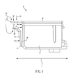
- Such fluid reservoir 2 includes a single, internal, fluid chamber (not shown) configured to retain fluid.
- the fluid chamber may be used to retain black ink for black-and-white printing.
- the fluid reservoir 2 has a first or top surface 4 from which a grip 6 protrudes (also referred to as a "protruding grip").
- the protruding grip 6, according to the embodiment of FIG. 1 , extends horizontally or substantially horizontally beyond an edge 14 of the fluid-containing body 8.
- the embodiment of FIG. 1 illustrates the first surface 4 and the protruding grip 6 as forming a single flat surface, one skilled in the art will appreciate that such a configuration is not required.
- the protruding grip 6 may be curved in a shape that facilitates interaction with a finger applying a pinching force 12.
- a flat or substantially flat first surface 4 and protruding grip 6 may be beneficial in certain implementations and may improve the ease in which the fluid reservoir 2 fits inside a printing device (not shown).
- the fluid reservoir 2 includes a fluid-containing body 8 that is located beneath the first surface 4 when the fluid reservoir 2 is oriented in a configuration in which the fluid reservoir 2 is designed to operate.
- the fluid reservoir 2 is configured to be oriented in a horizontal direction 7 while operating, i.e., such that the top surface 4 is substantially aligned along a horizontal direction 7.
- a lever 10 extends from a surface 18 of the fluid-containing body 8 at a point of attachment 9. The combination of the protruding grip 6 and the lever 10 are configured to receive the pinching force 12 to facilitate carrying the fluid reservoir 2, inserting the fluid reservoir 2 into a chassis 24 (shown in FIGs.
- a pinching-force-application portion 21 of the lever 10 may be curved concavely so that it approaches being parallel or substantially parallel to protruding grip 6, in order to facilitate receiving a finger applying the pinching force 12.
- a portion of lever 10 is perpendicular or substantially perpendicular to top surface 4
- a region of pinching-force-application portion 21 is parallel or substantially parallel to top surface 4.
- pinching-force-application surface 20 of portion 21 may be textured or otherwise provided with a friction-inducing surface, such as, for example, a tacky surface or elastomeric surface, for more reliable gripping.
- the protruding grip 6 may have region 16 thereon, such that region 16 may facilitate interaction with a finger applying the pinching force 12 thereon.
- region 16 may be textured or otherwise provided with a friction-inducing surface for more reliable gripping.
- region 16 may be located in a depression in protruding grip 6.
- finger is used generically and may refer to either a finger or a thumb. Typically the thumb would be applied to protruding grip 6 and the index finger would be applied to pinching-force-application surface 20, but other gripping arrangements are possible, so the word finger is used here as well as in the claims.
- the combination of the protruding grip 6 and the lever 10 are configured to receive a pinching force 12 in a direction perpendicular or substantially perpendicular to the protruding grip 6 and the pinching-force-application surface 20. Further, the combination of the protruding grip 6 and the surface 20 of lever 10 may be configured to receive a pinching force 12 in a direction parallel or substantially parallel to an initial direction 25 in which the fluid reservoir 2 is removed from a chassis 24 (see FIGs. 3 and 4 ).
- An advantage of this arrangement is that it allows a user to apply the pinching force 12 and then lift the fluid reservoir 2 in the initial direction 25 to remove it from the chassis 24 while the protruding grip 6 and the lever 10 support the lifting motion.
- portion 21 of lever 10 that is substantially parallel or substantially parallel to protruding grip 6 preferably is designed to extend a minimum of 4 mm in a direction that is perpendicular or substantially perpendicular to surface 18.
- portion 21 is designed to extend a minimum distance of 10 mm from surface 18, including the gap between lever 10 and surface 18.
- the multi-chambered fluid reservoir 3 includes the same or similar features as the single-chambered fluid reservoir 2 in FIG. 1 , except that the multi-chambered fluid reservoir 3 is wider and includes multiple separate chambers (not shown), each for retaining its own supply of fluid.
- each chamber may be used to retain cyan, magenta, yellow, and black inks, respectively, for multi-color printing.
- the top surface 4 and protruding grip 6 may consist of a lid or cover which is affixed to fluid containing body 8.
- the lid 4,6 may be affixed to body 8 by welding or adhesive prior to filling body 8 with fluid.
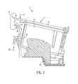
- FIGs. 3 and 4 illustrate a fluid-providing system 1, according to an embodiment of the present invention.
- FIGs. 3 and 4 illustrate the insertion of the multi-chambered fluid reservoir 3 into the chassis 24, according to an embodiment of the present invention.
- the pinching force 12 may be applied to the protruding grip 6 and the lever 10 to carry the fluid reservoir 3 to the position shown in FIG. 3 .
- the lever 10 need not be depressed, and a downward pressing force 15 may be applied to the protruding grip 6 to push the fluid reservoir 3 into the chassis 24.
- the fluid reservoir 3 engages into the chassis 24 as shown in FIG. 4 .
- FIG. 4 represents the fluid reservoir 3 inserted into the chassis 24, and not all of the forces or sounds are applicable at the same time.
- the pinching force 12 is applied, but when the fluid reservoir 3 engages in the chassis 24 as shown in FIG. 4 , the pinching force 12 is typically released and the pressing force 15 is applied.
- FIG. 4 shows pinching force 12 is that this is the force required when removing fluid reservoir 3 from chassis 24. At this time, there is no pressing force 15 applied and a less loud sound results as the latch is disengaged.
- the lever 10 is made of a material and has a configuration that produces an audible click sound 22
- the chassis 24 is made of a relatively stiff plastic that is injection moldable, such as glass-filled polyphenylene oxide. Fluid reservoir 3 and its attached lever 10 are preferably injection molded from a single plastic material such as polypropylene.
- the pinching force 12 is applied to the protruding grip 6 and the pinching-force-application surface 20 of the lever 10 to compress the lever 10 towards the fluid containing body 14, thereby releasing the latch 13 from the chassis 24. Such release allows the fluid reservoir 3 to be removed from the chassis 24.
Landscapes
- Ink Jet (AREA)
Applications Claiming Priority (2)
| Application Number | Priority Date | Filing Date | Title |
|---|---|---|---|
| US11/614,147 US7690774B2 (en) | 2006-12-21 | 2006-12-21 | Printing device fluid reservoir with gripping features |
| EP07862613.2A EP2094493B1 (en) | 2006-12-21 | 2007-12-06 | Printing device fluid reservoir with gripping features |
Related Parent Applications (1)
| Application Number | Title | Priority Date | Filing Date |
|---|---|---|---|
| EP07862613.2 Division | 2007-12-06 |
Publications (1)
| Publication Number | Publication Date |
|---|---|
| EP2433803A1 true EP2433803A1 (en) | 2012-03-28 |
Family
ID=39154120
Family Applications (3)
| Application Number | Title | Priority Date | Filing Date |
|---|---|---|---|
| EP11195093A Withdrawn EP2433803A1 (en) | 2006-12-21 | 2007-12-06 | Printing device fluid reservoir with gripping features |
| EP11195094A Withdrawn EP2433804A1 (en) | 2006-12-21 | 2007-12-06 | Printing device fluid reservoir with gripping features |
| EP07862613.2A Not-in-force EP2094493B1 (en) | 2006-12-21 | 2007-12-06 | Printing device fluid reservoir with gripping features |
Family Applications After (2)
| Application Number | Title | Priority Date | Filing Date |
|---|---|---|---|
| EP11195094A Withdrawn EP2433804A1 (en) | 2006-12-21 | 2007-12-06 | Printing device fluid reservoir with gripping features |
| EP07862613.2A Not-in-force EP2094493B1 (en) | 2006-12-21 | 2007-12-06 | Printing device fluid reservoir with gripping features |
Country Status (6)
| Country | Link |
|---|---|
| US (3) | US7690774B2 (enExample) |
| EP (3) | EP2433803A1 (enExample) |
| JP (3) | JP2010513094A (enExample) |
| CN (1) | CN101600576B (enExample) |
| TW (3) | TW201206715A (enExample) |
| WO (1) | WO2008076227A1 (enExample) |
Families Citing this family (12)
| Publication number | Priority date | Publication date | Assignee | Title |
|---|---|---|---|---|
| US7810917B2 (en) * | 2006-12-21 | 2010-10-12 | Eastman Kodak Company | Printing device fluid reservoir with alignment features |
| US7976138B2 (en) * | 2006-12-21 | 2011-07-12 | Eastman Kodak Company | Data-providing-component securing mechanism for printing apparatus reservoir |
| US7690774B2 (en) * | 2006-12-21 | 2010-04-06 | Eastman Kodak Company | Printing device fluid reservoir with gripping features |
| US8246141B2 (en) * | 2006-12-21 | 2012-08-21 | Eastman Kodak Company | Insert molded printhead substrate |
| FR2957727B1 (fr) | 2010-03-22 | 2012-03-09 | Legrand France | Support de rail de montage d'appareillages electriques dans un coffret electrique |
| US8469490B2 (en) | 2011-10-26 | 2013-06-25 | Eastman Kodak Company | Ink tank configuration for inkjet printer |
| WO2013062860A1 (en) | 2011-10-26 | 2013-05-02 | Eastman Kodak Company | Ink distribution configuration for carriage inkjet printer |
| JP6079362B2 (ja) * | 2013-03-27 | 2017-02-15 | ブラザー工業株式会社 | 印刷流体供給装置及び印刷流体カートリッジ |
| JP6202052B2 (ja) * | 2014-08-29 | 2017-09-27 | セイコーエプソン株式会社 | 液体供給ユニット |
| JP6753054B2 (ja) * | 2015-11-27 | 2020-09-09 | セイコーエプソン株式会社 | 液体収容容器および保護部材 |
| USD934341S1 (en) | 2018-12-03 | 2021-10-26 | Hewlett-Packard Development Company, L.P. | Ink cartridge |
| JP7322465B2 (ja) * | 2019-03-29 | 2023-08-08 | ブラザー工業株式会社 | 画像形成装置 |
Citations (5)
| Publication number | Priority date | Publication date | Assignee | Title |
|---|---|---|---|---|
| WO2001054911A1 (en) * | 2000-01-31 | 2001-08-02 | Hewlett-Packard Company | Latch and handle arrangement for a replaceable ink container |
| US20030035035A1 (en) * | 1999-10-06 | 2003-02-20 | Komplin Steven Robert | Replaceable ink cartridge for ink jet pen |
| US6623104B1 (en) * | 1999-10-04 | 2003-09-23 | Canon Kabushiki Kaisha | Liquid container, cap used with the liquid container, and cap-equipped liquid container |
| US20040135857A1 (en) * | 2002-11-26 | 2004-07-15 | Kazuhiro Hashii | Ink cartridge and recording apparatus |
| EP1512536A1 (en) * | 2002-06-11 | 2005-03-09 | Seiko Epson Corporation | Ink cartridge |
Family Cites Families (9)
| Publication number | Priority date | Publication date | Assignee | Title |
|---|---|---|---|---|
| US5646654A (en) * | 1995-03-09 | 1997-07-08 | Hewlett-Packard Company | Ink-jet printing system having acoustic transducer for determining optimum operating energy |
| US6454400B1 (en) * | 1998-09-01 | 2002-09-24 | Canon Kabushiki Kaisha | Liquid container, cartridge including liquid container, printing apparatus using cartridge and liquid discharge printing apparatus |
| JP3706776B2 (ja) * | 1998-09-03 | 2005-10-19 | キヤノン株式会社 | インクタンク、タンクホルダ、インクジェットヘッドカートリッジ、およびインクジェット記録装置 |
| US6390601B1 (en) * | 1998-10-27 | 2002-05-21 | Canon Kabushiki Kaisha | Ink tank, ink jet head cartridge, and ink jet recording apparatus |
| JP2001353878A (ja) * | 2000-06-13 | 2001-12-25 | Canon Inc | 吐出用液体収納容器および液体吐出記録装置 |
| JP2002079674A (ja) | 2000-09-04 | 2002-03-19 | Canon Inc | 液体吐出ヘッドユニット、ヘッドカートリッジおよび液体吐出ヘッドユニットの製造方法 |
| JP2004122487A (ja) * | 2002-09-30 | 2004-04-22 | Canon Inc | 液体タンクおよびタンクホルダ、ヘッドカートリッジ、記録装置、タンク着脱方法 |
| ES2303151T3 (es) * | 2002-11-26 | 2008-08-01 | Seiko Epson Corporation | Cartucho de tinta. |
| US7690774B2 (en) * | 2006-12-21 | 2010-04-06 | Eastman Kodak Company | Printing device fluid reservoir with gripping features |
-
2006
- 2006-12-21 US US11/614,147 patent/US7690774B2/en not_active Expired - Fee Related
-
2007
- 2007-12-06 EP EP11195093A patent/EP2433803A1/en not_active Withdrawn
- 2007-12-06 EP EP11195094A patent/EP2433804A1/en not_active Withdrawn
- 2007-12-06 EP EP07862613.2A patent/EP2094493B1/en not_active Not-in-force
- 2007-12-06 JP JP2009542793A patent/JP2010513094A/ja active Pending
- 2007-12-06 WO PCT/US2007/025028 patent/WO2008076227A1/en not_active Ceased
- 2007-12-06 CN CN2007800472852A patent/CN101600576B/zh not_active Expired - Fee Related
- 2007-12-20 TW TW100128256A patent/TW201206715A/zh unknown
- 2007-12-20 TW TW100128254A patent/TW201202051A/zh unknown
- 2007-12-20 TW TW096149076A patent/TW200836933A/zh unknown
-
2010
- 2010-02-15 US US12/705,673 patent/US8061829B2/en not_active Expired - Fee Related
- 2010-02-15 US US12/705,687 patent/US8057028B2/en not_active Expired - Fee Related
-
2011
- 2011-09-13 JP JP2011199727A patent/JP2012011784A/ja not_active Withdrawn
- 2011-09-13 JP JP2011199726A patent/JP2012056314A/ja not_active Withdrawn
Patent Citations (5)
| Publication number | Priority date | Publication date | Assignee | Title |
|---|---|---|---|---|
| US6623104B1 (en) * | 1999-10-04 | 2003-09-23 | Canon Kabushiki Kaisha | Liquid container, cap used with the liquid container, and cap-equipped liquid container |
| US20030035035A1 (en) * | 1999-10-06 | 2003-02-20 | Komplin Steven Robert | Replaceable ink cartridge for ink jet pen |
| WO2001054911A1 (en) * | 2000-01-31 | 2001-08-02 | Hewlett-Packard Company | Latch and handle arrangement for a replaceable ink container |
| EP1512536A1 (en) * | 2002-06-11 | 2005-03-09 | Seiko Epson Corporation | Ink cartridge |
| US20040135857A1 (en) * | 2002-11-26 | 2004-07-15 | Kazuhiro Hashii | Ink cartridge and recording apparatus |
Also Published As
| Publication number | Publication date |
|---|---|
| US20080151016A1 (en) | 2008-06-26 |
| EP2094493A1 (en) | 2009-09-02 |
| JP2012056314A (ja) | 2012-03-22 |
| WO2008076227A1 (en) | 2008-06-26 |
| EP2094493B1 (en) | 2013-04-17 |
| US20100141717A1 (en) | 2010-06-10 |
| CN101600576B (zh) | 2011-09-14 |
| US20100141718A1 (en) | 2010-06-10 |
| US8057028B2 (en) | 2011-11-15 |
| US7690774B2 (en) | 2010-04-06 |
| TW201206715A (en) | 2012-02-16 |
| JP2010513094A (ja) | 2010-04-30 |
| US8061829B2 (en) | 2011-11-22 |
| TW201202051A (en) | 2012-01-16 |
| EP2433804A1 (en) | 2012-03-28 |
| TW200836933A (en) | 2008-09-16 |
| JP2012011784A (ja) | 2012-01-19 |
| CN101600576A (zh) | 2009-12-09 |
Similar Documents
| Publication | Publication Date | Title |
|---|---|---|
| EP2094493B1 (en) | Printing device fluid reservoir with gripping features | |
| JP4133154B2 (ja) | インクカートリッジ及びインクジェットプリンタ | |
| US7967426B2 (en) | Sealing device for fluid reservoir | |
| EP3247562B1 (en) | Liquid consuming apparatus | |
| JP6693076B2 (ja) | タンク | |
| CN107878035B (zh) | 液体盒和液体消耗装置 | |
| JP4304225B2 (ja) | インクカートリッジ及びインクジェットプリンタ | |
| JP6969162B2 (ja) | 廃液収容体及び液体噴射装置 | |
| JP6734063B2 (ja) | インクカートリッジ | |
| CN201721131U (zh) | 一种喷墨打印机上的墨盒 | |
| JP2002337358A (ja) | インクカートリッジ | |
| JP7631041B2 (ja) | 液体収容容器および液体吐出装置 | |
| CN212353315U (zh) | 电触点保护部件以及具有其的喷墨打印机 | |
| JP6428289B2 (ja) | 液体消費装置 | |
| KR100406976B1 (ko) | 잉크젯 프린터의 카트리지 고정장치 | |
| JP4001000B2 (ja) | インクジェット記録装置 | |
| JP6432362B2 (ja) | 液体貯留装置及び液体消費装置 | |
| CN116890540A (zh) | 液体储存容器和液体喷射装置 |
Legal Events
| Date | Code | Title | Description |
|---|---|---|---|
| PUAI | Public reference made under article 153(3) epc to a published international application that has entered the european phase |
Free format text: ORIGINAL CODE: 0009012 |
|
| AC | Divisional application: reference to earlier application |
Ref document number: 2094493 Country of ref document: EP Kind code of ref document: P |
|
| AK | Designated contracting states |
Kind code of ref document: A1 Designated state(s): AT BE BG CH CY CZ DE DK EE ES FI FR GB GR HU IE IS IT LI LT LU LV MC MT NL PL PT RO SE SI SK TR |
|
| STAA | Information on the status of an ep patent application or granted ep patent |
Free format text: STATUS: THE APPLICATION IS DEEMED TO BE WITHDRAWN |
|
| 18D | Application deemed to be withdrawn |
Effective date: 20120929 |