EP2433748A2 - Tragbare Verstärkung für eine abrasive Lamellenscheibe - Google Patents
Tragbare Verstärkung für eine abrasive Lamellenscheibe Download PDFInfo
- Publication number
- EP2433748A2 EP2433748A2 EP11181262A EP11181262A EP2433748A2 EP 2433748 A2 EP2433748 A2 EP 2433748A2 EP 11181262 A EP11181262 A EP 11181262A EP 11181262 A EP11181262 A EP 11181262A EP 2433748 A2 EP2433748 A2 EP 2433748A2
- Authority
- EP
- European Patent Office
- Prior art keywords
- backing plate
- reinforcing material
- abrasive
- abrasive disk
- disk assembly
- Prior art date
- Legal status (The legal status is an assumption and is not a legal conclusion. Google has not performed a legal analysis and makes no representation as to the accuracy of the status listed.)
- Granted
Links
Images




Classifications
-
- B—PERFORMING OPERATIONS; TRANSPORTING
- B24—GRINDING; POLISHING
- B24B—MACHINES, DEVICES, OR PROCESSES FOR GRINDING OR POLISHING; DRESSING OR CONDITIONING OF ABRADING SURFACES; FEEDING OF GRINDING, POLISHING, OR LAPPING AGENTS
- B24B23/00—Portable grinding machines, e.g. hand-guided; Accessories therefor
- B24B23/02—Portable grinding machines, e.g. hand-guided; Accessories therefor with rotating grinding tools; Accessories therefor
-
- B—PERFORMING OPERATIONS; TRANSPORTING
- B24—GRINDING; POLISHING
- B24D—TOOLS FOR GRINDING, BUFFING OR SHARPENING
- B24D13/00—Wheels having flexibly-acting working parts, e.g. buffing wheels; Mountings therefor
- B24D13/14—Wheels having flexibly-acting working parts, e.g. buffing wheels; Mountings therefor acting by the front face
- B24D13/16—Wheels having flexibly-acting working parts, e.g. buffing wheels; Mountings therefor acting by the front face comprising pleated flaps or strips
-
- B—PERFORMING OPERATIONS; TRANSPORTING
- B24—GRINDING; POLISHING
- B24D—TOOLS FOR GRINDING, BUFFING OR SHARPENING
- B24D9/00—Wheels or drums supporting in exchangeable arrangement a layer of flexible abrasive material, e.g. sandpaper
- B24D9/08—Circular back-plates for carrying flexible material
Definitions
- the present invention relates to a device for preparing the surface of an object (e.g., a metal surface). More particularly, the present invention discloses an improved structure for a wearable backing plate of a rotary abrasive disk.
- an abrasive disk is fitted to a rotating shaft of a power tool.
- the power tool rotates the disk which is urged against the surfaced to be finished.
- the rotating disk has an abrasive surface which contacts and prepares the surface as desired by the user.
- a power tool such as a grinder, may be fitted with such an abrasive wheel to prepare pipe surfaces before welding on those surfaces.
- a flap disk includes a backing plate and a series of flexible, overlapping, abrasive flaps attached to an outer periphery of the backing plate.
- the flaps are usually made from a cloth material which includes either an aluminum oxide grain or a zirconium-aluminum oxide grain adhered to the surface of the cloth material.
- the flaps are the primary surface preparation medium and the backing plate provides a structure on which to support the rotating flaps.
- U.S. Patents 5,752,876 and U.S. Patent 6,945,863 disclose similar flap disk wheels and their disclosures are incorporated by reference herein in their entirety.
- the backing plate must transfer (i.e., without breaking) a load applied by the user from its inner diameter where the backing plate is secured to its outer diameter to which the flaps are secured.
- the backing plate must be composed of a material capable of withstanding normal internal operational stresses without breaking while, at the same time, it must be composed of a sufficiently wearable material.
- Fiberglass is a material used to strengthen backing plates. Specifically, fiberglass (e.g., woven or nonwoven) can be positioned to absorb tensile loads experienced in a backing plate. However, in some applications, fiberglass does not wear cleanly. Resin-abrasive mix, which is also used in wearable back plates, on the other hand, wears cleanly, but does not have sufficient strength for some applications. There is therefore a need to develop a backing plate structure that wears at about the same rate as the flaps and that wears cleanly.
- fiberglass e.g., woven or nonwoven
- Resin-abrasive mix which is also used in wearable back plates, on the other hand, wears cleanly, but does not have sufficient strength for some applications. There is therefore a need to develop a backing plate structure that wears at about the same rate as the flaps and that wears cleanly.
- the present specification discloses a wearable backing plate structure.
- the structure includes multiple layers of wearable materials that are specifically positioned within various predetermined radial intervals of the backing plate. At least one type of the wearable material is in the form of a layer of strengthening glass material (e.g., fiber glass) while another type of the wearing material is in the form of a layer of wearable resin-abrasive mixed material.
- a layer of strengthening glass material e.g., fiber glass
- the layers of glass are primarily for strengthening the structure. As the structure is pressed against a work piece and loaded, internal stresses vary radially from the inner diameter to the outer diameter.
- the invention provides for radially locating various amounts of reinforcing glass in the backing plate structure at the radial intervals that experience relatively large internal stresses. Furthermore, as the wheel, and therefore the backing plate, bends with the applied load, the bottom of the wheel tends to experience larger tensile stresses relative to the top of the wheel. Reinforcing glass can therefore be concentrated toward the bottom of the backing plate to accommodate those stresses.
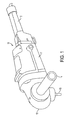
- FIG. 1 illustrates a perspective view of an exemplary rotary power tool on which the present invention may be mounted.
- Figure 1 illustrates a portable electric grinder 10 with which the teachings of the present disclosure may be explained.
- grinder 10 is only exemplary of a wide variety of rotary power tools to which the present teachings may be applied.
- grinder 10 generally comprises a motor housing 11, a switch handle 12, a gear case 13, an auxiliary handle 14, and a right-angle spindle 15 for mounting a grinding wheel assembly 16 (shown best in Figure 4 ) or other tool element assembly.
- Spindle 15 is externally threaded and has an annular shoulder 15A ( Fig. 4 ) formed thereon.
- a tool element assembly, or abrasive disk assembly 16 can be threadably mounted on spindle 15.
- the abrasive disc assembly 16 includes a depressed center surface finishing or abrasive disk 19 that is coupled to an internally threaded hub assembly 17
- Figures 2-4 illustrate abrasive disk assembly 16 of the present invention.
- FIG. 2 illustrates a top perspective view of abrasive disc assembly 16 according to the present invention, which may be used with a rotary surface finishing tool (e.g., a grinder 10).
- Figure 3 shows a bottom view of disk assembly 16.
- hub assembly 17 includes an internally threaded aperture 18 which receives externally threaded spindle 15 of grinder 10.
- Spindle 15 extends through aperture 18 to accommodate a fastener (not shown) with which abrasive disc 16 is fastened to spindle 15. Rotational motion is transmitted from spindle 15 to abrasive disk 19 through hub assembly 17.
- Abrasive disc 19 includes a backing plate 20 that has an aperture 25 that is formed centrally in backing plate 20 for attaching abrasive disc 19 to hub assembly 17. Aperture 25 defines an abrasive disk inner radius.
- Abrasive disc 19 also includes a plurality of abrasive flaps 30, also known as sandpaper flaps. The flaps 30 are generally manufactured from a cloth or paper material and are coated with an abrasive grain or grit. Ordinarily, aluminum oxide grain or a zirconium-aluminium oxide grain is used. This provides the abrasive surface for grinding purposes.
- Each flap 30 is connected to a bottom outer surface of abrasive disk 19 and each overlaps an adjacent flap around the periphery of abrasive disc 19 as shown in Figures 1-4 .
- Rotation of abrasive disc 19 in contact with a work surface causes abrasive flaps 30 to sand or abrasively wear away the work surface.
- backing plate 20 is generally of a circular configuration.
- Backing plate 20 has a desired diameter of about between 100-200mm.
- Ordinarily backing plate 20 also has a desired thickness of about between 3-5mm.
- Backing plate 20 includes abrasive grains 21 applied into the backing material.
- the abrasive grains 21 may be any type of abrasive grains such as the aluminum oxide or zirconium aluminum oxide or others such as blast media.
- the grains 21 are any type of friably or semi-friably sized material.
- a bonding agent generally of phenolic resins, epoxies, phenol epoxies or other organic bonding agents may be utilized to secure the abrasive grains with a woven fiberglass material 23.
- Backing plate 20 is manufactured by laying alternate layers of fiberglass and grinding wheels mixture material 27 upon one another.
- the fiberglass material 23 may be coated with the bonding agent and abrasive grain 21 material. These glass layers (discussed further in figure 6 ) are then pressed under a high pressure tonnage to form a uniform body.
- Backing plate 20 is clamped into shaped plates and cured using a heat process.
- Backing plate 20 has a planar portion 26 within which aperture 25 is defined. Planar portion 26 extends outward from aperture 25 to a stepped portion or offset portion 24. Offset portion 24 is adjacent to and extends away from planar portion 26 toward an annular, planar flange or wearing flange 22. Offset portion 24 is configured to position wearing flange 22 a predetermined radial and axial distance away from spindle 15 of grinder 10.
- Various modifications of the design of backing plate 20 are contemplated within the general scope of the invention. For example, while an offset portion 24 as described above may be utilized, planar portion 26 and wearing flange 22 may lie along substantially the same plane. Those skilled in the art will understand and appreciate the diverse backing plate configurations which may be practiced within the scope of this invention.
- each abrasive flap 30 is attached to wearing flange 22 by means of an adhesive.
- the adhesive is also composed of a material that wears away as it rotationally contacts a work piece.
- Outer surface 34 of flap 30 is positioned at an angle with respect to the plane defined by wearing flange 22.
- Disk performance is directly related to friction generated between the disk and the work piece. This friction is in turn directly related to the amount of force a user applies at grinder 10. In other words, the more force M a user applies to disk 19, the more friction can be generated as the abrasive disk rotates. Application of force M by a user also necessarily generates an internal radial stress profile along backing plate 20.
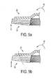
- Figure 5A shows the forces responsible for generating wearing friction that ultimately define a disk's wear profile. A moment force M is applied by a user via grinder 10 with work piece reactionary force R helping to balance the forces involved.
- Figure 5B illustrates an end portion of disk 19 showing a worn away portion of disk 19. The worn away portion is in phantom to define a typical wear profile. Actual wear profiles may vary depending on the loads and angles applied by the user during operation.
- Backing plate 20 is made from a fiber-reinforced resin matrix material which has abrasive particles imbedded therein in the same way as they are in grinding wheels. This mix can be composed so that backing plate material wears away at about the same rate as flaps 30 wear away and so that backing plate 20 does not damage the work piece.
- flap disc 19 has its flaps 30 contact the surface at a desired grind angle ( FIG. 5(c) ) up to a point where wearing flange 22 contacts the surface to be ground ( FIG. 5(d) ).
- Backing plate 20, including the abrasive grains, as well as flaps 30, continue to grind the surface ( FIG. 5(e) ).
- the backing plate 20 and flaps 30 continue to wear during grinding of the surface until flaps 30 are extinguished ( FIG. 5(f) ).
- FIGS. 5(c)-(f) the grind angle of the flap disc 19 remains constant during the entire use of the flaps 30.
- FIGS. 5(g)-(j) are like FIGS. 5(c)-(f) with flap disc 19 at a different grind angle. This is unlike the prior art wherein flap disc 19 must be constantly adjusted in order to compensate for the fact that flaps 30 cannot be used while backing plate 20 contacts the surface.
- Fiber-reinforced resin mix (e.g., a resin mix reinforced with fiberglass) is a solution to at least two backing plate design requirements.
- backing plate 20 must wear with flaps 30.
- backing plate 20 must be sufficiently strong to withstand the internal stresses generated by normal operational loadings (i.e., operator load M). Glass tensile stresses for the disclosed arrangements are typically effective at a strength of at least 2200 Newtons/50 mm. Lower strength glass may be used where external loads will be less.
- the effectiveness of backing plate wear is a function of the placement and proportion of glass and abrasive resin mix in the plate design. While glass is a thin, strong, layered material that is effective in tensile reinforcement, fiberglass can wear less cleanly than the resin mix. In fact, when the mix is disproportionately more highly concentrated with fiberglass, fiberglass strands remain unworn and sometimes melt and burn producing a mess on the work piece and/or an undesirable odor. Resin mix, on the other hand, which includes abrasive particles, grinds away more cleanly. However, in some applications and designs, un-reinforced resin mix can have in sufficient srength (e.g., tensile strength).
- the resin when fiberglass is combined in proper layered proportion to the abrasive particle resin, the resin can interact with the fiberglass to wear the fiberglass more cleanly. Specifically, the rough abrasive characteristics of the resin serve to sever glass fibers more effectively. The result is a strong efficiently wearing backing plate.
- the glass In addition to wearing cleanly, the glass must be arranged in the plate to absorb operating stress.
- the fiberglass portion of backing plate 20 provides strengthening (i.e., tensile strength) to maintain its structural integrity (i.e., so backing plate 20 does not break) during operation.
- reinforcing glass can be positioned in backing plate 20 where stresses (e.g., tensile) are highest. Placement of glass along the thickness of the wheel is most effective in the bottom portion of backing plate 20 since the bottom of the wheel experiences tensile stresses as it is pressed against a work piece.
- glass is positioned in the backing plate within certain radial intervals that experience the highest internal stresses.
- Figure 6A-6 illustrate an enlarged exemplary backing disk 20 on a simplified hub assembly 17.
- the thickness of backing plate 20 is exaggerated to show individual layers (i.e., glass layers (GL 1-6) and two (2) resin mix layers).
- Figure 6B illustrates the general arrangement of the layers showing that certain layers (e.g., fiberglass layers GL2 and GL4) may be truncated relative to the outer diameter of backing plate 20 and relative to other layers (e.g., G1).
- the plate thickness is exaggerated and a space is shown adjacent to the truncated layers. This space does not actually exist.
- the two layers adjacent to the space actually touch and are bonded to each other.
- Figure 6A illustrates the general arrangement of the layers showing an exemplary arrangement of the inner diameter of the layers relative to simplified hub assembly 17.
- the result of the foregoing structure is that the radial positioning of reinforcing material within reinforcing layers is non-uniform so that reinforcing material in at least one layer is radially located in a position where no reinforcing material is found in another layer. Furthermore, even if the reinforcing structure is not specifically a layered structure, it can be said that the radial positioning of reinforcing material is non-uniform along the thickness (i.e., from the bottom of the backing plate 20 where flaps 30 are connected to the opposite side) of the backing plate. This means that reinforcing material extends within some radial interval at one thickness, while at another thickness, no reinforcing material exists within that same radial interval.
- FIG. 6 A variety of layer arrangements may be utilized. However, the general arrangement shown in Figure 6 provides significant glass tensile reinforcement on the bottom toward GL 6 while providing upper resin mix layers that serve to sever undesirable GL 5 and GL6 strands. Glass layer GL 4 is truncated and will not extend to the wearing flange 22. Therefore, the illustrated arrangement allows the abrasive disk 19 to wear effectively, and at the same time, provides for a sufficiently strong abrasive disk that a user can apply significant force to the disk 19 for effective grinding.
- the present invention also contemplates a backing plate that includes strands of varying strength, positioned in various positions about the plate.
Landscapes
- Engineering & Computer Science (AREA)
- Mechanical Engineering (AREA)
- Polishing Bodies And Polishing Tools (AREA)
Applications Claiming Priority (1)
| Application Number | Priority Date | Filing Date | Title |
|---|---|---|---|
| US12/887,857 US8585470B2 (en) | 2010-09-22 | 2010-09-22 | Wearable backing for an abrasive flap disk |
Publications (3)
| Publication Number | Publication Date |
|---|---|
| EP2433748A2 true EP2433748A2 (de) | 2012-03-28 |
| EP2433748A3 EP2433748A3 (de) | 2015-04-29 |
| EP2433748B1 EP2433748B1 (de) | 2016-06-01 |
Family
ID=44785375
Family Applications (1)
| Application Number | Title | Priority Date | Filing Date |
|---|---|---|---|
| EP11181262.4A Active EP2433748B1 (de) | 2010-09-22 | 2011-09-14 | Tragbare Verstärkung für eine abrasive Lamellenscheibe |
Country Status (3)
| Country | Link |
|---|---|
| US (1) | US8585470B2 (de) |
| EP (1) | EP2433748B1 (de) |
| CN (1) | CN202428342U (de) |
Cited By (3)
| Publication number | Priority date | Publication date | Assignee | Title |
|---|---|---|---|---|
| EP3015222A1 (de) * | 2015-07-09 | 2016-05-04 | Lukas-Erzett Vereinigte Schleif- und Fräswerkzeugfabriken GmbH & Co. KG | Schleifscheibe |
| EP3173190A1 (de) | 2015-11-27 | 2017-05-31 | Przedsiebiorstwo Pentar Stanislaw Róg | Abrasive lamellenscheibe |
| WO2018036616A1 (de) * | 2016-08-23 | 2018-03-01 | August Rüggeberg Gmbh & Co. Kg | Schrupp-schleifwerkzeug |
Families Citing this family (10)
| Publication number | Priority date | Publication date | Assignee | Title |
|---|---|---|---|---|
| DE102010046878B3 (de) * | 2010-09-29 | 2011-12-15 | Dipl.-Ing. Günter Wendt GmbH | Lamellenschleifwerkzeug |
| JP6529210B2 (ja) | 2013-04-04 | 2019-06-12 | スリーエム イノベイティブ プロパティズ カンパニー | 研磨ディスクを用いる研磨方法およびこれに用いる物品 |
| CN105658376B (zh) * | 2013-10-25 | 2020-05-26 | 依视路国际公司 | 光学品质表面修整工具 |
| US20150283675A1 (en) * | 2014-04-04 | 2015-10-08 | Campana Mirco E Figli S.N.C. | Disc for power tools for supporting abrasive material and abrasive disc comprising said support |
| US11273535B2 (en) * | 2015-08-21 | 2022-03-15 | Pferd Milwaukee Brush Company, Inc. | Abrasive tool and method for producing an abrasive tool of this kind |
| WO2018093629A1 (en) * | 2016-11-15 | 2018-05-24 | Saint-Gobain Abrasives, Inc. | Abrasive flap disc including wearable backing plate |
| CA3054036A1 (en) * | 2018-12-28 | 2020-06-28 | Virtual Machines Inc. | Method and system for producing abrasive products |
| DE102020207733A1 (de) * | 2019-09-04 | 2021-03-04 | Robert Bosch Gesellschaft mit beschränkter Haftung | Schleifwerkzeugvorrichtung, Schleifmittel und Schleifwerkzeugsystem |
| DE202019005658U1 (de) | 2019-10-25 | 2021-07-12 | Marius Claassen | Trägerplatte sowie Lamellenschleifscheibe umfassend diese Trägerplatte |
| KR102296729B1 (ko) * | 2021-06-03 | 2021-08-31 | 빈인선 | 밀착 효율이 높은 전동연마기 탈부착용 연마디스크 |
Citations (2)
| Publication number | Priority date | Publication date | Assignee | Title |
|---|---|---|---|---|
| US5752876A (en) | 1995-10-23 | 1998-05-19 | Weiler Brush Company, Inc. | Flap disc abrasive tool |
| US6945863B1 (en) | 2004-08-19 | 2005-09-20 | Weiler Corporation | Rotary finishing disc |
Family Cites Families (8)
| Publication number | Priority date | Publication date | Assignee | Title |
|---|---|---|---|---|
| GB536970A (en) * | 1939-09-12 | 1941-06-04 | Black & Decker Mfg Co | Improvements in or relating to flexible abrasive pads |
| DE3741279A1 (de) | 1987-12-05 | 1989-06-15 | Jochen C Dzierzon | Schleifscheibe |
| US5431596A (en) * | 1993-04-28 | 1995-07-11 | Akita; Hiroshi | Grinding wheel and a method for manufacturing the same |
| US5951389A (en) * | 1995-10-23 | 1999-09-14 | Weiler Corporation | Drive system for small diameter abrasive discs |
| DE10042109C2 (de) * | 2000-08-28 | 2003-07-03 | M & F Entw & Patentverwertungs | Polierwerkzeug |
| DE10106631A1 (de) * | 2001-02-12 | 2002-08-22 | Rueggeberg August Gmbh & Co | Tragteller für Fächerschleifscheibe und Fächerschleifscheibe |
| US6863596B2 (en) * | 2001-05-25 | 2005-03-08 | 3M Innovative Properties Company | Abrasive article |
| US8246425B2 (en) * | 2010-01-15 | 2012-08-21 | J. Walter Company Ltd. | Abrasive wheel comprising a fan-like structure |
-
2010
- 2010-09-22 US US12/887,857 patent/US8585470B2/en not_active Expired - Fee Related
-
2011
- 2011-09-14 EP EP11181262.4A patent/EP2433748B1/de active Active
- 2011-09-22 CN CN2011204900913U patent/CN202428342U/zh not_active Expired - Fee Related
Patent Citations (2)
| Publication number | Priority date | Publication date | Assignee | Title |
|---|---|---|---|---|
| US5752876A (en) | 1995-10-23 | 1998-05-19 | Weiler Brush Company, Inc. | Flap disc abrasive tool |
| US6945863B1 (en) | 2004-08-19 | 2005-09-20 | Weiler Corporation | Rotary finishing disc |
Cited By (11)
| Publication number | Priority date | Publication date | Assignee | Title |
|---|---|---|---|---|
| EP3015222A1 (de) * | 2015-07-09 | 2016-05-04 | Lukas-Erzett Vereinigte Schleif- und Fräswerkzeugfabriken GmbH & Co. KG | Schleifscheibe |
| WO2017005569A1 (de) * | 2015-07-09 | 2017-01-12 | Lukas-Erzett Vereinigte Schleif- Und Fräswerkzeugfabriken Gmbh & Co. Kg | Schleifscheibe |
| US10500698B2 (en) | 2015-07-09 | 2019-12-10 | Lukas-Erzett Vereinigte Schlief-und Fraswerkzeugfabriken GmbH & Co KG | Grinding disc |
| EP3173190A1 (de) | 2015-11-27 | 2017-05-31 | Przedsiebiorstwo Pentar Stanislaw Róg | Abrasive lamellenscheibe |
| WO2017091093A1 (en) | 2015-11-27 | 2017-06-01 | Przedsiębiorstwo Pentar Stanisław Róg | Abrasive flap disc |
| US10933510B2 (en) | 2015-11-27 | 2021-03-02 | Przedsiebiorstwo Pentar Stanislaw Rog | Abrasive flap disc |
| WO2018036616A1 (de) * | 2016-08-23 | 2018-03-01 | August Rüggeberg Gmbh & Co. Kg | Schrupp-schleifwerkzeug |
| RU2721972C1 (ru) * | 2016-08-23 | 2020-05-25 | Август Рюггеберг Гмбх & Ко. Кг | Инструмент для грубого шлифования |
| RU2721972C9 (ru) * | 2016-08-23 | 2020-07-29 | Август Рюггеберг Гмбх & Ко. Кг | Инструмент для грубого шлифования |
| TWI749040B (zh) * | 2016-08-23 | 2021-12-11 | 德商八月魯吉堡股份有限公司 | 粗磨工具 |
| AU2016421095B2 (en) * | 2016-08-23 | 2022-03-31 | August Rüggeberg Gmbh & Co. Kg | Roughing grinding tool |
Also Published As
| Publication number | Publication date |
|---|---|
| US8585470B2 (en) | 2013-11-19 |
| EP2433748A3 (de) | 2015-04-29 |
| US20120071073A1 (en) | 2012-03-22 |
| CN202428342U (zh) | 2012-09-12 |
| EP2433748B1 (de) | 2016-06-01 |
Similar Documents
| Publication | Publication Date | Title |
|---|---|---|
| EP2433748B1 (de) | Tragbare Verstärkung für eine abrasive Lamellenscheibe | |
| EP1463608B1 (de) | Schleifscheiben mit werkstücksichtmerkmal | |
| KR100451686B1 (ko) | 보강 연마휠 | |
| CN105189044B (zh) | 用于支撑研磨盘的衬垫 | |
| US4715150A (en) | Nonwoven fiber abrasive disk | |
| AU2002216693A1 (en) | Abrasive wheels with workpiece vision feature | |
| US6066034A (en) | V-shaped flap disc abrasive tool | |
| CN106457520B (zh) | 一种纤维板研磨工具 | |
| CN102935620A (zh) | 带有一体化安装板的盘式磨轮 | |
| JPS60114470A (ja) | 回転研削研磨具 | |
| US20140045414A1 (en) | Surface machining tool | |
| US20220080555A1 (en) | Bilateral abrasive disc pad | |
| EP1082195B1 (de) | Schneidescheibe mit schwingungsdämpfender folie | |
| KR102241377B1 (ko) | 단위 구조를 갖는 조립식 그라인더 휠 | |
| JP2004050355A (ja) | 積層型回転研磨具及びその使用方法 | |
| JP4381520B2 (ja) | 研削面観察用透視孔が開けられたオフセット型フレキシブル砥石 | |
| JP7633408B2 (ja) | 回転工具 | |
| US20230211465A1 (en) | Abrasive for the production of a grinding tool, grinding tool and method for operating a grinding tool of this type | |
| WO2012052090A1 (de) | Lamellenschleifwerkzeug | |
| JP5307686B2 (ja) | 回転砥石 | |
| JP2004338022A (ja) | ディスク砥石およびその製造方法 | |
| JP6858730B2 (ja) | 略ディスク形状を有する研磨部材の製造方法および研磨部材 | |
| JPH08132348A (ja) | 曲面加工用研摩工具 | |
| JP2014108475A (ja) | バックアップパッド付き研磨ディスク | |
| MXPA01006177A (en) | Grinding disc with backup pad |
Legal Events
| Date | Code | Title | Description |
|---|---|---|---|
| PUAI | Public reference made under article 153(3) epc to a published international application that has entered the european phase |
Free format text: ORIGINAL CODE: 0009012 |
|
| AK | Designated contracting states |
Kind code of ref document: A2 Designated state(s): AL AT BE BG CH CY CZ DE DK EE ES FI FR GB GR HR HU IE IS IT LI LT LU LV MC MK MT NL NO PL PT RO RS SE SI SK SM TR |
|
| AX | Request for extension of the european patent |
Extension state: BA ME |
|
| PUAL | Search report despatched |
Free format text: ORIGINAL CODE: 0009013 |
|
| AK | Designated contracting states |
Kind code of ref document: A3 Designated state(s): AL AT BE BG CH CY CZ DE DK EE ES FI FR GB GR HR HU IE IS IT LI LT LU LV MC MK MT NL NO PL PT RO RS SE SI SK SM TR |
|
| AX | Request for extension of the european patent |
Extension state: BA ME |
|
| RIC1 | Information provided on ipc code assigned before grant |
Ipc: B24D 13/16 20060101ALI20150320BHEP Ipc: B24B 23/02 20060101AFI20150320BHEP |
|
| 17P | Request for examination filed |
Effective date: 20150608 |
|
| RBV | Designated contracting states (corrected) |
Designated state(s): AL AT BE BG CH CY CZ DE DK EE ES FI FR GB GR HR HU IE IS IT LI LT LU LV MC MK MT NL NO PL PT RO RS SE SI SK SM TR |
|
| GRAP | Despatch of communication of intention to grant a patent |
Free format text: ORIGINAL CODE: EPIDOSNIGR1 |
|
| INTG | Intention to grant announced |
Effective date: 20160212 |
|
| GRAS | Grant fee paid |
Free format text: ORIGINAL CODE: EPIDOSNIGR3 |
|
| GRAA | (expected) grant |
Free format text: ORIGINAL CODE: 0009210 |
|
| AK | Designated contracting states |
Kind code of ref document: B1 Designated state(s): AL AT BE BG CH CY CZ DE DK EE ES FI FR GB GR HR HU IE IS IT LI LT LU LV MC MK MT NL NO PL PT RO RS SE SI SK SM TR |
|
| REG | Reference to a national code |
Ref country code: GB Ref legal event code: FG4D |
|
| REG | Reference to a national code |
Ref country code: CH Ref legal event code: EP Ref country code: AT Ref legal event code: REF Ref document number: 803575 Country of ref document: AT Kind code of ref document: T Effective date: 20160615 |
|
| REG | Reference to a national code |
Ref country code: IE Ref legal event code: FG4D |
|
| REG | Reference to a national code |
Ref country code: DE Ref legal event code: R096 Ref document number: 602011027059 Country of ref document: DE |
|
| REG | Reference to a national code |
Ref country code: LT Ref legal event code: MG4D |
|
| REG | Reference to a national code |
Ref country code: NL Ref legal event code: MP Effective date: 20160601 |
|
| PG25 | Lapsed in a contracting state [announced via postgrant information from national office to epo] |
Ref country code: FI Free format text: LAPSE BECAUSE OF FAILURE TO SUBMIT A TRANSLATION OF THE DESCRIPTION OR TO PAY THE FEE WITHIN THE PRESCRIBED TIME-LIMIT Effective date: 20160601 Ref country code: LT Free format text: LAPSE BECAUSE OF FAILURE TO SUBMIT A TRANSLATION OF THE DESCRIPTION OR TO PAY THE FEE WITHIN THE PRESCRIBED TIME-LIMIT Effective date: 20160601 Ref country code: NO Free format text: LAPSE BECAUSE OF FAILURE TO SUBMIT A TRANSLATION OF THE DESCRIPTION OR TO PAY THE FEE WITHIN THE PRESCRIBED TIME-LIMIT Effective date: 20160901 |
|
| REG | Reference to a national code |
Ref country code: AT Ref legal event code: MK05 Ref document number: 803575 Country of ref document: AT Kind code of ref document: T Effective date: 20160601 |
|
| PG25 | Lapsed in a contracting state [announced via postgrant information from national office to epo] |
Ref country code: RS Free format text: LAPSE BECAUSE OF FAILURE TO SUBMIT A TRANSLATION OF THE DESCRIPTION OR TO PAY THE FEE WITHIN THE PRESCRIBED TIME-LIMIT Effective date: 20160601 Ref country code: ES Free format text: LAPSE BECAUSE OF FAILURE TO SUBMIT A TRANSLATION OF THE DESCRIPTION OR TO PAY THE FEE WITHIN THE PRESCRIBED TIME-LIMIT Effective date: 20160601 Ref country code: NL Free format text: LAPSE BECAUSE OF FAILURE TO SUBMIT A TRANSLATION OF THE DESCRIPTION OR TO PAY THE FEE WITHIN THE PRESCRIBED TIME-LIMIT Effective date: 20160601 Ref country code: GR Free format text: LAPSE BECAUSE OF FAILURE TO SUBMIT A TRANSLATION OF THE DESCRIPTION OR TO PAY THE FEE WITHIN THE PRESCRIBED TIME-LIMIT Effective date: 20160902 Ref country code: LV Free format text: LAPSE BECAUSE OF FAILURE TO SUBMIT A TRANSLATION OF THE DESCRIPTION OR TO PAY THE FEE WITHIN THE PRESCRIBED TIME-LIMIT Effective date: 20160601 Ref country code: SE Free format text: LAPSE BECAUSE OF FAILURE TO SUBMIT A TRANSLATION OF THE DESCRIPTION OR TO PAY THE FEE WITHIN THE PRESCRIBED TIME-LIMIT Effective date: 20160601 |
|
| PG25 | Lapsed in a contracting state [announced via postgrant information from national office to epo] |
Ref country code: IT Free format text: LAPSE BECAUSE OF FAILURE TO SUBMIT A TRANSLATION OF THE DESCRIPTION OR TO PAY THE FEE WITHIN THE PRESCRIBED TIME-LIMIT Effective date: 20160601 Ref country code: EE Free format text: LAPSE BECAUSE OF FAILURE TO SUBMIT A TRANSLATION OF THE DESCRIPTION OR TO PAY THE FEE WITHIN THE PRESCRIBED TIME-LIMIT Effective date: 20160601 Ref country code: SK Free format text: LAPSE BECAUSE OF FAILURE TO SUBMIT A TRANSLATION OF THE DESCRIPTION OR TO PAY THE FEE WITHIN THE PRESCRIBED TIME-LIMIT Effective date: 20160601 Ref country code: RO Free format text: LAPSE BECAUSE OF FAILURE TO SUBMIT A TRANSLATION OF THE DESCRIPTION OR TO PAY THE FEE WITHIN THE PRESCRIBED TIME-LIMIT Effective date: 20160601 Ref country code: CZ Free format text: LAPSE BECAUSE OF FAILURE TO SUBMIT A TRANSLATION OF THE DESCRIPTION OR TO PAY THE FEE WITHIN THE PRESCRIBED TIME-LIMIT Effective date: 20160601 Ref country code: IS Free format text: LAPSE BECAUSE OF FAILURE TO SUBMIT A TRANSLATION OF THE DESCRIPTION OR TO PAY THE FEE WITHIN THE PRESCRIBED TIME-LIMIT Effective date: 20161001 |
|
| PG25 | Lapsed in a contracting state [announced via postgrant information from national office to epo] |
Ref country code: SM Free format text: LAPSE BECAUSE OF FAILURE TO SUBMIT A TRANSLATION OF THE DESCRIPTION OR TO PAY THE FEE WITHIN THE PRESCRIBED TIME-LIMIT Effective date: 20160601 Ref country code: PT Free format text: LAPSE BECAUSE OF FAILURE TO SUBMIT A TRANSLATION OF THE DESCRIPTION OR TO PAY THE FEE WITHIN THE PRESCRIBED TIME-LIMIT Effective date: 20161003 Ref country code: PL Free format text: LAPSE BECAUSE OF FAILURE TO SUBMIT A TRANSLATION OF THE DESCRIPTION OR TO PAY THE FEE WITHIN THE PRESCRIBED TIME-LIMIT Effective date: 20160601 Ref country code: AT Free format text: LAPSE BECAUSE OF FAILURE TO SUBMIT A TRANSLATION OF THE DESCRIPTION OR TO PAY THE FEE WITHIN THE PRESCRIBED TIME-LIMIT Effective date: 20160601 Ref country code: BE Free format text: LAPSE BECAUSE OF NON-PAYMENT OF DUE FEES Effective date: 20160601 |
|
| REG | Reference to a national code |
Ref country code: DE Ref legal event code: R097 Ref document number: 602011027059 Country of ref document: DE |
|
| PLBE | No opposition filed within time limit |
Free format text: ORIGINAL CODE: 0009261 |
|
| STAA | Information on the status of an ep patent application or granted ep patent |
Free format text: STATUS: NO OPPOSITION FILED WITHIN TIME LIMIT |
|
| PG25 | Lapsed in a contracting state [announced via postgrant information from national office to epo] |
Ref country code: MC Free format text: LAPSE BECAUSE OF FAILURE TO SUBMIT A TRANSLATION OF THE DESCRIPTION OR TO PAY THE FEE WITHIN THE PRESCRIBED TIME-LIMIT Effective date: 20160601 |
|
| REG | Reference to a national code |
Ref country code: CH Ref legal event code: PL |
|
| 26N | No opposition filed |
Effective date: 20170302 |
|
| PG25 | Lapsed in a contracting state [announced via postgrant information from national office to epo] |
Ref country code: SI Free format text: LAPSE BECAUSE OF FAILURE TO SUBMIT A TRANSLATION OF THE DESCRIPTION OR TO PAY THE FEE WITHIN THE PRESCRIBED TIME-LIMIT Effective date: 20160601 Ref country code: DK Free format text: LAPSE BECAUSE OF FAILURE TO SUBMIT A TRANSLATION OF THE DESCRIPTION OR TO PAY THE FEE WITHIN THE PRESCRIBED TIME-LIMIT Effective date: 20160601 |
|
| REG | Reference to a national code |
Ref country code: IE Ref legal event code: MM4A |
|
| REG | Reference to a national code |
Ref country code: FR Ref legal event code: ST Effective date: 20170531 |
|
| PG25 | Lapsed in a contracting state [announced via postgrant information from national office to epo] |
Ref country code: FR Free format text: LAPSE BECAUSE OF NON-PAYMENT OF DUE FEES Effective date: 20160930 Ref country code: IE Free format text: LAPSE BECAUSE OF NON-PAYMENT OF DUE FEES Effective date: 20160914 Ref country code: LI Free format text: LAPSE BECAUSE OF NON-PAYMENT OF DUE FEES Effective date: 20160930 Ref country code: CH Free format text: LAPSE BECAUSE OF NON-PAYMENT OF DUE FEES Effective date: 20160930 |
|
| PG25 | Lapsed in a contracting state [announced via postgrant information from national office to epo] |
Ref country code: LU Free format text: LAPSE BECAUSE OF NON-PAYMENT OF DUE FEES Effective date: 20160914 |
|
| PG25 | Lapsed in a contracting state [announced via postgrant information from national office to epo] |
Ref country code: HU Free format text: LAPSE BECAUSE OF FAILURE TO SUBMIT A TRANSLATION OF THE DESCRIPTION OR TO PAY THE FEE WITHIN THE PRESCRIBED TIME-LIMIT; INVALID AB INITIO Effective date: 20110914 Ref country code: CY Free format text: LAPSE BECAUSE OF FAILURE TO SUBMIT A TRANSLATION OF THE DESCRIPTION OR TO PAY THE FEE WITHIN THE PRESCRIBED TIME-LIMIT Effective date: 20160601 |
|
| PG25 | Lapsed in a contracting state [announced via postgrant information from national office to epo] |
Ref country code: HR Free format text: LAPSE BECAUSE OF FAILURE TO SUBMIT A TRANSLATION OF THE DESCRIPTION OR TO PAY THE FEE WITHIN THE PRESCRIBED TIME-LIMIT Effective date: 20160601 Ref country code: MK Free format text: LAPSE BECAUSE OF FAILURE TO SUBMIT A TRANSLATION OF THE DESCRIPTION OR TO PAY THE FEE WITHIN THE PRESCRIBED TIME-LIMIT Effective date: 20160601 Ref country code: MT Free format text: LAPSE BECAUSE OF NON-PAYMENT OF DUE FEES Effective date: 20160930 Ref country code: TR Free format text: LAPSE BECAUSE OF FAILURE TO SUBMIT A TRANSLATION OF THE DESCRIPTION OR TO PAY THE FEE WITHIN THE PRESCRIBED TIME-LIMIT Effective date: 20160601 |
|
| PG25 | Lapsed in a contracting state [announced via postgrant information from national office to epo] |
Ref country code: BG Free format text: LAPSE BECAUSE OF FAILURE TO SUBMIT A TRANSLATION OF THE DESCRIPTION OR TO PAY THE FEE WITHIN THE PRESCRIBED TIME-LIMIT Effective date: 20160601 |
|
| PG25 | Lapsed in a contracting state [announced via postgrant information from national office to epo] |
Ref country code: AL Free format text: LAPSE BECAUSE OF FAILURE TO SUBMIT A TRANSLATION OF THE DESCRIPTION OR TO PAY THE FEE WITHIN THE PRESCRIBED TIME-LIMIT Effective date: 20160601 |
|
| PGFP | Annual fee paid to national office [announced via postgrant information from national office to epo] |
Ref country code: DE Payment date: 20250919 Year of fee payment: 15 |
|
| PGFP | Annual fee paid to national office [announced via postgrant information from national office to epo] |
Ref country code: GB Payment date: 20250923 Year of fee payment: 15 |