EP2433662A1 - Appareil pour le traitement extracorporel du sang - Google Patents
Appareil pour le traitement extracorporel du sang Download PDFInfo
- Publication number
- EP2433662A1 EP2433662A1 EP10010805A EP10010805A EP2433662A1 EP 2433662 A1 EP2433662 A1 EP 2433662A1 EP 10010805 A EP10010805 A EP 10010805A EP 10010805 A EP10010805 A EP 10010805A EP 2433662 A1 EP2433662 A1 EP 2433662A1
- Authority
- EP
- European Patent Office
- Prior art keywords
- dose
- fluid
- flow rate
- value
- blood
- Prior art date
- Legal status (The legal status is an assumption and is not a legal conclusion. Google has not performed a legal analysis and makes no representation as to the accuracy of the status listed.)
- Granted
Links
- 210000004369 blood Anatomy 0.000 title claims abstract description 150
- 239000008280 blood Substances 0.000 title claims abstract description 150
- 238000011282 treatment Methods 0.000 title claims abstract description 148
- 239000012530 fluid Substances 0.000 claims abstract description 188
- 238000010790 dilution Methods 0.000 claims abstract description 85
- 239000012895 dilution Substances 0.000 claims abstract description 85
- 238000000034 method Methods 0.000 claims abstract description 83
- 230000001105 regulatory effect Effects 0.000 claims abstract description 52
- 239000000385 dialysis solution Substances 0.000 claims abstract description 35
- 238000001914 filtration Methods 0.000 claims abstract description 20
- 238000001802 infusion Methods 0.000 claims description 66
- 239000003978 infusion fluid Substances 0.000 claims description 36
- 239000004202 carbamide Substances 0.000 claims description 27
- 238000000502 dialysis Methods 0.000 claims description 27
- 230000001276 controlling effect Effects 0.000 claims description 26
- XSQUKJJJFZCRTK-UHFFFAOYSA-N Urea Chemical compound NC(N)=O XSQUKJJJFZCRTK-UHFFFAOYSA-N 0.000 claims description 24
- 239000012528 membrane Substances 0.000 claims description 16
- 239000007788 liquid Substances 0.000 claims description 14
- 238000011144 upstream manufacturing Methods 0.000 claims description 7
- 210000000748 cardiovascular system Anatomy 0.000 claims description 3
- 238000002615 hemofiltration Methods 0.000 description 18
- 239000000243 solution Substances 0.000 description 15
- 238000001631 haemodialysis Methods 0.000 description 12
- 230000000322 hemodialysis Effects 0.000 description 12
- 238000000108 ultra-filtration Methods 0.000 description 10
- 230000017531 blood circulation Effects 0.000 description 8
- 238000004364 calculation method Methods 0.000 description 8
- 230000001154 acute effect Effects 0.000 description 7
- 230000037396 body weight Effects 0.000 description 6
- 230000006870 function Effects 0.000 description 5
- 0 CC*CC(C)C(CC*=*C1CCCC1)=C Chemical compound CC*CC(C)C(CC*=*C1CCCC1)=C 0.000 description 4
- KRKNYBCHXYNGOX-UHFFFAOYSA-K Citrate Chemical compound [O-]C(=O)CC(O)(CC([O-])=O)C([O-])=O KRKNYBCHXYNGOX-UHFFFAOYSA-K 0.000 description 4
- 230000001419 dependent effect Effects 0.000 description 4
- 238000010586 diagram Methods 0.000 description 4
- 210000003743 erythrocyte Anatomy 0.000 description 4
- 230000015654 memory Effects 0.000 description 4
- 230000002572 peristaltic effect Effects 0.000 description 4
- 239000002699 waste material Substances 0.000 description 4
- XLYOFNOQVPJJNP-UHFFFAOYSA-N water Substances O XLYOFNOQVPJJNP-UHFFFAOYSA-N 0.000 description 4
- 208000001647 Renal Insufficiency Diseases 0.000 description 3
- 239000003146 anticoagulant agent Substances 0.000 description 3
- 229940127219 anticoagulant drug Drugs 0.000 description 3
- 238000012937 correction Methods 0.000 description 3
- 238000007619 statistical method Methods 0.000 description 3
- 238000002560 therapeutic procedure Methods 0.000 description 3
- 238000012546 transfer Methods 0.000 description 3
- 238000004422 calculation algorithm Methods 0.000 description 2
- 238000013461 design Methods 0.000 description 2
- 239000003814 drug Substances 0.000 description 2
- 229940079593 drug Drugs 0.000 description 2
- 230000000694 effects Effects 0.000 description 2
- 201000006370 kidney failure Diseases 0.000 description 2
- 230000002792 vascular Effects 0.000 description 2
- DGAQECJNVWCQMB-PUAWFVPOSA-M Ilexoside XXIX Chemical compound C[C@@H]1CC[C@@]2(CC[C@@]3(C(=CC[C@H]4[C@]3(CC[C@@H]5[C@@]4(CC[C@@H](C5(C)C)OS(=O)(=O)[O-])C)C)[C@@H]2[C@]1(C)O)C)C(=O)O[C@H]6[C@@H]([C@H]([C@@H]([C@H](O6)CO)O)O)O.[Na+] DGAQECJNVWCQMB-PUAWFVPOSA-M 0.000 description 1
- 239000002253 acid Substances 0.000 description 1
- 230000010100 anticoagulation Effects 0.000 description 1
- 239000012223 aqueous fraction Substances 0.000 description 1
- 210000001124 body fluid Anatomy 0.000 description 1
- 239000010839 body fluid Substances 0.000 description 1
- 238000004891 communication Methods 0.000 description 1
- 230000001955 cumulated effect Effects 0.000 description 1
- 238000009792 diffusion process Methods 0.000 description 1
- 238000002637 fluid replacement therapy Methods 0.000 description 1
- 238000005534 hematocrit Methods 0.000 description 1
- 230000002045 lasting effect Effects 0.000 description 1
- 238000007726 management method Methods 0.000 description 1
- 230000005055 memory storage Effects 0.000 description 1
- 238000012544 monitoring process Methods 0.000 description 1
- 238000011328 necessary treatment Methods 0.000 description 1
- 235000015097 nutrients Nutrition 0.000 description 1
- 230000003287 optical effect Effects 0.000 description 1
- 230000000737 periodic effect Effects 0.000 description 1
- 102000004169 proteins and genes Human genes 0.000 description 1
- 108090000623 proteins and genes Proteins 0.000 description 1
- 229910052708 sodium Inorganic materials 0.000 description 1
- 239000011734 sodium Substances 0.000 description 1
- 239000000126 substance Substances 0.000 description 1
- 238000006467 substitution reaction Methods 0.000 description 1
- 230000001960 triggered effect Effects 0.000 description 1
Images


Classifications
-
- A—HUMAN NECESSITIES
- A61—MEDICAL OR VETERINARY SCIENCE; HYGIENE
- A61M—DEVICES FOR INTRODUCING MEDIA INTO, OR ONTO, THE BODY; DEVICES FOR TRANSDUCING BODY MEDIA OR FOR TAKING MEDIA FROM THE BODY; DEVICES FOR PRODUCING OR ENDING SLEEP OR STUPOR
- A61M1/00—Suction or pumping devices for medical purposes; Devices for carrying-off, for treatment of, or for carrying-over, body-liquids; Drainage systems
- A61M1/36—Other treatment of blood in a by-pass of the natural circulatory system, e.g. temperature adaptation, irradiation ; Extra-corporeal blood circuits
- A61M1/3621—Extra-corporeal blood circuits
- A61M1/3663—Flow rate transducers; Flow integrators
-
- A—HUMAN NECESSITIES
- A61—MEDICAL OR VETERINARY SCIENCE; HYGIENE
- A61M—DEVICES FOR INTRODUCING MEDIA INTO, OR ONTO, THE BODY; DEVICES FOR TRANSDUCING BODY MEDIA OR FOR TAKING MEDIA FROM THE BODY; DEVICES FOR PRODUCING OR ENDING SLEEP OR STUPOR
- A61M1/00—Suction or pumping devices for medical purposes; Devices for carrying-off, for treatment of, or for carrying-over, body-liquids; Drainage systems
- A61M1/14—Dialysis systems; Artificial kidneys; Blood oxygenators ; Reciprocating systems for treatment of body fluids, e.g. single needle systems for hemofiltration or pheresis
- A61M1/16—Dialysis systems; Artificial kidneys; Blood oxygenators ; Reciprocating systems for treatment of body fluids, e.g. single needle systems for hemofiltration or pheresis with membranes
- A61M1/1601—Control or regulation
-
- A—HUMAN NECESSITIES
- A61—MEDICAL OR VETERINARY SCIENCE; HYGIENE
- A61M—DEVICES FOR INTRODUCING MEDIA INTO, OR ONTO, THE BODY; DEVICES FOR TRANSDUCING BODY MEDIA OR FOR TAKING MEDIA FROM THE BODY; DEVICES FOR PRODUCING OR ENDING SLEEP OR STUPOR
- A61M1/00—Suction or pumping devices for medical purposes; Devices for carrying-off, for treatment of, or for carrying-over, body-liquids; Drainage systems
- A61M1/14—Dialysis systems; Artificial kidneys; Blood oxygenators ; Reciprocating systems for treatment of body fluids, e.g. single needle systems for hemofiltration or pheresis
- A61M1/16—Dialysis systems; Artificial kidneys; Blood oxygenators ; Reciprocating systems for treatment of body fluids, e.g. single needle systems for hemofiltration or pheresis with membranes
- A61M1/1621—Constructional aspects thereof
- A61M1/1643—Constructional aspects thereof with weighing of fresh and used dialysis fluid
-
- A—HUMAN NECESSITIES
- A61—MEDICAL OR VETERINARY SCIENCE; HYGIENE
- A61M—DEVICES FOR INTRODUCING MEDIA INTO, OR ONTO, THE BODY; DEVICES FOR TRANSDUCING BODY MEDIA OR FOR TAKING MEDIA FROM THE BODY; DEVICES FOR PRODUCING OR ENDING SLEEP OR STUPOR
- A61M1/00—Suction or pumping devices for medical purposes; Devices for carrying-off, for treatment of, or for carrying-over, body-liquids; Drainage systems
- A61M1/34—Filtering material out of the blood by passing it through a membrane, i.e. hemofiltration or diafiltration
- A61M1/342—Adding solutions to the blood, e.g. substitution solutions
- A61M1/3424—Substitution fluid path
- A61M1/3431—Substitution fluid path upstream of the filter
- A61M1/3434—Substitution fluid path upstream of the filter with pre-dilution and post-dilution
-
- A—HUMAN NECESSITIES
- A61—MEDICAL OR VETERINARY SCIENCE; HYGIENE
- A61M—DEVICES FOR INTRODUCING MEDIA INTO, OR ONTO, THE BODY; DEVICES FOR TRANSDUCING BODY MEDIA OR FOR TAKING MEDIA FROM THE BODY; DEVICES FOR PRODUCING OR ENDING SLEEP OR STUPOR
- A61M1/00—Suction or pumping devices for medical purposes; Devices for carrying-off, for treatment of, or for carrying-over, body-liquids; Drainage systems
- A61M1/34—Filtering material out of the blood by passing it through a membrane, i.e. hemofiltration or diafiltration
- A61M1/342—Adding solutions to the blood, e.g. substitution solutions
- A61M1/3424—Substitution fluid path
- A61M1/3437—Substitution fluid path downstream of the filter, e.g. post-dilution with filtrate
-
- A—HUMAN NECESSITIES
- A61—MEDICAL OR VETERINARY SCIENCE; HYGIENE
- A61M—DEVICES FOR INTRODUCING MEDIA INTO, OR ONTO, THE BODY; DEVICES FOR TRANSDUCING BODY MEDIA OR FOR TAKING MEDIA FROM THE BODY; DEVICES FOR PRODUCING OR ENDING SLEEP OR STUPOR
- A61M1/00—Suction or pumping devices for medical purposes; Devices for carrying-off, for treatment of, or for carrying-over, body-liquids; Drainage systems
- A61M1/34—Filtering material out of the blood by passing it through a membrane, i.e. hemofiltration or diafiltration
- A61M1/342—Adding solutions to the blood, e.g. substitution solutions
- A61M1/3441—Substitution rate control as a function of the ultrafiltration rate
- A61M1/3451—Substitution rate control as a function of the ultrafiltration rate the difference in weight between both ultra-filtrate and substitution reservoir being used as control signal
-
- A—HUMAN NECESSITIES
- A61—MEDICAL OR VETERINARY SCIENCE; HYGIENE
- A61M—DEVICES FOR INTRODUCING MEDIA INTO, OR ONTO, THE BODY; DEVICES FOR TRANSDUCING BODY MEDIA OR FOR TAKING MEDIA FROM THE BODY; DEVICES FOR PRODUCING OR ENDING SLEEP OR STUPOR
- A61M2205/00—General characteristics of the apparatus
- A61M2205/33—Controlling, regulating or measuring
- A61M2205/3331—Pressure; Flow
- A61M2205/3334—Measuring or controlling the flow rate
-
- A—HUMAN NECESSITIES
- A61—MEDICAL OR VETERINARY SCIENCE; HYGIENE
- A61M—DEVICES FOR INTRODUCING MEDIA INTO, OR ONTO, THE BODY; DEVICES FOR TRANSDUCING BODY MEDIA OR FOR TAKING MEDIA FROM THE BODY; DEVICES FOR PRODUCING OR ENDING SLEEP OR STUPOR
- A61M2205/00—General characteristics of the apparatus
- A61M2205/33—Controlling, regulating or measuring
- A61M2205/3379—Masses, volumes, levels of fluids in reservoirs, flow rates
- A61M2205/3393—Masses, volumes, levels of fluids in reservoirs, flow rates by weighing the reservoir
-
- A—HUMAN NECESSITIES
- A61—MEDICAL OR VETERINARY SCIENCE; HYGIENE
- A61M—DEVICES FOR INTRODUCING MEDIA INTO, OR ONTO, THE BODY; DEVICES FOR TRANSDUCING BODY MEDIA OR FOR TAKING MEDIA FROM THE BODY; DEVICES FOR PRODUCING OR ENDING SLEEP OR STUPOR
- A61M2205/00—General characteristics of the apparatus
- A61M2205/50—General characteristics of the apparatus with microprocessors or computers
- A61M2205/502—User interfaces, e.g. screens or keyboards
- A61M2205/505—Touch-screens; Virtual keyboard or keypads; Virtual buttons; Soft keys; Mouse touches
Definitions
- the present invention relates to an apparatus for extracorporeal treatment of blood.
- Extracorporeal blood treatment involves removing blood from a patient, treating the blood externally to the patient, and returning the treated blood to the patient.
- Extracorporeal blood treatment is typically used to extract undesirable matter or molecules from the patient's blood and/or add desirable matter or molecules to the blood.
- Extracorporeal blood treatment is used with patients unable to effectively remove matter from their blood, such as when a patient has suffered temporary or permanent kidney failure. These patients and other patients may undergo extracorporeal blood treatment to add or remove matter to their blood, to maintain an acid/base balance or to remove excess body fluids, for example.
- Extracorporeal blood treatment is typically accomplished by removing the blood from the patient in e.g. a continuous flow, introducing the blood into a primary chamber, also referred to as blood chamber, of a filtration unit (such as a dialyzer or an hemofilter) where the blood is allowed to flow past a semipermeable membrane.
- a primary chamber also referred to as blood chamber
- a filtration unit such as a dialyzer or an hemofilter
- the semipermeable membrane selectively allows matter in the blood to cross the membrane from the primary chamber into a secondary chamber and also selectively allows matter in the secondary chamber to cross the membrane into the blood in the primary chamber, depending on the type of treatment.
- a number of different types of extracorporeal blood treatments may be performed.
- an ultrafiltration (UF) treatment undesirable matter is removed from the blood by convection across the membrane into the secondary chamber.
- UF ultrafiltration
- HF hemofiltration
- the blood flows past the semipermeable membrane as in UF and desirable matter is added to the blood, typically by dispensing a fluid into the blood either before and/or after it passes through the filtration unit and before it is returned to the patient.
- a hemodialysis (HD) treatment a secondary fluid containing desirable matter is introduced into the secondary chamber of the filtration unit. Undesirable matter from the blood crosses the semipermeable membrane into the secondary fluid and desirable matter from the secondary fluid may cross the membrane into the blood.
- HDF hemodiafiltration
- blood and secondary fluid exchange matter as in HD and, in addition, matter is added to the blood, typically by dispensing a fluid into the treated blood before its return to the patient as in HF.
- blood treatment apparatus presenting infusion lines for supplying fluid upstream or downstream the filtration unit, a fresh dialysis liquid line for supplying liquid to the dialysate chamber of the filtration unit, and a waste line receiving spent dialysis fluid and ultrafiltered fluid from filtration unit.
- means for generating a flow rate is acting, such as a peristaltic pump which is rotated under the supervision of a control unit.
- fluid containers supply fluid to the infusion lines and to the dialysate line, while a waste container or a waste handling system receives the spent liquid from the waste line.
- scales are used to weigh the fluid containers and to provide signals used by the control unit to control the pumps or other actuators on the fluid lines so that the apparatus achieves the fluid removal rate set by the user, and - depending upon the apparatus - any other rates through each line.
- each of the above lines receives fluid from a respective container which, in use, is associated to a respective scale and cooperates with a respective pump.
- a user interface allows an operator entering the fluid loss rate and the fluid flow rates of each of the substitution lines and dialysate line such that the apparatus is capable of continuously keep under control the amount of fluid infused, the amount of fluid flowing through the dialysate line and the fluid loss rate.
- an apparatus which is able to take into account the effective portions of the treatment procedure, possibly adapting one or more values of certain set-up parameters to account for machine stops, therapy delivery interruptions, machine downtimes, such as to deliver a prescribed doses during certain time intervals of reference.
- a further object of the present invention is an apparatus for the performance of an extracorporeal blood treatment by automatically calculating, performing and monitoring the extracorporeal blood treatment based upon a choice of a treatment and of a prescription by the operator.
- Another object is an apparatus capable of controlling all operating parameters in a safe manner.
- Another object is to automatically ascertain whether certain prescription targets cannot be achieved and inform the operator accordingly.
- Another object is to notify the operator of conditions requiring operator assistance.
- a first aspect relates to an apparatus for extracorporeal treatment of blood
- a filtration unit having a primary chamber and a secondary chamber separated by a semi-permeable membrane; a blood withdrawal line connected to an inlet of the primary chamber, and a blood return line connected to an outlet of the primary chamber said blood lines being designed to be connected to a patient cardiovascular system; a blood pump for controlling the flow of blood through the blood lines; an effluent fluid line connected to an outlet of the secondary chamber; at least one fluid line selected in the group comprising: one or more infusion fluid lines connected to one of the blood withdrawal line and the blood return line, and a dialysis fluid line connected to the inlet of the secondary chamber; means for regulating the flow of fluid through said fluid lines, and a control unit configured to:
- initial values can be set for the fluid flow rate (Q rep , Q pbp ) through the infusion fluid line, the fluid flow rate (Q dial ) through the dialysis liquid fluid line (if this line is present and used), and the fluid removal rate (Q pfr ) from the patient.
- the effluent fluid flow rate can then be calculated as sum of the above flow rates.
- the set flow rates values are updated and the means for regulating controlled with the updated set values.
- the control procedure makes sure that the prescribed dose is achieved during time intervals of reference of a defined duration into which the entire treatment time gets progressively divided.
- said prescribed dose comprises one flow rate selected in the group including:
- control unit is configured to regularly, e.g. periodically or according to a predetermined time rule, execute said flow update procedure at check points (Ti) during treatment.
- the flow update procedure comprises the following steps:
- the step of determining a dose need value at a check point (T i ) comprises computing the dose needed to be delivered over a next time period (T prosp ) following the check point (T i ) in order to reach the prescribed dose over a time interval (which is one of the mentioned reference time intervals) which is the sum of the time interval (T retro ) preceding check point (T i ) and the next time period (T prosp ).
- control unit can additionally be programmed to determine an effective portion (T eff ) of said next time period.
- the effective portion of a time period is the portion during which the treatment is actually delivered to the patient, i.e. the period during which the blood pump and the pumps corresponding to the selected treatment actually run and circulate the respective fluids along the respective lines.
- control unit is configured to execute the flow update procedure also taking into account for said effective portion (T eff ) to be expected over the next time period (T prosp ) by calculating the updated set of values for said fluid flow rates based on said corrected dose value (D computed ).
- control unit is programmed to allow selection (for instance through a user interface) of one of a plurality of treatment modes, said treatment modes comprising at least two of hemodialysis (HD), hemofiltration with pre-dilution (HF pre ), hemofiltration with post-dilution (HF post ), hemofiltration with both pre-dilution and post-dilution (HF pre-post ), hemodiafiltration with pre-dilution (HDF pre ), hemodiafiltration with post-dilution (HDF post ), hemodiafiltration with both pre-dilution and post-dilution (HDF pre-post ), ultrafiltration (UF), and to control the means for regulating based on the treatment mode selection.
- HD hemodialysis
- HF pre hemofiltration with pre-dilution
- HF post hemofiltration with both pre-dilution and post-dilution
- HDF pre-post hemodiafiltration with both pre-dilution and post-dilution
- UF ultrafiltration
- control unit is configured to allow selection of one or more dose options (for instance through a user interface), each dose option specifying a respective one of said prescribed doses which a user can select to be the dose placed under control.
- the calculation of said updated set of flow rate value or values is also based on said treatment selection and on said dose option selection.
- the control unit decides which are the specific pumps under control (for instance if the treatment is HF, then the dialysis pump is not used at all), and depending upon the dose option and set dose value Dset, the control unit is configured to update at time intervals the set of flow rates accordingly.
- the apparatus further comprises a user interface connected to said control unit, said control unit being configured to:
- control unit is further configured to:
- control unit is further configured to:
- said flow rate update procedure comprises:
- the update procedure includes the steps of checking if the user approved the updated set of flow rate values and, only if the user has approved the updated set of values, controlling said means based on said updated set of values for said flow rates.
- the control unit may be configured to implement the updated values for the flow rates only after approval from the user.
- control unit is further configured to start a treatment controlling said means for regulating based on said initial set of flow rates; and at time periods execute said flow rate update procedure or the control unit is further configured to execute the flow update procedure before treatment start and at time intervals after treatment start.
- control unit 10 is further configured to:
- said one or more infusion fluid lines comprise a pre-dilution fluid line connected to the blood withdrawal line and/or a post-dilution fluid line connected to the blood return line; in this case, the means for regulating the flow of fluid through said fluid lines comprises at least an infusion pump for regulating the flow through said pre-dilution fluid line and/or through said post-dilution fluid line.
- the means for regulating the flow of fluid through said fluid lines comprises a pre-dilution pump for regulating the flow through said pre-dilution fluid line and a post-dilution pump for regulating the flow through said post-dilution fluid line.
- the apparatus comprises a dialysis fluid line connected to the inlet of the secondary chamber; in this case the means for regulating the flow of fluid through said fluid lines comprises at least a dialysis fluid pump for regulating the flow through said dialysis fluid line.
- said one or more infusion fluid lines comprise a pre-blood pump infusion line connected to the blood withdrawal line in a region of this latter which is positioned, in use, upstream the blood pump; in this case, the means for regulating the flow of fluid through said fluid lines comprises at least a pre-blood infusion pump for regulating the flow through said pre-blood pump infusion fluid.
- the step of calculating the updated set of values comprises calculating an updated infusion pump flow rate and an updated dialysis pump flow rate.
- said step of calculating the updated infusion pump flow rate and updated dialysis pump flow rate comprises changing the infusion pump flow rate and the dialysis fluid flow rate from their respective initial values by a same percentage.
- the step of calculating the updated set of values comprises changing value of one of the infusion pump flow rate and the dialysis pump flow rate, without changing the value of the other.
- calculating an updated infusion pump flow rate comprises calculating an updated pre-dilution pump flow rate and an updated post-dilution pump flow rate.
- the updated pre-dilution pump flow rate and the updated post-dilution pump fluid flow rate are calculated such as to differ from their respective initial values by a same percentage.
- the step of calculating the updated set of values comprises maintaining the value of said pre-blood infusion pump flow rate unchanged to its initial set value.
- the step of calculating the updated set of values comprises maintaining the value of said patient fluid removal rate unchanged to its initial set value.
- control unit is configured to receive an initial set value for the blood pump flow rate and to control said blood pump accordingly, and wherein the step of calculating said updated set of values comprises maintaining the value of the blood pump flow rate unchanged to its initial value.
- control unit is configured to:
- control unit is configured to:
- said flow rate update procedure further comprises:
- said flow rate update procedure includes calculating a maximum achievable dose within said safety criteria, and controlling said means for regulating to achieve said maximum achievable dose.
- control unit is configured to:
- the apparatus further comprises:
- control unit is programmed to allow a user to:
- control unit is configured to calculate, after receipt of said second value, the updated set of values based upon:
- a 40 th aspect relates to a process for controlling an apparatus for extracorporeal treatment of blood, the apparatus being of the type comprising a filtration unit having a primary chamber and a secondary chamber separated by a semi-permeable membrane; a blood withdrawal line connected to an inlet of the primary chamber, and a blood return line connected to an outlet of the primary chamber said blood lines being designed to be connected to a patient cardiovascular system; a blood pump for controlling the flow of blood through the blood lines; an effluent fluid line connected to an outlet of the secondary chamber; at least one fluid line selected in the group comprising: one or more infusion fluid lines connected to one of the blood withdrawal line and the blood return line, and a dialysis fluid line connected to the inlet of the secondary chamber; means for regulating the flow of fluid through said fluid lines.
- the process which can for instance be executed by a control unit, includes the steps of:
- the update set of flow rates is calculated such that during one or more reference time intervals across the treatment time the prescribed dose value is matched.
- the process comprises the step of controlling said means for regulating the flow of fluid based on said updated set values.
- said prescribed dose comprises one flow rate selected in the group including:
- the process comprises regularly, e.g. periodically or according to a predetermined time rule, executing said flow update procedure at check points (Ti) during treatment.
- the flow update procedure comprises the following steps:
- the step of determining a dose need value at a check point (T i ) comprises computing the dose needed to be delivered over a next time period (T prosp ) following the check point (T i ) in order to reach the prescribed dose over a time interval which is the sum of the time interval (T retro ) preceding check point (T i ) and the next time period (T prosp ).
- the process includes determining an effective portion (T eff ) of said next time period
- the process comprises executing the flow update procedure also taking into account for said effective portion (T eff ) to be expected over the next time period (T prosp ) by calculating the updated set of values for said fluid flow rates based on said corrected dose value (D computed ).
- the process comprises allowing selection (for instance through a user interface) of one of a plurality of treatment modes, said treatment modes comprising at least two of hemodialysis (HD), hemofiltration with pre-dilution (HF pre ), hemofiltration with post-dilution (HF post ), hemofiltration with both pre-dilution and post-dilution (HF pre-post ), hemodiafiltration with pre-dilution (HDF pre ), hemodiafiltration with post-dilution (HDF post ), hemodiafiltration with both pre-dilution and post-dilution (HDF pre-post ), ultrafiltration (UF), and to control the means for regulating based on the treatment mode selection.
- HD hemodialysis
- HF pre hemofiltration with pre-dilution
- HF post hemofiltration with both pre-dilution and post-dilution
- HDF pre-post hemodiafiltration with both pre-dilution and post-dilution
- UF ultrafiltration
- the process comprises allowing selection of one or more dose options (for instance through a user interface), each dose option specifying a respective one of said prescribed doses which a user can select to be the dose placed under control.
- the calculation of said updated set of flow rate value or values is also based on said treatment selection and on said dose option selection.
- the process updates at time intervals the set of flow rates accordingly.
- the process executes said flow rate update procedure only if the user selects to enter in the dose control mode e.g. through an appropriate command on the user interface of the apparatus.
- the process comprises:
- the process comprises:
- said flow rate update procedure comprises:
- the update procedure includes the steps of checking if the user approved the updated set of flow rate values and, only if the user has approved the updated set of values, controlling said means based on said updated set of values for said flow rates.
- the updated values for the flow rates are implemented only after approval from the user.
- the process comprises:
- the flow-rate update procedure is made before treatment start and at time intervals after treatment start.
- the step of calculating the updated set of values comprises calculating an updated infusion pump flow rate and an updated dialysis pump flow rate.
- the updated infusion pump flow rate and updated dialysis pump flow rate can differ from their respective initial values by a same percentage or, alternatively by different percentages. In an option it is possible changing value of one of the infusion pump flow rate and the dialysis pump flow rate, without changing the value of the other.
- calculating an updated infusion pump flow rate comprises calculating an updated pre-dilution pump flow rate and an updated post-dilution pump flow rate.
- the updated pre-dilution pump flow rate and the updated post-dilution pump fluid flow rate are calculated such as to differ from their respective initial values by a same percentage.
- said pre-blood infusion pump flow rate can be maintained unchanged to its initial set value.
- the step of calculating the updated set of values comprises maintaining the value of said patient fluid removal rate unchanged to its initial set value.
- the step of calculating the updated set of values comprises receive an initial set value for the blood pump flow rate and to control said blood pump accordingly, and wherein the step of calculating said updated set of values comprises maintaining the value of the blood pump flow rate unchanged to its initial value.
- the process comprises detecting if a treatment mode is selected where use is made of said/a pre-blood pump infusion line for infusing a regional anticoagulant (such as for instance a citrate based solution), and in the affirmative, preventing from entering in dose control mode.
- a regional anticoagulant such as for instance a citrate based solution
- said flow rate update procedure further comprises:
- said flow rate update procedure further comprises:
- said flow rate update procedure further comprises:
- a data carrier including instructions executable by a control unit of a blood treatment apparatus.
- the instructions are configured such that, when executed by the control unit, they cause execution of the process according to any one of the preceding aspects from 40 th to 70 th .
- the data carrier can be any support suitable for storing data, such as by way of non-limiting example: a RAM, a ROM, an EPROM, an optical or a magnetic disc, an electromagnetic wave, a mass memory storage device such as an Hard Disk or a flash memory bank.
- FIGS. 1 and 2 show two exemplifying embodiments of apparatuses for extracorporeal treatment of blood. Note that same components present in both figures are identified by same reference numerals.
- Figure 1 shows an apparatus 1 which is designed for delivering any one of treatments like hemodialysis, hemofiltration, hemodiafiltration, ultrafiltration.
- the apparatus 1 comprises a filtration unit 2 having a primary chamber 3 and a secondary chamber 4 separated by a semi-permeable membrane 5; depending upon the treatment the membrane of the filtration unit may be selected to have different properties and performances.
- a blood withdrawal line 6 is connected to an inlet of the primary chamber 3, and a blood return line 7 is connected to an outlet of the primary chamber 3.
- the blood withdrawal line 6 and the blood return line 7 are connected to a needle or to a catheter or other access device (not shown) which is then placed in fluid communication with the patient vascular system, such that blood can be withdrawn through the blood withdrawal line, flown through the primary chamber and then returned to the patient's vascular system through the blood return line.
- An air separator, such as a bubble trap 8 can be present on the blood return line; moreover, a safety clamp 9 controlled by a control unit 10 can be present on the blood return line downstream the bubble trap 8.
- a bubble sensor 8a for instance associated to the bubble trap 8 or coupled to a portion of the line 7 between bubble trap 8 and clamp 9 can be present: if present, the bubble sensor is connected to the control unit 10 and sends to the control unit signals for the control unit to cause closure of the clamp 9 in case one or more bubbles are detected.
- the blood flow through the blood lines is controlled by a blood pump 11, for instance a peristaltic blood pump, acting either on the blood withdrawal line (as shown in figure 1 ) or on the blood return line.
- An operator can enter a set value for the blood flow rate Q B through a user interface 12 and the control unit 10, during treatment, is configured to control the blood pump based on the set blood flow rate.
- the control unit can comprise a digital processor (CPU) and necessary memory (or memories), an analogical type circuit, or a combination thereof.
- CPU digital processor
- necessary memory or memories
- an analogical type circuit or a combination thereof.
- the control unit is "configured” or "programmed” to execute certain steps: this can be achieved in practice by any means which allow configuring or programming the control unit.
- a program can be stored in an appropriate memory containing instructions which, when executed by the control unit, cause the control unit to execute the steps herein described.
- the circuitry of the control unit can be designed to include circuitry configured in use to execute the steps herein disclosed.
- an effluent fluid line 13 is connected, at one end, to an outlet of the secondary chamber 4 and, at another end, to an effluent fluid container 14 collecting the fluid extracted from the secondary chamber.
- the embodiment of figure 1 also presents a pre-dilution fluid line 15 connected to the blood withdrawal line: this line 15 supplies replacement fluid from an infusion fluid container 16 connected at one end of the pre-dilution fluid line.
- the apparatus of figure 1 could include a post-dilution fluid line (not shown in figure 1 ) connecting an infusion fluid container to the blood return line.
- the apparatus of figure 1 could include both a pre-dilution and a post infusion fluid line: in this case each infusion fluid line can be connected to a respective infusion fluid container or the two infusion fluid lines could receive infusion fluid from a same infusion fluid container.
- An effluent fluid pump 17 operates on the effluent fluid line under the control of said control unit 10 to regulate the flow rate Q eff across the effluent fluid line.
- an infusion pump 18 operates on the infusion line 15 to regulate the flow rate Q rep through the infusion line. Note that in case of two infusion lines (pre-dilution and post-dilution) each infusion line can cooperate with a respective infusion pump.
- the apparatus of figure 1 further includes a dialysis fluid line 19 connected at one end with a dialysis fluid container 20 and at its other end with the inlet of the secondary chamber 4 of the filtration unit.
- a dialysis liquid pump 21 works on the dialysis liquid fluid line under the control of said control unit 10, to supply fluid from the dialysis liquid container to the secondary chamber at a flow rate Q dial .
- the dialysis fluid pump 21, the infusion fluid pump 15 and the effluent fluid pump 17 are part of means for regulating the flow of fluid through the respective lines and, as mentioned, are operatively connected to the control unit 10 which controls the pumps as it will be in detail disclosed herein below.
- the control unit 10 is also connected to the user interface 12, for instance a graphic user interface, which receives operator's inputs and displays the apparatus outputs.
- the graphic user interface 12 can include a touch screen, a display screen and hard keys for entering user's inputs or a combination thereof.
- the embodiment of figure 2 shows an alternative apparatus 1 where the same components described for the embodiment of figure 1 are also presents and are identified by same reference numerals and thus not described again.
- the apparatus 1 shown in figure 2 may present a further infusion line 22 connected, at one end, with a portion 6a of the blood withdrawal line 6 positioned upstream the blood pump 11 and, at its other end, with a further infusion fluid container 23, which for instance may contain a drug, or a regional anticoagulant such as a citrate solution, or a nutrients solution or other.
- This further infusion line is herein referred to as pre-blood pump infusion line 22.
- the means for regulating comprises a pump 22, for instance a peristaltic pump controlled by control unit 10, acting on a segment of the pre-blood pump infusion line to regulate a pre-blood pump infusion rate Q pbp.
- the apparatus of figure 2 may also present a post-dilution line 25 (represented with dashed line) connected at one end with a further container 26 of infusion liquid and connected at its other end with the blood return line 7.
- a further pump 27, for instance a peristaltic pump, may act under the control of control unit 10 on the post-dilution line 25 and thus also be part of said means for regulating the flow through the fluid lines.
- dose is a flow rate or to a combination of flow rates.
- dose is a flow rate or to a combination of flow rates.
- dose for the purpose of the present invention:
- the above defined doses could be corrected to take into account the predilution effect, when a fluid replacement line is present upstream the treatment unit, such as lines 15 and 22 in the enclosed drawings.
- Each of the above defined doses could be corrected multiplying the dose value times a dilution factor F dilution :
- Dose corr_xxx F dilution x
- Dose xxx with xxx eff , conv , dial , etc
- the dilution factor F dilution can be defined according to one of the following:
- Dose corr_eff F dilution x Dose _eff .
- K_urea filter Urea clearance
- F dilution factor shall be selected according to the solute distribution and ability to move through red blood cell (RBC) membrane (example: creatinin has slow diffusion through RBC, thus plasma dilution factor F dilution_plasma should be used). Solute clearance to be estimated through equations like those referred to Urea clearance (see above), using the relevant mass transfer parameters for selected filter and solute.
- the prescribed dose can be either entered by the operator at the beginning of the treatment or it can be calculated at the beginning of the treatment based on initial set values for one or more flow rates through the lines of the blood treatment machine
- control unit 10 is configured to display on the screen 12a of the user interface 12 a number of indicia, including: an indicium 30 prompting a user to select whether to enter in a "dose control mode", one or more indicia 31 prompting the user to select among a plurality of "treatment modes” such as by way of non limiting example among one or more of hemodialysis (hereinafter HD), hemofiltration with pre-dilution (hereinafter HF pre ), hemofiltration with post-dilution (hereinafter HF post ), hemofiltration with both pre-dilution and post-dilution (hereinafter HF pre-post ), hemodiafiltration with pre-dilution (hereinafter HDF pre ), hemodiafiltration with post-dilution (hereinafter HDF post ), hemodiafiltration with both pre-dilution and post-dilution (hereinafter HDF pre-post ), ultrafiltration (hereinafter UF), etcetera.
- HD hemodialysis
- HF pre hemofiltration with
- the control unit may be configured to allow first selection of the treatment and then selection as to whether or not entering in "dose control mode".
- first selection of the treatment and then selection as to whether or not entering in "dose control mode".
- the opposite sequence can be possible too.
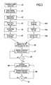
- An exemplifying sequence of steps that the control unit is configured or programmed to execute is shown in figure 3 : as a first step 40 the user is allowed to select the "treatment mode” and then he is allowed to select to enter in "dose control mode" at step 41. If the user selects to enter in "dose control mode", then the control unit may be configured to proceed according to different alternative solutions.
- control unit 10 can be configured to display on the user interface an indicium prompting (step 42) a user to select a dose option (e.g. effluent dose Q eff , convective dose Q rep +Q pbp +Q pfr , diffusive dose Q dial , urea dose, clearance dose) and an indicium prompting the user to enter initial set values of fluid flow rates, which depending upon the treatment mode may be one or more of the flow rates through lines 13, 15, 19, 21 and 25.
- a dose option e.g. effluent dose Q eff , convective dose Q rep +Q pbp +Q pfr , diffusive dose Q dial , urea dose, clearance dose
- the user may be requested to enter (step 43) the set flow rate values for 3 of: set flow rate through the dialysis fluid line, set flow rate through the infusion line, patient fluid removal rate, set flow rate through the effluent line; the fourth set flow rate value is normally calculated by the control unit as the algebraic sum of the rates just mentioned (step 45).
- the selected treatment is HD (pure hemodialysis) or HF (hemofiltration)
- the user will be requested to enter one set value less than in HDF.
- the user is also typically requested to enter the blood pump flow rate Q B .
- control unit is configured to receive said initial set values and to calculate the prescribed dose (step 44) based on said initial set values and on the selected dose option. Note the sequence of steps 44 and 45 is merely exemplificative and could be reversed.
- the control unit calculates the set average dose and the set value for the 4 th flow rate based on the 3 entered flow rate set values.
- the control unit can be configured to display on the user interface an indicium prompting a user to select the dose option (step 42) and an indicium prompting (step 43a) to enter: the prescribed dose for the selected dose option, the blood pump flow rate Q B and of the patient fluid removal rate Q pfr (step 44a).
- the control unit may be programmed to request the user to enter the prescribed dose D set eff , the value of the blood pump flow rate Q B and of the patient fluid removal rate Q pfr .
- the control unit can then be configured to calculate the set values of the other flow rates (Q dial , Q rep , Q eff ) at step 45a.
- control unit would calculate the set values for flow rates through the various lines (step 45a) as a function of the set dose, of the patient fluid removal rate and of a pre-determined algorithm.
- control unit can be configured perform steps 40, 41 and 42 and then to display on the user interface an indicium prompting a user to enter the prescribed dose value for the selected dose option as well as set values for the blood flow rate, the patient fluid removal rate and, depending on the selected treatment, for one or more of the infusion fluid flow rate (or rates) and the dialysis fluid flow rate.
- control unit 10 is configured to assign set initial values to one or more fluid flow rates (step 46 in figure 3 ) selected in the group including a fluid flow rate through the effluent line, a fluid flow rate through pre-dilution fluid line, a fluid flow rate through the post-dilution fluid line and a dialysis liquid fluid line.
- the control unit assigns initial set values for the dialysis fluid flow rate, the infusion fluid flow rate, and the patient fluid removal rate. These initial set flow rates are used by the control unit to control the means for regulating (e.g. pumps 17, 18, 21 referring to figure 1 ) during an initial period from treatment start (step 47).
- the control unit is also configured to periodically (e.g. at check intervals of 2 or 3 or 4 hours after start of the treatment, see step 48) execute a flow rate update procedure (step 49).
- the control unit can also be configured to run a first update procedure immediately before start of the treatment. Once the flow rate update procedure has been completed the various pumps are controlled with the new and updated flow rates (step 50) until a next time interval has passed. When a further time interval Ti has passed (step 51) a new flow rate update procedure (step 49) is run and new updated values for controlling the pumps calculated (step 50). The loop of steps 49, 50, 51 is then cyclically repeated.
- the update procedure (step 49) is designed in order to make sure that the prescribed dose for the selected dose option (e.g. the effluent dose D eff ) is actually achieved across a reference time interval, as it will explained herein below.
- the reference time interval may be set at 48 hours and a plurality of check points separated by check intervals are provided during the reference time; at each check point the control unit is configured to run the flow rate update procedure.
- control unit can be configured to regularly execute, e.g. periodically, at check points Ti during treatment, a flow rate update procedure (step 49) comprising the following steps:
- the above update procedure can be iteratively repeated at time intervals.
- the time interval of reference is basically 48 hours as mentioned above.
- the control unit can additionally be programmed to estimate an effective portion T eff of said next time period T prosp during which treatment will be actually delivered to the patient.
- the estimation of the effective portion T eff of the remaining treatment time allows the control unit to account for possible down times, or period of no treatment delivery (bag changes, disposable changes, alarms, etc. that may cause temporary stop of treatment delivery as either the blood flow of the flow in one or more fluid lines is interrupted) which may occur in the future and which may, however, be statistically forecasted with a certain degree of accuracy.
- the control unit can be configured to also consider and estimate the effective run time of pumps T eff to be expected over the coming time period T prosp . The determination of T eff is explained in a separate section here below.
- the change ⁇ Q eff can be balanced over Dialysate and Replacement flow rates only
- the change ⁇ Q eff can be balanced over all 3 flow rates: namely, PBP, Dialysate and Replacement flow rates.
- the change ⁇ Q eff can be balanced over one of PBP, Dialysate and Replacement flow rates.
- Estimating 'future' down times is the process needed to get T eff .
- the control unit is configured to execute such process.
- Several types of down-times can be estimated:
- CVVHDF treatment initially prescribed with:
- volume of dialysate and replacement solution containers e.g. solution bags
- the constant correction coefficient K is representative of the 2 nd item (alarms) of the list presented in the section "down times".
- Trun Tprosp-Tchange_set
- Tchange_bag 2 min
- Tdown bags Tdown bag_eff + Tdown bag_dal + Tdown bag_rep
- Tdown bags alpha 1 + alpha ⁇
- Trun - Tdown alarms alpha 1 + alpha ⁇ 1 - K alarms ⁇
- Trun with alpha Qeff Veff + Qdial Vdial + Qrep Vrep ⁇ T change_bag
- T eff Trun - Tdown alarms - Tdown bags
- the last equation (for Qeff1) includes the term T_eff, which is a function of effluent flow rate and other flows.
- T_eff is a function of effluent flow rate and other flows.
- the effective portion of the remaining treatment time can be calculated as a function of a number of K factors, which can at least in part be statistically determined, as explained in the section "down times".
- the control unit is configured to calculate, at a certain instant t during treatment, said updated flows based on: the dose need , which depends upon the delivered dose and the prescribed dose, the effective treatment time portion T eff .
- control unit will control the means for regulating the flow rate, e.g. pumps 21 and 18 in the example of figure 1 with the above new set values for the next time interval until the next check point (step 50).
- the control unit is also configured to automatically repeat the above described flow rate update procedure. For instance, the flow rate update procedure is periodically repeated after time periods of no less than two hours, preferably every 4 or 6 hours (see step 51).
- the control unit can also be configured to run a flow update procedure in case there is a change in the Dose prescription. In practice, the control unit detects the change in prescription and runs the flow update procedure thereafter.
- an update of flow parameters is performed immediately after a change of dose prescription.
- volume of dialysate and replacement solution containers e.g. solution bags
- Dose eff1 3500 ml/h.
- Dose gap has to be computed over each time period with constant dose.
- control unit is configured to give the operator several dose options, as already mentioned, namely:
- the flow rates update procedure takes into account for the dose option and for the selected treatment.
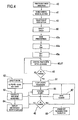
- FIG 4 schematically shows further aspects of the invention and relates to an alternative sequence of steps the control unit 1 may be configured to execute. Steps common to those described in connection with figure 3 are referenced with same numerals and are not described again.
- the control unit may be programmed to check (step 60 in figure 4 ) whether the selected treatment mode and the dose control mode are conflicting modes and prevent from entering in dose control mode in case of conflict between the selected treatment mode and the dose control mode. For instance, in case a treatment mode is selected where use is made of said pre-blood pump infusion line for regional anticoagulation using e.g. citrate then entering in dose control mode is prevented.
- control unit is configured to receive a set prescription for the hourly dose of e.g. the effluent fluid (step 43a) and set values for the blood flow Q B and patient fluid removal rate Q PFR rate (step 44a) and to receive or calculate initial set values for the dialysis and replacement fluid flow rates (45a).
- the above rates are set as initial values and implemented by the control unit controlling the respective pumps.
- a flow rate update procedure step 61
- flow rate update procedure e.g. comprising steps as described in above section "flow rate update procedure" is executed.
- control unit will run a safety check to make sure that the new flow rates are compatible with certain safety criteria (step 62): for instance each set flow rate cannot pass a respective maximum threshold value; moreover, the variation between the values of each updated flow rate and the respective previous flow rate (which can be one of the initial flow rates or a previously updated flow rate value) should preferably not be excessive and is also controlled to be below a respective threshold.
- control unit 10 can be configured to also calculate a maximum achievable dose (step 63) within said safety criteria, and to assess whether said prescribed dose can be reached.
- control unit can be configured to control the means for regulating the flow rates such as to achieve the prescribed dose within the prescribed time interval.
- control unit could be configured to control the means for regulating the flow rates to achieve the maximum dose possible within said prescribed time interval in a manner compatible with the safety criteria.
- control unit is programmed to calculate a remaining dose as a difference between the prescribed dose and the maximum dose actually achievable within the prescribed time interval.
- the control unit is designed to control the apparatus in term of flow rates, thus after a number of check points it may be possible to recover the any remaining dose accumulated in previous time intervals (step 66).
- control unit may be programmed to display on the user interface 12 the calculated updated set of values for said flow rates, and to prompt user to confirm the updated set of values (step 64) for said flow rates before using the updated values for controlling the means for regulating (step 65). If the user approves the updated set of values, then the control unit 10 is programmed to use the updated flow rate values as new set values for controlling the means for regulating the fluid flow through the fluid flow lines.
- step 64 the step of displaying the updated values and asking for user's approval (step 64) is optional.
- the step of calculating updated values of the flow rates is affected by the selected dose option and by the type of apparatus and treatment mode selected. For instance if the effluent dose is the dose option and if the treatment mode is a pure HF (i.e. there is no dialysis liquid container), then the flow rate update procedure will not generate an updated dialysis fluid flow rate.
- the step of calculating the updated set of values comprises calculating an updated infusion pump flow rate and an updated dialysis pump flow rate, as above described with reference to figure 1 .
- the updated infusion pump flow rate and the updated dialysis fluid flow rate differ from their respective initial values by a same percentage.
- the step of calculating the updated set of values may comprise calculating an updated infusion pump flow rate without changing the dialysis pump flow rate: in other words if the effluent volume dose is the dose to be achieved the control unit may be configured to achieve said dose without varying the dialysis fluid flow rate and only acting on the effluent pump and on the infusion pump.
- the control unit may be programmed to only update the dialysis fluid flow rate and not the infusion fluid flow rate: this is typically the case when the infusion line is a pre-dilution line, i.e. an infusion line connected upstream the filtration unit in a so called "pre dilution" configuration.
- control unit can be configured for calculating an updated infusion pump flow rate by calculating an updated pre-dilution pump flow rate and an updated post-dilution pump flow rate: the updated pre-dilution pump flow rate and the updated post-dilution pump fluid flow rate may differ from their respective initial values by a same percentage.
- control unit is configured during the flow update procedure to leave the set blood pump flow rate unchanged to its initial set value.
- control unit 10 is programmed to allow a user to vary the initial value for the dose of the substance.
- control unit is programmed to receive the new dose value (step 67) and to calculate corresponding updated values for the flow rates through the fluid flow lines in order to arrive as close as possible and possibly match said new dose value.
- a first value for the prescribed dose (D 0 ) can be entered before treatment start (T 0 ); then after a while (instant T t ) from treatment start, a second different value of the prescribed dose (D 1 ) to be reached can be entered.
- the control unit after receipt of said second value, is configured to calculate the updated set of values based upon:
- control unit can also be programmed to account for the fraction of dose D t already delivered at time T t and for the effective remaining treatment time K*(T-T t ).
- the apparatus 1 also comprises a first scale 32 operative for providing weight information relative to the amount of the fluid collected in the effluent fluid container 14; a second scale 33 operative for providing weight information relative to the amount of the fluid supplied from the infusion fluid container 16; a third scale 34 operative for providing weight information relative to the amount of the fluid supplied from dialysis fluid container 20.
- a respective fourth and fifth scale 36 and 37 could be present to provide weight information relative to the amount of fluid supplied from infusion container 23 and from infusion container 26.
- the scales are all connected to the control unit and provide said weight information for the control unit to determine the actual quantity of fluid in each container as well as the actual flow rate of fluid supplied by or received in each container.
- the control unit 10 may then be configured to receive treatment selection information and check if the user entered into dose control mode.
- the control unit can also be configured to receive weight information from the first scale and, depending upon the selected treatment, from the scales associated to the container supplying the lines involved in the delivery of the selected treatment) and to control, at least at the beginning of the treatment, the flow rate of at least one of the effluent fluid, the infusion fluid, the dialysis fluid by controlling said means for regulating based on said weight information, and said initial set values.
- control unit is configured to execute the flow update procedure as above described calculating said updated set of values, and subsequent to each said calculation, controlling the flow rate of at least one of the effluent fluid, the infusion fluid, the dialysis fluid by controlling said means for regulating based on said weight information, and said updated set of values.
- one or more, optionally all containers 14, 16, 20, 23 may be disposable plastic containers, preferably bags which are hang on a support carried by the respective scale. All lines and the filtration unit may also be plastic disposable components which can be mounted at the beginning of the treatment session and then disposed of at the end of the treatment session.
- the means for regulating typically may comprise pumps, although other regulating means as valves or combinations of valves and pumps could be used.
- the scales may comprise piezoelectric sensors, or strain gauges, or spring sensors, or any other type of transducer able to sense forces applied thereon.
Priority Applications (6)
| Application Number | Priority Date | Filing Date | Title |
|---|---|---|---|
| ES10010805.9T ES2498744T3 (es) | 2010-09-27 | 2010-09-27 | Aparato para el tratamiento extracorpóreo de sangre |
| PL10010805T PL2433662T3 (pl) | 2010-09-27 | 2010-09-27 | Urządzenie do pozaustrojowego oczyszczania krwi |
| EP10010805.9A EP2433662B1 (fr) | 2010-09-27 | 2010-09-27 | Appareil pour le traitement extracorporel du sang |
| US13/876,357 US10737011B2 (en) | 2010-09-27 | 2011-09-08 | Apparatus for extracorporeal treatment of blood |
| PCT/IB2011/002098 WO2012042323A2 (fr) | 2010-09-27 | 2011-09-08 | Appareil de traitement extracorporel du sang |
| US16/936,659 US20200345922A1 (en) | 2010-09-27 | 2020-07-23 | Apparatus for extracorporeal treatment of blood |
Applications Claiming Priority (1)
| Application Number | Priority Date | Filing Date | Title |
|---|---|---|---|
| EP10010805.9A EP2433662B1 (fr) | 2010-09-27 | 2010-09-27 | Appareil pour le traitement extracorporel du sang |
Publications (2)
| Publication Number | Publication Date |
|---|---|
| EP2433662A1 true EP2433662A1 (fr) | 2012-03-28 |
| EP2433662B1 EP2433662B1 (fr) | 2014-06-04 |
Family
ID=43587114
Family Applications (1)
| Application Number | Title | Priority Date | Filing Date |
|---|---|---|---|
| EP10010805.9A Active EP2433662B1 (fr) | 2010-09-27 | 2010-09-27 | Appareil pour le traitement extracorporel du sang |
Country Status (5)
| Country | Link |
|---|---|
| US (2) | US10737011B2 (fr) |
| EP (1) | EP2433662B1 (fr) |
| ES (1) | ES2498744T3 (fr) |
| PL (1) | PL2433662T3 (fr) |
| WO (1) | WO2012042323A2 (fr) |
Cited By (3)
| Publication number | Priority date | Publication date | Assignee | Title |
|---|---|---|---|---|
| WO2016042078A1 (fr) * | 2014-09-18 | 2016-03-24 | Fresenius Medical Care Deutschland Gmbh | Procédé et dispositif de commande d'un dispositif de traitement du sang en tenant compte des réactions du patient pendant le traitement du sang, ainsi que dispositif de traitement du sang |
| US10052423B2 (en) | 2011-08-30 | 2018-08-21 | Gambro Lundia Ab | Apparatus for extracorporeal treatment of blood and process of calculating set flow rates in a medical apparatus for delivery or collection of fluids |
| US10737011B2 (en) | 2010-09-27 | 2020-08-11 | Gambro Lundia Ab | Apparatus for extracorporeal treatment of blood |
Families Citing this family (33)
| Publication number | Priority date | Publication date | Assignee | Title |
|---|---|---|---|---|
| US9399091B2 (en) | 2009-09-30 | 2016-07-26 | Medtronic, Inc. | System and method to regulate ultrafiltration |
| US9700661B2 (en) | 2011-04-29 | 2017-07-11 | Medtronic, Inc. | Chronic pH or electrolyte monitoring |
| EP3165245B1 (fr) | 2011-08-02 | 2019-02-20 | Medtronic, Inc. | Système d'hémodialyse possédant un circuit de flux avec un volume à conformité régulée |
| WO2013025844A2 (fr) | 2011-08-16 | 2013-02-21 | Medtronic, Inc. | Système d'hémodialyse modulaire |
| US10905816B2 (en) | 2012-12-10 | 2021-02-02 | Medtronic, Inc. | Sodium management system for hemodialysis |
| US10543052B2 (en) | 2013-02-01 | 2020-01-28 | Medtronic, Inc. | Portable dialysis cabinet |
| US10010663B2 (en) | 2013-02-01 | 2018-07-03 | Medtronic, Inc. | Fluid circuit for delivery of renal replacement therapies |
| US10850016B2 (en) | 2013-02-01 | 2020-12-01 | Medtronic, Inc. | Modular fluid therapy system having jumpered flow paths and systems and methods for cleaning and disinfection |
| US9623164B2 (en) | 2013-02-01 | 2017-04-18 | Medtronic, Inc. | Systems and methods for multifunctional volumetric fluid control |
| US9827361B2 (en) | 2013-02-02 | 2017-11-28 | Medtronic, Inc. | pH buffer measurement system for hemodialysis systems |
| EP3102107A4 (fr) | 2013-11-04 | 2018-02-07 | Medtronic, Inc. | Procédé et dispositif pour gérer des volumes de fluides dans le corps |
| US9713665B2 (en) | 2014-12-10 | 2017-07-25 | Medtronic, Inc. | Degassing system for dialysis |
| US10874787B2 (en) | 2014-12-10 | 2020-12-29 | Medtronic, Inc. | Degassing system for dialysis |
| US10098993B2 (en) | 2014-12-10 | 2018-10-16 | Medtronic, Inc. | Sensing and storage system for fluid balance |
| US9895479B2 (en) | 2014-12-10 | 2018-02-20 | Medtronic, Inc. | Water management system for use in dialysis |
| JP6547592B2 (ja) * | 2015-11-04 | 2019-07-24 | ニプロ株式会社 | 血液浄化装置 |
| US10874790B2 (en) | 2016-08-10 | 2020-12-29 | Medtronic, Inc. | Peritoneal dialysis intracycle osmotic agent adjustment |
| US10994064B2 (en) | 2016-08-10 | 2021-05-04 | Medtronic, Inc. | Peritoneal dialysate flow path sensing |
| US11013843B2 (en) | 2016-09-09 | 2021-05-25 | Medtronic, Inc. | Peritoneal dialysis fluid testing system |
| US11278654B2 (en) | 2017-12-07 | 2022-03-22 | Medtronic, Inc. | Pneumatic manifold for a dialysis system |
| US11033667B2 (en) | 2018-02-02 | 2021-06-15 | Medtronic, Inc. | Sorbent manifold for a dialysis system |
| US11110215B2 (en) | 2018-02-23 | 2021-09-07 | Medtronic, Inc. | Degasser and vent manifolds for dialysis |
| JP7098433B2 (ja) * | 2018-06-20 | 2022-07-11 | 日機装株式会社 | 血液浄化装置及び血液浄化装置による血漿流量取得方法 |
| US11806457B2 (en) | 2018-11-16 | 2023-11-07 | Mozarc Medical Us Llc | Peritoneal dialysis adequacy meaurements |
| US11806456B2 (en) | 2018-12-10 | 2023-11-07 | Mozarc Medical Us Llc | Precision peritoneal dialysis therapy based on dialysis adequacy measurements |
| AU2020401135A1 (en) * | 2019-12-10 | 2022-06-23 | Baxter Healthcare Sa | Combined extracorporeal and drug delivery system and method |
| IT202000026212A1 (it) * | 2020-11-03 | 2022-05-03 | Gambro Lundia Ab | Apparecchio per il trattamento extracorporeo del sangue e processo di calcolo delle portate impostate in un apparecchio medico per il trattamento extracorporeo del sangue |
| IT202000026209A1 (it) * | 2020-11-03 | 2022-05-03 | Gambro Lundia Ab | Apparatus for extracorporeal treatment of blood and process of calculating set flow rates in a medical apparatus for extracorporeal treatment of blood |
| IT202000026206A1 (it) * | 2020-11-03 | 2022-05-03 | Gambro Lundia Ab | Apparecchio per il trattamento extracorporeo del sangue e processo di calcolo delle portate impostate in un apparecchio medico per il trattamento extracorporeo del sangue. |
| US11850344B2 (en) | 2021-08-11 | 2023-12-26 | Mozarc Medical Us Llc | Gas bubble sensor |
| US11965763B2 (en) | 2021-11-12 | 2024-04-23 | Mozarc Medical Us Llc | Determining fluid flow across rotary pump |
| US11944733B2 (en) | 2021-11-18 | 2024-04-02 | Mozarc Medical Us Llc | Sodium and bicarbonate control |
| WO2023212347A1 (fr) * | 2022-04-28 | 2023-11-02 | Regents Of The University Of Michigan | Architecture en boucle fermée pour distribuer et administrer des médicaments à des patients |
Citations (6)
| Publication number | Priority date | Publication date | Assignee | Title |
|---|---|---|---|---|
| EP0547025A1 (fr) | 1988-03-03 | 1993-06-16 | Gambro Ab | Méthode pour déterminer la concentration d'une substance dans le sang ou la dialysance d'un dialyseur. |
| EP0658352A1 (fr) | 1993-12-17 | 1995-06-21 | Hospal Ag | Procédé de détermination d'un paramètre significatif du progrès d'un traitement extracorporel de sang |
| WO1998023311A1 (fr) * | 1996-11-28 | 1998-06-04 | Gambro Ab | Methode et systeme de prevention de symptomatologie intradialytique |
| EP0920887A1 (fr) | 1997-11-04 | 1999-06-09 | Georg Ahlbäumer | Jambière avec stabilisation de la cheville |
| US20060054215A1 (en) * | 2003-01-24 | 2006-03-16 | Gerard Remkes | Method and device for supply of a dialysis unit with dialysis fluid |
| US20100168925A1 (en) * | 2006-06-08 | 2010-07-01 | Peter Hilgers | Device and method for controlling an extracorporeal blood- treating apparatus |
Family Cites Families (40)
| Publication number | Priority date | Publication date | Assignee | Title |
|---|---|---|---|---|
| DE3442744A1 (de) | 1984-11-23 | 1986-06-05 | Fresenius AG, 6380 Bad Homburg | Dialysegeraet mit einer einrichtung zur wiederverwendung von haemodialysatoren |
| US4731731A (en) * | 1985-02-21 | 1988-03-15 | Cochran Michael J | Dialysis machine having enhanced D/A resolution |
| FR2680318B1 (fr) | 1991-08-14 | 1994-01-21 | Hospal Industrie | Rein artificiel et procede de commande. |
| US5378227A (en) * | 1992-08-11 | 1995-01-03 | Cobe Laboratories, Inc. | Biological/pharmaceutical method and apparatus for collecting and mixing fluids |
| US5389078A (en) * | 1993-10-06 | 1995-02-14 | Sims Deltec, Inc. | Programmable infusion pump for administering medication to patients |
| JPH07328110A (ja) * | 1994-06-10 | 1995-12-19 | Nissho Corp | 透析装置の除水制御機構 |
| EP0980275A1 (fr) * | 1997-05-07 | 2000-02-23 | Infomed S.A. | Procede de controle de dispositif d'epuration de sang |
| US8105258B2 (en) * | 1999-04-26 | 2012-01-31 | Baxter International Inc. | Citrate anticoagulation system for extracorporeal blood treatments |
| DE19928407C1 (de) | 1999-06-22 | 2000-10-26 | Fresenius Medical Care De Gmbh | Verfahren zur Bestimmung der Leistungsfähigkeit eines Dialysators einer Dialysevorrichtung und Dialysevorrichtung zur Durchführung des Verfahrens |
| IT1320024B1 (it) | 2000-04-07 | 2003-11-12 | Gambro Dasco Spa | Metodo per la regolazione della infusione in una macchina di dialisi e macchina di dialisi per l'applicazione del citato metodo. |
| JP2004503301A (ja) | 2000-06-15 | 2004-02-05 | ガンブロ ルンデイア アクチーボラグ | 透析においてカルシウムのプロファイルを作る方法および装置 |
| JP4267917B2 (ja) | 2001-02-07 | 2009-05-27 | ネフロス・インコーポレーテッド | ダイアフィルトレーションモジュール |
| SE523610C2 (sv) | 2001-10-02 | 2004-05-04 | Gambro Lundia Ab | Metod vid styrning av dialysanordning |
| DE10212247C1 (de) | 2002-03-19 | 2003-12-18 | Fresenius Medical Care De Gmbh | Verfahren zur Bestimmung eines Behandlungsparameters an einer Hämofiltrationsvorrichtung und Hämofiltrationsvorrichtung zur Anwendung des Verfahrens |
| DE10213179C1 (de) | 2002-03-25 | 2003-08-07 | Fresenius Medical Care De Gmbh | Verfahren und Vorrichtung zur Überwachung der Zufuhr von Substitutionsflüssigkeit während einer extrakorporalen Blutbehandlung |
| US20050008576A1 (en) * | 2002-04-01 | 2005-01-13 | Munzer Makansi | Carrier foam to enhance liquid functional performance |
| DE10218846C1 (de) | 2002-04-27 | 2003-09-18 | Fresenius Medical Care De Gmbh | Verfahren zur Unterbrechung oder Fortführung einer extrakorporalen Blutbehandlung mit veränderten Flussraten und Vorrichtung zur extrakorporalen Blutbehandlung |
| DE60204883T3 (de) * | 2002-09-05 | 2013-10-24 | Gambro Lundia Ab | Steuerung für eine Blutbehandlungsvorrichtung |
| FR2848857B1 (fr) | 2002-12-20 | 2005-09-16 | Gambro Lundia Ab | Dispositif et ligne a usage unique pour le traitement extracorporel du sang par anticoagulation au citrate |
| US7291269B2 (en) | 2003-03-17 | 2007-11-06 | Gambro Lundia Ab | Apparatus and process for extracorporeal treatment of blood with selective extraction of solutes |
| DE10317024A1 (de) | 2003-04-11 | 2004-11-11 | Fresenius Medical Care Deutschland Gmbh | Blutbehandlungsvorrichtung |
| ITMO20030259A1 (it) * | 2003-09-25 | 2005-03-26 | Gambro Lundia Ab | User interface per una macchina per il trattamento |
| US7029456B2 (en) * | 2003-10-15 | 2006-04-18 | Baxter International Inc. | Medical fluid therapy flow balancing and synchronization system |
| CN1946441B (zh) | 2004-05-07 | 2011-04-13 | 甘布罗伦迪亚股份公司 | 血液处理设备和用来控制注入的方法 |
| US7408178B2 (en) * | 2004-07-01 | 2008-08-05 | Fei Company | Method for the removal of a microscopic sample from a substrate |
| US20060009734A1 (en) * | 2004-07-07 | 2006-01-12 | Martin James F | Dosage control for drug delivery system |
| ITMO20040191A1 (it) | 2004-07-23 | 2004-10-23 | Gambro Lundia Ab | Macchina e metodo per il trattamento extracorporeo di sangue. |
| EP1998826B1 (fr) * | 2006-02-22 | 2016-02-17 | Henry Ford Health System | Système et procédé pour l'administration d'anticoagulation régionale au citrate à des circuits sanguins extracorporels |
| DE102006032926A1 (de) | 2006-07-15 | 2008-01-17 | Fresenius Medical Care Deutschland Gmbh | Verfahren und Vorrichtung zur Vorgabe von Behandlungsparametern für extrakorporale Dialysebehandlungen |
| DE102006045437A1 (de) | 2006-09-26 | 2008-04-03 | Fresenius Medical Care Deutschland Gmbh | Vorrichtung und Verfahren zur Vorgabe einer Dialysierflüssigkeitsrate oder Blutflussrate für eine extrakorporale Blutbehandlung |
| US8246566B2 (en) | 2006-12-22 | 2012-08-21 | Baxter International Inc. | Total fluid loss control system |
| EP2150292B1 (fr) | 2007-05-04 | 2018-10-10 | Fresenius Medical Care Deutschland GmbH | Dispositif de contrôle d'une unité de traitement du sang d'un dispositif de traitement du sang extracorporel |
| DE102007052571A1 (de) | 2007-11-03 | 2009-05-07 | Fresenius Medical Care Deutschland Gmbh | Verfahren und Vorrichtung zur Überwachung der Zufuhr von Substitutionsflüssigkeit während einer extrakorporalen Blutbehandlung |
| CA2724060C (fr) | 2008-05-26 | 2014-04-08 | Gambro Lundia Ab | Appareil d'hemodialyse ou d'hemo(dia)filtration et procede de controle d'un appareil d'hemodialyse ou d'hemo(dia)filtration |
| ITMO20080159A1 (it) | 2008-05-27 | 2009-11-28 | Gambro Lundia Ab | Circuito fluido medicale. |
| WO2010029401A2 (fr) | 2008-09-09 | 2010-03-18 | Gambro Lundia Ab | Procédure et dispositif de traitement sanguin extracorporel utilisant une anti-coagulation au citrate |
| ATE552868T1 (de) | 2008-09-15 | 2012-04-15 | Braun B Avitum Ag | Verfahren zur bestimmung des kt/v-parameters bei nierenersatzbehandlungen basierend auf einem nicht-linearen passungsverfahren |
| EP2163272B1 (fr) | 2008-09-15 | 2014-06-25 | B. Braun Avitum AG | Dispositif pour prédire rapidement le paramètre Kt/V dans les traitements de substitution des reins |
| EP2349379B1 (fr) | 2008-10-14 | 2014-01-22 | Gambro Lundia AB | Appareil et méthode destinés au traitement du sang |
| EP2433662B1 (fr) | 2010-09-27 | 2014-06-04 | Gambro Lundia AB | Appareil pour le traitement extracorporel du sang |
-
2010
- 2010-09-27 EP EP10010805.9A patent/EP2433662B1/fr active Active
- 2010-09-27 PL PL10010805T patent/PL2433662T3/pl unknown
- 2010-09-27 ES ES10010805.9T patent/ES2498744T3/es active Active
-
2011
- 2011-09-08 US US13/876,357 patent/US10737011B2/en active Active
- 2011-09-08 WO PCT/IB2011/002098 patent/WO2012042323A2/fr active Application Filing
-
2020
- 2020-07-23 US US16/936,659 patent/US20200345922A1/en active Pending
Patent Citations (6)
| Publication number | Priority date | Publication date | Assignee | Title |
|---|---|---|---|---|
| EP0547025A1 (fr) | 1988-03-03 | 1993-06-16 | Gambro Ab | Méthode pour déterminer la concentration d'une substance dans le sang ou la dialysance d'un dialyseur. |
| EP0658352A1 (fr) | 1993-12-17 | 1995-06-21 | Hospal Ag | Procédé de détermination d'un paramètre significatif du progrès d'un traitement extracorporel de sang |
| WO1998023311A1 (fr) * | 1996-11-28 | 1998-06-04 | Gambro Ab | Methode et systeme de prevention de symptomatologie intradialytique |
| EP0920887A1 (fr) | 1997-11-04 | 1999-06-09 | Georg Ahlbäumer | Jambière avec stabilisation de la cheville |
| US20060054215A1 (en) * | 2003-01-24 | 2006-03-16 | Gerard Remkes | Method and device for supply of a dialysis unit with dialysis fluid |
| US20100168925A1 (en) * | 2006-06-08 | 2010-07-01 | Peter Hilgers | Device and method for controlling an extracorporeal blood- treating apparatus |
Cited By (4)
| Publication number | Priority date | Publication date | Assignee | Title |
|---|---|---|---|---|
| US10737011B2 (en) | 2010-09-27 | 2020-08-11 | Gambro Lundia Ab | Apparatus for extracorporeal treatment of blood |
| US10052423B2 (en) | 2011-08-30 | 2018-08-21 | Gambro Lundia Ab | Apparatus for extracorporeal treatment of blood and process of calculating set flow rates in a medical apparatus for delivery or collection of fluids |
| US10918776B2 (en) | 2011-08-30 | 2021-02-16 | Gambro Lundia Ab | Apparatus for extracorporeal treatment of blood including calculation of flow rates therefore |
| WO2016042078A1 (fr) * | 2014-09-18 | 2016-03-24 | Fresenius Medical Care Deutschland Gmbh | Procédé et dispositif de commande d'un dispositif de traitement du sang en tenant compte des réactions du patient pendant le traitement du sang, ainsi que dispositif de traitement du sang |
Also Published As
| Publication number | Publication date |
|---|---|
| EP2433662B1 (fr) | 2014-06-04 |
| US20130248426A1 (en) | 2013-09-26 |
| WO2012042323A3 (fr) | 2014-09-12 |
| WO2012042323A2 (fr) | 2012-04-05 |
| PL2433662T3 (pl) | 2014-10-31 |
| US20200345922A1 (en) | 2020-11-05 |
| US10737011B2 (en) | 2020-08-11 |
| ES2498744T3 (es) | 2014-09-25 |
Similar Documents
| Publication | Publication Date | Title |
|---|---|---|
| US20200345922A1 (en) | Apparatus for extracorporeal treatment of blood | |
| US11207451B2 (en) | Medical apparatus for extracorporeal treatment of fluid and a process of calculating set flow rates in a medical apparatus for delivery or collection of fluids | |
| US10258726B2 (en) | Process of controlling an apparatus for extracorporeal treatment of blood | |
| EP2564885B1 (fr) | Appareil pour traitement extra-corporel de sang et procédé de calcul de l'écoulement dans un appareil médical pour la fourniture ou la collecte de fluides | |
| EP2688601B1 (fr) | Appareil pour traitement sanguin extracorporel | |
| JP5221613B2 (ja) | 血液処理設備のための制御装置および制御方法 | |
| EP2687248B1 (fr) | Appareil et procédé permettant de déterminer un paramètre indicatif de la progression d'un traitement sanguin extracorporel | |
| US11311655B2 (en) | Apparatus and method for determining a parameter indicative of the progress of an extracorporeal blood treatment |
Legal Events
| Date | Code | Title | Description |
|---|---|---|---|
| PUAI | Public reference made under article 153(3) epc to a published international application that has entered the european phase |
Free format text: ORIGINAL CODE: 0009012 |
|
| AK | Designated contracting states |
Kind code of ref document: A1 Designated state(s): AL AT BE BG CH CY CZ DE DK EE ES FI FR GB GR HR HU IE IS IT LI LT LU LV MC MK MT NL NO PL PT RO SE SI SK SM TR |
|
| AX | Request for extension of the european patent |
Extension state: BA ME RS |
|
| 17P | Request for examination filed |
Effective date: 20120416 |
|
| 17Q | First examination report despatched |
Effective date: 20130304 |
|
| GRAP | Despatch of communication of intention to grant a patent |
Free format text: ORIGINAL CODE: EPIDOSNIGR1 |
|
| INTG | Intention to grant announced |
Effective date: 20140130 |
|
| GRAS | Grant fee paid |
Free format text: ORIGINAL CODE: EPIDOSNIGR3 |
|
| GRAA | (expected) grant |
Free format text: ORIGINAL CODE: 0009210 |
|
| AK | Designated contracting states |
Kind code of ref document: B1 Designated state(s): AL AT BE BG CH CY CZ DE DK EE ES FI FR GB GR HR HU IE IS IT LI LT LU LV MC MK MT NL NO PL PT RO SE SI SK SM TR |
|
| REG | Reference to a national code |
Ref country code: GB Ref legal event code: FG4D |
|
| REG | Reference to a national code |
Ref country code: CH Ref legal event code: EP |
|
| REG | Reference to a national code |
Ref country code: AT Ref legal event code: REF Ref document number: 670673 Country of ref document: AT Kind code of ref document: T Effective date: 20140615 |
|
| REG | Reference to a national code |
Ref country code: IE Ref legal event code: FG4D |
|
| REG | Reference to a national code |
Ref country code: DE Ref legal event code: R096 Ref document number: 602010016387 Country of ref document: DE Effective date: 20140717 |
|
| REG | Reference to a national code |
Ref country code: ES Ref legal event code: FG2A Ref document number: 2498744 Country of ref document: ES Kind code of ref document: T3 Effective date: 20140925 |
|
| REG | Reference to a national code |
Ref country code: AT Ref legal event code: MK05 Ref document number: 670673 Country of ref document: AT Kind code of ref document: T Effective date: 20140604 |
|
| REG | Reference to a national code |
Ref country code: NL Ref legal event code: VDEP Effective date: 20140604 |
|
| PG25 | Lapsed in a contracting state [announced via postgrant information from national office to epo] |
Ref country code: FI Free format text: LAPSE BECAUSE OF FAILURE TO SUBMIT A TRANSLATION OF THE DESCRIPTION OR TO PAY THE FEE WITHIN THE PRESCRIBED TIME-LIMIT Effective date: 20140604 Ref country code: NO Free format text: LAPSE BECAUSE OF FAILURE TO SUBMIT A TRANSLATION OF THE DESCRIPTION OR TO PAY THE FEE WITHIN THE PRESCRIBED TIME-LIMIT Effective date: 20140904 Ref country code: GR Free format text: LAPSE BECAUSE OF FAILURE TO SUBMIT A TRANSLATION OF THE DESCRIPTION OR TO PAY THE FEE WITHIN THE PRESCRIBED TIME-LIMIT Effective date: 20140905 Ref country code: LT Free format text: LAPSE BECAUSE OF FAILURE TO SUBMIT A TRANSLATION OF THE DESCRIPTION OR TO PAY THE FEE WITHIN THE PRESCRIBED TIME-LIMIT Effective date: 20140604 Ref country code: CY Free format text: LAPSE BECAUSE OF FAILURE TO SUBMIT A TRANSLATION OF THE DESCRIPTION OR TO PAY THE FEE WITHIN THE PRESCRIBED TIME-LIMIT Effective date: 20140604 |
|
| REG | Reference to a national code |
Ref country code: PL Ref legal event code: T3 |
|
| REG | Reference to a national code |
Ref country code: LT Ref legal event code: MG4D |
|
| PG25 | Lapsed in a contracting state [announced via postgrant information from national office to epo] |
Ref country code: LV Free format text: LAPSE BECAUSE OF FAILURE TO SUBMIT A TRANSLATION OF THE DESCRIPTION OR TO PAY THE FEE WITHIN THE PRESCRIBED TIME-LIMIT Effective date: 20140604 Ref country code: HR Free format text: LAPSE BECAUSE OF FAILURE TO SUBMIT A TRANSLATION OF THE DESCRIPTION OR TO PAY THE FEE WITHIN THE PRESCRIBED TIME-LIMIT Effective date: 20140604 Ref country code: AT Free format text: LAPSE BECAUSE OF FAILURE TO SUBMIT A TRANSLATION OF THE DESCRIPTION OR TO PAY THE FEE WITHIN THE PRESCRIBED TIME-LIMIT Effective date: 20140604 Ref country code: SE Free format text: LAPSE BECAUSE OF FAILURE TO SUBMIT A TRANSLATION OF THE DESCRIPTION OR TO PAY THE FEE WITHIN THE PRESCRIBED TIME-LIMIT Effective date: 20140604 |
|
| PG25 | Lapsed in a contracting state [announced via postgrant information from national office to epo] |
Ref country code: PT Free format text: LAPSE BECAUSE OF FAILURE TO SUBMIT A TRANSLATION OF THE DESCRIPTION OR TO PAY THE FEE WITHIN THE PRESCRIBED TIME-LIMIT Effective date: 20141006 Ref country code: EE Free format text: LAPSE BECAUSE OF FAILURE TO SUBMIT A TRANSLATION OF THE DESCRIPTION OR TO PAY THE FEE WITHIN THE PRESCRIBED TIME-LIMIT Effective date: 20140604 Ref country code: CZ Free format text: LAPSE BECAUSE OF FAILURE TO SUBMIT A TRANSLATION OF THE DESCRIPTION OR TO PAY THE FEE WITHIN THE PRESCRIBED TIME-LIMIT Effective date: 20140604 Ref country code: RO Free format text: LAPSE BECAUSE OF FAILURE TO SUBMIT A TRANSLATION OF THE DESCRIPTION OR TO PAY THE FEE WITHIN THE PRESCRIBED TIME-LIMIT Effective date: 20140604 Ref country code: SK Free format text: LAPSE BECAUSE OF FAILURE TO SUBMIT A TRANSLATION OF THE DESCRIPTION OR TO PAY THE FEE WITHIN THE PRESCRIBED TIME-LIMIT Effective date: 20140604 |
|
| PG25 | Lapsed in a contracting state [announced via postgrant information from national office to epo] |
Ref country code: NL Free format text: LAPSE BECAUSE OF FAILURE TO SUBMIT A TRANSLATION OF THE DESCRIPTION OR TO PAY THE FEE WITHIN THE PRESCRIBED TIME-LIMIT Effective date: 20140604 Ref country code: IS Free format text: LAPSE BECAUSE OF FAILURE TO SUBMIT A TRANSLATION OF THE DESCRIPTION OR TO PAY THE FEE WITHIN THE PRESCRIBED TIME-LIMIT Effective date: 20141004 |
|
| REG | Reference to a national code |
Ref country code: DE Ref legal event code: R026 Ref document number: 602010016387 Country of ref document: DE |
|
| PLBI | Opposition filed |
Free format text: ORIGINAL CODE: 0009260 |
|
| 26 | Opposition filed |
Opponent name: B. BRAUN AVITUM AG Effective date: 20150304 |
|
| PLAX | Notice of opposition and request to file observation + time limit sent |
Free format text: ORIGINAL CODE: EPIDOSNOBS2 |
|
| PG25 | Lapsed in a contracting state [announced via postgrant information from national office to epo] |
Ref country code: DK Free format text: LAPSE BECAUSE OF FAILURE TO SUBMIT A TRANSLATION OF THE DESCRIPTION OR TO PAY THE FEE WITHIN THE PRESCRIBED TIME-LIMIT Effective date: 20140604 Ref country code: LU Free format text: LAPSE BECAUSE OF FAILURE TO SUBMIT A TRANSLATION OF THE DESCRIPTION OR TO PAY THE FEE WITHIN THE PRESCRIBED TIME-LIMIT Effective date: 20140927 Ref country code: MC Free format text: LAPSE BECAUSE OF FAILURE TO SUBMIT A TRANSLATION OF THE DESCRIPTION OR TO PAY THE FEE WITHIN THE PRESCRIBED TIME-LIMIT Effective date: 20140604 |
|
| REG | Reference to a national code |
Ref country code: CH Ref legal event code: PL |
|
| REG | Reference to a national code |
Ref country code: DE Ref legal event code: R026 Ref document number: 602010016387 Country of ref document: DE Effective date: 20150304 |
|
| REG | Reference to a national code |
Ref country code: IE Ref legal event code: MM4A |
|
| REG | Reference to a national code |
Ref country code: FR Ref legal event code: PLFP Year of fee payment: 6 |
|
| PG25 | Lapsed in a contracting state [announced via postgrant information from national office to epo] |
Ref country code: SI Free format text: LAPSE BECAUSE OF FAILURE TO SUBMIT A TRANSLATION OF THE DESCRIPTION OR TO PAY THE FEE WITHIN THE PRESCRIBED TIME-LIMIT Effective date: 20140604 Ref country code: LI Free format text: LAPSE BECAUSE OF NON-PAYMENT OF DUE FEES Effective date: 20140930 Ref country code: CH Free format text: LAPSE BECAUSE OF NON-PAYMENT OF DUE FEES Effective date: 20140930 |
|
| PLAF | Information modified related to communication of a notice of opposition and request to file observations + time limit |
Free format text: ORIGINAL CODE: EPIDOSCOBS2 |
|
| PG25 | Lapsed in a contracting state [announced via postgrant information from national office to epo] |
Ref country code: IE Free format text: LAPSE BECAUSE OF NON-PAYMENT OF DUE FEES Effective date: 20140927 |
|
| PLBB | Reply of patent proprietor to notice(s) of opposition received |
Free format text: ORIGINAL CODE: EPIDOSNOBS3 |
|
| PG25 | Lapsed in a contracting state [announced via postgrant information from national office to epo] |
Ref country code: SM Free format text: LAPSE BECAUSE OF FAILURE TO SUBMIT A TRANSLATION OF THE DESCRIPTION OR TO PAY THE FEE WITHIN THE PRESCRIBED TIME-LIMIT Effective date: 20140604 |
|
| PLAB | Opposition data, opponent's data or that of the opponent's representative modified |
Free format text: ORIGINAL CODE: 0009299OPPO |
|
| PG25 | Lapsed in a contracting state [announced via postgrant information from national office to epo] |
Ref country code: BG Free format text: LAPSE BECAUSE OF FAILURE TO SUBMIT A TRANSLATION OF THE DESCRIPTION OR TO PAY THE FEE WITHIN THE PRESCRIBED TIME-LIMIT Effective date: 20140604 Ref country code: MT Free format text: LAPSE BECAUSE OF FAILURE TO SUBMIT A TRANSLATION OF THE DESCRIPTION OR TO PAY THE FEE WITHIN THE PRESCRIBED TIME-LIMIT Effective date: 20140604 |
|
| R26 | Opposition filed (corrected) |
Opponent name: B. BRAUN AVITUM AG Effective date: 20150304 |
|
| PG25 | Lapsed in a contracting state [announced via postgrant information from national office to epo] |
Ref country code: BE Free format text: LAPSE BECAUSE OF FAILURE TO SUBMIT A TRANSLATION OF THE DESCRIPTION OR TO PAY THE FEE WITHIN THE PRESCRIBED TIME-LIMIT Effective date: 20140604 Ref country code: HU Free format text: LAPSE BECAUSE OF FAILURE TO SUBMIT A TRANSLATION OF THE DESCRIPTION OR TO PAY THE FEE WITHIN THE PRESCRIBED TIME-LIMIT; INVALID AB INITIO Effective date: 20100927 |
|
| PLCK | Communication despatched that opposition was rejected |
Free format text: ORIGINAL CODE: EPIDOSNREJ1 |
|
| REG | Reference to a national code |
Ref country code: FR Ref legal event code: PLFP Year of fee payment: 7 |
|
| REG | Reference to a national code |
Ref country code: DE Ref legal event code: R100 Ref document number: 602010016387 Country of ref document: DE |
|
| PLBN | Opposition rejected |
Free format text: ORIGINAL CODE: 0009273 |
|
| STAA | Information on the status of an ep patent application or granted ep patent |
Free format text: STATUS: OPPOSITION REJECTED |
|
| 27O | Opposition rejected |
Effective date: 20160822 |
|
| REG | Reference to a national code |
Ref country code: FR Ref legal event code: PLFP Year of fee payment: 8 |
|
| PG25 | Lapsed in a contracting state [announced via postgrant information from national office to epo] |
Ref country code: MK Free format text: LAPSE BECAUSE OF FAILURE TO SUBMIT A TRANSLATION OF THE DESCRIPTION OR TO PAY THE FEE WITHIN THE PRESCRIBED TIME-LIMIT Effective date: 20140604 |
|
| REG | Reference to a national code |
Ref country code: FR Ref legal event code: PLFP Year of fee payment: 9 |
|
| PG25 | Lapsed in a contracting state [announced via postgrant information from national office to epo] |
Ref country code: AL Free format text: LAPSE BECAUSE OF FAILURE TO SUBMIT A TRANSLATION OF THE DESCRIPTION OR TO PAY THE FEE WITHIN THE PRESCRIBED TIME-LIMIT Effective date: 20140604 |
|
| PGFP | Annual fee paid to national office [announced via postgrant information from national office to epo] |
Ref country code: TR Payment date: 20230707 Year of fee payment: 14 Ref country code: IT Payment date: 20230719 Year of fee payment: 14 Ref country code: GB Payment date: 20230821 Year of fee payment: 14 |
|
| PGFP | Annual fee paid to national office [announced via postgrant information from national office to epo] |
Ref country code: PL Payment date: 20230710 Year of fee payment: 14 Ref country code: FR Payment date: 20230817 Year of fee payment: 14 Ref country code: DE Payment date: 20230808 Year of fee payment: 14 |
|
| PGFP | Annual fee paid to national office [announced via postgrant information from national office to epo] |
Ref country code: ES Payment date: 20231017 Year of fee payment: 14 |