EP2432235A2 - Anzeigevorrichtung und Verfahren zur Bildbearbeitung dafür - Google Patents
Anzeigevorrichtung und Verfahren zur Bildbearbeitung dafür Download PDFInfo
- Publication number
- EP2432235A2 EP2432235A2 EP11178466A EP11178466A EP2432235A2 EP 2432235 A2 EP2432235 A2 EP 2432235A2 EP 11178466 A EP11178466 A EP 11178466A EP 11178466 A EP11178466 A EP 11178466A EP 2432235 A2 EP2432235 A2 EP 2432235A2
- Authority
- EP
- European Patent Office
- Prior art keywords
- image
- frame image
- display
- unit
- reference pattern
- Prior art date
- Legal status (The legal status is an assumption and is not a legal conclusion. Google has not performed a legal analysis and makes no representation as to the accuracy of the status listed.)
- Withdrawn
Links
Images


Classifications
-
- H—ELECTRICITY
- H04—ELECTRIC COMMUNICATION TECHNIQUE
- H04N—PICTORIAL COMMUNICATION, e.g. TELEVISION
- H04N13/00—Stereoscopic video systems; Multi-view video systems; Details thereof
- H04N13/30—Image reproducers
- H04N13/327—Calibration thereof
-
- H—ELECTRICITY
- H04—ELECTRIC COMMUNICATION TECHNIQUE
- H04N—PICTORIAL COMMUNICATION, e.g. TELEVISION
- H04N13/00—Stereoscopic video systems; Multi-view video systems; Details thereof
- H04N13/10—Processing, recording or transmission of stereoscopic or multi-view image signals
- H04N13/106—Processing image signals
- H04N13/161—Encoding, multiplexing or demultiplexing different image signal components
-
- H—ELECTRICITY
- H04—ELECTRIC COMMUNICATION TECHNIQUE
- H04N—PICTORIAL COMMUNICATION, e.g. TELEVISION
- H04N13/00—Stereoscopic video systems; Multi-view video systems; Details thereof
- H04N13/10—Processing, recording or transmission of stereoscopic or multi-view image signals
- H04N13/106—Processing image signals
- H04N13/167—Synchronising or controlling image signals
-
- H—ELECTRICITY
- H04—ELECTRIC COMMUNICATION TECHNIQUE
- H04N—PICTORIAL COMMUNICATION, e.g. TELEVISION
- H04N13/00—Stereoscopic video systems; Multi-view video systems; Details thereof
- H04N13/10—Processing, recording or transmission of stereoscopic or multi-view image signals
- H04N13/194—Transmission of image signals
-
- H—ELECTRICITY
- H04—ELECTRIC COMMUNICATION TECHNIQUE
- H04N—PICTORIAL COMMUNICATION, e.g. TELEVISION
- H04N13/00—Stereoscopic video systems; Multi-view video systems; Details thereof
- H04N13/30—Image reproducers
- H04N13/398—Synchronisation thereof; Control thereof
-
- H—ELECTRICITY
- H04—ELECTRIC COMMUNICATION TECHNIQUE
- H04N—PICTORIAL COMMUNICATION, e.g. TELEVISION
- H04N13/00—Stereoscopic video systems; Multi-view video systems; Details thereof
- H04N2013/0074—Stereoscopic image analysis
- H04N2013/0096—Synchronisation or controlling aspects
-
- H—ELECTRICITY
- H04—ELECTRIC COMMUNICATION TECHNIQUE
- H04N—PICTORIAL COMMUNICATION, e.g. TELEVISION
- H04N13/00—Stereoscopic video systems; Multi-view video systems; Details thereof
- H04N13/30—Image reproducers
- H04N2013/40—Privacy aspects, i.e. devices showing different images to different viewers, the images not being viewpoints of the same scene
- H04N2013/405—Privacy aspects, i.e. devices showing different images to different viewers, the images not being viewpoints of the same scene the images being stereoscopic or three dimensional
-
- H—ELECTRICITY
- H04—ELECTRIC COMMUNICATION TECHNIQUE
- H04N—PICTORIAL COMMUNICATION, e.g. TELEVISION
- H04N2213/00—Details of stereoscopic systems
- H04N2213/007—Aspects relating to detection of stereoscopic image format, e.g. for adaptation to the display format
Definitions
- the present invention relates to a display apparatus and a method for processing an image thereof, and more particularly, to a display apparatus which is capable of displaying a three-dimensional (3D) image by adjusting for a received image and a method for processing an image thereof.
- TV 3D television
- the 3DTV broadcast technology is a technology which creates additional information from a 2D image by applying a viewer's two eyes and stereoscopic vision technology, and uses the additional information to provide a viewer with a sense of vividness and reality as if the viewer is actually in a space where the image is being created.
- 3D image which gives a totally different effect from a two-dimensional image, is so realistic that a viewer tries to reach for the image by stretching his or her arms or unconsciously tries to escape from an approaching subject in the image.
- a television may display a 3D image by dividing a received image into a left eye image and a right eye image and performing image processing on the divided left eye and right eye images.
- the television may receive an image from an outside source using various interfaces.
- the television may divide the received image exactly into the left eye image and the right eye image to display a 3D image.
- the television receives an image through an analog interface
- the size or location of the received image may be changed, and thus it is difficult to divide the received image exactly into a left eye image and the right eye image. Accordingly, if an image is received through an analog interface, a 3D image may not be displayed normally.
- Exemplary embodiments relate to a display apparatus which is capable of displaying a 3D image by adjusting for inconsistencies of an image and a method for processing an image thereof.
- a method for processing an image in a display apparatus including: receiving a frame image, including a first image and a second image, and sync information of the frame image, determining whether the frame image is inconsistent with a reference pattern using the sync information, and if the frame image is inconsistent with the reference pattern, adjusting the frame image based on a level of inconsistency.
- the frame image and the sync information may be received through analog interface.
- the analog interface may be one of a composite interface, an s-video interface, and a component interface.
- the method may further include displaying a test pattern having a same sync as the frame image along with the reference pattern.
- the method may further include receiving a user's command to adjust for the level of inconsistency, and the adjusting may include adjusting the frame image according to the user's command.
- the adjusting may include changing at least one of a location and a size of the frame image.
- the test pattern may be displayed overlapped with the reference pattern.
- the displaying may include displaying the test pattern and the reference pattern in different colors from each other.
- the method may further include converting the first image and the second image, and displaying the converted first and second images along with the reference pattern.
- the first image may be a left eye image and the second image may be a right eye image, and the display apparatus may display a 3D image.
- a display apparatus including: a display unit, a receiving unit which receives a frame image including a first image and a second image and sync information of the frame image, a determination unit which determines whether the frame image is inconsistent with a reference pattern using the sync information, an image processing unit which, if the frame image is inconsistent with the reference pattern, adjusts the frame image based on a level of inconsistency, and a controlling unit which controls the display unit to display the adjusted frame image.
- the frame image and the sync information may be received through an analog interface.
- the analog interface may be one of a composite interface, an s-video interface, and a component interface.
- the controlling unit may control the display unit to display a test pattern having a same sync as the frame image along with the reference pattern.
- the apparatus may further include a user input unit which receives a user's command to adjust for the level of inconsistency, and the controlling unit may control the image processing unit to adjust the frame image according to the user's command.
- the controlling unit may control the image processing unit to change at least one of a location and a size of the frame image.
- the test pattern may be displayed overlapped with the reference pattern.
- the controlling unit may control the display unit to display the test pattern and the reference pattern in different colors from each other.
- the controlling unit may control the display unit to convert the first image and the second image, and display the converted first and second images along with the reference pattern.
- the first image may be a left eye image and the second image may be a right eye image, and the display apparatus may display a 3D image.
- FIG. 1 is a view illustrating a display apparatus according to an exemplary embodiment.
- the display apparatus 100 comprises a receiving unit 110, a determination unit 120, an image processing unit 130, a frame rate controlling unit 140, a timing controlling unit 150, a display unit 160, a user input unit 170, a storage unit 180, and a controlling unit 190.
- the receiving unit 110 receives an image and sync (synchronisation) information regarding the image through various interfaces.
- the receiving unit 110 receives a frame image including a first image and a second image.
- the first image may be a left eye image and the second image may be a right eye image.
- the first image may be an upper image and the second image may be a lower image.
- the first image and the second image may constitute a single frame.
- the receiving unit 110 may receive an image having a format for reproducing a 3D image on the display unit 160.
- the sync information includes a vertical sync signal and a horizontal sync signal.
- the interface may be an analog interface such as composite interface, S-Video interface or component interface.
- the determination unit 120 determines whether a frame image does not conform to a reference pattern.
- the frame image Since the frame image is received from the receiving unit 120 through an analog interface, the frame image may not conform to a reference pattern.
- the reference pattern refers to a preset pattern to determine whether there is an inconsistency on the screen of the display apparatus 100.
- a frame image that is "consistent” represents a state where a received frame image is screen-fit for the screen of the display apparatus 100
- frame image that is "inconsistent” represents a state where a received frame image is not screen-fit for the screen of the display apparatus 100, and thus has at least one inconsistency.
- the image processing unit 130 adjusts the frame based on the inconsistency level.
- the image processing unit 130 calculates a level of inconsistency and adjusts the frame image based on the calculated level of inconsistency.
- the operation of adjusting a frame image includes moving the location of the frame image and/or scaling the frame image to change the size of the frame image.
- the image processing unit 130 may perform various types of image-processing which improve image quality.
- the frame rate controlling unit 140 inserts duplicate images in the image signal so that each of the first image and the second image are repeated two times.
- the timing controlling unit 150 controls a timing of an image output to the display unit 160 by converting one of the repeated images output from the frame rate controlling unit 140 into a black image.
- the display unit 160 displays an image. Specifically, the display unit 160 may display an adjusted frame image.
- the display unit 160 may display various menu screens or a pop-up window for receiving a user's command.
- the display unit may display a test pattern having the same sync information as a frame image. Specifically, the display unit 160 may display a test pattern along with a reference pattern. In this case, the test pattern may be displayed overlapped with the reference pattern.
- the display unit 160 may display the test pattern and the reference pattern in a different form from each other.
- the display unit 160 may display the test pattern and the reference pattern to have different color from each other.
- the display unit 160 may display one of the test pattern and the reference pattern outlined thickly and the other one of the test pattern and the reference pattern outlined thinly.
- the display unit 160 may display the test pattern first and then display the reference pattern later after a preset time period elapses so that the reference pattern is overlapped with the test pattern.
- the display unit 160 may also display one of the test pattern and the reference pattern to be turned on and off at predetermined time intervals.
- the display unit 160 may not display a test pattern having the same sync information as the frame image, and may display the frame image along with the reference pattern. In this case, the frame image may be displayed overlapped with the reference pattern.
- the display unit 160 may have a touch screen function. Therefore, the display unit 160 may also perform the operation of the user input unit 170 which receives a user's command.
- the user input unit 170 receives a user's command for adjusting the level of inconsistency. Specifically, the user input unit 170 receives a user's command from a manipulation panel formed on one portion of the display apparatus 100 or from a touch screen (i.e., display unit 160).
- a user's command to change the location and/or the size of a frame image may be received by manipulating the various buttons (keys) of a manipulation panel or the various buttons (keys) displayed on the touch screen.
- the storage unit 180 stores sync information including an image received from the outside source, vertical sync signal and a horizontal sync signal.
- the storage unit 180 stores a reference pattern, various types of test patterns, and various time information which include information regarding a time for turning on or off a test pattern and a time for displaying a test pattern after the reference pattern is displayed.
- the storage unit 180 may store information regarding a reference point or a reference line.
- the information regarding the reference point or the reference line may be included in the sync information.
- the information regarding a reference point or a reference line may be extracted or calculated from the sync information.
- the controlling unit 190 controls the overall operation of components 110-180. Specifically, the controlling unit 190 controls the display unit 160 to display a frame image adjusted by the image processing unit 130. The controlling unit 190 controls the display unit 160 to display a test pattern having the same sync information as a frame image along with a reference pattern.
- the controlling unit 190 controls the display unit 160 to convert the first image and the second image, and display the converted first and second images along with a reference pattern.
- controlling unit 190 controls the image processing unit 130 to adjust a frame image according to a user's command.
- the frame rate controlling unit 140 and the timing controlling unit 150 may be included in the image processing unit 130.
- the present display apparatus 100 even if there is an inconsistency in an image received through analog interface, the image may be easily adjusted. As a result, it is possible to display an image received through analog interface as a 3D image.
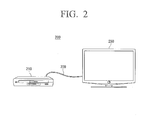
- FIG. 2 is a view illustrating an example of a display system.
- a display system comprises an external apparatus 210, interface 220, and a display apparatus 230.
- the display apparatus 230 may be connected to the external apparatus 210 through the interface 220.
- the interface 220 may be analog interface 220 such as a composite interface, an s-video interface, and a component interface.
- the external apparatus 210 may include a set-top box, a digital versatile disk player (DVDP), or a Blu-ray disk player.
- DVDP digital versatile disk player
- the display apparatus 230 may adjust the received image for an image received from the display apparatus 230 through the analog interface 220 as a 3D image.
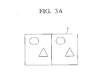
- FIGS. 3A to 3D are views to explain the image processing operation of the display apparatus.
- the display unit 160 may display a frame image (A) including a left eye image and a right eye image as illustrated in FIG. 3A .
- the left eye image is the same as the right eye image.
- the display unit 160 may display a reference pattern (B) as illustrated in FIG. 3B .
- the left eye image and the right eye image display the same image in order to display a 3D image.
- the display unit 160 may display that there is an inconsistency (i.e., a mismatching) in a pop-up window.
- the display unit 160 may display that there is an inconsistency in a received image and a message for asking whether to perform an adjustment in a pop-up window.
- the frame image (A) and the reference pattern (B) may be displayed as being overlapped with each other as illustrated in FIG. 3C .
- the image processing unit 130 may adjust the image into an image without the inconsistency by changing the size of the frame image (A) to be consistent with a reference pattern as illustrated in FIG. 3D .
- the display apparatus 100 may display an image as a 3D image.
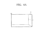
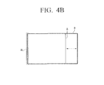
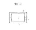
- FIGS. 4A to 4C are views illustrating examples of various frame images having at least one type of inconsistency.
- the display unit 160 may display a frame image (A) of which a length and a width are shorter than a reference pattern (B).
- a user may adjust the frame image (A) to be consistent with the reference pattern (B) using a manipulation panel or an up-down-left-right scaling button formed on one portion of the display unit 160.
- the user may define an area by moving an outline of a desired scaled frame image using the manipulation panel or the up-down-left-right scaling button formed on one portion of the display unit 160.
- the image processing unit 130 may calculate the degree of inconsistency between the frame image (A) and the scaled frame image and perform scaling on the frame image (A) to match the size and/or position of the scaled framed image.
- the image processing unit 130 may perform scaling on the frame image (A) in a left and right direction or in an up and down direction with respect to a reference point (RP), using an RP included in or extracted from sync information.
- RP reference point
- the user may define an area by moving an outline of a desired scaled frame image using the manipulation panel or the up-down-left-right scaling button formed on one portion of the display unit 160.
- the display unit 160 may display a frame image (A) of which a width is shorter than a reference pattern (B).
- a user may adjust the frame image (A) to be consistent with the reference pattern (B) using a manipulation panel or a left and right scaling button formed on one portion of the display unit 160.
- the image processing unit 130 may calculate the degree of inconsistency between the frame image (A) and a scaled frame image and perform scaling on the frame image (A) to match the size and/or position of the scaled framed image.
- the image processing unit 130 may perform scaling on the frame image (A) in a left and right direction with respect to a reference line (RL) using an RL included in or extracted from sync information.
- the display unit 160 may display a frame image (A) included in the inside of a reference pattern (B).
- a user may adjust the frame image (A) to be consistent with the reference pattern (B) using a manipulation panel or an up-down-left-right scaling button formed on one portion of the display unit 160.
- the user may define an area by moving an outline of a desired scaled frame image using the manipulation panel or the up-down-left-right scaling button formed on one portion of the display unit 160.
- a user may adjust the frame image (A) to be consistent with the reference pattern (B) using a location movement button and an up-down-left-right scaling button formed on one portion of the display unit 160.
- the image processing unit 130 may calculate the degree of inconsistency between the frame image (A) and a scaled frame image and perform scaling on the frame image (A) to match the size and/or position of the scaled framed image.
- the image processing unit 130 may perform scaling on the frame image (A) in a left and right direction or in an up and down direction with respect to a reference point (RP), using an RP included in or extracted from sync information.
- RP reference point
- the frame image (A) is not divided into a left eye image and a right eye image for convenience of explanation.
- FIGS. 4A to 4C illustrate an example of various inconsistencies where the frame image (A) is smaller than the reference pattern (B), but this is only an example.
- the present invention is not limited thereto.
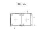
- FIGS. 5A to 5C are views illustrating examples of performing image processing using a test pattern.
- the display unit 160 may display a test pattern (T) having the same sync as a frame image.
- the test pattern of a left eye image (TL) may include a cross mark at its center and a small-sized quadrangle at each corner.
- the test pattern of a left eye image (TL) is the same as the test pattern of a right eye image (TR).
- the display unit 160 may display a test pattern (T) along with a reference pattern (B).
- the test pattern (T) may be overlapped with the reference pattern (B).
- the display unit 160 may display a test pattern of which length and width are extended in comparison with the reference pattern (B).
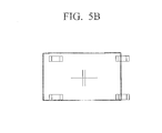
- the display unit 160 may display the processed test pattern along with the reference pattern (B) as illustrated in FIG. 5B .
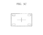
- a user may adjust a changed test pattern to be consistent with the reference pattern (B) using at least one of a manipulation panel, a location movement button and an up-down-left-right scaling button formed on one portion of the display unit 160, as shown in FIG. 5C .
- the image processing unit 130 may calculate the degree of inconsistency between the test pattern (T) and the changed test pattern and perform scaling on the frame image (A) according to the parameters of the changed test pattern.
- test pattern is not limited to the above illustration.
- FIG. 6 is a flowchart illustrating the image processing method of a display apparatus according to an exemplary embodiment.
- the receiving unit 110 receives a frame image, including the first image and the second image, and the sync information of the frame image (S610).
- the determination unit 120 determines whether the frame image is consistent with a reference pattern using the sync information (S620).
- the image processing unit 130 adjusts the frame image based on the level of inconsistency (S630).
- the image processing method of a display apparatus may further include displaying a test pattern having the same sync as a frame image along with a reference pattern.
- the image processing method of a display apparatus may further include receiving a user's command to adjust for an inconsistency.
- the image processing method of a display apparatus may further include converting the first image and the second image, and displaying the converted first and second images along with a reference pattern.
Landscapes
- Engineering & Computer Science (AREA)
- Multimedia (AREA)
- Signal Processing (AREA)
- Testing, Inspecting, Measuring Of Stereoscopic Televisions And Televisions (AREA)
- Controls And Circuits For Display Device (AREA)
- Television Systems (AREA)
Applications Claiming Priority (1)
| Application Number | Priority Date | Filing Date | Title |
|---|---|---|---|
| KR1020100091651A KR20120029690A (ko) | 2010-09-17 | 2010-09-17 | 디스플레이 장치 및 그 영상 처리 방법 |
Publications (2)
| Publication Number | Publication Date |
|---|---|
| EP2432235A2 true EP2432235A2 (de) | 2012-03-21 |
| EP2432235A3 EP2432235A3 (de) | 2013-09-04 |
Family
ID=44674304
Family Applications (1)
| Application Number | Title | Priority Date | Filing Date |
|---|---|---|---|
| EP11178466.6A Withdrawn EP2432235A3 (de) | 2010-09-17 | 2011-08-23 | Anzeigevorrichtung und Verfahren zur Bildbearbeitung dafür |
Country Status (3)
| Country | Link |
|---|---|
| US (1) | US9253477B2 (de) |
| EP (1) | EP2432235A3 (de) |
| KR (1) | KR20120029690A (de) |
Families Citing this family (3)
| Publication number | Priority date | Publication date | Assignee | Title |
|---|---|---|---|---|
| US10310668B2 (en) * | 2016-01-18 | 2019-06-04 | Coretronic Corporation | Touch screen display system and a method for controlling a touch screen display system |
| US11215828B1 (en) * | 2018-08-03 | 2022-01-04 | Rockwell Collins, Inc. | In field visor characterization for visor projected displays |
| EP4366600A4 (de) * | 2021-07-07 | 2025-05-28 | Warby Parker Inc. | Systeme und verfahren für sichttest und verwendungen davon |
Family Cites Families (9)
| Publication number | Priority date | Publication date | Assignee | Title |
|---|---|---|---|---|
| JP2861333B2 (ja) | 1990-08-29 | 1999-02-24 | 松下電器産業株式会社 | 画像補正装置 |
| US5446492A (en) * | 1993-01-19 | 1995-08-29 | Wolf; Stephen | Perception-based video quality measurement system |
| US5856843A (en) * | 1994-04-26 | 1999-01-05 | Canon Kabushiki Kaisha | Stereoscopic display method and apparatus |
| US5880883A (en) | 1994-12-07 | 1999-03-09 | Canon Kabushiki Kaisha | Apparatus for displaying image recognized by observer as stereoscopic image, and image pick-up apparatus |
| US20040218269A1 (en) * | 2002-01-14 | 2004-11-04 | Divelbiss Adam W. | General purpose stereoscopic 3D format conversion system and method |
| WO2004066203A2 (en) | 2003-01-16 | 2004-08-05 | Vrex, Inc. | A general purpose stereoscopic 3d format conversion system and method |
| US8094196B2 (en) * | 2005-07-11 | 2012-01-10 | Nippon Telegraph And Telephone Corporation | Video matching device, method, and program |
| US7538876B2 (en) | 2006-06-12 | 2009-05-26 | The Boeing Company | Efficient and accurate alignment of stereoscopic displays |
| WO2010134316A1 (ja) * | 2009-05-19 | 2010-11-25 | パナソニック株式会社 | 記録媒体、再生装置、符号化装置、集積回路、及び再生出力装置 |
-
2010
- 2010-09-17 KR KR1020100091651A patent/KR20120029690A/ko not_active Ceased
-
2011
- 2011-07-22 US US13/188,863 patent/US9253477B2/en not_active Expired - Fee Related
- 2011-08-23 EP EP11178466.6A patent/EP2432235A3/de not_active Withdrawn
Non-Patent Citations (1)
| Title |
|---|
| ANONYMOUS: "User's Guide Model. W240S Multi Function 2D/3D Wide Monitor", 21 May 2010 (2010-05-21), XP055286848, Retrieved from the Internet <URL:http://www.manualmonitor.com/manuals/hyundai/Hyundai_W240S.pdf> [retrieved on 20160707] * |
Also Published As
| Publication number | Publication date |
|---|---|
| US9253477B2 (en) | 2016-02-02 |
| US20120069155A1 (en) | 2012-03-22 |
| KR20120029690A (ko) | 2012-03-27 |
| EP2432235A3 (de) | 2013-09-04 |
Similar Documents
| Publication | Publication Date | Title |
|---|---|---|
| US9307224B2 (en) | GUI providing method, and display apparatus and 3D image providing system using the same | |
| KR101435594B1 (ko) | 디스플레이 장치 및 그 디스플레이 방법 | |
| US9414041B2 (en) | Method for changing play mode, method for changing display mode, and display apparatus and 3D image providing system using the same | |
| US20150350626A1 (en) | Method for providing three-dimensional (3d) image, method for converting 3d message, graphical user interface (gui) providing method related to 3d image, and 3d display apparatus and system for providing 3d image | |
| US20110126160A1 (en) | Method of providing 3d image and 3d display apparatus using the same | |
| EP2378783A1 (de) | 3D-Anzeigevorrichtung, Verfahren zum Einstellen des Anzeigemodus und 3D-Anzeigesystem | |
| JP2012244571A (ja) | 立体映像表示装置 | |
| KR20120066891A (ko) | 디스플레이 장치 및 그의 영상 처리 방법 | |
| JP2014011804A (ja) | ディスプレイ装置及びその制御方法 | |
| US9253477B2 (en) | Display apparatus and method for processing image thereof | |
| KR101648864B1 (ko) | 3d 영상에 대한 gui 제공방법 및 이를 이용한 디스플레이 장치 및 3d 영상 제공 시스템 | |
| JP5036088B2 (ja) | 立体画像処理装置、立体画像処理方法およびプログラム | |
| US20110141247A1 (en) | Display device and display method thereof | |
| JP2014207492A (ja) | 立体映像表示装置 | |
| EP2421271B1 (de) | Anzeigevorrichtung und Verfahren zur Anwendung auf der Bildschirmanzeige davon | |
| KR20110062983A (ko) | 3d 영상의 입체감 조절 요소를 설정하는 gui를 표시하는 디스플레이 장치 및 이에 적용되는 gui 제공 방법 | |
| KR101713786B1 (ko) | 디스플레이 장치 및 이에 적용되는 gui 제공 방법 | |
| JP5501150B2 (ja) | 表示装置及びその制御方法 | |
| KR20130056703A (ko) | 디스플레이 장치 및 그 디스플레이 방법 | |
| JP2014225736A (ja) | 画像処理装置 | |
| KR20110057948A (ko) | 디스플레이 장치, 3d 영상 제공 방법 및 3d 영상 제공 시스템 | |
| KR20110057950A (ko) | 디스플레이 장치 및 이에 적용되는 3d 영상 변환 방법, 그리고 3d 영상 제공 시스템 |
Legal Events
| Date | Code | Title | Description |
|---|---|---|---|
| PUAI | Public reference made under article 153(3) epc to a published international application that has entered the european phase |
Free format text: ORIGINAL CODE: 0009012 |
|
| AK | Designated contracting states |
Kind code of ref document: A2 Designated state(s): AL AT BE BG CH CY CZ DE DK EE ES FI FR GB GR HR HU IE IS IT LI LT LU LV MC MK MT NL NO PL PT RO RS SE SI SK SM TR |
|
| AX | Request for extension of the european patent |
Extension state: BA ME |
|
| RAP1 | Party data changed (applicant data changed or rights of an application transferred) |
Owner name: SAMSUNG ELECTRONICS CO., LTD. |
|
| PUAL | Search report despatched |
Free format text: ORIGINAL CODE: 0009013 |
|
| AK | Designated contracting states |
Kind code of ref document: A3 Designated state(s): AL AT BE BG CH CY CZ DE DK EE ES FI FR GB GR HR HU IE IS IT LI LT LU LV MC MK MT NL NO PL PT RO RS SE SI SK SM TR |
|
| AX | Request for extension of the european patent |
Extension state: BA ME |
|
| RIC1 | Information provided on ipc code assigned before grant |
Ipc: H04N 13/00 20060101AFI20130731BHEP Ipc: H04N 13/04 20060101ALI20130731BHEP |
|
| 17P | Request for examination filed |
Effective date: 20140304 |
|
| RBV | Designated contracting states (corrected) |
Designated state(s): AL AT BE BG CH CY CZ DE DK EE ES FI FR GB GR HR HU IE IS IT LI LT LU LV MC MK MT NL NO PL PT RO RS SE SI SK SM TR |
|
| 17Q | First examination report despatched |
Effective date: 20160714 |
|
| STAA | Information on the status of an ep patent application or granted ep patent |
Free format text: STATUS: THE APPLICATION IS DEEMED TO BE WITHDRAWN |
|
| 18D | Application deemed to be withdrawn |
Effective date: 20161125 |