EP2431679A2 - System zur Raumbelüftung - Google Patents
System zur Raumbelüftung Download PDFInfo
- Publication number
- EP2431679A2 EP2431679A2 EP11004367A EP11004367A EP2431679A2 EP 2431679 A2 EP2431679 A2 EP 2431679A2 EP 11004367 A EP11004367 A EP 11004367A EP 11004367 A EP11004367 A EP 11004367A EP 2431679 A2 EP2431679 A2 EP 2431679A2
- Authority
- EP
- European Patent Office
- Prior art keywords
- room
- window
- air duct
- supply air
- exhaust
- Prior art date
- Legal status (The legal status is an assumption and is not a legal conclusion. Google has not performed a legal analysis and makes no representation as to the accuracy of the status listed.)
- Granted
Links
Images


Classifications
-
- F—MECHANICAL ENGINEERING; LIGHTING; HEATING; WEAPONS; BLASTING
- F24—HEATING; RANGES; VENTILATING
- F24F—AIR-CONDITIONING; AIR-HUMIDIFICATION; VENTILATION; USE OF AIR CURRENTS FOR SCREENING
- F24F13/00—Details common to, or for air-conditioning, air-humidification, ventilation or use of air currents for screening
- F24F13/08—Air-flow control members, e.g. louvres, grilles, flaps or guide plates
- F24F13/18—Air-flow control members, e.g. louvres, grilles, flaps or guide plates specially adapted for insertion in flat panels, e.g. in door or window-pane
-
- E—FIXED CONSTRUCTIONS
- E06—DOORS, WINDOWS, SHUTTERS, OR ROLLER BLINDS IN GENERAL; LADDERS
- E06B—FIXED OR MOVABLE CLOSURES FOR OPENINGS IN BUILDINGS, VEHICLES, FENCES OR LIKE ENCLOSURES IN GENERAL, e.g. DOORS, WINDOWS, BLINDS, GATES
- E06B7/00—Special arrangements or measures in connection with doors or windows
- E06B7/02—Special arrangements or measures in connection with doors or windows for providing ventilation, e.g. through double windows; Arrangement of ventilation roses
- E06B7/10—Special arrangements or measures in connection with doors or windows for providing ventilation, e.g. through double windows; Arrangement of ventilation roses by special construction of the frame members
-
- F—MECHANICAL ENGINEERING; LIGHTING; HEATING; WEAPONS; BLASTING
- F24—HEATING; RANGES; VENTILATING
- F24F—AIR-CONDITIONING; AIR-HUMIDIFICATION; VENTILATION; USE OF AIR CURRENTS FOR SCREENING
- F24F12/00—Use of energy recovery systems in air conditioning, ventilation or screening
- F24F12/001—Use of energy recovery systems in air conditioning, ventilation or screening with heat-exchange between supplied and exhausted air
- F24F12/006—Use of energy recovery systems in air conditioning, ventilation or screening with heat-exchange between supplied and exhausted air using an air-to-air heat exchanger
-
- F—MECHANICAL ENGINEERING; LIGHTING; HEATING; WEAPONS; BLASTING
- F24—HEATING; RANGES; VENTILATING
- F24F—AIR-CONDITIONING; AIR-HUMIDIFICATION; VENTILATION; USE OF AIR CURRENTS FOR SCREENING
- F24F3/00—Air-conditioning systems in which conditioned primary air is supplied from one or more central stations to distributing units in the rooms or spaces where it may receive secondary treatment; Apparatus specially designed for such systems
- F24F3/12—Air-conditioning systems in which conditioned primary air is supplied from one or more central stations to distributing units in the rooms or spaces where it may receive secondary treatment; Apparatus specially designed for such systems characterised by the treatment of the air otherwise than by heating and cooling
- F24F3/14—Air-conditioning systems in which conditioned primary air is supplied from one or more central stations to distributing units in the rooms or spaces where it may receive secondary treatment; Apparatus specially designed for such systems characterised by the treatment of the air otherwise than by heating and cooling by humidification; by dehumidification
- F24F3/147—Air-conditioning systems in which conditioned primary air is supplied from one or more central stations to distributing units in the rooms or spaces where it may receive secondary treatment; Apparatus specially designed for such systems characterised by the treatment of the air otherwise than by heating and cooling by humidification; by dehumidification with both heat and humidity transfer between supplied and exhausted air
-
- Y—GENERAL TAGGING OF NEW TECHNOLOGICAL DEVELOPMENTS; GENERAL TAGGING OF CROSS-SECTIONAL TECHNOLOGIES SPANNING OVER SEVERAL SECTIONS OF THE IPC; TECHNICAL SUBJECTS COVERED BY FORMER USPC CROSS-REFERENCE ART COLLECTIONS [XRACs] AND DIGESTS
- Y02—TECHNOLOGIES OR APPLICATIONS FOR MITIGATION OR ADAPTATION AGAINST CLIMATE CHANGE
- Y02B—CLIMATE CHANGE MITIGATION TECHNOLOGIES RELATED TO BUILDINGS, e.g. HOUSING, HOUSE APPLIANCES OR RELATED END-USER APPLICATIONS
- Y02B30/00—Energy efficient heating, ventilation or air conditioning [HVAC]
- Y02B30/56—Heat recovery units
Definitions
- the invention relates to a system for room ventilation with a ventilation device having a supply air duct, an exhaust duct and a heat exchanger.
- Such room devices are not unknown from the prior art. They are usually either fitted into existing window openings or mounted independently of the window opening on the inside of the room.
- these prior art embodiments of a room unit are not free from disadvantages.
- the fitting of a room unit in an existing window opening is disadvantageous in that it requires different device designs and dimensions due to the different window dimensions, constructions and wall thicknesses.
- the device adaptation to existing window openings is therefore highly complex and not least costly.
- the alternative design of the space inside mounted room unit makes the formation of holes or openings through the outer wall of the building required so as to allow the desired air exchange can.
- this embodiment is also disadvantageous for aesthetic reasons, since the ventilation grille, which serve the outside closure of the ventilation pipes or channels, are clearly visible from the outside. Incidentally, these grids can only be mounted from the outside, which requires complicated scaffolding work in buildings with several storeys. In this respect too, this prior art embodiment of room units is disadvantageous.
- the invention proposes a system for room ventilation, with a ventilation unit, the supply air duct, an exhaust duct and a heat exchanger, wherein the heat exchanger is arranged inside the room and the supply air duct and the exhaust duct are guided by a window opening formed in a room wall.
- the system according to the invention has a ventilation device in the design of a room unit.
- This device has a supply air duct, an exhaust duct and a heat exchanger.
- the ventilation unit is mounted inside the room, for example on a wall.
- a ceiling or floor installation is of course also possible.
- the decisive difference from the known prior art is that there is no fitting of the device in a window opening, ie the device is not inserted into the window opening. Elaborate fitting and fitting work can therefore be advantageously avoided with the system according to the invention. Rather, it is instead possible to use standardized designs, as it does not depend on the size ratio between the device on the one hand and window opening on the other hand.
- the supply air duct and the exhaust duct are guided according to the invention by a window opening formed in a room wall.
- a window opening formed in a room wall.
- no separately be formed wall openings are provided for the supply air duct and the exhaust duct.
- an already provided window opening is used to connect the supply air and exhaust air ducts, which are connected to the heat exchanger of the ventilation unit, to the outside atmosphere by guiding the ducts through the window opening. It is also possible to use standard designs with regard to these channels, which is why the installation and intended installation of a ventilation device according to the invention can be carried out in a simple manner.
- the ventilation device is aligned window opening close.
- “Fensterö Stammsnah” means that the ventilation device is as close as possible, that is, as close as is permitted by the structural conditions, is arranged on the window opening to design the length of the supply air duct and the exhaust duct as short as possible.
- the ventilation device can be arranged wall mounted directly below a window opening.
- the supply air duct and the exhaust duct can in this case, for example, from the device coming indoors room along the room wall to be guided.
- Directly below the window inner the channels are angled in the direction of the window opening and passed below the window frame, that is, between the window frame and window reveal through the window opening.
- An orientation of the ventilation device side of a window opening or above such a window is of course also possible.
- the exhaust air duct and the supply air duct are guided in a frame broadening for the window, that is, are integrated in this frame widening. This allows an almost invisible duct installation.
- the outside openings of supply air duct and exhaust duct are closed in a manner known from the prior art by means of a grid.
- the inventive design allows such an orientation of the exhaust duct and supply air duct, that a cover of the air grille takes place through the outer window sill.
- the inventive design proves to be advantageous also from the aesthetic point of view.
- the exhaust duct and the supply air duct are accessible according to the embodiment of the invention in an advantageous manner from the room side, which simplifies the maintenance and care over the prior art.
- a proper air grille installation can be carried out from the room side, which can avoid complex scaffolding in the case of a multi-storey building.
- the system according to the invention further comprises a fan.
- this fan is preferably arranged on the outside of the room. It can be used, for example, in the supply air duct or the exhaust air duct or located at the end thereof. It can also be two fans, that is per channel fan provided.
- the heat exchanger is designed according to a further feature of the invention as Enthalpieleyer which not only allows heat exchange but also a moisture exchange.
- Enthalpieleyer which not only allows heat exchange but also a moisture exchange.
- moisture is formed by condensation during the cooling of the warm room air at the exchanger surfaces. This is transferred by means of the enthalpy exchanger to the incoming fresh air.
- This moisture exchange is advantageous in that drying out of the room air is prevented, which is a problem, especially in the cold season, because the fresh air flowing in from outside dries out when heated in the exchanger.
- the exchanger material present in the enthalpy exchanger is preferably antibacterial, so that the passage of bacteria, microbes and other pathogens is prevented. This embodiment is advantageous in that the spread of disease through the ventilation system is prevented.
- the invention further proposes a ventilation device for use in a system of the type described above.
- This ventilation device causes already vorerläuterten by the system advantages.
- FIGS. 1 to 5 an inventive system 1 for room ventilation is shown in different embodiments. This concerns the FIGS. 1 and 2 a first embodiment, the FIGS. 3 and 4 a second embodiment as well Fig. 5 a third embodiment.
- the system 1 according to the invention has a ventilation device 2, which is mounted on the interior side of the room wall 20.
- the embodiment according to the FIGS. 1 and 4 shows an embodiment according to which the ventilation device 2 below the window opening 12, that is arranged between the window opening 12 and a floor, not shown.
- the embodiment according to Fig. 5 shows an embodiment, according to the ventilation device 2 laterally, with respect to the plane of the drawing Fig. 5 is arranged left of the window opening 12.
- the room wall 20 is formed in the illustrated embodiment by a masonry 17, the outer space side carries an outer facade 18, for example in the form of a thermal insulation system.
- a window opening 12 is introduced in the room wall 20 in the room wall 20, a window opening 12 is introduced.
- this window opening 12 is an unspecified window, which provides a window frame 13 and a window pane 16 in a conventional manner.
- the window frame 13 is formed in the illustrated embodiment of a fixed and connected to the masonry 17 outer frame 14 and an outer frame 14 relatively pivotable inner frame 15.
- the inner frame 15 carries the window pane 16, as can be seen in particular from the illustration according to the FIGS. 2 . 4 and 5 results.
- an inner sill 11 and an outer sill 10 are provided in a manner known per se from the prior art.
- the trained as a room unit ventilation unit 2 has a in the Fign. only schematically illustrated heat exchanger 3, preferably in one corresponding and in Figs. Housing not shown is housed.
- the heat exchanger 3 is connected to a supply air duct 4 and an exhaust duct 5, which have a rectangular cross-section in the embodiment shown. Other cross-sectional shapes are conceivable, such as an oval or circular cross-section.
- the heat exchanger 3 is preferably designed as an enthalpy exchanger, which not only allows a heat transfer but also a moisture transfer from the used, warm room air to the newly introduced fresh air. In an advantageous manner, the dehydration of the air in the room can be prevented. Especially on cold winter days, this embodiment proves to be advantageous.
- the exchanger unit is preferably equipped with a exchanger material which is equipped with antibacterial properties.
- the transmission of bacteria, microbes and / or other pathogens by the system according to the invention can thus be prevented.
- the antibacterial finish can for example be given by the fact that the exchange material is surface-coated with a corresponding antibacterial substance.
- Antibacterial substances can also be introduced into the exchanger material.
- a fan 6 is connected to the exhaust duct 5.
- the suction 8 exhaust air and discharged through the exhaust duct 5 to the outside.
- fresh air flows through the supply air duct 4, heat exchange between supply air and exhaust air taking place in the heat exchanger 3.
- the supply air duct 4 and the exhaust duct 5 are closed by a grid 9, which in the embodiment shown in the FIGS. 1 to 4 covered by the outer sill 10 in an advantageous manner.
- the supply air duct 4 and the exhaust duct 5 are passed through the window opening 12.
- the heat exchanger 3 is arranged in the immediate vicinity of the window opening 12, which is why the channels 4 and 5 can be made relatively short.
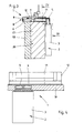
- FIGS. 1 and 2 shows an embodiment according to which the channels 4 and 5 are introduced into an unspecified frame widening.
- the frame widening extends in the gap between the reference to the drawing plane Fig. 2 lower spar of the outer frame 14 and the inner sill 11th
- FIGS. 3 and 4 shows a construction according to which the channels 4 and 5 are laid below the inner sill 11, wherein the inner sill 11 is supported by a support 19, for example a plastic insert.
Landscapes
- Engineering & Computer Science (AREA)
- Chemical & Material Sciences (AREA)
- Combustion & Propulsion (AREA)
- Mechanical Engineering (AREA)
- General Engineering & Computer Science (AREA)
- Civil Engineering (AREA)
- Structural Engineering (AREA)
- Ventilation (AREA)
- Specific Sealing Or Ventilating Devices For Doors And Windows (AREA)
- Building Environments (AREA)
- Central Air Conditioning (AREA)
Abstract
Description
- Die Erfindung betrifft ein System zur Raumbelüftung mit einem Lüftungsgerät, das einen Zuluftkanal, einen Abluftkanal und einen Wärmetauscher aufweist.
- Systeme zur Raumbelüftung im Allgemeinen sowie Lüftungsgeräte zur Raumbelüftung im Speziellen sind aus dem Stand der Technik an sich bekannt, weshalb es eines gesonderten druckschriftlichen Nachweises an dieser Stelle nicht bedarf.
- Obgleich sich vorbekannte Systeme sowie Lüftungsgeräte zur Raumbelüftung im alltäglichen Praxiseinsatz bewährt haben, besteht Verbesserungsbedarf, insbesondere mit Blick auf eine Verwendung im Sanierungs-, das heißt Modernisierungsbau.
- Die häufigste Modernisierungsmaßnahme an bestehenden Bauten ist der Ersatz der Fenster, weil diese für Schallschutz, thermischen Komfort und Wärmebedarf kostengünstig große Verbesserungen bringen. Vor dem Fensteraustausch durch Fensterfugen hinreichend gut belüftete Räume werden durch den Fensteraustausch aber sehr viel besser luftdicht abgeschlossen, was eine Belüftung der Räumlichkeiten durch regelmäßiges Öffnen der Fenster erforderlich macht, weil es ansonsten zu ungewollten Feuchtigkeitsschäden kommen kann. Derlei Feuchtigkeitsschäden können nur durch eine automatisch arbeitende Raumbelüftung zuverlässig vermieden werden. In diesem Zusammenhang ist es zur weiteren Reduktion des Wärmebedarfs zudem wünschenswert, mit einem Wärmetauscher die in der Abluft enthaltene Wärme auf die Zuluft zu übertragen. Dies wird üblicherweise mit zentralen Lüftungsgeräten erreicht, wobei in der Regel pro Wohneinheit ein zentrales Lüftungsgerät vorgesehen ist. Über entsprechende Kanal- oder Rohrleitungen sind die Räume der Wohneinheit an das zentrale Lüftungsgerät angeschlossen.
- Die nachträgliche Installation eines zentralen Lüftungsgerätes ist nicht immer möglich, in jedem Fall aber aufwendig und kostenintensiv, da ausgehend vom zentralen Lüftungsgerät in jedem Raum einer Wohneinheit entsprechend dimensionierte Rohre bzw. Kanäle zu verlegen sind. Es besteht insofern ein Bedarf an Raumgeräten, die keiner Verbindung mit einem zentralen Lüftungsgerät bedürfen.
- Derartige Raumgeräte sind aus dem Stand der Technik nicht unbekannt. Sie werden üblicherweise entweder in bestehende Fensteröffnungen eingepasst oder von der Fensteröffnung unabhängig rauminnenseitig montiert. Diese vorbekannten Ausführungsformen eines Raumgerätes sind aber nicht frei von Nachteilen. So ist die Einpassung eines Raumgerätes in eine bestehende Fensteröffnung insofern von Nachteil, als dass es aufgrund der unterschiedlichen Fensterabmessungen, -konstruktionen und Wandstärken unterschiedlicher Gerätekonstruktionen und -abmessungen bedarf. Die Geräteanpassung an bestehende Fensteröffnungen ist deshalb im höchsten Maße aufwendig und nicht zuletzt auch kostenintensiv. Die Ausführungsalternative des rauminnenseitig montierten Raumgerätes macht die Ausbildung von Bohrungen oder Durchbrüchen durch die Außenwand des Gebäudes erforderlich, um so den gewünschten Luftaustausch ermöglichen zu können. Diese Ausgestaltung ist aber auch aus ästhetischen Gründen von Nachteil, da die Lüftungsgitter, die dem außenseitigen Verschluss der Lüftungsrohre oder -kanäle dienen, von außen gut sichtbar sind. Diese Gitter können im Übrigen nur von außen montiert werden, was bei Gebäuden mit mehreren Stockwerken aufwendige Gerüstarbeiten erforderlich macht. Auch insofern ist diese vorbekannte Ausführungsform von Raumgeräten von Nachteil.
- Ausgehend vom Vorbeschriebenen ist es die Aufgabe der Erfindung, ein System zur Raumbelüftung vorzuschlagen, das die vorgenannten Nachteile zu überwinden hilft und die Verwendung von Standardkomponenten gestattet.
- Zur Lösung dieser Aufgabe wird mit der Erfindung vorgeschlagen ein System zur Raumbelüftung, mit einem Lüftungsgerät, das einen Zuluftkanal, eine Abluftkanal und einen Wärmetauscher aufweist, wobei der Wärmetauscher rauminnenseitig angeordnet ist und der Zuluftkanal sowie der Abluftkanal durch eine in einer Raumwand ausgebildete Fensteröffnung geführt sind.
- Das erfindungsgemäße System verfügt über ein Lüftungsgerät in der Ausgestaltung eines Raumgerätes. Dieses Gerät verfügt über einen Zuluftkanal, einen Abluftkanal und einen Wärmetauscher. Erfindungsgemäß ist dabei vorgesehen, dass das Lüftungsgerät rauminnenseitig montiert ist, beispielsweise an einer Wand. Eine Decken- oder Fußbodenmontage ist natürlich auch möglich. Der entscheidende Unterschied zum vorbekannten Stand der Technik besteht jedenfalls darin, dass keine Einpassung des Gerätes in eine Fensteröffnung erfolgt, das Gerät also nicht in die Fensteröffnung eingesetzt ist. Aufwendige An- und Einpassungsarbeiten können mit dem System nach der Erfindung deshalb in vorteilhafter Weise vermieden werden. Es ist stattdessen vielmehr möglich, standardisierte Bauformen zu verwenden, da es auf das Größenverhältnis zwischen Gerät einerseits und Fensteröffnung andererseits nicht ankommt.
- Der Zuluftkanal sowie der Abluftkanal sind erfindungsgemäß durch eine in einer Raumwand ausgebildete Fensteröffnung geführt. Anders als aus dem Stand der Technik vorbekannt, sind für den Zuluftkanal und den Abluftkanal keine separat auszubildenden Wanddurchbrüche vorgesehen. Es wird vielmehr eine ohnehin schon vorgesehene Fensteröffnung dazu genutzt, die mit dem Wärmetauscher des Lüftungsgerätes verbundene Zuluft- und Abluftkanäle mit der Außenatmosphäre zu verbinden, indem die Kanäle durch die Fensteröffnung hindurch geführt sind. Es lassen sich auch bezüglich dieser Kanäle Standardbauformen verwenden, weshalb die Installation und bestimmungsgemäße Einrichtung eines erfindungsgemäßen Lüftungsgerätes in einfacher Weise vorgenommen werden kann.
- Gemäß einer bevorzugten Ausführungsform der erfindungsgemäßen Ausgestaltung ist das Lüftungsgerät fensteröffnungsnah ausgerichtet. "Fensteröffnungsnah" bedeutet dabei, dass das Lüftungsgerät so nah wie möglich, das heißt so nah wie dies durch die baulichen Gegebenheiten gestattet ist, an der Fensteröffnung angeordnet ist, um die Länge des Zuluftkanals und des Abluftkanals so kurz wie möglich auszugestalten. Beispielsweise kann das Lüftungsgerät direkt unterhalb einer Fensteröffnung wandmontiert angeordnet sein. Der Zuluftkanal und der Abluftkanal können in diesem Fall beispielsweise vom Gerät kommend rauminnenseitig entlang der Raumwand geführt sein. Direkt unterhalb der Fensterinnenbank sind die Kanäle in Richtung auf die Fensteröffnung abgewinkelt und unterhalb des Fensterrahmens, das heißt zwischen Fensterrahmen und Fensterleibung durch die Fensteröffnung hindurchgeführt. Eine Ausrichtung des Lüftungsgerätes seitlich einer Fensteröffnung oder oberhalb einer solchen ist selbstredend auch möglich.
- Infolge des Hindurchführens der Kanäle durch die Fensteröffnung verringert sich der zur Verfügung stehende Einbauraum für ein in die Fensteröffnung einzusetzendes Fenster. Der von den Kanälen benötigte Einbauraum ist aber sehr viel kleiner als im Falle der vorbekannten Konstruktion, dergemäß Raumgeräte als solche in die Fensteröffnung eingepasst sind. Der benötigte Einbauraum für die Kanäle kann in vorteilhafter Weise zum Großteil durch moderne Fensterrahmenkonstruktionen der neuesten Generation ausgeglichen werden, die im Unterschied zu Altkonstruktionen, wie sie häufig in Sanierungsobjekten anzutreffen sind, sehr viel weniger volumig sind.
- Es kann gemäß einem weiteren Merkmal der Erfindung vorgesehen sein, dass der Abluftkanal und der Zuluftkanal in einer Rahmenverbreiterung für das Fenster geführt sind, das heißt in dieser Rahmenverbreiterung integriert sind. Dies ermöglicht eine nahezu unsichtbare Kanalinstallation.
- Die außenseitigen Öffnungen von Zuluftkanal und Abluftkanal sind in an sich aus dem Stand der Technik bekannter Weise mittels eines Gitters verschlossen. Dabei ermöglicht die erfindungsgemäße Ausgestaltung eine solche Ausrichtung von Abluftkanal und Zuluftkanal, dass eine Abdeckung der Luftgitter durch das außenliegende Fensterbrett erfolgt. Anders als aus dem Stand der Technik vorbekannte Konstruktionen erweist sich die erfindungsgemäße Ausgestaltung insofern auch unter dem ästhetischen Gesichtspunkt als vorteilhaft.
- Der Abluftkanal sowie der Zuluftkanal sind nach der erfindungsgemäßen Ausgestaltung in vorteilhafter Weise von der Raumseite zugänglich, was die Wartung und Pflege gegenüber dem Stand der Technik vereinfacht. Im Übrigen kann eine bestimmungsgemäße Luftgitterinstallation von der Raumseite her durchgeführt werden, was im Falle eines mehrgeschossigen Gebäudes aufwendige Gerüstarbeiten vermeiden lässt.
- Das erfindungsgemäße System umfasst des Weiteren einen Ventilator. Dieser Ventilator ist aus Gründen der Geräuschdämmung vorzugsweise raumaußenseitig angeordnet. Er kann beispielsweise in den Zuluftkanal oder den Abluftkanal eingesetzt sein oder sich endseitig desselben befinden. Es können auch zwei Ventilatoren, das heißt je Kanal ein Ventilator vorgesehen sein.
- Der Wärmetauscher ist gemäß einem weiteren Merkmal der Erfindung als Enthalpietauscher ausgebildet, der nicht nur einen Wärmeaustausch sondern auch einen Feuchtigkeitsaustausch ermöglicht. Infolge des Wärmeaustausches entsteht bei der Abkühlung der warmen Raumluft an den Tauscherflächen Feuchtigkeit durch Kondensation. Diese wird mittels des Enthalpietauschers an die einströmende Frischluft übertragen. Es findet insofern nicht nur ein Wärmeübergang von der verbrauchten Raumluft auf die einströmende Frischluft sondern auch eine Feuchtigkeitsübermittlung von der Raumluft auf die Frischluft statt. Dieser Feuchtigkeitsaustausch ist insofern von Vorteil, als dass ein Austrocknen der Raumluft verhindert wird, was insbesondere in der kalten Jahreszeit ein Problem darstellt, weil die von außen einströmende kalte Frischluft beim Erwärmen im Tauscher austrocknet.
- Das im Enthalpietauscher vorhandene Tauschermaterial ist bevorzugter Weise antibakteriell ausgerüstet, so dass der Durchgang von Bakterien, Mikroben und anderen Erregern verhindert ist. Diese Ausgestaltung ist insofern von Vorteil, als dass die Ausbreitung von Krankheiten über das Lüftungssystem verhindert wird.
- Mit der Erfindung wird des Weiteren ein Lüftungsgerät zur Verwendung in einem System der vorbeschriebenen Art vorgeschlagen. Dieses Lüftungsgerät bewirkt die schon anhand des Systems vorerläuterten Vorteile.
- Weitere Vorteile und Merkmale der Erfindung ergeben sich aus der nachfolgenden Beschreibung anhand der Fign. Dabei zeigen
-
Fig. 1 in schematischer Seitenansicht ein efindungsgemäßes System gemäß einer ersten Ausführungsform; -
Fig. 2 das System nachFig. 1 gemäß Schnittlinie II-II nachFig. 1 ; -
Fig.3 in schematischer Seitenansicht ein erfindungsgemäßes System gemäß einer zweiten Ausführungsform; -
Fig. 4 das System nachFig. 1 gemäß Schnittlinie IV-IV nachFig. 3 und -
Fig. 5 in schematischer Seitenansicht ein erfindungsgemäßes System gemäß einer dritten Ausführungsform. - In den
Fign. 1 bis 5 ist ein erfindungsgemäßes System 1 zur Raumbelüftung in unterschiedlichen Ausführungsformen gezeigt. Dabei betreffen dieFign. 1 und 2 eine erste Ausführungsform, dieFign. 3 und 4 eine zweite Ausführungsform sowieFig. 5 eine dritte Ausführungsform. - Das erfindungsgemäße System 1 verfügt über ein Lüftungsgerät 2, das rauminnenseitig an der Raumwand 20 montiert ist. Die Ausführungsform nach den
Fign. 1 und4 zeigt eine Ausgestaltung, dergemäß das Lüftungsgerät 2 unterhalb der Fensteröffnung 12, das heißt zwischen der Fensteröffnung 12 und einem nicht gezeigten Fußboden angeordnet ist. Das Ausführungsbeispiel nachFig. 5 zeigt eine Ausführungsform, dergemäß das Lüftungsgerät 2 seitlich, und zwar mit Bezug auf die Zeichnungsebene nachFig. 5 links der Fensteröffnung 12 angeordnet ist. - Die Raumwand 20 ist im gezeigten Ausführungsbeispiel durch ein Mauerwerk 17 gebildet, das raumaußenseitig eine Außenfassade 18, beispielsweise in Form eines Wärmedämmsystems trägt. In die Raumwand 20 ist eine Fensteröffnung 12 eingebracht. In dieser Fensteröffnung 12 befindet sich ein nicht näher bezeichnetes Fenster, das in an sich bekannter Weise einen Fensterrahmen 13 sowie eine Fensterscheibe 16 bereitstellt. Der Fensterrahmen 13 ist im gezeigten Ausführungsbeispiel aus einem feststehenden und mit dem Mauerwerk 17 verbundenen Außenrahmen 14 und einem zum Außenrahmen 14 relativ verschwenkbaren Innenrahmen 15 gebildet. Der Innenrahmen 15 trägt die Fensterscheibe 16, wie sich insbesondere aus der Darstellung nach den
Fign. 2 ,4 und5 ergibt. Es sind in an sich aus dem Stand der Technik bekannter Weise des Weiteren eine Innenfensterbank 11 sowie eine Außenfensterbank 10 vorgesehen. - Das als Raumgerät ausgebildete Lüftungsgerät 2 verfügt über einen in den Fign. nur schematisch dargestellten Wärmetauscher 3, der bevorzugterweise in einem entsprechenden und in den Fign. nicht näher dargestellten Gehäuse untergebracht ist. Der Wärmetauscher 3 ist an einen Zuluftkanal 4 und einen Abluftkanal 5 angeschlossen, die im gezeigten Ausführungsbeispiel einen rechteckförmigen Querschnitt aufweisen. Auch andere Querschnittsformen sind denkbar, so zum Beispiel ein ovaler oder kreisförmiger Querschnitt. Der Wärmetauscher 3 ist bevorzugterweise als Enthalpietauscher ausgebildet, der nicht nur einen Wärmeübergang sondern auch einen Feuchtigkeitsübergang von der verbrauchten, warmen Raumluft auf die neu eingeführte Frischluft zulässt. In vorteilhafter Weise kann so die Austrocknung der im Raum befindlichen Luft verhindert werden. Insbesondere an kalten Wintertagen erweist sich diese Ausgestaltung als vorteilhaft. Dabei ist die Tauschereinheit bevorzugterweise mit einem Tauschermaterial bestückt, das antibakteriell ausgerüstet ist. Die Übertragung von Bakterien, Mikroben und/oder anderen Krankheitserregern durch das erfindungsgemäße System kann so verhindert werden. Die antibakterielle Ausrüstung kann beispielsweise dadurch gegeben sein, dass das Tauschermaterial mit einer entsprechenden antibakteriell wirkenden Substanz oberflächenbeschichtet ist. Es können auch antibakteriell wirkende Stoffe in das Tauschermaterial eingebracht sein.
- Außenseitig ist an den Abluftkanal 5 ein Ventilator 6 angeschlossen. Im bestimmungsgemäßen Verwendungsfall wird durch diesen in Sogrichtung 8 Abluft 7 angesogen und über den Abluftkanal 5 nach außen abgegeben. Über den Zuluftkanal 4 strömt gleichzeitig Frischluft zu, wobei im Wärmetauscher 3 ein Wärmeaustausch zwischen Zuluft und Abluft erfolgt.
- Außenseitig sind der Zuluftkanal 4 und der Abluftkanal 5 durch ein Gitter 9 verschlossen, das im gezeigten Ausführungsbeispiel nach den
Fign. 1 bis 4 durch die Außenfensterbank 10 in vorteilhafter Weise abgedeckt ist. - Wie die Darstellung nach den
Fign. 1 bis 5 gut erkennen lässt, sind der Zuluftkanal 4 und der Abluftkanal 5 durch die Fensteröffnung 12 hindurchgeführt. Der Wärmetauscher 3 ist in unmittelbarer Nähe zur Fensteröffnung 12 angeordnet, weshalb die Kanäle 4 und 5 verhältnismäßig kurz ausgebildet werden können. - Das Ausführungsbeispiel nach den
Fign. 1 und 2 zeigt eine Ausgestaltung, dergemäß die Kanäle 4 und 5 in eine nicht näher bezeichnete Rahmenverbreiterung eingebracht sind. Dabei erstreckt sich die Rahmenverbreiterung im Spaltraum zwischen dem mit Bezug auf die Zeichnungsebene nachFig. 2 unteren Holm des Außenrahmens 14 und der Innenfensterbank 11. - Die Ausführungsform nach den
Fign. 3 und 4 zeigt eine Konstruktion, dergemäß die Kanäle 4 und 5 unterhalb der Innenfensterbank 11 verlegt sind, wobei die Innenfensterbank 11 von einem Träger 19, beispielsweise einem Einsatzstück aus Kunststoff gehalten bzw. getragen ist. -
- 1
- System
- 2
- Lüftungsgerät
- 3
- Wärmetauscher
- 4
- Zuluftkanal
- 5
- Abluftkanal
- 6
- Ventilator
- 7
- Abluft
- 8
- Sogrichtung
- 9
- Gitter
- 10
- Außenfensterbank
- 11
- Innenfensterbank
- 12
- Fensteröffnung
- 13
- Fensterrahmen
- 14
- Außenrahmen
- 15
- Innenrahmen
- 16
- Fensterscheibe
- 17
- Mauerwerk
- 18
- Außenfassade
- 19
- Träger
- 20
- Raumwand
Claims (12)
- System (1) zur Raumbelüftung, mit einem Lüftungsgerät (2), das einen Zuluftkanal (4), einen Abluftkanal (5) und einen Wärmetauscher (3) aufweist, wobei der Wärmetauscher (3) rauminnenseitig angeordnet ist und der Zuluftkanal (4) sowie der Abluftkanal (5) durch eine in einer Raumwand (20) ausgebildete Fensteröffnung (12) geführt sind.
- System nach Anspruch 1, dadurch gekennzeichnet, dass der Wärmetauscher (3) fensteröffnungsnah angeordnet ist.
- System nach Anspruch 1 oder 2, dadurch gekennzeichnet, dass der Zuluftkanal (4) und der Abluftkanal (5) zwischen dem die Fensteröffnung (12) begrenzenden Mauerwerk (17) und einem in die Fensteröffnung (12) eingesetzten Rahmen (13) eines Fensters hindurchgeführt sind.
- System nach einem der vorhergehenden Ansprüche, dadurch gekennzeichnet, dass der Zuluftkanal (4) und der Abluftkanal (5) in eine Verbreiterung des Fensterrahmens (13) integriert sind.
- System nach einem der vorhergehenden Ansprüche, gekennzeichnet durch einen im Zuluft- oder Abluftkanal (4, 5) angeordneten Ventilator (6).
- System nach Anspruch 5, dadurch gekennzeichnet, dass der Ventilator (6) raumaußenseitig angeordnet ist.
- System nach einem der vorhergehenden Ansprüche, dadurch gekennzeichnet, dass die raumaußenseitigen Öffnung des Zuluftkanals (4) und des Abluftkanals (5) unterhalb einer Außenfensterbank (10) ausgebildet sind.
- System nach einem der vorhergehenden Ansprüche 1 bis 6, dadurch gekennzeichnet, dass die raumaußenseitigen Öffnungen des Zuluftkanals (4) und des Abluftkanals (5) seitlich des Fensterrahmens (13) oder oberhalb des oberen Fensterrahmenholms ausgebildet sind.
- System nach einem der vorhergehenden Ansprüche, dadurch gekennzeichnet, dass die raumaußenseitigen Öffnungen des Zuluftkanals (4) des Abluftkanals (5) jeweils mit einem Gitter verschlossen sind.
- System nach einem der vorhergehenden Ansprüche, dadurch gekennzeichnet, dass der Wärmetauscher (3) ein Enthalpietauscher ist.
- System nach Anspruch 10, dadurch gekennzeichnet, dass der Enthalpietauscher ein Tauschermaterial enthält, das antibakteriell ausgerüstet ist.
- Lüftungsgerät (2) mit den Merkmalen nach einem der vorhergehenden Ansprüche 1 bis 11.
Priority Applications (1)
| Application Number | Priority Date | Filing Date | Title |
|---|---|---|---|
| EP19217910.9A EP3653947A1 (de) | 2010-09-18 | 2011-05-27 | System zur raumbelüftung |
Applications Claiming Priority (1)
| Application Number | Priority Date | Filing Date | Title |
|---|---|---|---|
| DE202010012838U DE202010012838U1 (de) | 2010-09-18 | 2010-09-18 | System zur Raumbelüftung |
Related Child Applications (2)
| Application Number | Title | Priority Date | Filing Date |
|---|---|---|---|
| EP19217910.9A Division EP3653947A1 (de) | 2010-09-18 | 2011-05-27 | System zur raumbelüftung |
| EP19217910.9A Division-Into EP3653947A1 (de) | 2010-09-18 | 2011-05-27 | System zur raumbelüftung |
Publications (3)
| Publication Number | Publication Date |
|---|---|
| EP2431679A2 true EP2431679A2 (de) | 2012-03-21 |
| EP2431679A3 EP2431679A3 (de) | 2016-04-20 |
| EP2431679B1 EP2431679B1 (de) | 2020-04-01 |
Family
ID=43299566
Family Applications (2)
| Application Number | Title | Priority Date | Filing Date |
|---|---|---|---|
| EP19217910.9A Withdrawn EP3653947A1 (de) | 2010-09-18 | 2011-05-27 | System zur raumbelüftung |
| EP11004367.6A Active EP2431679B1 (de) | 2010-09-18 | 2011-05-27 | System zur Raumbelüftung |
Family Applications Before (1)
| Application Number | Title | Priority Date | Filing Date |
|---|---|---|---|
| EP19217910.9A Withdrawn EP3653947A1 (de) | 2010-09-18 | 2011-05-27 | System zur raumbelüftung |
Country Status (2)
| Country | Link |
|---|---|
| EP (2) | EP3653947A1 (de) |
| DE (1) | DE202010012838U1 (de) |
Families Citing this family (1)
| Publication number | Priority date | Publication date | Assignee | Title |
|---|---|---|---|---|
| CN108286768A (zh) * | 2018-01-17 | 2018-07-17 | 贵州正方实业有限公司 | 一种门窗幕墙空气调节系统 |
Family Cites Families (11)
| Publication number | Priority date | Publication date | Assignee | Title |
|---|---|---|---|---|
| US5230719A (en) * | 1990-05-15 | 1993-07-27 | Erling Berner | Dehumidification apparatus |
| DE9202039U1 (de) * | 1992-02-18 | 1992-06-04 | FSL Fenster-System-Lüftung GmbH, 6800 Mannheim | Lüftungsfenster für die Räume von Gebäuden |
| DE4222987A1 (de) * | 1992-07-13 | 1994-02-24 | Rheinhold & Mahla Ag | Anordnung zur Be- und Entlüftung in Außenwandelementen |
| DE19709328C2 (de) * | 1997-03-07 | 2001-04-12 | Stiebel Eltron Gmbh & Co Kg | Luftleiteinrichtung für eine Gebäudewand |
| DE19855056C5 (de) * | 1998-11-28 | 2008-10-02 | AUMA-TEC Ausbau-, Umwelt- und Anlagen-Technik GmbH | Gerätesystem für die Lüftung von Einzelräumen |
| DE10010817A1 (de) * | 2000-03-08 | 2001-10-18 | Mig Mittelstands Entwicklungsg | Raumlüftungsvorrichtung |
| DE20204163U1 (de) * | 2002-03-14 | 2003-07-24 | Siegenia Aubi Kg | Raumlüftungsvorrichtung |
| NL1020481C1 (nl) | 2002-04-26 | 2003-10-31 | Oxycell Holding Bv | Enthalpiewisselaar, uitgevoerd als kozijnstijl. |
| KR100579373B1 (ko) * | 2003-11-24 | 2006-05-12 | 엘지전자 주식회사 | 환기장치의 열교환기에 사용되는 기능성 종이 |
| FR2924741B1 (fr) * | 2007-12-07 | 2013-03-29 | Aldes Aeraulique | Procede de fabrication d'un element vitre, module de ventilation et element vitre equipe d'un tel module |
| BE1018084A3 (nl) * | 2008-04-02 | 2010-05-04 | Parys Remi E Van | Verluchtingselement. |
-
2010
- 2010-09-18 DE DE202010012838U patent/DE202010012838U1/de not_active Expired - Lifetime
-
2011
- 2011-05-27 EP EP19217910.9A patent/EP3653947A1/de not_active Withdrawn
- 2011-05-27 EP EP11004367.6A patent/EP2431679B1/de active Active
Non-Patent Citations (1)
| Title |
|---|
| None |
Also Published As
| Publication number | Publication date |
|---|---|
| EP2431679A3 (de) | 2016-04-20 |
| DE202010012838U1 (de) | 2010-12-02 |
| EP3653947A1 (de) | 2020-05-20 |
| EP2431679B1 (de) | 2020-04-01 |
Similar Documents
| Publication | Publication Date | Title |
|---|---|---|
| EP0044560B1 (de) | Belüftungsanlage für im Zwangsumlauf belüftete Räume | |
| EP2594725B1 (de) | Fenster | |
| DE102011080358A1 (de) | Einbauprofil | |
| DE102008051032A1 (de) | Modulares und Fassaden-integriertes Lüftungs- und Klimasystem | |
| DE10010817A1 (de) | Raumlüftungsvorrichtung | |
| DE102009045668B3 (de) | Plattenförmiges Dämmelement zur Wärmedämmung von Gebäuden | |
| EP2965016B1 (de) | Aktive überströmanordnung | |
| DE102008020941A1 (de) | Lüftungselement zum Zuführen und/oder Abführen von Luft sowie Lüftungseinrichtung für eine dezentrale Schalldämmlüftung | |
| DE102013114085A1 (de) | Lüftungsgerät zur Raumlüftung | |
| EP2431679B1 (de) | System zur Raumbelüftung | |
| DE102014013261A1 (de) | Einbausystem für Fenster oder Türen | |
| DE202013105438U1 (de) | Aufnahmeelement | |
| DE102016103950B4 (de) | Anordnung zur Be- und Entlüftung von Räumen im Bereich eines Fensters | |
| DE10015581C1 (de) | Innenraum-Klimatisierungsvorrichtung | |
| DE202013010296U1 (de) | Einbausystem für Fenster oder Türen | |
| DE2915494A1 (de) | Reckuperative waermerueckgewinnung bei statischen heizungen | |
| DE9406653U1 (de) | Belüftungsprofil zum Ausrüsten von Fenster oder Türen | |
| CH701880A2 (de) | Luftführungssystem zur Belüftung von Räumen eines Gebäudes. | |
| DE102011002605A1 (de) | Dezentrale Raumlüftungsvorrichtung mit Wärmerückgewinnung | |
| DE1801852A1 (de) | Lueftungs- oder Klimaanlage | |
| DE202019004927U1 (de) | Zuluft- und Abluftvorrichtung für Klimageräte | |
| DE102014117728A1 (de) | Rahmenmodul für die Dämmung eines Gebäudes | |
| DE202016008921U1 (de) | Fensterdämmelement | |
| AT524782B1 (de) | Verschlussvorrichtung für eine Wandöffnung | |
| DE2922441A1 (de) | Hochdruckklimageraet fuer energiesparbetrieb |
Legal Events
| Date | Code | Title | Description |
|---|---|---|---|
| PUAI | Public reference made under article 153(3) epc to a published international application that has entered the european phase |
Free format text: ORIGINAL CODE: 0009012 |
|
| AK | Designated contracting states |
Kind code of ref document: A2 Designated state(s): AL AT BE BG CH CY CZ DE DK EE ES FI FR GB GR HR HU IE IS IT LI LT LU LV MC MK MT NL NO PL PT RO RS SE SI SK SM TR |
|
| AX | Request for extension of the european patent |
Extension state: BA ME |
|
| RAP1 | Party data changed (applicant data changed or rights of an application transferred) |
Owner name: ZEHNDER GROUP INTERNATIONAL AG |
|
| PUAL | Search report despatched |
Free format text: ORIGINAL CODE: 0009013 |
|
| AK | Designated contracting states |
Kind code of ref document: A3 Designated state(s): AL AT BE BG CH CY CZ DE DK EE ES FI FR GB GR HR HU IE IS IT LI LT LU LV MC MK MT NL NO PL PT RO RS SE SI SK SM TR |
|
| AX | Request for extension of the european patent |
Extension state: BA ME |
|
| RIC1 | Information provided on ipc code assigned before grant |
Ipc: F24F 12/00 20060101AFI20160316BHEP Ipc: E06B 7/10 20060101ALI20160316BHEP Ipc: F24F 13/18 20060101ALI20160316BHEP Ipc: F24F 3/147 20060101ALI20160316BHEP |
|
| 17P | Request for examination filed |
Effective date: 20161019 |
|
| RBV | Designated contracting states (corrected) |
Designated state(s): AL AT BE BG CH CY CZ DE DK EE ES FI FR GB GR HR HU IE IS IT LI LT LU LV MC MK MT NL NO PL PT RO RS SE SI SK SM TR |
|
| STAA | Information on the status of an ep patent application or granted ep patent |
Free format text: STATUS: EXAMINATION IS IN PROGRESS |
|
| 17Q | First examination report despatched |
Effective date: 20190408 |
|
| GRAP | Despatch of communication of intention to grant a patent |
Free format text: ORIGINAL CODE: EPIDOSNIGR1 |
|
| STAA | Information on the status of an ep patent application or granted ep patent |
Free format text: STATUS: GRANT OF PATENT IS INTENDED |
|
| INTG | Intention to grant announced |
Effective date: 20191122 |
|
| GRAS | Grant fee paid |
Free format text: ORIGINAL CODE: EPIDOSNIGR3 |
|
| GRAA | (expected) grant |
Free format text: ORIGINAL CODE: 0009210 |
|
| STAA | Information on the status of an ep patent application or granted ep patent |
Free format text: STATUS: THE PATENT HAS BEEN GRANTED |
|
| AK | Designated contracting states |
Kind code of ref document: B1 Designated state(s): AL AT BE BG CH CY CZ DE DK EE ES FI FR GB GR HR HU IE IS IT LI LT LU LV MC MK MT NL NO PL PT RO RS SE SI SK SM TR |
|
| REG | Reference to a national code |
Ref country code: GB Ref legal event code: FG4D Free format text: NOT ENGLISH |
|
| REG | Reference to a national code |
Ref country code: CH Ref legal event code: EP Ref country code: AT Ref legal event code: REF Ref document number: 1251847 Country of ref document: AT Kind code of ref document: T Effective date: 20200415 |
|
| REG | Reference to a national code |
Ref country code: DE Ref legal event code: R096 Ref document number: 502011016570 Country of ref document: DE |
|
| REG | Reference to a national code |
Ref country code: IE Ref legal event code: FG4D Free format text: LANGUAGE OF EP DOCUMENT: GERMAN |
|
| REG | Reference to a national code |
Ref country code: CH Ref legal event code: NV Representative=s name: DENNEMEYER AG, CH |
|
| PGFP | Annual fee paid to national office [announced via postgrant information from national office to epo] |
Ref country code: FR Payment date: 20200619 Year of fee payment: 11 |
|
| PG25 | Lapsed in a contracting state [announced via postgrant information from national office to epo] |
Ref country code: BG Free format text: LAPSE BECAUSE OF FAILURE TO SUBMIT A TRANSLATION OF THE DESCRIPTION OR TO PAY THE FEE WITHIN THE PRESCRIBED TIME-LIMIT Effective date: 20200701 |
|
| REG | Reference to a national code |
Ref country code: NL Ref legal event code: MP Effective date: 20200401 |
|
| REG | Reference to a national code |
Ref country code: LT Ref legal event code: MG4D |
|
| PG25 | Lapsed in a contracting state [announced via postgrant information from national office to epo] |
Ref country code: SE Free format text: LAPSE BECAUSE OF FAILURE TO SUBMIT A TRANSLATION OF THE DESCRIPTION OR TO PAY THE FEE WITHIN THE PRESCRIBED TIME-LIMIT Effective date: 20200401 Ref country code: NL Free format text: LAPSE BECAUSE OF FAILURE TO SUBMIT A TRANSLATION OF THE DESCRIPTION OR TO PAY THE FEE WITHIN THE PRESCRIBED TIME-LIMIT Effective date: 20200401 Ref country code: PT Free format text: LAPSE BECAUSE OF FAILURE TO SUBMIT A TRANSLATION OF THE DESCRIPTION OR TO PAY THE FEE WITHIN THE PRESCRIBED TIME-LIMIT Effective date: 20200817 Ref country code: LT Free format text: LAPSE BECAUSE OF FAILURE TO SUBMIT A TRANSLATION OF THE DESCRIPTION OR TO PAY THE FEE WITHIN THE PRESCRIBED TIME-LIMIT Effective date: 20200401 Ref country code: GR Free format text: LAPSE BECAUSE OF FAILURE TO SUBMIT A TRANSLATION OF THE DESCRIPTION OR TO PAY THE FEE WITHIN THE PRESCRIBED TIME-LIMIT Effective date: 20200702 Ref country code: CZ Free format text: LAPSE BECAUSE OF FAILURE TO SUBMIT A TRANSLATION OF THE DESCRIPTION OR TO PAY THE FEE WITHIN THE PRESCRIBED TIME-LIMIT Effective date: 20200401 Ref country code: NO Free format text: LAPSE BECAUSE OF FAILURE TO SUBMIT A TRANSLATION OF THE DESCRIPTION OR TO PAY THE FEE WITHIN THE PRESCRIBED TIME-LIMIT Effective date: 20200701 Ref country code: IS Free format text: LAPSE BECAUSE OF FAILURE TO SUBMIT A TRANSLATION OF THE DESCRIPTION OR TO PAY THE FEE WITHIN THE PRESCRIBED TIME-LIMIT Effective date: 20200801 Ref country code: FI Free format text: LAPSE BECAUSE OF FAILURE TO SUBMIT A TRANSLATION OF THE DESCRIPTION OR TO PAY THE FEE WITHIN THE PRESCRIBED TIME-LIMIT Effective date: 20200401 |
|
| PG25 | Lapsed in a contracting state [announced via postgrant information from national office to epo] |
Ref country code: LV Free format text: LAPSE BECAUSE OF FAILURE TO SUBMIT A TRANSLATION OF THE DESCRIPTION OR TO PAY THE FEE WITHIN THE PRESCRIBED TIME-LIMIT Effective date: 20200401 Ref country code: HR Free format text: LAPSE BECAUSE OF FAILURE TO SUBMIT A TRANSLATION OF THE DESCRIPTION OR TO PAY THE FEE WITHIN THE PRESCRIBED TIME-LIMIT Effective date: 20200401 Ref country code: RS Free format text: LAPSE BECAUSE OF FAILURE TO SUBMIT A TRANSLATION OF THE DESCRIPTION OR TO PAY THE FEE WITHIN THE PRESCRIBED TIME-LIMIT Effective date: 20200401 |
|
| PG25 | Lapsed in a contracting state [announced via postgrant information from national office to epo] |
Ref country code: AL Free format text: LAPSE BECAUSE OF FAILURE TO SUBMIT A TRANSLATION OF THE DESCRIPTION OR TO PAY THE FEE WITHIN THE PRESCRIBED TIME-LIMIT Effective date: 20200401 |
|
| REG | Reference to a national code |
Ref country code: DE Ref legal event code: R097 Ref document number: 502011016570 Country of ref document: DE |
|
| PG25 | Lapsed in a contracting state [announced via postgrant information from national office to epo] |
Ref country code: IT Free format text: LAPSE BECAUSE OF FAILURE TO SUBMIT A TRANSLATION OF THE DESCRIPTION OR TO PAY THE FEE WITHIN THE PRESCRIBED TIME-LIMIT Effective date: 20200401 Ref country code: RO Free format text: LAPSE BECAUSE OF FAILURE TO SUBMIT A TRANSLATION OF THE DESCRIPTION OR TO PAY THE FEE WITHIN THE PRESCRIBED TIME-LIMIT Effective date: 20200401 Ref country code: MC Free format text: LAPSE BECAUSE OF FAILURE TO SUBMIT A TRANSLATION OF THE DESCRIPTION OR TO PAY THE FEE WITHIN THE PRESCRIBED TIME-LIMIT Effective date: 20200401 Ref country code: DK Free format text: LAPSE BECAUSE OF FAILURE TO SUBMIT A TRANSLATION OF THE DESCRIPTION OR TO PAY THE FEE WITHIN THE PRESCRIBED TIME-LIMIT Effective date: 20200401 Ref country code: ES Free format text: LAPSE BECAUSE OF FAILURE TO SUBMIT A TRANSLATION OF THE DESCRIPTION OR TO PAY THE FEE WITHIN THE PRESCRIBED TIME-LIMIT Effective date: 20200401 Ref country code: SM Free format text: LAPSE BECAUSE OF FAILURE TO SUBMIT A TRANSLATION OF THE DESCRIPTION OR TO PAY THE FEE WITHIN THE PRESCRIBED TIME-LIMIT Effective date: 20200401 Ref country code: EE Free format text: LAPSE BECAUSE OF FAILURE TO SUBMIT A TRANSLATION OF THE DESCRIPTION OR TO PAY THE FEE WITHIN THE PRESCRIBED TIME-LIMIT Effective date: 20200401 |
|
| PLBE | No opposition filed within time limit |
Free format text: ORIGINAL CODE: 0009261 |
|
| STAA | Information on the status of an ep patent application or granted ep patent |
Free format text: STATUS: NO OPPOSITION FILED WITHIN TIME LIMIT |
|
| PG25 | Lapsed in a contracting state [announced via postgrant information from national office to epo] |
Ref country code: SK Free format text: LAPSE BECAUSE OF FAILURE TO SUBMIT A TRANSLATION OF THE DESCRIPTION OR TO PAY THE FEE WITHIN THE PRESCRIBED TIME-LIMIT Effective date: 20200401 Ref country code: PL Free format text: LAPSE BECAUSE OF FAILURE TO SUBMIT A TRANSLATION OF THE DESCRIPTION OR TO PAY THE FEE WITHIN THE PRESCRIBED TIME-LIMIT Effective date: 20200401 |
|
| 26N | No opposition filed |
Effective date: 20210112 |
|
| REG | Reference to a national code |
Ref country code: BE Ref legal event code: MM Effective date: 20200531 |
|
| PG25 | Lapsed in a contracting state [announced via postgrant information from national office to epo] |
Ref country code: LU Free format text: LAPSE BECAUSE OF NON-PAYMENT OF DUE FEES Effective date: 20200527 |
|
| PG25 | Lapsed in a contracting state [announced via postgrant information from national office to epo] |
Ref country code: IE Free format text: LAPSE BECAUSE OF NON-PAYMENT OF DUE FEES Effective date: 20200527 |
|
| PG25 | Lapsed in a contracting state [announced via postgrant information from national office to epo] |
Ref country code: BE Free format text: LAPSE BECAUSE OF NON-PAYMENT OF DUE FEES Effective date: 20200531 Ref country code: SI Free format text: LAPSE BECAUSE OF FAILURE TO SUBMIT A TRANSLATION OF THE DESCRIPTION OR TO PAY THE FEE WITHIN THE PRESCRIBED TIME-LIMIT Effective date: 20200401 |
|
| REG | Reference to a national code |
Ref country code: AT Ref legal event code: MM01 Ref document number: 1251847 Country of ref document: AT Kind code of ref document: T Effective date: 20200527 |
|
| PGFP | Annual fee paid to national office [announced via postgrant information from national office to epo] |
Ref country code: FR Payment date: 20210525 Year of fee payment: 11 |
|
| PG25 | Lapsed in a contracting state [announced via postgrant information from national office to epo] |
Ref country code: AT Free format text: LAPSE BECAUSE OF NON-PAYMENT OF DUE FEES Effective date: 20200527 |
|
| PG25 | Lapsed in a contracting state [announced via postgrant information from national office to epo] |
Ref country code: TR Free format text: LAPSE BECAUSE OF FAILURE TO SUBMIT A TRANSLATION OF THE DESCRIPTION OR TO PAY THE FEE WITHIN THE PRESCRIBED TIME-LIMIT Effective date: 20200401 Ref country code: MT Free format text: LAPSE BECAUSE OF FAILURE TO SUBMIT A TRANSLATION OF THE DESCRIPTION OR TO PAY THE FEE WITHIN THE PRESCRIBED TIME-LIMIT Effective date: 20200401 Ref country code: CY Free format text: LAPSE BECAUSE OF FAILURE TO SUBMIT A TRANSLATION OF THE DESCRIPTION OR TO PAY THE FEE WITHIN THE PRESCRIBED TIME-LIMIT Effective date: 20200401 |
|
| PG25 | Lapsed in a contracting state [announced via postgrant information from national office to epo] |
Ref country code: MK Free format text: LAPSE BECAUSE OF FAILURE TO SUBMIT A TRANSLATION OF THE DESCRIPTION OR TO PAY THE FEE WITHIN THE PRESCRIBED TIME-LIMIT Effective date: 20200401 |
|
| PG25 | Lapsed in a contracting state [announced via postgrant information from national office to epo] |
Ref country code: FR Free format text: LAPSE BECAUSE OF NON-PAYMENT OF DUE FEES Effective date: 20220531 |
|
| P01 | Opt-out of the competence of the unified patent court (upc) registered |
Effective date: 20230418 |
|
| PGFP | Annual fee paid to national office [announced via postgrant information from national office to epo] |
Ref country code: DE Payment date: 20230519 Year of fee payment: 13 Ref country code: CH Payment date: 20230602 Year of fee payment: 13 |
|
| PGFP | Annual fee paid to national office [announced via postgrant information from national office to epo] |
Ref country code: GB Payment date: 20230524 Year of fee payment: 13 |