EP2431302A1 - Transportvorrichtung - Google Patents
Transportvorrichtung Download PDFInfo
- Publication number
- EP2431302A1 EP2431302A1 EP11007644A EP11007644A EP2431302A1 EP 2431302 A1 EP2431302 A1 EP 2431302A1 EP 11007644 A EP11007644 A EP 11007644A EP 11007644 A EP11007644 A EP 11007644A EP 2431302 A1 EP2431302 A1 EP 2431302A1
- Authority
- EP
- European Patent Office
- Prior art keywords
- bottom plate
- profile
- transport device
- frame profile
- layer
- Prior art date
- Legal status (The legal status is an assumption and is not a legal conclusion. Google has not performed a legal analysis and makes no representation as to the accuracy of the status listed.)
- Granted
Links
Images
Classifications
-
- B—PERFORMING OPERATIONS; TRANSPORTING
- B65—CONVEYING; PACKING; STORING; HANDLING THIN OR FILAMENTARY MATERIAL
- B65D—CONTAINERS FOR STORAGE OR TRANSPORT OF ARTICLES OR MATERIALS, e.g. BAGS, BARRELS, BOTTLES, BOXES, CANS, CARTONS, CRATES, DRUMS, JARS, TANKS, HOPPERS, FORWARDING CONTAINERS; ACCESSORIES, CLOSURES, OR FITTINGS THEREFOR; PACKAGING ELEMENTS; PACKAGES
- B65D90/00—Component parts, details or accessories for large containers
- B65D90/02—Wall construction
- B65D90/022—Laminated structures
-
- B—PERFORMING OPERATIONS; TRANSPORTING
- B65—CONVEYING; PACKING; STORING; HANDLING THIN OR FILAMENTARY MATERIAL
- B65D—CONTAINERS FOR STORAGE OR TRANSPORT OF ARTICLES OR MATERIALS, e.g. BAGS, BARRELS, BOTTLES, BOXES, CANS, CARTONS, CRATES, DRUMS, JARS, TANKS, HOPPERS, FORWARDING CONTAINERS; ACCESSORIES, CLOSURES, OR FITTINGS THEREFOR; PACKAGING ELEMENTS; PACKAGES
- B65D88/00—Large containers
- B65D88/02—Large containers rigid
- B65D88/12—Large containers rigid specially adapted for transport
- B65D88/14—Large containers rigid specially adapted for transport by air
-
- B—PERFORMING OPERATIONS; TRANSPORTING
- B65—CONVEYING; PACKING; STORING; HANDLING THIN OR FILAMENTARY MATERIAL
- B65D—CONTAINERS FOR STORAGE OR TRANSPORT OF ARTICLES OR MATERIALS, e.g. BAGS, BARRELS, BOTTLES, BOXES, CANS, CARTONS, CRATES, DRUMS, JARS, TANKS, HOPPERS, FORWARDING CONTAINERS; ACCESSORIES, CLOSURES, OR FITTINGS THEREFOR; PACKAGING ELEMENTS; PACKAGES
- B65D90/00—Component parts, details or accessories for large containers
Definitions
- the invention relates to a transport device for transporting goods having a basic structure which comprises at least one frame profile and a base plate arranged in the frame profile.
- the invention also relates to a use of such a plate according to the invention for this purpose.
- weight savings in transport by means of any kind always means a saving of fuel and thus an increase in range and a more environmentally friendly transport, since usually less CO 2 is emitted.
- freight containers or cargo pallets which consist of a frame and a solid bottom plate, usually made of aluminum, are not only difficult, but also have no buffering to mechanical loads, such as from a Forklift can be caused without taking damage.
- a reduction in the weight of the transport device always means an increase in the payload.
- the bottom plate has at least one upper cover layer and at least one lower cover layer and a core layer arranged between the cover layers.
- the transport device which may for example be a transport pallet or else a transport container, has a frame profile and a bottom plate arranged thereon, which consists of an upper and a lower cover layer, between which a core layer is embedded.
- the cover layers are with the core layer bonded.
- the density of the core material is less than the density of the material of the cover layers, so that due to the lower density of the core layer, the weight of the bottom plate and thus the entire transport device can be drastically reduced.
- the core has a high pressure stability despite its low density.
- materials for the cover layers for example, thin aluminum plates of about 1 mm thickness come into question, while the core layer consists of an aluminum foam, which has about 10-15% of the density of the aluminum cover layers.
- the weight can be reduced.
- the core layer may consist of foam, honeycomb with or without filling, folded honeycomb or other folded material, balsa wood or the like.
- the fillings of the honeycomb can have different tasks.
- Various properties of the core can be improved, examples being fire protection and moisture absorption.
- an abrasion-resistant protective coating is applied to the underside of the bottom plate so as not to damage the lower cover layer of the bottom plate and thus jeopardize the composition.
- Such an abrasion-resistant protective coating may be, for example, aluminum or a rubber material.
- Another embodiment of the wear layer consists alternately of two foam layers and two aramid layers. The bottom layer is the aramid layer, so that the pressure forces occurring are better distributed.
- the bottom plate is arranged in the frame profile.
- the frame profile has a corresponding groove profile, in which the bottom plate can be received in such a way that it is held by the frame profile.
- the frame profile is biased and is elastically bent during assembly in order to insert the bottom plate in the frame profile.
- the bottom plate is held non-positively in the groove profile.
- the frame profile has a separate upper and a lower profile wall, between which the bottom plate is arranged and which are connected to each other by means of fastening connections or fastening means, such as screws or rivets, so that the bottom plate between the profile walls is held positively or positively.
- fastening connections or fastening means such as screws or rivets
- the lower profile wall is formed throughout such that the entire bottom plate is covered.
- a shock-absorbing profile is arranged at least partially on a circumference of the frame profile in order to avoid so-called impact damage, such as may occur during transport or during loading and unloading, on the pallets or on the container.
- an example elastomeric profile is arranged on the frame, which can absorb a large part of the kinetic energy in such an impact,
- the bottom plate is curved upwards in the normal state. If the pallet or the container is now loaded with piece goods, the bottom plate becomes level and thus fits into the corresponding loading space. With the appropriate protrusion against the load direction, the damage to the pallets or containers can be minimized, which regularly occur due to the material deformation and overstressing.
- the present object is also achieved with the use of the above-mentioned base plate for a transport device with a frame profile, in which the bottom plate is receivable.
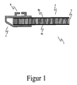
- FIG. 1 shows the transport device 1 according to the invention, which has a frame profile 2 and arranged in the frame profile 2 bottom plate 3.
- the bottom plate 3 comprises a core layer 5 bounded by an upper cover layer 4a and a lower cover layer 4b.
- the upper and lower cover view 4a, 4b is advantageously made of aluminum, while the core layer 5 consists of an aluminum foam, which has a significantly lower mass density and thus contributes significantly to the weight reduction.
- the frame profile can be easily bent outwards to push the bottom plate 3 in the frame section 2. Due to the restoring forces of the frame profile 2, the bottom plate 3 is then held in the frame profile 2 non-positively or positively. Further connecting elements are not required in this embodiment then no more, but are quite possible to support.
- the frame profile thus defines in the region of the receptacle in which the bottom plate 3 is received, a corresponding groove profile, in which the bottom plate 3 can be accommodated.
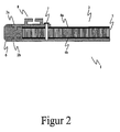
- FIG. 2 also shows a transport device 1 according to the invention, in which the frame profile 2, as in FIG. 1 shown, consists of a separate upper profile wall 2a and a lower profile wall 2b.
- the frame profile 2 and the upper profile wall 2a and the lower profile wall 2b designed such that a shock-absorbing profile 6 is held positively on a circumference of the transport device 1, so that mechanical forces acting on the transport device 1, can be intercepted.
- a fastening means 7 for example a screw or a rivet
- the upper profile wall 2a and the lower profile wall 2b are compressed, so that the bottom plate 3, which is arranged between the upper and the lower profile wall, is pressed with these.
- the bottom plate 3 is thus positively or positively held between the two profile walls 2a and 2b.
- FIG. 1 shows a frame profile 2, on the upper side of a T-slot anchoring profile 8 (so-called seat tracks) is arranged, which can be used for attachment of possible side walls, anchors or the like.
- the lower profile wall 2b formed continuously, so that the entire lower portion of the bottom plate 3 is covered by the profile wall 2b to protect the bottom plate 3 from any damage and occurrence of signs of wear.
Abstract
Description
- Die Erfindung betrifft eine Transportvorrichtung zum Transportieren von Gütern mit einer Grundstruktur, die zumindest ein Rahmenprofil und eine in dem Rahmenprofil angeordnete Bodenplatte umfasst. Die Erfindung betrifft auch eine Verwendung einer solchen erfindungsgemäßen Platte hierfür.
- Durch den Wegfall von Handelsbeschränkungen und einer immer größer werdenden weltweiten Vernetzung der Handelsbeziehungen sowie aufgrund der Zunahme des individualisierten Warentransportes ist seit Jahren eine starke Zunahme im Bereich des Waren- und Güterverkehrs zu beobachten. Damit einhergehend wachsen nicht nur die logistischen Aufgaben. Mit Blick auf unsere Umwelt und die Verknappung unserer Ressourcen stehen heutige Transportunternehmen in der Verpflichtung, den Güterverkehr nicht nur effizient und kostensparend zu bewerkstelligen, sondern eben auch auf die Nachhaltigkeit unserer Ressourcen zu achten.
- So bedeuten Gewichtseinsparungen beim Transport durch Verkehrsmittel jeglicher Art immer auch eine Einsparung von Kraftstoff und somit eine Vergrößerung der Reichweite sowie einen umweltschonenderen Transport, da in der Regel weniger CO2 ausgestoßen wird. Insbesondere Frachtcontainer bzw. Frachtpaletten, die aus einem Rahmen und einer massiven Bodenplatte, meist aus Aluminium, bestehen, sind nicht nur schwer, sondern weisen auch keinerlei Pufferung auf, um mechanische Belastungen, wie sie beispielsweise von einem Gabelstapler verursacht werden, ohne Schäden aufzunehmen. Speziell in der Luftfahrt gibt es Beschränkungen hinsichtlich der maximalen Abfluggewichte. Eine Reduzierung des Gewichtes der Transportvorrichtung bedeutet immer auch eine Erhöhung der mitzunehmenden Nutzlast.
- Darüber hinaus besteht ein Hauptproblem heutzutage darin, dass die Boden- bzw. Frachtpaletten sich während des Gebrauches durchbiegen und somit unter Umständen nicht mehr in dem Verkehrsmittel, beispielsweise einem Flugzeug, befestigt werden können. Viele Unternehmen sind im Luftfrachtverkehr daher dazu gezwungen, solche Luftfrachtpaletten bzw. Luftfrachtcontainer in einer größeren Anzahl als tatsächlich benötigt vorzuhalten, um die beschädigten Paletten oder Container austauschen zu können.
- Es ist daher Aufgabe der vorliegenden Erfindung eine verbesserte Transportvorrichtung anzugeben, welche die aus dem Stand der Technik genannten Nachteile vermeidet bzw. verringert.
- Die Aufgabe wird mit einer Transportvorrichtung der eingangs genannten Art erfindungsgemäß dadurch gelöst, dass die Bodenplatte mindestens eine obere Deckschicht und mindestens eine untere Deckschicht und eine zwischen den Deckschichten angeordnete Kernschicht aufweist.
- Es wird somit vorgeschlagen, dass die Transportvorrichtung, die beispielsweise eine Transportpalette oder aber auch ein Transportcontainer sein kann, ein Rahmenprofil und eine daran angeordnete Bodenplatte aufweist, die aus einer oberen und einer unteren Deckschicht besteht, zwischen denen eine Kernschicht eingebettet ist. Vorteilhafterweise sind die Deckschichten mit der Kernschicht verklebt. Mit einer solchen zusammengesetzten Aufbauweise der Bodenplatte erhöht sich zwar die Aufbauhöhe, die jedoch aufgrund der Gewichtseinsparung bei erhöhter Festigkeit in Kauf genommen wird. Dabei wurde erkannt, dass die verursachte Reduzierung des Frachtvolumens derart gering ist, dass sie nicht weiter ins Gewicht fällt.
- Bevorzugterweise ist die Dichte des Kernmaterials geringer als die Dichte des Materials der Deckschichten, so dass aufgrund der geringeren Dichte der Kernschicht das Gewicht der Bodenplatte und somit der gesamten Transportvorrichtung drastisch reduziert werden kann. Der Kern hat trotz seiner geringen Dichte eine hohe Druckstabilität. Als Materialien für die Deckschichten kommen beispielsweise dünne Aluminiumplatten von ca. 1 mm Dicke in Frage, während die Kernschicht aus einem Aluminiumschaum besteht, der ca. 10-15% der Dichte der Aluminiumdeckschichten hat. Somit lässt sich bei erhöhter Steifigkeit - insbesondere Biegesteifigkeit - das Gewicht reduzieren.
- Für die Deckschichten sind aber auch andere feste Materialien denkbar, wie beispielsweise Faserverbundwerkstoffe. Neben den klassischen Fasern aus Kohlenstoff, Glas oder Aramid und Matrizen aus duroplastischen und thermoplastischen Harzen sind außerdem Bioverbunde denkbar. Sie haben den Vorteil, dass sie recycelbar sind. Die Kernschicht kann aus Schaum, Waben mit oder ohne Füllung, Faltwaben oder sonstiges gefaltetes Material, Balsaholz oder ähnliches bestehen, Die Füllungen der Waben können verschiedene Aufgaben haben. Es können verschiedene Eigenschaften des Kerns verbessert werden, Beispiele hierfür sind Brandschutz und Feuchtigkeitsaufnahme.
- Da Luftfrachtpaletten bzw. Luftfrachtcontainer über spezielle Transportförderbänder bzw. Rollmatten geschoben werden, ist es besonders vorteilhaft, wenn an der Unterseite der Bodenplatte eine abriebfeste Schutzbeschichtung angebracht wird, um die untere Deckschicht der Bodenplatte nicht zu beschädigen und somit die Komposition zu gefährden. Eine solche abriebfeste Schutzbeschichtung kann beispielsweise aus Aluminium oder einem Gummimaterial sein. Eine weitere Ausführung der Verschleißschicht besteht abwechselnd aus zwei Schaum- und zwei Aramidschichten. Die unterste Schicht ist dabei die Aramidschicht, so dass die auftretenden Druckkräfte besser verteilt werden.
- Erfindungsgemäß ist die Bodenplatte in dem Rahmenprofil angeordnet. In einer speziellen Ausführungsform weist das Rahmenprofil ein entsprechendes Nutprofil auf, in das die Bodenplatte derart aufnehmbar ist, dass sie vom Rahmenprofil gehalten wird. Hierfür ist es beispielsweise denkbar, dass das Rahmenprofil vorgespannt ist und beim Zusammensetzen elastisch aufgebogen wird, um die Bodenplatte in das Rahmenprofil einzuschieben. Anschließend wird die Bodenplatte kraftschlüssig in dem Nutprofil gehalten. Dies hat den entscheidenden Vorteil, dass keine weiteren Verbindungselemente notwendig sind, um die Bodenplatte mit dem Rahmenprofil zu verbinden. Andererseits kann bei Beschädigungen die Bodenplatte leicht ausgewechselt werden, was auch an entfernten Orten durch das dortige Personal durchgeführt werden kann.
- Ganz besonders vorteilhaft ist es, wenn das Rahmenprofil eine separate obere und eine untere Profilwand aufweist, zwischen denen die Bodenplatte angeordnet wird und die mit Hilfe von Befestigungsverbindungen bzw. Befestigungsmitteln, wie beispielsweise Schrauben oder Nieten miteinander verbunden werden, so dass die Bodenplatte zwischen den Profilwänden kraft- oder formschlüssig gehalten wird. Dies hat den Vorteil, dass das Rahmenprofil, welches die oberen und unteren Profilwände ausbildet, nicht integral (einstückig) aufgebaut sein muss, was die Montage der Palette bzw. des Frachtcontainers erleichtert.
- Um auch hier die Bodenplatte vor Beschädigung zu schützen, ist es ganz besonders vorteilhaft, wenn die untere Profilwand durchgängig derart ausgebildet ist, dass die gesamte Bodenplatte abgedeckt wird.
- Bevorzugterweise ist an einem Umfang des Rahmenprofils zumindest teilweise ein Stoßdämpfungsprofil angeordnet, um so genannte Impact-Schäden, wie sie beim Transport oder beim Be- und Entladen entstehen können, an den Paletten bzw. an dem Container zu vermeiden. Dazu wird ein beispielsweise elastomeres Profil an dem Rahmen angeordnet, der einen Großteil der kinetischen Energie bei solchen Impacts aufnehmen kann,
- Vorteilhafterweise ist die Bodenplatte im Normalzustand nach oben gewölbt. Wird die Palette bzw, der Container nun mit Stückgut belastet, so wird die Bodenplatte eben und fügt sich somit in den entsprechenden Laderaum ein. Mit der entsprechenden Vorwölbung entgegen der Belastungsrichtung können die Schäden an den Paletten bzw. Containern minimiert werden, die aufgrund der Materialverformung und Überbeanspruchung regelmäßig entstehen.
- Darüber hinaus wird die vorliegende Aufgabe auch mit der Verwendung der oben genannten Bodenplatte für eine Transportvorrichtung mit einem Rahmenprofil, in das die Bodenplatte aufnehmbar ist, gelöst.
- Vorteilhafte Ausgestaltungen zu dieser Verwendung finden sich in den entsprechenden Unteransprüchen.
- Die Erfindung wird anhand der beigefügten Zeichnungen beispielhaft näher erläutert. Es zeigen:
- Figur 1 -
- Transportvorrichtung mit einstückigem Rahmenprofil und
- Figur 2 -
- Rahmenprofil mit Stoßdämpfungsprofil.
-
Figur 1 zeigt die erfindungsgemäße Transportvorrichtung 1, die ein Rahmenprofil 2 und eine in dem Rahmenprofil 2 angeordnete Bodenplatte 3 aufweist. Die Bodenplatte 3 umfasst eine Kernschicht 5, die von einer oberen Deckschicht 4a und einer unteren Deckschicht 4b begrenzt wird. Die obere und die untere Decksicht 4a, 4b ist dabei vorteilhafterweise aus Aluminium gefertigt, während die Kernschicht 5 aus einem Aluminiumschaum besteht, der eine erheblich geringere Massedichte aufweist und somit zur Gewichtsreduktion erheblich beiträgt. - Das Rahmenprofil kann dabei leicht nach außen aufgebogen werden, um die Bodenplatte 3 in dem Rahmenprofil 2 einzuschieben. Aufgrund der Rückstellkräfte des Rahmenprofils 2 wird die Bodenplatte 3 dann in dem Rahmenprofil 2 kraftschlüssig bzw, formschlüssig gehalten. Weitere Verbindungselemente bedarf es in diesem Ausführungsbeispiel dann nicht mehr, sind jedoch zur Unterstützung durchaus denkbar.
- Das Rahmenprofil definiert somit im Bereich der Aufnahme, in dem die Bodenplatte 3 aufgenommen wird, ein entsprechendes Nutprofil, in die die Bodenplatte 3 aufgenommen werden kann.
-
Figur 2 zeigt ebenfalls eine erfindungsgemäße Transportvorrichtung 1, bei der das Rahmenprofil 2, wie inFigur 1 gezeigt, aus einer separaten oberen Profilwand 2a und einer unteren Profilwand 2b besteht. Darüber hinaus ist das Rahmenprofil 2 bzw. die obere Profilwand 2a bzw. die untere Profilwand 2b derart ausgebildet, dass ein Stoßdämpfungsprofil 6 formschlüssig an einem Umfang der Transportvorrichtung 1 gehalten wird, so dass mechanische Kräfte, die auf die Transportvorrichtung 1 wirken, abgefangen werden können. Mit Hilfe eines Befestigungsmittels 7, beispielsweise eine Schraube oder eine Niete, wird die obere Profilwand 2a und die untere Profilwand 2b zusammengedrückt, so dass die Bodenplatte 3, die zwischen der oberen und der unteren Profilwand angeordnet ist, mit diesen verpresst wird. Die Bodenplatte 3 wird somit zwischen den beiden Profilwänden 2a und 2b kraftschlüssig bzw, formschlüssig gehalten. - Sowohl
Figur 1 als auchFigur 2 zeigt ein Rahmenprofil 2, an dessen oberer Seite ein T-Nuten-Verankerungsprofil 8 (so genannte Seat Tracks) angeordnet ist, das zur Befestigung von möglichen Seitenwänden, Verankerungen oder ähnlichem eingesetzt werden kann. Darüber hinaus ist inFigur 2 die untere Profilwand 2b durchgängig ausgebildet, so dass der gesamte untere Bereich der Bodenplatte 3 von der Profilwand 2b abgedeckt wird, um die Bodenplatte 3 vor eventuellen Beschädigungen und Auftreten von Verschleißerscheinungen zu schützen.
Claims (15)
- Transportvorrichtung (1) zum Transportieren von Gütern mit einer Grundstruktur, die zumindest ein Rahmenprofil (2) und eine in dem Rahmenprofil (2) angeordnete Bodenplatte (3) umfasst, wobei die Bodenplatte (3) mindestens eine obere Deckschicht (4a) und mindestens eine untere Deckschicht (4b) und eine zwischen den Deckschichten (4a, 4b) angeordnete Kernschicht (5) aufweist, dadurch gekennzeichnet, dass das Rahmenprofil (2) eine separate obere Profilwand (2a) und eine untere Profilwand (2b) aufweist, zwischen denen die Bodenplatte (3) angeordnet ist und die durch Befestigungsmittel (7) derart verbunden sind, dass die Bodenplatte (3) zwischen den Profilwänden (2a, 2b) gehalten wird.
- Transportvorrichtung (1) zum Transportieren von Gütern mit einer Grundstruktur, die zumindest ein Rahmenprofil (2) und eine in dem Rahmenprofil (2) angeordnete Bodenplatte (3) umfasst, dadurch gekennzeichnet, dass die Bodenplatte (3) mindestens eine obere Deckschicht (4a) und mindestens eine untere Deckschicht (4b) und eine zwischen den Deckschichten (4a, 4b) angeordnete Kernschicht (5) aufweist.
- Transportvorrichtung (1) nach Anspruch 1 oder 2, dadurch gekennzeichnet, dass die Transportvorrichtung (1) ein Frachtcontainer, insbesondere ein Luftfrachtcontainer oder eine Luftfrachtpalette, ist.
- Transportvorrichtung (1) nach einem der vorhergehenden Ansprüche, dadurch gekennzeichnet, dass die Dichte des Kernmaterials geringer ist als die Dichte des Materials der Deckschichten (4a, 4b).
- Transportvorrichtung (1) nach einem der vorhergehenden Ansprüche, dadurch gekennzeichnet, dass an zumindest einer der Deckschichten (4a, 4b) an einer Außenseite eine abriebfeste Schutzbeschichtung, insbesondere aus Aluminium, angeordnet ist.
- Transportvorrichtung (1) nach Anspruch 5, dadurch gekennzeichnet, dass die abriebfeste Schutzbeschichtung aus mindestens einer Schaumschicht und mindestens einer Aramidschicht besteht.
- Transportvorrichtung (1) nach einem der vorhergehenden Ansprüche, dadurch gekennzeichnet, dass das Rahmenprofil (2) ein Nutprofil hat, in das die Bodenplatte (3) derart aufnehmbar ist, dass die Bodenplatte (3) von dem Rahmenprofil (2), insbesondere lösbar, gehalten wird.
- Transportvorrichtung nach einem der vorhergehenden Ansprüche, dadurch gekennzeichnet, dass das Rahmenprofil (2) eine obere Profilwand (2a) und eine untere Profilwand (2b) aufweist, zwischen denen die Bodenplatte (3) angeordnet ist und die durch Befestigungsmittel (7) derart verbunden sind, dass die Bodenplatte (3) zwischen den Profilwänden (2a, 2b) gehalten wird.
- Transportvorrichtung (1) nach Anspruch 8, dadurch gekennzeichnet, dass die untere Profilwand (2b) durchgängig ausgebildet ist.
- Transportvorrichtung (1) nach einem der vorhergehenden Ansprüche, dadurch gekennzeichnet, dass an einem Umfang des Rahmenprofils (2) zumindest teilweise ein Stoßdämpfungsprofil (6) angeordnet ist.
- Transportvorrichtung nach einem der vorhergehenden Ansprüche, dadurch gekennzeichnet, dass die Bodenplatte (3) entgegen der Belastungsrichtung im unbelasteten Zustand gewölbt ist.
- Transportvorrichtung nach einem der vorhergehenden Ansprüche, dadurch gekennzeichnet, dass die Deckschichten mit der Kernschicht verklebt sind.
- Verwendung einer Bodenplatte (3) nach einem der vorhergehenden Ansprüche- mit mindestens einer oberen Deckschicht (4a) und mindestens einer unteren Deckschicht (4b) und einer zwischen den Deckschichten (4a, 4b) angeordneten Kernschicht (5)- für eine Transportvorrichtung (1) mit einem Rahmenprofil (2), in das die Bodenplatte (3) aufnehmbar ist.
- Verwendung nach Anspruch 13, dadurch gekennzeichnet, dass die Dichte des Kernmaterials geringer ist als die Dichte des Materials der Decksichten.
- Verwendung nach Anspruch 13 oder 14, dadurch gekennzeichnet, dass die Deckschichten mit der Kernschicht verklebt sind.
Ai/sb
Applications Claiming Priority (1)
| Application Number | Priority Date | Filing Date | Title |
|---|---|---|---|
| DE201010045808 DE102010045808A1 (de) | 2010-09-20 | 2010-09-20 | Transportvorrichtung |
Publications (2)
| Publication Number | Publication Date |
|---|---|
| EP2431302A1 true EP2431302A1 (de) | 2012-03-21 |
| EP2431302B1 EP2431302B1 (de) | 2016-08-17 |
Family
ID=44650897
Family Applications (1)
| Application Number | Title | Priority Date | Filing Date |
|---|---|---|---|
| EP11007644.5A Not-in-force EP2431302B1 (de) | 2010-09-20 | 2011-09-20 | Transportvorrichtung |
Country Status (2)
| Country | Link |
|---|---|
| EP (1) | EP2431302B1 (de) |
| DE (1) | DE102010045808A1 (de) |
Cited By (1)
| Publication number | Priority date | Publication date | Assignee | Title |
|---|---|---|---|---|
| NL2010999C2 (en) * | 2013-06-18 | 2014-12-22 | Driessen Air Cargo Equipment B V | Airfreight pallet, method for manufacturing an airfreight pallet. |
Families Citing this family (4)
| Publication number | Priority date | Publication date | Assignee | Title |
|---|---|---|---|---|
| DE102010049776B4 (de) | 2010-10-29 | 2015-09-24 | Deutsches Zentrum für Luft- und Raumfahrt e.V. | Bodenplatte |
| DE202012012860U1 (de) | 2012-09-10 | 2014-02-06 | Deutsches Zentrum für Luft- und Raumfahrt e.V. | Luftfrachtcontainer |
| DE102014107357A1 (de) * | 2014-03-12 | 2015-09-17 | Telair International Gmbh | Bodenplatte und Bodenelement für eine Frachtpalette und/oder einen Frachtcontainer sowie Verfahren zur Herstellung einer entsprechenden Bodenplatte und eines entsprechenden Bodenelements |
| DE102016112310A1 (de) | 2016-07-05 | 2017-08-17 | Ostfalia Hochschule Für Angewandte Wissenschaften - Hochschule Braunschweig/Wolfenbüttel | Ladeboden für ein Fahrzeug und Fahrzeug mit dem Ladeboden |
Citations (4)
| Publication number | Priority date | Publication date | Assignee | Title |
|---|---|---|---|---|
| US3405835A (en) * | 1964-02-11 | 1968-10-15 | Charles M. Eby | Aluminum knock-down collapsible container |
| WO1993020300A1 (en) * | 1992-03-30 | 1993-10-14 | Ljubomir Gnjatovic | Reinforced wall structure |
| DE4331835A1 (de) * | 1993-09-20 | 1995-03-30 | Deutsche Aerospace | Luftfrachtcontainer |
| US20030230589A1 (en) * | 2002-05-27 | 2003-12-18 | Ming-Jong Wang | Connection device for use with a blast-resistant container |
Family Cites Families (4)
| Publication number | Priority date | Publication date | Assignee | Title |
|---|---|---|---|---|
| US3552329A (en) * | 1969-12-10 | 1971-01-05 | Tridair Industries | Panel construction and method |
| DE102006006511A1 (de) * | 2006-02-10 | 2007-08-16 | Acep - Advanced Composites Engineering + Production Gmbh | Frachtträger, insbesondere Luftfrachtträger |
| DE102007035228B4 (de) * | 2007-05-15 | 2010-12-09 | Rcs Reinforced Composite Solutions Gmbh | Transportbehälter |
| DE202009000784U1 (de) * | 2009-01-20 | 2010-06-17 | Wecon Gmbh Nutzfahrzeuge-Container-Technik | Fahrzeug-Ladeboden mit vorgebogener Bodenplatte |
-
2010
- 2010-09-20 DE DE201010045808 patent/DE102010045808A1/de not_active Withdrawn
-
2011
- 2011-09-20 EP EP11007644.5A patent/EP2431302B1/de not_active Not-in-force
Patent Citations (4)
| Publication number | Priority date | Publication date | Assignee | Title |
|---|---|---|---|---|
| US3405835A (en) * | 1964-02-11 | 1968-10-15 | Charles M. Eby | Aluminum knock-down collapsible container |
| WO1993020300A1 (en) * | 1992-03-30 | 1993-10-14 | Ljubomir Gnjatovic | Reinforced wall structure |
| DE4331835A1 (de) * | 1993-09-20 | 1995-03-30 | Deutsche Aerospace | Luftfrachtcontainer |
| US20030230589A1 (en) * | 2002-05-27 | 2003-12-18 | Ming-Jong Wang | Connection device for use with a blast-resistant container |
Cited By (1)
| Publication number | Priority date | Publication date | Assignee | Title |
|---|---|---|---|---|
| NL2010999C2 (en) * | 2013-06-18 | 2014-12-22 | Driessen Air Cargo Equipment B V | Airfreight pallet, method for manufacturing an airfreight pallet. |
Also Published As
| Publication number | Publication date |
|---|---|
| DE102010045808A1 (de) | 2012-03-22 |
| EP2431302B1 (de) | 2016-08-17 |
Similar Documents
| Publication | Publication Date | Title |
|---|---|---|
| EP2431302B1 (de) | Transportvorrichtung | |
| EP1799603B1 (de) | Modulare aufzugskabine | |
| DE102006049482B4 (de) | Container-Bodenplatte, insbesondere für einen Kühlcontainer | |
| DE102014107357A1 (de) | Bodenplatte und Bodenelement für eine Frachtpalette und/oder einen Frachtcontainer sowie Verfahren zur Herstellung einer entsprechenden Bodenplatte und eines entsprechenden Bodenelements | |
| DE102011122589A1 (de) | Bauelement zur Wärmedämmung | |
| EP2723656A1 (de) | Frachtaufnahmeeinrichtung insbesondere für das beladen von flugzeugen, verfahren zur herstellung einer frachtaufnahmeeinrichtung sowie verwendung eines pultrudierten faserverstärkten profilelements für eine frachtaufnahmeeinrichtung | |
| EP2116447B1 (de) | Querträger für ein Bodenelement eines Fahrzeugs, wie eines Lastkraftwagens, Aufliegers oder Anhängers, und Bodenelement mit einem solchen Querträger | |
| DE102011050893B4 (de) | Frachtcontainer und Verfahren zur Herstellung eines Frachtcontainers | |
| DE102012106321A1 (de) | Holzturm für Windkraftanlage | |
| EP2722285B1 (de) | Kunststoffpalette mit Versteifungselement | |
| DE102010049776B4 (de) | Bodenplatte | |
| DE102013106919A1 (de) | Holz-Beton-Verbundkonstruktion | |
| DE202008002302U1 (de) | Transportkarren für die Flugzeugbeladung mit Standardbehältern | |
| DE102016201484A1 (de) | Beschusshemmendes Bauteil zum Bau eines Schutzraumes | |
| DE102014218450A1 (de) | Fahrzeugkopf zur Befestigung an der Stirnseite eines spurgebundenen Fahrzeuges, insbesondere eines Schienenfahrzeuges | |
| EP0814013A1 (de) | Wagenkastenboden für ein Lastkraftfahrzeug oder für einen Lastkraftfahrzeuganhänger | |
| DE202006012140U1 (de) | Modularer, begehbarer Belag für Gerüste | |
| CH683091A5 (de) | Schwerlastboden, insbesondere für Lagerbehälter. | |
| DE102005031653A1 (de) | Füllung für Boden- und Seitenwandsysteme auf Stück- und Massengutaufbauten für Land- und Wasserfahrzeuge | |
| EP1234776A2 (de) | Palette zum Transport von Plattenstapeln | |
| WO2002066758A1 (de) | Vorgefertigtes bauelement für gebäude | |
| DE2624915C2 (de) | ||
| DE202012012860U1 (de) | Luftfrachtcontainer | |
| DE2130899A1 (de) | Palette | |
| DE60126095T2 (de) | Auswechselbehälter und eingebetteter träger dafür |
Legal Events
| Date | Code | Title | Description |
|---|---|---|---|
| PUAI | Public reference made under article 153(3) epc to a published international application that has entered the european phase |
Free format text: ORIGINAL CODE: 0009012 |
|
| AK | Designated contracting states |
Kind code of ref document: A1 Designated state(s): AL AT BE BG CH CY CZ DE DK EE ES FI FR GB GR HR HU IE IS IT LI LT LU LV MC MK MT NL NO PL PT RO RS SE SI SK SM TR |
|
| AX | Request for extension of the european patent |
Extension state: BA ME |
|
| RAP1 | Party data changed (applicant data changed or rights of an application transferred) |
Owner name: DEUTSCHES ZENTRUM FUER LUFT- UND RAUMFAHRT E.V. |
|
| 17P | Request for examination filed |
Effective date: 20120921 |
|
| 17Q | First examination report despatched |
Effective date: 20140305 |
|
| REG | Reference to a national code |
Ref country code: DE Ref legal event code: R079 Ref document number: 502011010404 Country of ref document: DE Free format text: PREVIOUS MAIN CLASS: B65D0088140000 Ipc: B65D0090000000 |
|
| GRAP | Despatch of communication of intention to grant a patent |
Free format text: ORIGINAL CODE: EPIDOSNIGR1 |
|
| RIC1 | Information provided on ipc code assigned before grant |
Ipc: B65D 90/02 20060101ALI20160204BHEP Ipc: B65D 88/14 20060101ALI20160204BHEP Ipc: B65D 90/00 20060101AFI20160204BHEP |
|
| INTG | Intention to grant announced |
Effective date: 20160225 |
|
| GRAS | Grant fee paid |
Free format text: ORIGINAL CODE: EPIDOSNIGR3 |
|
| GRAA | (expected) grant |
Free format text: ORIGINAL CODE: 0009210 |
|
| AK | Designated contracting states |
Kind code of ref document: B1 Designated state(s): AL AT BE BG CH CY CZ DE DK EE ES FI FR GB GR HR HU IE IS IT LI LT LU LV MC MK MT NL NO PL PT RO RS SE SI SK SM TR |
|
| REG | Reference to a national code |
Ref country code: GB Ref legal event code: FG4D Free format text: NOT ENGLISH |
|
| REG | Reference to a national code |
Ref country code: CH Ref legal event code: EP |
|
| REG | Reference to a national code |
Ref country code: IE Ref legal event code: FG4D Free format text: LANGUAGE OF EP DOCUMENT: GERMAN |
|
| REG | Reference to a national code |
Ref country code: AT Ref legal event code: REF Ref document number: 820823 Country of ref document: AT Kind code of ref document: T Effective date: 20160915 |
|
| REG | Reference to a national code |
Ref country code: DE Ref legal event code: R096 Ref document number: 502011010404 Country of ref document: DE Ref country code: FR Ref legal event code: PLFP Year of fee payment: 6 |
|
| REG | Reference to a national code |
Ref country code: NL Ref legal event code: MP Effective date: 20160817 |
|
| REG | Reference to a national code |
Ref country code: LT Ref legal event code: MG4D |
|
| PG25 | Lapsed in a contracting state [announced via postgrant information from national office to epo] |
Ref country code: RS Free format text: LAPSE BECAUSE OF FAILURE TO SUBMIT A TRANSLATION OF THE DESCRIPTION OR TO PAY THE FEE WITHIN THE PRESCRIBED TIME-LIMIT Effective date: 20160817 Ref country code: HR Free format text: LAPSE BECAUSE OF FAILURE TO SUBMIT A TRANSLATION OF THE DESCRIPTION OR TO PAY THE FEE WITHIN THE PRESCRIBED TIME-LIMIT Effective date: 20160817 Ref country code: IT Free format text: LAPSE BECAUSE OF FAILURE TO SUBMIT A TRANSLATION OF THE DESCRIPTION OR TO PAY THE FEE WITHIN THE PRESCRIBED TIME-LIMIT Effective date: 20160817 Ref country code: NO Free format text: LAPSE BECAUSE OF FAILURE TO SUBMIT A TRANSLATION OF THE DESCRIPTION OR TO PAY THE FEE WITHIN THE PRESCRIBED TIME-LIMIT Effective date: 20161117 Ref country code: FI Free format text: LAPSE BECAUSE OF FAILURE TO SUBMIT A TRANSLATION OF THE DESCRIPTION OR TO PAY THE FEE WITHIN THE PRESCRIBED TIME-LIMIT Effective date: 20160817 Ref country code: LT Free format text: LAPSE BECAUSE OF FAILURE TO SUBMIT A TRANSLATION OF THE DESCRIPTION OR TO PAY THE FEE WITHIN THE PRESCRIBED TIME-LIMIT Effective date: 20160817 Ref country code: NL Free format text: LAPSE BECAUSE OF FAILURE TO SUBMIT A TRANSLATION OF THE DESCRIPTION OR TO PAY THE FEE WITHIN THE PRESCRIBED TIME-LIMIT Effective date: 20160817 |
|
| PG25 | Lapsed in a contracting state [announced via postgrant information from national office to epo] |
Ref country code: SE Free format text: LAPSE BECAUSE OF FAILURE TO SUBMIT A TRANSLATION OF THE DESCRIPTION OR TO PAY THE FEE WITHIN THE PRESCRIBED TIME-LIMIT Effective date: 20160817 Ref country code: BE Free format text: LAPSE BECAUSE OF NON-PAYMENT OF DUE FEES Effective date: 20160930 Ref country code: PL Free format text: LAPSE BECAUSE OF FAILURE TO SUBMIT A TRANSLATION OF THE DESCRIPTION OR TO PAY THE FEE WITHIN THE PRESCRIBED TIME-LIMIT Effective date: 20160817 Ref country code: ES Free format text: LAPSE BECAUSE OF FAILURE TO SUBMIT A TRANSLATION OF THE DESCRIPTION OR TO PAY THE FEE WITHIN THE PRESCRIBED TIME-LIMIT Effective date: 20160817 Ref country code: LV Free format text: LAPSE BECAUSE OF FAILURE TO SUBMIT A TRANSLATION OF THE DESCRIPTION OR TO PAY THE FEE WITHIN THE PRESCRIBED TIME-LIMIT Effective date: 20160817 Ref country code: PT Free format text: LAPSE BECAUSE OF FAILURE TO SUBMIT A TRANSLATION OF THE DESCRIPTION OR TO PAY THE FEE WITHIN THE PRESCRIBED TIME-LIMIT Effective date: 20161219 Ref country code: GR Free format text: LAPSE BECAUSE OF FAILURE TO SUBMIT A TRANSLATION OF THE DESCRIPTION OR TO PAY THE FEE WITHIN THE PRESCRIBED TIME-LIMIT Effective date: 20161118 |
|
| PG25 | Lapsed in a contracting state [announced via postgrant information from national office to epo] |
Ref country code: EE Free format text: LAPSE BECAUSE OF FAILURE TO SUBMIT A TRANSLATION OF THE DESCRIPTION OR TO PAY THE FEE WITHIN THE PRESCRIBED TIME-LIMIT Effective date: 20160817 Ref country code: RO Free format text: LAPSE BECAUSE OF FAILURE TO SUBMIT A TRANSLATION OF THE DESCRIPTION OR TO PAY THE FEE WITHIN THE PRESCRIBED TIME-LIMIT Effective date: 20160817 |
|
| REG | Reference to a national code |
Ref country code: CH Ref legal event code: PL |
|
| REG | Reference to a national code |
Ref country code: DE Ref legal event code: R097 Ref document number: 502011010404 Country of ref document: DE |
|
| PG25 | Lapsed in a contracting state [announced via postgrant information from national office to epo] |
Ref country code: DK Free format text: LAPSE BECAUSE OF FAILURE TO SUBMIT A TRANSLATION OF THE DESCRIPTION OR TO PAY THE FEE WITHIN THE PRESCRIBED TIME-LIMIT Effective date: 20160817 Ref country code: SM Free format text: LAPSE BECAUSE OF FAILURE TO SUBMIT A TRANSLATION OF THE DESCRIPTION OR TO PAY THE FEE WITHIN THE PRESCRIBED TIME-LIMIT Effective date: 20160817 Ref country code: CZ Free format text: LAPSE BECAUSE OF FAILURE TO SUBMIT A TRANSLATION OF THE DESCRIPTION OR TO PAY THE FEE WITHIN THE PRESCRIBED TIME-LIMIT Effective date: 20160817 Ref country code: BG Free format text: LAPSE BECAUSE OF FAILURE TO SUBMIT A TRANSLATION OF THE DESCRIPTION OR TO PAY THE FEE WITHIN THE PRESCRIBED TIME-LIMIT Effective date: 20161117 Ref country code: SK Free format text: LAPSE BECAUSE OF FAILURE TO SUBMIT A TRANSLATION OF THE DESCRIPTION OR TO PAY THE FEE WITHIN THE PRESCRIBED TIME-LIMIT Effective date: 20160817 |
|
| PLBE | No opposition filed within time limit |
Free format text: ORIGINAL CODE: 0009261 |
|
| STAA | Information on the status of an ep patent application or granted ep patent |
Free format text: STATUS: NO OPPOSITION FILED WITHIN TIME LIMIT |
|
| REG | Reference to a national code |
Ref country code: IE Ref legal event code: MM4A |
|
| PG25 | Lapsed in a contracting state [announced via postgrant information from national office to epo] |
Ref country code: MC Free format text: LAPSE BECAUSE OF FAILURE TO SUBMIT A TRANSLATION OF THE DESCRIPTION OR TO PAY THE FEE WITHIN THE PRESCRIBED TIME-LIMIT Effective date: 20160817 |
|
| 26N | No opposition filed |
Effective date: 20170518 |
|
| GBPC | Gb: european patent ceased through non-payment of renewal fee |
Effective date: 20161117 |
|
| PG25 | Lapsed in a contracting state [announced via postgrant information from national office to epo] |
Ref country code: LI Free format text: LAPSE BECAUSE OF NON-PAYMENT OF DUE FEES Effective date: 20160930 Ref country code: IE Free format text: LAPSE BECAUSE OF NON-PAYMENT OF DUE FEES Effective date: 20160920 Ref country code: CH Free format text: LAPSE BECAUSE OF NON-PAYMENT OF DUE FEES Effective date: 20160930 |
|
| REG | Reference to a national code |
Ref country code: FR Ref legal event code: PLFP Year of fee payment: 7 |
|
| PG25 | Lapsed in a contracting state [announced via postgrant information from national office to epo] |
Ref country code: LU Free format text: LAPSE BECAUSE OF NON-PAYMENT OF DUE FEES Effective date: 20160920 Ref country code: SI Free format text: LAPSE BECAUSE OF FAILURE TO SUBMIT A TRANSLATION OF THE DESCRIPTION OR TO PAY THE FEE WITHIN THE PRESCRIBED TIME-LIMIT Effective date: 20160817 |
|
| PGFP | Annual fee paid to national office [announced via postgrant information from national office to epo] |
Ref country code: FR Payment date: 20170823 Year of fee payment: 7 |
|
| REG | Reference to a national code |
Ref country code: AT Ref legal event code: MM01 Ref document number: 820823 Country of ref document: AT Kind code of ref document: T Effective date: 20160920 |
|
| REG | Reference to a national code |
Ref country code: BE Ref legal event code: MM Effective date: 20160930 |
|
| PG25 | Lapsed in a contracting state [announced via postgrant information from national office to epo] |
Ref country code: GB Free format text: LAPSE BECAUSE OF NON-PAYMENT OF DUE FEES Effective date: 20161117 |
|
| PG25 | Lapsed in a contracting state [announced via postgrant information from national office to epo] |
Ref country code: AT Free format text: LAPSE BECAUSE OF NON-PAYMENT OF DUE FEES Effective date: 20160920 |
|
| PG25 | Lapsed in a contracting state [announced via postgrant information from national office to epo] |
Ref country code: HU Free format text: LAPSE BECAUSE OF FAILURE TO SUBMIT A TRANSLATION OF THE DESCRIPTION OR TO PAY THE FEE WITHIN THE PRESCRIBED TIME-LIMIT; INVALID AB INITIO Effective date: 20110920 Ref country code: CY Free format text: LAPSE BECAUSE OF FAILURE TO SUBMIT A TRANSLATION OF THE DESCRIPTION OR TO PAY THE FEE WITHIN THE PRESCRIBED TIME-LIMIT Effective date: 20160817 |
|
| PG25 | Lapsed in a contracting state [announced via postgrant information from national office to epo] |
Ref country code: IS Free format text: LAPSE BECAUSE OF FAILURE TO SUBMIT A TRANSLATION OF THE DESCRIPTION OR TO PAY THE FEE WITHIN THE PRESCRIBED TIME-LIMIT Effective date: 20160817 Ref country code: MK Free format text: LAPSE BECAUSE OF FAILURE TO SUBMIT A TRANSLATION OF THE DESCRIPTION OR TO PAY THE FEE WITHIN THE PRESCRIBED TIME-LIMIT Effective date: 20160817 Ref country code: MT Free format text: LAPSE BECAUSE OF FAILURE TO SUBMIT A TRANSLATION OF THE DESCRIPTION OR TO PAY THE FEE WITHIN THE PRESCRIBED TIME-LIMIT Effective date: 20160817 Ref country code: TR Free format text: LAPSE BECAUSE OF FAILURE TO SUBMIT A TRANSLATION OF THE DESCRIPTION OR TO PAY THE FEE WITHIN THE PRESCRIBED TIME-LIMIT Effective date: 20160817 |
|
| PG25 | Lapsed in a contracting state [announced via postgrant information from national office to epo] |
Ref country code: AL Free format text: LAPSE BECAUSE OF FAILURE TO SUBMIT A TRANSLATION OF THE DESCRIPTION OR TO PAY THE FEE WITHIN THE PRESCRIBED TIME-LIMIT Effective date: 20160817 |
|
| PG25 | Lapsed in a contracting state [announced via postgrant information from national office to epo] |
Ref country code: FR Free format text: LAPSE BECAUSE OF NON-PAYMENT OF DUE FEES Effective date: 20180930 |
|
| PGFP | Annual fee paid to national office [announced via postgrant information from national office to epo] |
Ref country code: DE Payment date: 20210812 Year of fee payment: 11 |
|
| REG | Reference to a national code |
Ref country code: DE Ref legal event code: R119 Ref document number: 502011010404 Country of ref document: DE |
|
| PG25 | Lapsed in a contracting state [announced via postgrant information from national office to epo] |
Ref country code: DE Free format text: LAPSE BECAUSE OF NON-PAYMENT OF DUE FEES Effective date: 20230401 |