EP2431237B1 - Side airbag device for vehicle - Google Patents
Side airbag device for vehicle Download PDFInfo
- Publication number
- EP2431237B1 EP2431237B1 EP09844600.8A EP09844600A EP2431237B1 EP 2431237 B1 EP2431237 B1 EP 2431237B1 EP 09844600 A EP09844600 A EP 09844600A EP 2431237 B1 EP2431237 B1 EP 2431237B1
- Authority
- EP
- European Patent Office
- Prior art keywords
- chamber
- seat
- diffuser
- fabric
- pressure
- Prior art date
- Legal status (The legal status is an assumption and is not a legal conclusion. Google has not performed a legal analysis and makes no representation as to the accuracy of the status listed.)
- Not-in-force
Links
- 239000004744 fabric Substances 0.000 claims description 114
- 238000005192 partition Methods 0.000 claims description 49
- 230000033228 biological regulation Effects 0.000 claims description 27
- 230000002787 reinforcement Effects 0.000 claims description 12
- 238000009958 sewing Methods 0.000 claims description 11
- 210000001015 abdomen Anatomy 0.000 claims description 9
- 230000001105 regulatory effect Effects 0.000 claims description 6
- 238000000638 solvent extraction Methods 0.000 claims description 3
- 238000010586 diagram Methods 0.000 description 20
- 230000000694 effects Effects 0.000 description 10
- 230000000452 restraining effect Effects 0.000 description 8
- 238000004519 manufacturing process Methods 0.000 description 3
- 238000009434 installation Methods 0.000 description 2
- 238000009941 weaving Methods 0.000 description 2
- 230000001154 acute effect Effects 0.000 description 1
- 239000011248 coating agent Substances 0.000 description 1
- 238000000576 coating method Methods 0.000 description 1
- 230000007423 decrease Effects 0.000 description 1
- 230000003111 delayed effect Effects 0.000 description 1
- 230000012447 hatching Effects 0.000 description 1
- 230000035807 sensation Effects 0.000 description 1
- 238000003466 welding Methods 0.000 description 1
Images


Classifications
-
- B—PERFORMING OPERATIONS; TRANSPORTING
- B60—VEHICLES IN GENERAL
- B60R—VEHICLES, VEHICLE FITTINGS, OR VEHICLE PARTS, NOT OTHERWISE PROVIDED FOR
- B60R21/00—Arrangements or fittings on vehicles for protecting or preventing injuries to occupants or pedestrians in case of accidents or other traffic risks
- B60R21/02—Occupant safety arrangements or fittings, e.g. crash pads
- B60R21/16—Inflatable occupant restraints or confinements designed to inflate upon impact or impending impact, e.g. air bags
- B60R21/23—Inflatable members
- B60R21/231—Inflatable members characterised by their shape, construction or spatial configuration
- B60R21/23138—Inflatable members characterised by their shape, construction or spatial configuration specially adapted for side protection
-
- B—PERFORMING OPERATIONS; TRANSPORTING
- B60—VEHICLES IN GENERAL
- B60R—VEHICLES, VEHICLE FITTINGS, OR VEHICLE PARTS, NOT OTHERWISE PROVIDED FOR
- B60R21/00—Arrangements or fittings on vehicles for protecting or preventing injuries to occupants or pedestrians in case of accidents or other traffic risks
- B60R21/02—Occupant safety arrangements or fittings, e.g. crash pads
- B60R21/16—Inflatable occupant restraints or confinements designed to inflate upon impact or impending impact, e.g. air bags
- B60R21/23—Inflatable members
- B60R21/231—Inflatable members characterised by their shape, construction or spatial configuration
- B60R21/233—Inflatable members characterised by their shape, construction or spatial configuration comprising a plurality of individual compartments; comprising two or more bag-like members, one within the other
-
- B—PERFORMING OPERATIONS; TRANSPORTING
- B60—VEHICLES IN GENERAL
- B60R—VEHICLES, VEHICLE FITTINGS, OR VEHICLE PARTS, NOT OTHERWISE PROVIDED FOR
- B60R21/00—Arrangements or fittings on vehicles for protecting or preventing injuries to occupants or pedestrians in case of accidents or other traffic risks
- B60R21/02—Occupant safety arrangements or fittings, e.g. crash pads
- B60R21/16—Inflatable occupant restraints or confinements designed to inflate upon impact or impending impact, e.g. air bags
- B60R21/23—Inflatable members
- B60R21/239—Inflatable members characterised by their venting means
-
- B—PERFORMING OPERATIONS; TRANSPORTING
- B60—VEHICLES IN GENERAL
- B60R—VEHICLES, VEHICLE FITTINGS, OR VEHICLE PARTS, NOT OTHERWISE PROVIDED FOR
- B60R21/00—Arrangements or fittings on vehicles for protecting or preventing injuries to occupants or pedestrians in case of accidents or other traffic risks
- B60R21/02—Occupant safety arrangements or fittings, e.g. crash pads
- B60R21/16—Inflatable occupant restraints or confinements designed to inflate upon impact or impending impact, e.g. air bags
- B60R21/26—Inflatable occupant restraints or confinements designed to inflate upon impact or impending impact, e.g. air bags characterised by the inflation fluid source or means to control inflation fluid flow
- B60R21/261—Inflatable occupant restraints or confinements designed to inflate upon impact or impending impact, e.g. air bags characterised by the inflation fluid source or means to control inflation fluid flow with means other than bag structure to diffuse or guide inflation fluid
-
- B—PERFORMING OPERATIONS; TRANSPORTING
- B60—VEHICLES IN GENERAL
- B60R—VEHICLES, VEHICLE FITTINGS, OR VEHICLE PARTS, NOT OTHERWISE PROVIDED FOR
- B60R21/00—Arrangements or fittings on vehicles for protecting or preventing injuries to occupants or pedestrians in case of accidents or other traffic risks
- B60R21/02—Occupant safety arrangements or fittings, e.g. crash pads
- B60R21/16—Inflatable occupant restraints or confinements designed to inflate upon impact or impending impact, e.g. air bags
- B60R21/23—Inflatable members
- B60R21/231—Inflatable members characterised by their shape, construction or spatial configuration
- B60R21/23138—Inflatable members characterised by their shape, construction or spatial configuration specially adapted for side protection
- B60R2021/23146—Inflatable members characterised by their shape, construction or spatial configuration specially adapted for side protection seat mounted
-
- B—PERFORMING OPERATIONS; TRANSPORTING
- B60—VEHICLES IN GENERAL
- B60R—VEHICLES, VEHICLE FITTINGS, OR VEHICLE PARTS, NOT OTHERWISE PROVIDED FOR
- B60R21/00—Arrangements or fittings on vehicles for protecting or preventing injuries to occupants or pedestrians in case of accidents or other traffic risks
- B60R21/02—Occupant safety arrangements or fittings, e.g. crash pads
- B60R21/16—Inflatable occupant restraints or confinements designed to inflate upon impact or impending impact, e.g. air bags
- B60R21/23—Inflatable members
- B60R21/231—Inflatable members characterised by their shape, construction or spatial configuration
- B60R21/233—Inflatable members characterised by their shape, construction or spatial configuration comprising a plurality of individual compartments; comprising two or more bag-like members, one within the other
- B60R2021/23324—Inner walls crating separate compartments, e.g. communicating with vents
-
- B—PERFORMING OPERATIONS; TRANSPORTING
- B60—VEHICLES IN GENERAL
- B60R—VEHICLES, VEHICLE FITTINGS, OR VEHICLE PARTS, NOT OTHERWISE PROVIDED FOR
- B60R21/00—Arrangements or fittings on vehicles for protecting or preventing injuries to occupants or pedestrians in case of accidents or other traffic risks
- B60R21/02—Occupant safety arrangements or fittings, e.g. crash pads
- B60R21/16—Inflatable occupant restraints or confinements designed to inflate upon impact or impending impact, e.g. air bags
- B60R21/20—Arrangements for storing inflatable members in their non-use or deflated condition; Arrangement or mounting of air bag modules or components
- B60R21/217—Inflation fluid source retainers, e.g. reaction canisters; Connection of bags, covers, diffusers or inflation fluid sources therewith or together
- B60R21/2171—Inflation fluid source retainers, e.g. reaction canisters; Connection of bags, covers, diffusers or inflation fluid sources therewith or together specially adapted for elongated cylindrical or bottle-like inflators with a symmetry axis perpendicular to the main direction of bag deployment, e.g. extruded reaction canisters
Definitions
- the present invention relates to a side airbag device for a vehicle.
- Patent Reference 1 A structure has been disclosed (see Patent Reference 1) in which the interior of an airbag for side impacts is partitioned into an upper chamber and a lower chamber by a seam, a communication portion that communicates between the upper chamber and the lower chamber is formed between the seam and a rear edge of the airbag, a tubular check valve is provided at the communication portion, a gas generator is disposed in the check valve, and an outflow of gas from the lower chamber to the upper chamber is impeded by the check valve.
- gas pressure in the lower chamber is maintained at a high pressure.
- Patent Reference 1 Japanese Patent Application Laid-Open (JP-A) No. 2004-256017
- the related art example mentioned above has a structure in which the check valve is inflated in a substantially tubular shape and a high-pressure portion is formed by gas being discharged radially from an end portion of the gas generator, and the gas is supplied to each of the upper chamber and the lower chamber using pressure differences between the high-pressure portion and the upper chamber and lower chamber. Therefore, it is necessary for the check valve to have the tubular shape. Moreover, in order to restrict the passage of gas around the check valve between the upper chamber and the lower chamber, side edges at the airbag front side of the check valve must be sewn to the seam or the like partitioning the upper chamber and lower chamber, and it is difficult to guarantee a bag thickness of the airbag in the region dividing the upper and lower chambers.
- an object of the present invention is, with a simple structure, to promptly inflate and expand a high-pressure chamber of a side airbag and to allow the pressure in the high-pressure chamber to be maintained for a long-time.
- the present invention includes: a side airbag that includes a high-pressure chamber, which has a high pressure at a time of inflation and expansion, and a low-pressure chamber, which has a lower pressure than the high-pressure chamber, the high-pressure chamber and the low-pressure chamber each inflating and expanding at a time of side collision; a partition wall that is disposed in the side airbag and partitions the high-pressure chamber from the low-pressure chamber; an inflator that is disposed in the low-pressure chamber in a state in which a gas discharge section faces the high-pressure chamber and is disposed at the low-pressure chamber side relative to the partition wall, that supplies gas for inflation mainly toward the high-pressure chamber and that also supplies the gas for inflation to the low-pressure chamber; and a check valve that is disposed at the partition wall, that permits the gas discharged from the gas discharge section of the inflator to flow from the low-pressure chamber to the high-pressure chamber, and that restricts a flow of the gas in the opposite direction.
- the side airbag includes the high-pressure chamber that has a high pressure during inflation and expansion and the low-pressure chamber that has a lower pressure than the high-pressure chamber, and the inflator is disposed in the low-pressure chamber with the gas discharge section facing the high-pressure chamber and being disposed at the low-pressure chamber side relative to the partition wall.
- the inflator operates and the gas for inflation that is discharged from the gas discharge section of the inflator is supplied mainly to the high-pressure chamber, and is also supplied to the low-pressure chamber of the side airbag.
- the high-pressure chamber and low-pressure chamber are partitioned by the partition wall.
- the check valve provided at the partition wall is opened by the pressure of the gas supplied from the inflator in the low-pressure chamber toward the high-pressure chamber, and allows the gas to flow from the low-pressure chamber into the high-pressure chamber.
- the gas is supplied with precedence to the high-pressure chamber, and the high-pressure chamber promptly inflates and expands and has a higher pressure than the low-pressure chamber.
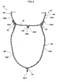
- the inflator completes the discharge of the gas, the gas tries to flow back from the high-pressure chamber to the low-pressure chamber, but the check valve restricts such flow of the gas.
- the inner pressure of the high-pressure chamber may be maintained for a long time.
- An aspect of the present invention is the side airbag device for a vehicle in which, in the side airbag in an inflated and expanded state, the inflator is disposed in the side airbag at a seat rearward side with respect to a vehicle seat, the partition wall is disposed at a position that corresponds with an abdomen area of an occupant sitting on the vehicle seat, the high-pressure chamber is a lower chamber that corresponds with a waist area of the occupant, and the low-pressure chamber is an upper chamber that corresponds with at least one of a chest area or a shoulder area of the occupant.
- the high-pressure chamber is the lower chamber corresponding with the waist area of an occupant
- the low-pressure chamber is the upper chamber corresponding with one or both of the chest area and shoulder area of the occupant.
- the waist area of the occupant sitting on the vehicle seat may be restrained by the lower chamber promptly and at a high pressure
- one or both of the chest area and shoulder area of the occupant may be restrained by the upper chamber.
- the inner pressure of the lower chamber may be maintained for a long time because of the check valve, and thus occupant restraint performance in a side collision may be further improved.
- An aspect of the present invention is the side airbag device for a vehicle in which the partition wall is formed by sewing together, of an upper fabric that constitutes the upper chamber, a lower edge of an outer side fabric that is disposed at a seat width direction outer side with respect to the vehicle seat and a lower edge of an inner side fabric that is disposed at the seat width direction inner side, and the check valve is disposed at the seat rearward side in the side airbag, and is formed by extending the upper fabric to a seat downward side.
- the partition wall is formed by sewing, of the upper fabric that structures the upper chamber, a lower edge of the outer side fabric disposed at the seat width direction outer side of the vehicle seat to a lower edge of the inner side fabric disposed at the seat width direction inner side.
- the check valve is disposed at the seat rearward side of the side airbag interior, and is formed by the upper fabric being extended to the seat downward side.
- a further aspect of the present invention is the side airbag device for a vehicle in which a reinforcement cloth is superposed with and sewn to the check valve.
- the reinforcement cloth is superposed with and sewn to the check valve.
- strength with respect to the high-temperature, high-pressure gas that is supplied toward the check valve from the gas discharge section of the inflator may be improved.
- a further aspect of the present invention is the side airbag device for a vehicle in which a lower end portion of the check valve is at least partially sewn to a lower fabric that constitutes the lower chamber.
- the lower end portion of the check valve is at least partially sewn to the lower fabric that structures the lower chamber.
- a further aspect of the present invention is the side airbag device for a vehicle in which a diffuser is disposed at the gas discharge section of the inflator, in which diffuser a first aperture portion that opens toward the lower chamber and a second aperture portion that opens toward the upper chamber are provided, the diffuser regulating flows of the gas such that the gas discharged from the gas discharge section mainly flows toward the lower chamber and is also distributed to the upper chamber.
- the diffuser is disposed at the gas discharge section of the inflator, and the first aperture portion opening toward the lower chamber and the second aperture portion opening toward the upper chamber are provided at the diffuser.
- the diffuser may restrict a flow of gas such that the gas discharged through the gas discharge section mainly flows through the first aperture portion into the lower chamber, and is distributed through the second aperture portion to the upper chamber.
- a further aspect of the present invention is the side airbag device for a vehicle in which, in the upper chamber, a first bag thickness regulation portion is provided extending to the seat forward side and diagonally upward from the diffuser side, at which first bag thickness regulation portion, of an upper fabric that constitutes the upper chamber, an outer side fabric that is disposed at the seat width direction outer side with respect to the vehicle seat is sewn to an inner side fabric disposed at the seat width direction inner side, the first bag thickness regulation portion partitioning the upper chamber into a middle chamber at the seat lower side thereof and an uppermost chamber at the seat upper side thereof, the diffuser is set such that the gas discharged from the second aperture portion of the diffuser is supplied to the uppermost chamber and supplied through a predetermined constriction gap to the middle chamber, the predetermined constriction gap being provided between a seat forward side distal end portion of the first bag thickness regulation portion and a seat forward side periphery edge portion of the upper chamber, and an inner pressure of the middle chamber at the time of inflation and expansion of the side airbag is set to
- the bag thickness of the upper chamber when the side airbag is inflating and expanding is regulated by the first bag thickness regulation portion. Therefore, the upper chamber of the side airbag may be inflated and expanded promptly and smoothly in the limited space between the upper body of the occupant and a side portion of the vehicle. Furthermore, the upper chamber is partitioned into the uppermost chamber and the middle chamber by the first bag thickness regulation portion. The gas discharged through the second aperture portion of the diffuser is supplied to the uppermost chamber, passes through the predetermined constriction gap that is formed between the seat forward distal end portion of the first bag thickness regulation portion and the seat forward periphery edge portion of the upper chamber, and is supplied into the middle chamber.
- a timing of inflation and expansion of the middle chamber is delayed relative to the uppermost chamber, and the middle chamber is set to a lower pressure than the uppermost chamber. Therefore, respective portions of the upper body of the occupant may be restrained with respectively appropriate restraining forces by the side airbag.
- a further aspect of the present invention is the side airbag device for a vehicle in which a second bag thickness regulation portion is provided in the upper chamber, extending to the seat forward side and diagonally upward from the diffuser side, at the seat upper side of the first bag thickness regulation portion with a predetermined spacing from the first bag thickness regulation portion, at which second bag thickness regulation portion the outer side fabric is sewn to the inner side fabric.
- the bag thickness of the uppermost chamber during inflation and expansion of the side airbag is regulated by the second bag thickness regulation portion. Therefore, the uppermost chamber of the side airbag may be promptly and smoothly inflated and expanded in the limited space between the upper body of the occupant and the vehicle side.
- a further aspect of the present invention is the side airbag device for a vehicle in which a vent hole is formed in a portion of the upper fabric that constitutes the middle chamber.
- the vent hole is formed in the portion of the upper fabric that constitutes the middle chamber.
- the high-pressure chamber of the side airbag may be inflated and expanded promptly and in that the inner pressure of the high-pressure chamber may be maintained for a long time.
- the waist area of an occupant sitting on a vehicle seat may be restrained promptly and at a high pressure by the lower chamber, and at least one of a chest area and shoulder area of the occupant may be restrained by the upper chamber.
- the side airbag device for a vehicle According to the side airbag device for a vehicle according to the invention, excellent effects are provided in that sewing in order to improve airtightness may be omitted, fabrication of the side airbag may be simplified, and a large reduction in costs may be promoted.
- an excellent effect is provided in that strength with respect to high-temperature, high-pressure gas that is supplied toward the check valve from the gas discharge section of the inflator may be improved.
- an excellent effect is provided in that the inner pressure of the high-pressure chamber may be more stably maintained.
- the lower chamber and the upper chamber may both be stably inflated and expanded with a simple structure in which the diffuser is added.
- the side airbag device for a vehicle relating to a further aspect, an excellent effect is provided in that the side airbag may be promptly and smoothly inflated and expanded in the limited space between the occupant and the vehicle side.
- the uppermost chamber of the side airbag may be promptly and smoothly inflated and expanded in the limited space between the upper body of the occupant and the vehicle side.
- an excellent effect is provided in that restraining force of the middle portion on the occupant may be further weakened.
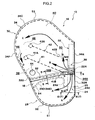
- Fig. 1 to Fig. 3 relate to a side airbag device at which a side airbag device for a vehicle 10 relating to the present exemplary embodiment is mounted at, for example, a side portion of a seatback 14 of a vehicle seat 12.
- the side airbag device for a vehicle 10 includes a side airbag 16, a partition wall 18, an inflator 22 and a check valve 24.
- the side airbag 16 is constituted to be supplied with gas from the inflator 22 at the time of a side collision, and to inflate and expand at the side of a vehicle occupant 26 sitting on the vehicle seat 12.
- the side airbag 16 includes a lower chamber 28, serving as an example of a high-pressure chamber that is at a higher pressure during inflation and expansion, and an upper chamber 30, serving as an example of a low-pressure chamber that is at a lower pressure than the high-pressure chamber.
- the lower chamber 28 and the upper chamber 30 both inflate and expand.
- the lower chamber 28 is formed by a lower fabric 32, is an inflating portion that is disposed at the seat lower side of the side airbag 16 in the inflated and expanded state, and corresponds with a waist area 26W of the occupant 26 sitting on the vehicle seat 12.
- the lower chamber 28 is formed by an outer side fabric 32A of the lower fabric 32, which is disposed at the seat width direction outer side with respect to the vehicle seat 12, and an inner side fabric 32B, which is disposed at the seat width direction inner side, being folded in two to the seat forward side about a seat rearward end portion 32R of the lower fabric 32 and sewn together at a periphery edge portion 32C (a sewn portion S1).
- a coating may be applied to the inner face of the lower fabric 32.
- An upper fabric 34 constitutes the upper chamber 30.
- a lower region of the upper fabric 34 is used as the partition wall 18.
- An upper end portion 32U of the lower fabric 32 is sewn (a sewn portion S2) to a bag outer face side of an upper end of the lower region of the upper fabric 34.
- the upper end portion 32U of the lower fabric 32 is sewn to the upper fabric 34 with the upper end portion 32U folded over and the thickness increased, in order to reinforce the sewn portion S2.
- This reinforcement is not limited to folding of the upper end portion 32U and may have, for example, a separate member for reinforcement being superimposed and sewn on.
- the upper chamber 30 is constituted by the upper fabric 34, and is an inflating portion that is disposed at the seat upward side of the side airbag 16 in the inflated and expanded state.
- the upper chamber 30 corresponds with one or both of a chest area 26C and a shoulder area 26S of the occupant 26 sitting on the vehicle seat 12.
- the upper chamber 30 corresponds with both the chest area 26C and the shoulder area 26S of the occupant 26, and also corresponds with an upper arm area 26U and an abdomen area 26A.
- the upper chamber 30 is formed by an outer side fabric 34A of the upper fabric 34, which is disposed at the seat width direction outer side with respect to the vehicle seat 12, and an inner side fabric 34B, which is disposed at the seat width direction inner side, being folded in two toward the seat forward side about a seat rearward end portion 34R of the upper fabric 34 and sewn together at a periphery edge portion 34C (a sewn portion S3).
- the partition wall 18 is provided in the side airbag 16 and is a portion that partitions the lower chamber 28 that is the high-pressure chamber from the upper chamber 30 that is the low-pressure chamber.
- the partition wall 18 is formed by sewing together (a sewn portion S4), of the upper fabric 34 constituting the upper chamber 30, a lower end 34D of the outer side fabric 34A disposed at the seat width direction outer side with respect to the vehicle seat 12 and a lower end 34E of the inner side fabric 34B disposed at the seat width direction inner side.
- the partition wall 18 is provided at a location of the side airbag 16 that, in the inflated and expanded state, corresponds with the abdomen area 26A of the occupant 26 sitting on the vehicle seat 12.
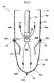
- the inflator 22 is a gas generation source that is disposed in the upper chamber 30 that is the low-pressure chamber, with a gas discharge section 22A facing the lower chamber 28 that is the high-pressure chamber, supplies gas for inflation mainly to the lower chamber 28, and also supplies the gas for inflation to the upper chamber 30.
- the inflator 22 is disposed in the side airbag 16 at the seat rearward side with respect to the vehicle seat 12, specifically in the vicinity of a seat rearward end portion.
- the inflator 22 is connected to an airbag electronic control unit (ECU) via a wire harness, and is constituted to be operated by an operating current from the airbag ECU and supply gas for inflation to the side airbag 16.
- the airbag ECU causes the operation current to flow to the inflator 22 when the airbag ECU identifies a side collision in accordance with a signal from a collision sensor (not illustrated).
- a diffuser 36 is disposed at the gas discharge section 22A of the inflator 22.
- the diffuser 36 is formed in, for example, a tubular shape, and is provided with a first aperture portion 36A that opens toward the lower chamber 28 and a second aperture portion 36B that opens toward the upper chamber 30 in, for example, the seat forward direction.
- the diffuser 36 is constituted to restrict flows of the gas discharged from the gas discharge section 22A of the inflator 22.
- the gas mainly flows through the first aperture portion 36A into the lower chamber 28, and is also distributed through the second aperture portion 36B to the upper chamber 30. As illustrated in Fig.
- an opening area of the first aperture portion 36A of the diffuser 36 is specified to be larger than an opening area of the second aperture portion 36B. Structural examples of the diffuser 36 and mounting thereof to the inflator 22 are described below.
- a first seam 41 is provided that extends, for example, in a straight line forward with respect to the seat and diagonally upward from the diffuser 36 side thereof.
- the first seam 41 is an example of a first bag thickness regulation portion.
- the outer side fabric 34A of the upper fabric 34 constituting the upper chamber 30 and the inner side fabric 34B disposed at the seat width direction inner side are sewn together.
- the first seam 41 partitions the upper chamber 30 between a middle chamber 38 at the seat lower side thereof and an uppermost chamber 40 at the seat upper side thereof.
- a vent hole 44 is formed in a portion of the upper fabric 34 that constitutes the middle chamber 38.
- An inner pressure of the middle chamber 38 during inflation and expansion of the side airbag 16 is set to a lower pressure than that of the uppermost chamber 40.
- a predetermined constriction gap 46 is formed between a seat forward side distal end portion 41 A of the first seam 41 and a seat forward side periphery edge portion 34F of the upper fabric 34 of the upper chamber 30.
- a seat rearward side distal end portion 41B of the first seam 41 is specified to be at, for example, a location near the partition wall 18. This is in order to restrict the gas, which is discharged through the second aperture portion 36B of the diffuser 36 when the side airbag 16 inflates and expands, from flowing into the middle chamber 38 through the gap between the seat rearward side distal end portion 41 B of the first seam 41 and the partition wall 18 and raising the inner pressure of the middle chamber 38 more than is required.
- a second seam 42 at which the outer side fabric 34A and the inner side fabric 34B are sewn together is provided in the upper chamber 30 at the seat upper side with respect to the first seam 41.
- the second seam 42 extends in, for example, a straight line to the seat forward side and diagonally upward from the diffuser 36 side thereof, with a predetermined spacing from the first seam 41.
- the second seam 42 is an example of a second bag thickness restriction portion.
- the second seam 42 is disposed in the uppermost chamber 40 of the upper chamber 30.
- the outer side fabric 34A and inner side fabric 34B are sewn together at the second seam 42.
- a seat forward side distal end portion 42A of the second seam 42 is set to a location corresponding with the upper arm area 26U and/or shoulder area 26S ( Fig. 1 ) of the occupant 26.
- a gap 48 between the seat forward side distal end portion 42A and the seat forward side periphery edge portion 34F of the upper fabric 34 is specified to be larger than the predetermined constriction gap 46 between the seat forward side distal end portion 41A of the first seam 41 and the seat forward side periphery edge portion 34F.
- a gap 50 between a seat rearward side distal end portion 42B of the second seam 42 and the inflator 22 is also specified to be larger than the predetermined constriction gap 46.
- the seat forward side distal end portion 41A of the first seam 41 and the seat forward side distal end portion 42A of the second seam 42 both have circular shapes, but shapes of these distal end portions are not limited thus.
- the shapes of the first seam 41 and the second seam 42 are not limited to being straight lines, and may be curves, inflected lines or the like.
- the first seam 41 that is a sewn portion is offered as an example of the first bag thickness regulation portion
- the second seam 42 that is a sewn portion is offered as an example of the second bag thickness regulation portion.
- the first bag thickness regulation portion and the second bag thickness regulation portion are not limited to being sewn portions.
- the outer side fabric 34A and inner side fabric 34B of the upper fabric 34 may be portions that are joined by, for example, adhesion, welding or the like.
- the check valve 24 is a portion that is provided at the partition wall 18, permits the gas discharged through the gas discharge section 22A of the inflator 22 to flow from the upper chamber 30 that is the low-pressure chamber to the lower chamber 28 that is the high-pressure chamber, and restricts a flow of gas in the opposite direction ( Fig. 4 ).
- This check valve 24 is disposed at the seat rearward side of the interior of the side airbag 16, specifically at the seat rearward end portion of the partition wall 18, and is formed in a tubular shape by the upper fabric 34 being extended to the seat downward side. As illustrated in Fig.
- the lower ends 34D and 34E of the outer side fabric 34A and the inner side fabric 34B are joined to a front edge 24A of the check valve 24.
- the front edge 24A is superposed and folded over with the outer side fabric 34A and inner side fabric 34B, and is sewn up in a four-layer condition.
- the check valve 24 is formed into the tubular shape.
- the check valve 24 is opened by the pressure of the gas.
- the outer side fabric 34A and inner side fabric 34B of the upper fabric 34 that constitute the check valve 24 open up into the tubular shape.
- a lower end portion 24D of the check valve 24 is at least partially sewn to the lower fabric that constitutes the lower chamber 28 (a sewn portion S5).
- a sewn portion S5 for example, rear end corner portions of the lower end portion 24D of the check valve 24 are sewn to the seat rearward end portion 32R of the lower fabric 32.
- a reinforcement cloth 52 may be superposed with and sewn to the check valve 24, in order to further improve strength of the check valve 24 with respect to the high-temperature, high-pressure gas that is discharged from the gas discharge section 22A of the inflator 22.
- the reinforcement cloth 52 is superposed with and sewn to the inner periphery side of the check valve 24, and the front edge 24A of the check valve 24 is superposed and folded over with the outer side fabric 34A, the inner side fabric 34B and the reinforcement cloth 52, and is sewn up in a six-layer condition.
- the reinforcement cloth 52 may be superposed with the outer periphery of the check valve 24.
- each chamber 28 of the side airbag 16 is formed by sewing the periphery edge portion 32C of the lower fabric 32 and the upper chamber 30 is formed by sewing the periphery edge portion 34C of the upper fabric 34, but this is not a limitation.
- each chamber may be formed by hollow weaving.
- Fig. 6 is a magnified sectional diagram taken along arrows 6-6 of Fig. 2 .
- the check valve 24 portion is not actually in a sectional view but hatching is applied thereto in order to clearly indicate superposition of the layers. The same applies to the check valve 24 and the reinforcement cloth 52 in Fig. 7 .
- the diffuser 36 relating to a first structural example is formed in a circular tube shape with a length and inner diameter into which at least a portion of the inflator 22, from the gas discharge section 22A to a position of a stud bolt 54 at the gas discharge section 22A side, may be inserted.
- the first aperture portion 36A is formed in a floor portion 36D
- the second aperture portion 36B is formed at, for example, one location of an outer periphery portion 36C.
- the first aperture portion 36A and the second aperture portion 36B are, for example, both formed in circular shapes.
- the second aperture portion 36B is disposed at the radial direction outer side, at the seat forward side of the inflator 22 (see Fig. 2 ).
- two of the stud bolt 54 are provided standing from the inflator 22, extending to the seat width direction inner side.
- the stud bolts 54 are passed through a seatback frame 56 in the seatback 14 and nuts 58 are fastened onto the stud bolts 54.
- the inflator 22, together with the side airbag 16 is fixed to the seatback frame 56.
- the opening direction of the second aperture portion 36B of the diffuser 36 is to the seat forward side, which is orthogonal to the axial direction of the stud bolts 54.
- a pair of cut-and-lifted portions 36E that extend to the radial direction outer side of the diffuser 36 are formed in the outer periphery portion 36C of the diffuser 36.
- a slit 36S is formed between the pair of cut-and-lifted portions 36E.
- the slit 36S is wider than an outer diameter of the stud bolt 54, is longer to the floor portion 36D side than the cut-and-lifted portions 36E ( Fig. 8 ), and opens out at an end portion 36F at the opposite end of the slit 36S from the end at which the floor portion 36D is provided.
- a recess 36G that is, for example, semi-circular is formed to match the outer diameter of the stud bolt 54.
- the diffuser 36 is mounted to the inflator 22 in the axial direction to cover the inflator 22.
- the stud bolt 54 that is at the gas discharge section 22A side passes along the slit 36S of the diffuser 36.
- the inflator 22 is inserted into the diffuser 36 until the stud bolt 54 engages with the recess 36G.
- the slit 36S is closed by the pair of cut-and-lifted portions 36E being folded down in the directions of the respective arrows K so as to be in line with the outer periphery portion 36C and are caulked.
- mounting of the diffuser 36 to the inflator 22 is completed.
- the diffuser 36 relating to a second structural example is basically the same as the first structural example but differs from the first structural example in that the cut-and-lifted portion 36E is formed at only one side of the slit 365. This cut-and-lifted portion 36E extends to the radial direction outer side of the diffuser 36 and matches the width of the slit 36S.
- the inflator 22 When the diffuser 36 is being mounted to the inflator 22, the inflator 22 is inserted into the diffuser 36 until the stud bolt 54 engages with the recess 36G. Then, the cut-and-lifted portion 36E is folded down in the direction of arrow K so as to be in line with the outer periphery portion 36C and is caulked. Thus, the slit 36S is closed and mounting of the diffuser 36 to the inflator 22 is completed.
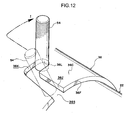
- the diffuser 36 relating to a third structural example includes an axial direction portion 36J that extends in the axial direction of the diffuser 36 and a circumferential direction portion 36K that extends in the circumferential direction of the diffuser 36 from the end portion of the axial direction portion 36J and comes to a terminal end.
- the shape of the slit 36S is a substantial letter "L" shape.
- the inflator 22 When the diffuser 36 is being mounted to the inflator 22, firstly, the inflator 22 is inserted into the diffuser 36 such that the stud bolt 54 passes along the axial direction portion 36J of the slit 36S. Then, the inflator 22 is turned in the circumferential direction of the diffuser 36 (the direction of arrow I) such that the stud bolt 54 passes along the circumferential direction portion 36K of the slit 36S. When the stud bolt 54 reaches an end portion 36L of the circumferential direction portion 36K, mounting of the diffuser 36 to the inflator 22 is completed.
- the width of the circumferential direction portion 36K may be partially made narrower than the outer diameter of the stud bolt 54 so as to provide a sensation of resistance when the stud bolt 54 reaches the end portion 36L of the circumferential direction portion 36K.
- the shape of the circumferential direction portion 36K may be structured as a taper shape whose width narrows toward the end portion 36L such that the stud bolt 54 fits to the circumferential direction portion 36K with no gap when reaching the end portion 36L of the circumferential direction portion 36K.
- the circumferential direction portion 36K may be angled with respect to the circumferential direction of the diffuser 36 such that an angle formed in the slit 36S between the axial direction portion 36J and the circumferential direction portion 36K is an acute angle.
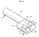
- the diffuser 36 relating to a fourth structural example is constituted in an elongated-circular tube shape with a length into which at least a portion of the inflator 22, from the gas discharge section 22A to the position of the stud bolt 54 at the gas discharge section 22A side, may be inserted.
- the outer diameter of the inflator 22 is represented by D and an amount of protrusion of the stud bolt 54 is represented by L
- an inner diameter d1 in the long axis direction of the diffuser 36 is specified such that d1>D+L
- an inner diameter d2 in the short axis direction of the diffuser 36 is specified such that d2>D. Therefore, as illustrated in Fig.
- the stud bolt 54 may also be accommodated and inserted.
- Upper limits on the inner diameters d1 and d2 are suitably specified to take account of space for mounting of the side airbag device for a vehicle 10 at a side portion of the seatback 14.
- a slit 36M is formed in the outer periphery portion 36C of the diffuser 36.
- the slit 36M extends in the circumferential direction of the outer periphery portion 36C, and the stud bolt 54 at the gas discharge section 22A side may pass along the slit 36M. If the long axis direction of the diffuser 36 is taken to be the vertical direction on the paper of the drawing, the slit 36M is formed, for example, in a range of approximately 90°, roughly from the six o'clock position to the nine o'clock position. In this case, the second aperture portion 36B is formed in a substantially rectangular shape at the 12 o'clock position. As illustrated in Fig.
- the first aperture portion 36A is formed in, for example, an elongated circle shape, which is the shape of the end portion of the diffuser 36.
- an opening is formed between the inflator 22 and the diffuser 36.
- An unillustrated cap or the like may be attached in order to close off or narrow this opening at the end portion 36F.
- Fig. 14 when the diffuser 36 is being mounted to the inflator 22, a portion of the gas discharge section 22A side of the inflator 22 is inserted into the diffuser 36 together with the stud bolt 54 at the gas discharge section 22A side. At this time, as illustrated by the two-dot chain lines, the inflator 22 is disposed toward the upper side on the paper surface (the 12 o'clock position). Thus, interference between the stud bolt 54 and the diffuser 36 may be inhibited.
- the inflator 22 is moved downward along the paper surface relative to the diffuser 36 (in the direction of arrow J), and the stud bolt 54 at the gas discharge section 22A side is inserted into the slit 36M.
- the diffuser 36 is relatively turned through 90° in the direction of arrow R with respect to the inflator 22.
- the stud bolt 54 relatively moves in the slit 36M.
- the inflator 22 and the diffuser 36 are disposed inside the side airbag 16 in this state, and fixed by fastening to the seatback frame 56 along with the side airbag 16.
- the opening direction of the second aperture portion 36B of the diffuser 36 is to the seat forward side, and is orthogonal to the axial direction of the stud bolts 54. Because the short axis direction of the diffuser 36 is in the seat width direction, an amount of protrusion of the diffuser 36 in the seat width direction is the same as with the diffusers 36 relating to the first to third structural examples (see Fig. 9 ).
- the stud bolt 54 is engaged with the slit 36M of the diffuser 36 in the axial direction of the inflator 22. Therefore, without the diffuser 36 being separated from the inflator 22 by the pressure of the gas during operation of the inflator 22, the gas for inflating may be mainly supplied through the first aperture portion 3 6A toward the lower chamber 28 (see Fig. 2 ) and the gas may also be supplied through the second aperture portion 36B to the upper chamber 30 of the side airbag 16 in the directions of the arrows B.
- Numbers, shapes and positions of the first aperture portions 36A and second aperture portions 36B of the diffusers 36 relating to the above structural examples are not limited to those illustrated.
- the present exemplary embodiment is constituted as described above, and operations thereof are described herebelow.
- a reclining mechanism (not illustrated) is often provided at the vehicle seat 12 for adjusting an inclination angle of the seatback 14, and it is difficult to guarantee installation space for an airbag module at a lower portion of the side portion of the seatback 14.
- the inflator 22 is disposed in the side airbag 16 at the seat rearward side and is disposed in the upper chamber 30 that is the low-pressure chamber.
- folded dimensions (package dimensions) of the side airbag 16 may be reduced. Therefore, installation characteristics of an airbag module (not illustrated) at the side portion of the seatback 14 are excellent.
- the lower chamber 28 that is the high-pressure chamber and the lower chamber 28 that is the low-pressure chamber are partitioned by the partition wall 18.
- This partition wall 18 is formed by sewing together, of the upper fabric 34 that constitutes the upper chamber 30, the lower end 34D of the outer side fabric 34A disposed at the seat width direction outer side with respect to the vehicle seat 12 and the lower end 34E of the inner side fabric 34B disposed at the seat width direction inner side.
- the check valve 24 is provided at the partition wall 18. The check valve 24 is disposed at the seat rearward side of the interior of the side airbag 16, and is formed by the upper fabric 34 extending to the seat downward side.
- the operation current is caused to flow from the airbag ECU to the inflator 22.
- the inflator 22 receives the operation current and operates, and a large quantity of gas is discharged through the gas discharge section 22A. This gas is supplied into the side airbag 16.
- the side airbag 16 inflates from the seatback 14, and inflates and expands between the vehicle side (not illustrated) and the occupant 26.
- the inflator 22 is disposed in the upper chamber 30 that is the low-pressure chamber with the gas discharge section 22A facing the lower chamber 28 that is the high-pressure chamber.
- the diffuser 36 is disposed at the gas discharge section 22A of the inflator 22, and the first aperture portion 36A that opens toward the lower chamber 28 and the second aperture portion 36B that opens toward the upper chamber 30 are formed in the diffuser 36. Flows of the gas may be restricted by this diffuser 36 such that the gas discharged from the gas discharge section 22A mainly passes through the first aperture portion 36A and flows toward the lower chamber 28, and also passes through the second aperture portion 36B and is distributed to the upper chamber 30.
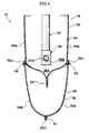
- the check valve 24 is opened in a tubular shape by pressure of the gas that passes through the first aperture portion 36A of the diffuser 36 and is supplied from the inflator 22 in the upper chamber 30 toward the lower chamber 28, and permits the gas to flow into the lower chamber 28 in the directions of the arrows A. Meanwhile, gas passes through the second aperture portion 36B of the diffuser 36 and is supplied in the directions of the arrows B into the upper chamber 30 too. Because the opening area of the first aperture portion 36A of the diffuser 36 is specified to be larger than the opening area of the second aperture portion 36B, the gas for inflation is supplied with precedence to the lower chamber 28 rather than the upper chamber 30.
- the lower chamber 28 inflates and expands more promptly than the upper chamber 30, and has a higher pressure than the upper chamber 30.
- the lower chamber 28 and the upper chamber 30 may both be stably inflated and expanded with a simple structure in which the diffuser 36 is added.
- the check valve 24 closes and the flow of gas is restricted. Therefore, the inner pressure of the lower chamber 28 may be maintained for a longer time.
- the lower end portion 24D of the check valve 24 is at least partially sewn (sewn portion S5) to the lower fabric 32 that constitutes the lower chamber 28.
- the upper chamber 30 is partitioned by the first seam 41 into the middle chamber 38 at the seat lower side thereof and the uppermost chamber 40 at the seat upper side.
- the gas for inflation that is supplied through the second aperture portion 36B of the diffuser 36 is first supplied in the directions of the arrows B into the uppermost chamber 40, and then proceeds to flow in the direction of arrow C.
- the uppermost chamber 40 proceeds to inflate and expand.
- the bag thickness of the upper chamber 30 is regulated by the first seam 41.
- the second seam 42 is provided in the uppermost chamber 40 of the upper chamber 30 and the bag thickness of the uppermost chamber 40 is regulated by the second seam 42.
- the uppermost chamber 40 may be promptly and smoothly inflated and expanded in the limited space between the upper body of the occupant 26, particularly the shoulder area 26S and upper arm area 26U that protrude furthest to the seat outer side, and the vehicle side. Restraining forces on the shoulder area 26S, the chest area 26C and the upper arm area 26U, which is a region corresponding with the uppermost chamber 40, may be optimized.
- the gas supplied into the uppermost chamber 40 passes through the constriction gap 46 between the seat forward side distal end portion 41 A of the first seam 41 and the seat forward side periphery edge portion 34F of the upper fabric 34, and is supplied in the direction of arrow D into the middle chamber 38. Therefore, the timing of inflation and expansion of the middle chamber 38 is later than that of the uppermost chamber 40.
- the vent hole 44 is formed in the portion of the upper fabric 34 that constitutes the middle chamber 38.
- the lower chamber 28 that is the high-pressure chamber corresponds with the waist area 26W of the occupant 26 and the upper chamber 30 that is the low-pressure chamber corresponds with the chest area 26C, shoulder area 26S, upper arm area 26U and abdomen area 26A of the occupant 26.
- the lower chamber 28 inflates and expands prior to the upper chamber 30, and the lower chamber 28 has a higher pressure than the upper chamber 30. Therefore, the waist area 26W of the occupant 26 sitting on the vehicle seat 12 may be restrained more promptly and with a higher pressure by the lower chamber 28.
- the inner pressure of the lower chamber 28 may be maintained for a longer time because of the check valve 24, and occupant restraint performance in a side collision may be further improved.
- the chest area 26C, shoulder area 26S, upper arm area 26U and abdomen area 26A of the occupant 26 may be restrained by the upper chamber 30 of the side airbag 16.
- the chest area 26C and shoulder area 26S of the occupant 26 may be restrained by the uppermost chamber 40 of the upper chamber 30, and mainly the abdomen area 26A may be restrained by the middle chamber 38.
- the middle chamber 38 is set to a lower pressure than the uppermost chamber 40, a restraining force on the abdomen area 26A by the middle chamber 38 may be made weaker than a restraining force on the shoulder area 26S and the chest area 26C or the like by the uppermost chamber 40.
- respective portions of the upper body of the occupant 26 may be restrained with respectively appropriate restraining forces by the upper chamber 30 of the side airbag 16.
- the check valve 24 is constituted by a rear end portion 18R of the partition wall 18 and a rear side inner face 16R of the side airbag 16.
- a flow path for the gas is opened up by the rear end portion 18R of the partition wall 18 moving away from the rear side inner face 16R, and the flow path for the gas is closed off by the rear end portion 18R abutting against the rear side inner face 16R.
- the present example is formed by, for example, a single fabric 60 being folded in two to the seat forward side about a seat rearward end portion 60R and, as illustrated in Fig. 19 , an outer side fabric 60A disposed at the seat width direction outer side and an inner side fabric 60B disposed at the seat width direction inner side being sewn together at a periphery edge portion 60C (a sewn portion S6).
- the partition wall 18 is structured as a separate member from the side airbag 16.
- the inner face of the fabric 60 of the side airbag 16 is sewn to edge portions 18A at the two seat width direction sides of the partition wall 18 (sewn portions S7).
- slackness at the time of inflation and expansion of the side airbag 16 is set to be greater than the partition wall 18. Therefore, the check valve 24 protrudes to the seat downward side because of the pressure of the gas being supplied through the first aperture portion 36A of the diffuser 36 toward the lower chamber 28, is opened up by the rear end portion 18R of the partition wall 18 moving away from the rear side inner face 16R of the side airbag 16, and permits the flow of gas in the directions of the arrows A from the upper chamber 30 into the lower chamber 28.
- the check valve 24 tries to invert to the seat upward side.
- the rear end portion 18R of the partition wall 18 makes surface contact with the rear side inner face 16R of the side airbag 16 and the check valve 24 closes.
- the edge portions 18A of the partition wall 18 are angled to the seat downward side toward the seat rearward side in the region of the check valve 24, and angles 0 formed between the edge portions 18A and the rear side inner face 16R of the side airbag 16 are set to, for example, less than 90°. Therefore, when the check valve 24 is closing, the rear end portion 18R of the partition wall 18 easily makes surface contact with the rear side inner face 16R.
- the first seam 41 and the second seam 42 are provided at the portion of the fabric 60 that constitutes the upper chamber 30.
- the predetermined constriction gap 46 is provided between the seat forward side distal end portion 41A of the first seam 41 and a seat forward side periphery edge portion 60F of the fabric 60 of the upper chamber 30.
- the gap 48 is provided between the seat forward side distal end portion 42A of the second seam 42 and the seat forward side periphery edge portion 60F, and is specified to be larger than the predetermined constriction gap 46.
- the structures described in the above-mentioned first to fourth structural examples may be used as appropriate.
- the side airbag 16 is formed by sewing the periphery edge portion 60C of the fabric 60, but this is not a limitation.
- the side airbag 16 may be formed by hollow weaving.
- the present example is constituted as described above, and operations thereof are described herebelow.
- the operation current is caused to flow from the airbag ECU to the inflator 22.
- the inflator 22 receives the operation current and operates, and a large quantity of gas is discharged through the gas discharge section 22A. This gas is supplied into the side airbag 16.
- the side airbag 16 inflates from the seatback 14, and inflates and expands between the vehicle side (not illustrated) and the occupant 26 (see Fig. 1 )
- the check valve 24 opens so as to protrude to the lower side because of the pressure of the gas that passes through the first aperture portion 36A of the diffuser 36 and is supplied from the inflator 22 in the upper chamber 30 toward the lower chamber 28 in the directions of arrows A, and the check valve 24 permits the gas to flow into the lower chamber 28 in the directions of arrows A. Meanwhile, gas passes through the second aperture portion 36B of the diffuser 36 and is supplied in the directions of the arrows B into the upper chamber 30 too.
- the gas for inflation is supplied with precedence to the lower chamber 28 rather than the upper chamber 30. Therefore, the lower chamber 28 inflates and expands more promptly than the upper chamber 30 and has a higher pressure than the upper chamber 30.
- the inflation and expansion of the upper chamber 30 is the same as in the first exemplary embodiment, so is not described.
- the edge portions 18A of the partition wall 18 are angled to the seat downward side toward the seat rearward side in the region of the check valve 24, and the angles ⁇ formed between the edge portions 18A and the rear side inner face 16R of the side airbag 16 are set to, for example, less than 90°. Therefore, when the check valve 24 is closing, the rear end portion 18R of the partition wall 18 easily makes surface contact with the rear side inner face 16R. The check valve 24 is inhibited from inverting and opening to the seat upward side by the rear end portion 18R of the partition wall 18 making surface contact with the rear side inner face 16R. Therefore, the inner pressure of the lower chamber 28 that is the high-pressure chamber may be stably maintained.
- the waist area 26W of the occupant 26 sitting on the vehicle seat 12 may be restrained promptly and with a high pressure by the lower chamber 28 that is the high-pressure chamber.
- respective portions of the upper body of the occupant 26 may be restrained with respectively appropriate restraining forces by the upper chamber 30 that is the low-pressure chamber.
- first seam 41 and the second seam 42 are provided in the upper chamber 30 of the side airbag 16, but this is not a limitation. Structures are possible in which only the second seam 42 is not provided, and structures are possible in which neither of the first seam 41 and the second seam 42 is provided.
Landscapes
- Engineering & Computer Science (AREA)
- Mechanical Engineering (AREA)
- Physics & Mathematics (AREA)
- Fluid Mechanics (AREA)
- Air Bags (AREA)
Description
- The present invention relates to a side airbag device for a vehicle.
- A structure has been disclosed (see Patent Reference 1) in which the interior of an airbag for side impacts is partitioned into an upper chamber and a lower chamber by a seam, a communication portion that communicates between the upper chamber and the lower chamber is formed between the seam and a rear edge of the airbag, a tubular check valve is provided at the communication portion, a gas generator is disposed in the check valve, and an outflow of gas from the lower chamber to the upper chamber is impeded by the check valve. Thus, even if the body of a vehicle occupant strikes the lower chamber, gas pressure in the lower chamber is maintained at a high pressure.
- Patent Reference 1: Japanese Patent Application Laid-Open (JP-A) No.
2004-256017 - Further Prior Art:
US 2007/284859 A1 , which discloses a side airbag device according to the preamble ofclaim 1. - However, the related art example mentioned above has a structure in which the check valve is inflated in a substantially tubular shape and a high-pressure portion is formed by gas being discharged radially from an end portion of the gas generator, and the gas is supplied to each of the upper chamber and the lower chamber using pressure differences between the high-pressure portion and the upper chamber and lower chamber. Therefore, it is necessary for the check valve to have the tubular shape. Moreover, in order to restrict the passage of gas around the check valve between the upper chamber and the lower chamber, side edges at the airbag front side of the check valve must be sewn to the seam or the like partitioning the upper chamber and lower chamber, and it is difficult to guarantee a bag thickness of the airbag in the region dividing the upper and lower chambers.
- In consideration of the above circumstances, an object of the present invention is, with a simple structure, to promptly inflate and expand a high-pressure chamber of a side airbag and to allow the pressure in the high-pressure chamber to be maintained for a long-time.
- The present invention includes: a side airbag that includes a high-pressure chamber, which has a high pressure at a time of inflation and expansion, and a low-pressure chamber, which has a lower pressure than the high-pressure chamber, the high-pressure chamber and the low-pressure chamber each inflating and expanding at a time of side collision; a partition wall that is disposed in the side airbag and partitions the high-pressure chamber from the low-pressure chamber; an inflator that is disposed in the low-pressure chamber in a state in which a gas discharge section faces the high-pressure chamber and is disposed at the low-pressure chamber side relative to the partition wall, that supplies gas for inflation mainly toward the high-pressure chamber and that also supplies the gas for inflation to the low-pressure chamber; and a check valve that is disposed at the partition wall, that permits the gas discharged from the gas discharge section of the inflator to flow from the low-pressure chamber to the high-pressure chamber, and that restricts a flow of the gas in the opposite direction.
- In the side airbag device for a vehicle relating to the invention, the side airbag includes the high-pressure chamber that has a high pressure during inflation and expansion and the low-pressure chamber that has a lower pressure than the high-pressure chamber, and the inflator is disposed in the low-pressure chamber with the gas discharge section facing the high-pressure chamber and being disposed at the low-pressure chamber side relative to the partition wall. When there is a side collision, the inflator operates and the gas for inflation that is discharged from the gas discharge section of the inflator is supplied mainly to the high-pressure chamber, and is also supplied to the low-pressure chamber of the side airbag.
- The high-pressure chamber and low-pressure chamber are partitioned by the partition wall. The check valve provided at the partition wall is opened by the pressure of the gas supplied from the inflator in the low-pressure chamber toward the high-pressure chamber, and allows the gas to flow from the low-pressure chamber into the high-pressure chamber. Thus, the gas is supplied with precedence to the high-pressure chamber, and the high-pressure chamber promptly inflates and expands and has a higher pressure than the low-pressure chamber. When the inflator completes the discharge of the gas, the gas tries to flow back from the high-pressure chamber to the low-pressure chamber, but the check valve restricts such flow of the gas. Hence, the inner pressure of the high-pressure chamber may be maintained for a long time.
- An aspect of the present invention is the side airbag device for a vehicle in which, in the side airbag in an inflated and expanded state, the inflator is disposed in the side airbag at a seat rearward side with respect to a vehicle seat, the partition wall is disposed at a position that corresponds with an abdomen area of an occupant sitting on the vehicle seat, the high-pressure chamber is a lower chamber that corresponds with a waist area of the occupant, and the low-pressure chamber is an upper chamber that corresponds with at least one of a chest area or a shoulder area of the occupant.
- In the side airbag device for a vehicle relating to that aspect, the high-pressure chamber is the lower chamber corresponding with the waist area of an occupant, and the low-pressure chamber is the upper chamber corresponding with one or both of the chest area and shoulder area of the occupant. Thus, because the lower chamber inflates and expands prior to the upper chamber and the lower chamber has a higher pressure than the upper chamber when the side airbag inflates and expands, the waist area of the occupant sitting on the vehicle seat may be restrained by the lower chamber promptly and at a high pressure, and one or both of the chest area and shoulder area of the occupant may be restrained by the upper chamber. Moreover, the inner pressure of the lower chamber may be maintained for a long time because of the check valve, and thus occupant restraint performance in a side collision may be further improved.
- An aspect of the present invention is the side airbag device for a vehicle in which the partition wall is formed by sewing together, of an upper fabric that constitutes the upper chamber, a lower edge of an outer side fabric that is disposed at a seat width direction outer side with respect to the vehicle seat and a lower edge of an inner side fabric that is disposed at the seat width direction inner side, and the check valve is disposed at the seat rearward side in the side airbag, and is formed by extending the upper fabric to a seat downward side.
- In the side airbag device for a vehicle relating to that aspect, the partition wall is formed by sewing, of the upper fabric that structures the upper chamber, a lower edge of the outer side fabric disposed at the seat width direction outer side of the vehicle seat to a lower edge of the inner side fabric disposed at the seat width direction inner side. The check valve is disposed at the seat rearward side of the side airbag interior, and is formed by the upper fabric being extended to the seat downward side. Thus, there is no need to add the partition wall and/or the check valve separately from the fabrics structuring the side airbag. Therefore, sewing in order to improve airtightness may be omitted, fabrication of the side airbag is simple, and a large reduction in costs may be promoted.
- A further aspect of the present invention is the side airbag device for a vehicle in which a reinforcement cloth is superposed with and sewn to the check valve.
- In the side airbag device for a vehicle relating to that aspect, the reinforcement cloth is superposed with and sewn to the check valve. Thus, strength with respect to the high-temperature, high-pressure gas that is supplied toward the check valve from the gas discharge section of the inflator may be improved.
- A further aspect of the present invention is the side airbag device for a vehicle in which a lower end portion of the check valve is at least partially sewn to a lower fabric that constitutes the lower chamber.
- In the side airbag device for a vehicle relating to that aspect, the lower end portion of the check valve is at least partially sewn to the lower fabric that structures the lower chamber. Thus, when the discharge of gas from the inflator is completed and the gas tries to flow back from the lower chamber that is the high-pressure chamber to the upper chamber that is the low-pressure chamber and the check valve closes, an inversion of the check valve into the upper chamber may be inhibited. Therefore, the inner pressure of the high-pressure chamber may be stably maintained.
- A further aspect of the present invention is the side airbag device for a vehicle in which a diffuser is disposed at the gas discharge section of the inflator, in which diffuser a first aperture portion that opens toward the lower chamber and a second aperture portion that opens toward the upper chamber are provided, the diffuser regulating flows of the gas such that the gas discharged from the gas discharge section mainly flows toward the lower chamber and is also distributed to the upper chamber.
- In the side airbag device for a vehicle relating to that aspect, the diffuser is disposed at the gas discharge section of the inflator, and the first aperture portion opening toward the lower chamber and the second aperture portion opening toward the upper chamber are provided at the diffuser. The diffuser may restrict a flow of gas such that the gas discharged through the gas discharge section mainly flows through the first aperture portion into the lower chamber, and is distributed through the second aperture portion to the upper chamber. With a simple structure in which this diffuser is added, both the lower chamber and the upper chamber may be stably inflated and expanded.
- A further aspect of the present invention is the side airbag device for a vehicle in which, in the upper chamber, a first bag thickness regulation portion is provided extending to the seat forward side and diagonally upward from the diffuser side, at which first bag thickness regulation portion, of an upper fabric that constitutes the upper chamber, an outer side fabric that is disposed at the seat width direction outer side with respect to the vehicle seat is sewn to an inner side fabric disposed at the seat width direction inner side, the first bag thickness regulation portion partitioning the upper chamber into a middle chamber at the seat lower side thereof and an uppermost chamber at the seat upper side thereof, the diffuser is set such that the gas discharged from the second aperture portion of the diffuser is supplied to the uppermost chamber and supplied through a predetermined constriction gap to the middle chamber, the predetermined constriction gap being provided between a seat forward side distal end portion of the first bag thickness regulation portion and a seat forward side periphery edge portion of the upper chamber, and an inner pressure of the middle chamber at the time of inflation and expansion of the side airbag is set to a lower pressure than an inner pressure of the uppermost chamber.
- In the side airbag device for a vehicle relating to that aspect, the bag thickness of the upper chamber when the side airbag is inflating and expanding is regulated by the first bag thickness regulation portion. Therefore, the upper chamber of the side airbag may be inflated and expanded promptly and smoothly in the limited space between the upper body of the occupant and a side portion of the vehicle. Furthermore, the upper chamber is partitioned into the uppermost chamber and the middle chamber by the first bag thickness regulation portion. The gas discharged through the second aperture portion of the diffuser is supplied to the uppermost chamber, passes through the predetermined constriction gap that is formed between the seat forward distal end portion of the first bag thickness regulation portion and the seat forward periphery edge portion of the upper chamber, and is supplied into the middle chamber. Therefore, a timing of inflation and expansion of the middle chamber is delayed relative to the uppermost chamber, and the middle chamber is set to a lower pressure than the uppermost chamber. Therefore, respective portions of the upper body of the occupant may be restrained with respectively appropriate restraining forces by the side airbag.
- A further aspect of the present invention is the side airbag device for a vehicle in which a second bag thickness regulation portion is provided in the upper chamber, extending to the seat forward side and diagonally upward from the diffuser side, at the seat upper side of the first bag thickness regulation portion with a predetermined spacing from the first bag thickness regulation portion, at which second bag thickness regulation portion the outer side fabric is sewn to the inner side fabric.
- In the side airbag device for a vehicle relating to that aspect, the bag thickness of the uppermost chamber during inflation and expansion of the side airbag is regulated by the second bag thickness regulation portion. Therefore, the uppermost chamber of the side airbag may be promptly and smoothly inflated and expanded in the limited space between the upper body of the occupant and the vehicle side.
- A further aspect of the present invention is the side airbag device for a vehicle in which a vent hole is formed in a portion of the upper fabric that constitutes the middle chamber.
- In the side airbag device for a vehicle relating to that aspect, the vent hole is formed in the portion of the upper fabric that constitutes the middle chamber. Thus, when a portion of the upper body of the occupant is restrained by the middle chamber, gas is discharged through the vent hole, and the inner pressure of the middle chamber, which is set to a lower pressure than the uppermost chamber, decreases further. Therefore, restraining force of the middle chamber on the occupant may be further weakened.
- As described hereabove, according to a side airbag device for a vehicle according to the present invention, excellent effects are provided in that the high-pressure chamber of the side airbag may be inflated and expanded promptly and in that the inner pressure of the high-pressure chamber may be maintained for a long time.
- According to the side airbag device for a vehicle according to the invention, excellent effects are provided in that the waist area of an occupant sitting on a vehicle seat may be restrained promptly and at a high pressure by the lower chamber, and at least one of a chest area and shoulder area of the occupant may be restrained by the upper chamber.
- According to the side airbag device for a vehicle according to the invention, excellent effects are provided in that sewing in order to improve airtightness may be omitted, fabrication of the side airbag may be simplified, and a large reduction in costs may be promoted.
- According to the side airbag device for a vehicle relating to a further aspect, an excellent effect is provided in that strength with respect to high-temperature, high-pressure gas that is supplied toward the check valve from the gas discharge section of the inflator may be improved.
- According to the side airbag device for a vehicle relating to a further aspect, an excellent effect is provided in that the inner pressure of the high-pressure chamber may be more stably maintained.
- According to the side airbag device for a vehicle relating to a further aspect, an excellent effect is provided in that the lower chamber and the upper chamber may both be stably inflated and expanded with a simple structure in which the diffuser is added.
- According to the side airbag device for a vehicle relating to a further aspect, an excellent effect is provided in that the side airbag may be promptly and smoothly inflated and expanded in the limited space between the occupant and the vehicle side.
- According to the side airbag device for a vehicle relating to a further aspect, an excellent effect is provided in that the uppermost chamber of the side airbag may be promptly and smoothly inflated and expanded in the limited space between the upper body of the occupant and the vehicle side.
- According to the side airbag device for a vehicle relating to a further aspect, an excellent effect is provided in that restraining force of the middle portion on the occupant may be further weakened.
-
-
Fig. 1 to Fig. 12 relate to an exemplary embodiment. -
Fig. 1 is a side elevation illustrating a state in which a side airbag is inflated and expanded to the side of an occupant sitting on a vehicle seat. -
Fig. 2 is a side elevation illustrating a side airbag. -
Fig. 3 is a magnified sectional diagram taken along arrows 3-3 inFig. 2 , illustrating a state during operation of an inflator, in which state a check valve is opened by the pressure of gas discharged through a first aperture portion of a diffuser to a lower chamber and the gas is supplied into the lower chamber, and gas is discharged through a second aperture portion into an upper chamber. -
Fig. 4 is a magnified sectional diagram taken along arrows 4-4 inFig. 2 , illustrating a state in which the discharge of gas from the inflator has been completed and the check valve has closed. -
Fig. 5 is a magnified sectional diagram taken along arrows 5-5 inFig. 2 , illustrating a structure in which the side airbag interior is partitioned into an upper chamber and a lower chamber. -
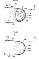
Fig. 6 is a magnified sectional diagram taken along arrows 6-6 inFig. 2 , illustrating a theory of closing of the check valve, with the inflator, the diffuser and a partition wall being omitted from the drawing. -
Fig. 7 is a magnified sectional diagram taken along arrows 7-7 inFig. 2 , illustrating an example in which a reinforcement cloth is superposed with and sewn to the check valve, with the inflator, the diffuser and the partition wall being omitted from the drawing. -
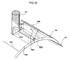
Fig. 8 to Fig. 10 relate to a first structural example of the diffuser. -
Fig. 8 is a perspective diagram illustrating a state in which the diffuser is mounted to an inflator. -
Fig. 9 is a magnified sectional diagram taken along arrows 9-9 inFig. 2 , illustrating a state in which the inflator and the side airbag are fixed by fastening to a seatback frame, and gas from the inflator is supplied through a second aperture portion of the diffuser to the upper chamber. -
Fig. 10 is a magnified perspective diagram illustrating a slit formed in an outer periphery portion of the diffuser being closed, after a stud bolt has been passed along the slit, by a pair of cut-and-lifted portions formed at the two sides of the slit being folded down and caulked. -
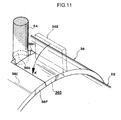
Fig. 11 relates to a second structural example of the diffuser, and is a magnified perspective diagram illustrating a slit formed in an outer periphery portion of the diffuser being closed, after a stud bolt has been passed along the slit, by a cut-and-lifted portion formed at one side of the slit being folded down and caulked. -
Fig. 12 relates to a third structural example of the diffuser, and is a magnified perspective diagram illustrating a stud bolt being passed through and fitted to a substantially L-shaped slit formed in an outer periphery portion of the diffuser. -
Fig. 13 to Fig. 17 relate to a fourth structural example of a diffuser. -
Fig. 13 is a perspective diagram illustrating a state in which the gas discharge section of the inflator is inserted into the diffuser and a stud bolt at the gas discharge section is inserted into a slit. -
Fig. 14 is a magnified sectional diagram taken along arrows 14-14 inFig. 13 , illustrating the state in which the gas discharge section of the inflator is inserted into the diffuser and the stud bolt at the gas discharge section is inserted into the slit. -
Fig. 15 is a perspective diagram illustrating a state in which mounting of the diffuser to the inflator is completed. -
Fig. 16 is a magnified sectional diagram taken along arrows 16-16 inFig. 15 , illustrating the state in which mounting of the diffuser to the inflator is completed. -
Fig. 17 is a sectional diagram, corresponding toFig. 9 , illustrating a state in which the inflator and the side airbag are fixed by fastening to a seatback frame and gas from the inflator is supplied through a second aperture portion of the diffuser to the upper chamber. -
Fig. 18 to Fig. 22 relate to an unclaimed example -
Fig. 18 is a side elevation illustrating a side airbag. -
Fig. 19 is a magnified sectional diagram taken along arrows 19-19 inFig. 18 , illustrating a state during operation of an inflator, in which state a check valve is opened by the pressure of gas discharged through a first aperture portion of a diffuser to a lower chamber and the gas is supplied into the lower chamber, and gas discharged through a second aperture portion is supplied into an upper chamber. -
Fig. 20 is a magnified sectional diagram taken along arrows 20-20 inFig. 18 , illustrating a state in which the check valve is opened. -
Fig. 21 is a magnified sectional diagram taken along arrows 21-21 inFig. 18 , illustrating a state in which the check valve is closed. -
Fig. 22 is a magnified sectional diagram taken along arrows 22-22 inFig. 18 , illustrating a state in which the discharge of gas from the inflator is completed and the check valve is closed. - Herebelow, an exemplary embodiment of the present invention is described on the basis of the attached drawings.
-
Fig. 1 to Fig. 3 relate to a side airbag device at which a side airbag device for avehicle 10 relating to the present exemplary embodiment is mounted at, for example, a side portion of aseatback 14 of avehicle seat 12. The side airbag device for avehicle 10 includes aside airbag 16, apartition wall 18, aninflator 22 and acheck valve 24. - The
side airbag 16 is constituted to be supplied with gas from the inflator 22 at the time of a side collision, and to inflate and expand at the side of avehicle occupant 26 sitting on thevehicle seat 12. Theside airbag 16 includes alower chamber 28, serving as an example of a high-pressure chamber that is at a higher pressure during inflation and expansion, and anupper chamber 30, serving as an example of a low-pressure chamber that is at a lower pressure than the high-pressure chamber. In a side collision, thelower chamber 28 and theupper chamber 30 both inflate and expand. - The
lower chamber 28 is formed by alower fabric 32, is an inflating portion that is disposed at the seat lower side of theside airbag 16 in the inflated and expanded state, and corresponds with awaist area 26W of theoccupant 26 sitting on thevehicle seat 12. Thelower chamber 28 is formed by anouter side fabric 32A of thelower fabric 32, which is disposed at the seat width direction outer side with respect to thevehicle seat 12, and aninner side fabric 32B, which is disposed at the seat width direction inner side, being folded in two to the seat forward side about a seatrearward end portion 32R of thelower fabric 32 and sewn together at aperiphery edge portion 32C (a sewn portion S1). In order to improve airtightness of thelower chamber 28 serving as the high-pressure chamber, a coating may be applied to the inner face of thelower fabric 32. - An
upper fabric 34 constitutes theupper chamber 30. A lower region of theupper fabric 34 is used as thepartition wall 18. Anupper end portion 32U of thelower fabric 32 is sewn (a sewn portion S2) to a bag outer face side of an upper end of the lower region of theupper fabric 34. As illustrated inFig. 3 to Fig. 5 , theupper end portion 32U of thelower fabric 32 is sewn to theupper fabric 34 with theupper end portion 32U folded over and the thickness increased, in order to reinforce the sewn portion S2. This reinforcement is not limited to folding of theupper end portion 32U and may have, for example, a separate member for reinforcement being superimposed and sewn on. - In
Fig. 1 , theupper chamber 30 is constituted by theupper fabric 34, and is an inflating portion that is disposed at the seat upward side of theside airbag 16 in the inflated and expanded state. Theupper chamber 30 corresponds with one or both of achest area 26C and ashoulder area 26S of theoccupant 26 sitting on thevehicle seat 12. In the present exemplary embodiment, theupper chamber 30 corresponds with both thechest area 26C and theshoulder area 26S of theoccupant 26, and also corresponds with anupper arm area 26U and anabdomen area 26A. As illustrated inFig. 1 to Fig. 3 , theupper chamber 30 is formed by anouter side fabric 34A of theupper fabric 34, which is disposed at the seat width direction outer side with respect to thevehicle seat 12, and aninner side fabric 34B, which is disposed at the seat width direction inner side, being folded in two toward the seat forward side about a seatrearward end portion 34R of theupper fabric 34 and sewn together at aperiphery edge portion 34C (a sewn portion S3). - In
Fig. 5 , thepartition wall 18 is provided in theside airbag 16 and is a portion that partitions thelower chamber 28 that is the high-pressure chamber from theupper chamber 30 that is the low-pressure chamber. Thepartition wall 18 is formed by sewing together (a sewn portion S4), of theupper fabric 34 constituting theupper chamber 30, alower end 34D of theouter side fabric 34A disposed at the seat width direction outer side with respect to thevehicle seat 12 and alower end 34E of theinner side fabric 34B disposed at the seat width direction inner side. As illustrated inFig. 1 , thepartition wall 18 is provided at a location of theside airbag 16 that, in the inflated and expanded state, corresponds with theabdomen area 26A of theoccupant 26 sitting on thevehicle seat 12. - In
Fig. 2 andFig. 3 , theinflator 22 is a gas generation source that is disposed in theupper chamber 30 that is the low-pressure chamber, with agas discharge section 22A facing thelower chamber 28 that is the high-pressure chamber, supplies gas for inflation mainly to thelower chamber 28, and also supplies the gas for inflation to theupper chamber 30. In the inflated and expanded state, theinflator 22 is disposed in theside airbag 16 at the seat rearward side with respect to thevehicle seat 12, specifically in the vicinity of a seat rearward end portion. - Although not illustrated, the
inflator 22 is connected to an airbag electronic control unit (ECU) via a wire harness, and is constituted to be operated by an operating current from the airbag ECU and supply gas for inflation to theside airbag 16. The airbag ECU causes the operation current to flow to the inflator 22 when the airbag ECU identifies a side collision in accordance with a signal from a collision sensor (not illustrated). - A
diffuser 36 is disposed at thegas discharge section 22A of theinflator 22. Thediffuser 36 is formed in, for example, a tubular shape, and is provided with afirst aperture portion 36A that opens toward thelower chamber 28 and asecond aperture portion 36B that opens toward theupper chamber 30 in, for example, the seat forward direction. Thus, thediffuser 36 is constituted to restrict flows of the gas discharged from thegas discharge section 22A of theinflator 22. Specifically, the gas mainly flows through thefirst aperture portion 36A into thelower chamber 28, and is also distributed through thesecond aperture portion 36B to theupper chamber 30. As illustrated inFig. 8 , in order for the gas to mainly flow to thelower chamber 28 while also being distributed to theupper chamber 30, an opening area of thefirst aperture portion 36A of thediffuser 36 is specified to be larger than an opening area of thesecond aperture portion 36B. Structural examples of thediffuser 36 and mounting thereof to the inflator 22 are described below. - In
Fig. 1 andFig. 2 , in theupper chamber 30 of theside airbag 16, afirst seam 41 is provided that extends, for example, in a straight line forward with respect to the seat and diagonally upward from thediffuser 36 side thereof. Thefirst seam 41 is an example of a first bag thickness regulation portion. At thefirst seam 41, theouter side fabric 34A of theupper fabric 34 constituting theupper chamber 30 and theinner side fabric 34B disposed at the seat width direction inner side are sewn together. Thefirst seam 41 partitions theupper chamber 30 between amiddle chamber 38 at the seat lower side thereof and anuppermost chamber 40 at the seat upper side thereof. Avent hole 44 is formed in a portion of theupper fabric 34 that constitutes themiddle chamber 38. An inner pressure of themiddle chamber 38 during inflation and expansion of theside airbag 16 is set to a lower pressure than that of theuppermost chamber 40. - A
predetermined constriction gap 46 is formed between a seat forward sidedistal end portion 41 A of thefirst seam 41 and a seat forward sideperiphery edge portion 34F of theupper fabric 34 of theupper chamber 30. Thus, as illustrated inFig. 2 , when the inflator 22 operates, the gas discharged through thesecond aperture portion 36B of thediffuser 36 is supplied in the directions of arrows B and the direction of arrow C in theuppermost chamber 40, and also passes through theconstriction gap 46 and is supplied to themiddle chamber 38 in the direction of arrow D. - A seat rearward side
distal end portion 41B of thefirst seam 41 is specified to be at, for example, a location near thepartition wall 18. This is in order to restrict the gas, which is discharged through thesecond aperture portion 36B of thediffuser 36 when theside airbag 16 inflates and expands, from flowing into themiddle chamber 38 through the gap between the seat rearward sidedistal end portion 41 B of thefirst seam 41 and thepartition wall 18 and raising the inner pressure of themiddle chamber 38 more than is required. - In
Fig. 1 andFig. 2 , asecond seam 42 at which theouter side fabric 34A and theinner side fabric 34B are sewn together is provided in theupper chamber 30 at the seat upper side with respect to thefirst seam 41. Thesecond seam 42 extends in, for example, a straight line to the seat forward side and diagonally upward from thediffuser 36 side thereof, with a predetermined spacing from thefirst seam 41. Thesecond seam 42 is an example of a second bag thickness restriction portion. Thesecond seam 42 is disposed in theuppermost chamber 40 of theupper chamber 30. Similarly to thefirst seam 41, theouter side fabric 34A andinner side fabric 34B are sewn together at thesecond seam 42. - As illustrated in
Figs. 1 and2 , a seat forward sidedistal end portion 42A of thesecond seam 42 is set to a location corresponding with theupper arm area 26U and/orshoulder area 26S (Fig. 1 ) of theoccupant 26. Agap 48 between the seat forward sidedistal end portion 42A and the seat forward sideperiphery edge portion 34F of theupper fabric 34 is specified to be larger than thepredetermined constriction gap 46 between the seat forward sidedistal end portion 41A of thefirst seam 41 and the seat forward sideperiphery edge portion 34F. Agap 50 between a seat rearward sidedistal end portion 42B of thesecond seam 42 and the inflator 22 is also specified to be larger than thepredetermined constriction gap 46. This is to prevent a difference between inner pressures above and below thesecond seam 42 in theuppermost chamber 40 arising when theside airbag 16 inflates and expands. On the other hand, if a difference is to be provided between inner pressures above and below thesecond seam 42 in theuppermost chamber 40 or if a flow of gas in theuppermost chamber 40 is to be restricted, the positions of the seat forward sidedistal end portion 42A and the seat rearward sidedistal end portion 42B may be suitably amended and thegaps - In
Fig. 1 andFig. 2 , the seat forward sidedistal end portion 41A of thefirst seam 41 and the seat forward sidedistal end portion 42A of thesecond seam 42 both have circular shapes, but shapes of these distal end portions are not limited thus. Moreover, the shapes of thefirst seam 41 and thesecond seam 42 are not limited to being straight lines, and may be curves, inflected lines or the like. Further, thefirst seam 41 that is a sewn portion is offered as an example of the first bag thickness regulation portion, and thesecond seam 42 that is a sewn portion is offered as an example of the second bag thickness regulation portion. However, the first bag thickness regulation portion and the second bag thickness regulation portion are not limited to being sewn portions. For example, theouter side fabric 34A andinner side fabric 34B of theupper fabric 34 may be portions that are joined by, for example, adhesion, welding or the like. - In
Fig. 1 to Fig. 4 , thecheck valve 24 is a portion that is provided at thepartition wall 18, permits the gas discharged through thegas discharge section 22A of the inflator 22 to flow from theupper chamber 30 that is the low-pressure chamber to thelower chamber 28 that is the high-pressure chamber, and restricts a flow of gas in the opposite direction (Fig. 4 ). Thischeck valve 24 is disposed at the seat rearward side of the interior of theside airbag 16, specifically at the seat rearward end portion of thepartition wall 18, and is formed in a tubular shape by theupper fabric 34 being extended to the seat downward side. As illustrated inFig. 2 , the lower ends 34D and 34E of theouter side fabric 34A and theinner side fabric 34B are joined to afront edge 24A of thecheck valve 24. As illustrated inFig. 6 , thefront edge 24A is superposed and folded over with theouter side fabric 34A andinner side fabric 34B, and is sewn up in a four-layer condition. Thus, thecheck valve 24 is formed into the tubular shape. - As illustrated in
Fig. 3 , when the inflator 22 operates, when the gas discharged from thegas discharge section 22A of the inflator 22 is being discharged through thefirst aperture portion 36A of thediffuser 36 toward thelower chamber 28, thecheck valve 24 is opened by the pressure of the gas. Specifically, theouter side fabric 34A andinner side fabric 34B of theupper fabric 34 that constitute thecheck valve 24 open up into the tubular shape. - As illustrated in
Fig. 4 , when the discharge of gas from the inflator 22 is completed and the gas tries to flow back from thelower chamber 28 that is the high-pressure chamber to theupper chamber 30 that is the low-pressure chamber, theouter side fabric 34A andinner side fabric 34B of theupper fabric 34 that constitute thecheck valve 24 make surface contact and close up. - As illustrated in
Fig. 2 , alower end portion 24D of thecheck valve 24 is at least partially sewn to the lower fabric that constitutes the lower chamber 28 (a sewn portion S5). At the sewn portion S5, for example, rear end corner portions of thelower end portion 24D of thecheck valve 24 are sewn to the seat rearward endportion 32R of thelower fabric 32. - As illustrated in
Fig. 7 , areinforcement cloth 52 may be superposed with and sewn to thecheck valve 24, in order to further improve strength of thecheck valve 24 with respect to the high-temperature, high-pressure gas that is discharged from thegas discharge section 22A of theinflator 22. In this example, thereinforcement cloth 52 is superposed with and sewn to the inner periphery side of thecheck valve 24, and thefront edge 24A of thecheck valve 24 is superposed and folded over with theouter side fabric 34A, theinner side fabric 34B and thereinforcement cloth 52, and is sewn up in a six-layer condition. Thereinforcement cloth 52 may be superposed with the outer periphery of thecheck valve 24. - In the structure described above, the
lower chamber 28 of theside airbag 16 is formed by sewing theperiphery edge portion 32C of thelower fabric 32 and theupper chamber 30 is formed by sewing theperiphery edge portion 34C of theupper fabric 34, but this is not a limitation. For example, each chamber may be formed by hollow weaving. -
Fig. 6 is a magnified sectional diagram taken along arrows 6-6 ofFig. 2 . Thecheck valve 24 portion is not actually in a sectional view but hatching is applied thereto in order to clearly indicate superposition of the layers. The same applies to thecheck valve 24 and thereinforcement cloth 52 inFig. 7 . - In
Fig. 8 , thediffuser 36 relating to a first structural example is formed in a circular tube shape with a length and inner diameter into which at least a portion of the inflator 22, from thegas discharge section 22A to a position of astud bolt 54 at thegas discharge section 22A side, may be inserted. Thefirst aperture portion 36A is formed in afloor portion 36D, and thesecond aperture portion 36B is formed at, for example, one location of anouter periphery portion 36C. Thefirst aperture portion 36A and thesecond aperture portion 36B are, for example, both formed in circular shapes. With respect to thegas discharge section 22A of the inflator 22, thesecond aperture portion 36B is disposed at the radial direction outer side, at the seat forward side of the inflator 22 (seeFig. 2 ). - As an example, two of the
stud bolt 54 are provided standing from the inflator 22, extending to the seat width direction inner side. As illustrated inFig. 9 , thestud bolts 54 are passed through aseatback frame 56 in theseatback 14 andnuts 58 are fastened onto thestud bolts 54. Thus, theinflator 22, together with theside airbag 16, is fixed to theseatback frame 56. The opening direction of thesecond aperture portion 36B of thediffuser 36 is to the seat forward side, which is orthogonal to the axial direction of thestud bolts 54. - As illustrated in
Fig. 10 , before thediffuser 36 is mounted to the inflator 22, a pair of cut-and-liftedportions 36E that extend to the radial direction outer side of thediffuser 36 are formed in theouter periphery portion 36C of thediffuser 36. Aslit 36S is formed between the pair of cut-and-liftedportions 36E. Theslit 36S is wider than an outer diameter of thestud bolt 54, is longer to thefloor portion 36D side than the cut-and-liftedportions 36E (Fig. 8 ), and opens out at anend portion 36F at the opposite end of theslit 36S from the end at which thefloor portion 36D is provided. At anend portion 36H at the opposite end of theslit 36S from the opening end, arecess 36G that is, for example, semi-circular is formed to match the outer diameter of thestud bolt 54. - The
diffuser 36 is mounted to the inflator 22 in the axial direction to cover theinflator 22. When thediffuser 36 is being mounted, thestud bolt 54 that is at thegas discharge section 22A side passes along theslit 36S of thediffuser 36. The inflator 22 is inserted into thediffuser 36 until thestud bolt 54 engages with therecess 36G. Then, theslit 36S is closed by the pair of cut-and-liftedportions 36E being folded down in the directions of the respective arrows K so as to be in line with theouter periphery portion 36C and are caulked. Thus, mounting of thediffuser 36 to the inflator 22 is completed. - In this state, the
outer periphery portion 36C of thediffuser 36 is engaged with thestud bolt 54 at thegas discharge section 22A side, and thediffuser 36 will not be separated from the inflator 22 by the pressure of the gas during operation of theinflator 22. - In
Fig. 11 , thediffuser 36 relating to a second structural example is basically the same as the first structural example but differs from the first structural example in that the cut-and-liftedportion 36E is formed at only one side of the slit 365. This cut-and-liftedportion 36E extends to the radial direction outer side of thediffuser 36 and matches the width of theslit 36S. - When the
diffuser 36 is being mounted to the inflator 22, theinflator 22 is inserted into thediffuser 36 until thestud bolt 54 engages with therecess 36G. Then, the cut-and-liftedportion 36E is folded down in the direction of arrow K so as to be in line with theouter periphery portion 36C and is caulked. Thus, theslit 36S is closed and mounting of thediffuser 36 to the inflator 22 is completed. - In
Fig. 12 , thediffuser 36 relating to a third structural example includes anaxial direction portion 36J that extends in the axial direction of thediffuser 36 and acircumferential direction portion 36K that extends in the circumferential direction of thediffuser 36 from the end portion of theaxial direction portion 36J and comes to a terminal end. Thus, the shape of theslit 36S is a substantial letter "L" shape. - When the
diffuser 36 is being mounted to the inflator 22, firstly, theinflator 22 is inserted into thediffuser 36 such that thestud bolt 54 passes along theaxial direction portion 36J of theslit 36S. Then, theinflator 22 is turned in the circumferential direction of the diffuser 36 (the direction of arrow I) such that thestud bolt 54 passes along thecircumferential direction portion 36K of theslit 36S. When thestud bolt 54 reaches anend portion 36L of thecircumferential direction portion 36K, mounting of thediffuser 36 to the inflator 22 is completed. - When the
stud bolt 54 has been engaged with thecircumferential direction portion 36K of theslit 36S in the axial direction of the inflator 22, thediffuser 36 will not be separated from the inflator 22 by the pressure of the gas during operation of theinflator 22. - The width of the
circumferential direction portion 36K may be partially made narrower than the outer diameter of thestud bolt 54 so as to provide a sensation of resistance when thestud bolt 54 reaches theend portion 36L of thecircumferential direction portion 36K. Further, the shape of thecircumferential direction portion 36K may be structured as a taper shape whose width narrows toward theend portion 36L such that thestud bolt 54 fits to thecircumferential direction portion 36K with no gap when reaching theend portion 36L of thecircumferential direction portion 36K. Further still, thecircumferential direction portion 36K may be angled with respect to the circumferential direction of thediffuser 36 such that an angle formed in theslit 36S between theaxial direction portion 36J and thecircumferential direction portion 36K is an acute angle. - In
Fig. 13 to Fig. 16 , thediffuser 36 relating to a fourth structural example is constituted in an elongated-circular tube shape with a length into which at least a portion of the inflator 22, from thegas discharge section 22A to the position of thestud bolt 54 at thegas discharge section 22A side, may be inserted. If the outer diameter of the inflator 22 is represented by D and an amount of protrusion of thestud bolt 54 is represented by L, then an inner diameter d1 in the long axis direction of thediffuser 36 is specified such that d1>D+L, and an inner diameter d2 in the short axis direction of thediffuser 36 is specified such that d2>D. Therefore, as illustrated inFig. 14 , when the inflator 22 is being inserted into thediffuser 36, thestud bolt 54 may also be accommodated and inserted. Upper limits on the inner diameters d1 and d2 are suitably specified to take account of space for mounting of the side airbag device for avehicle 10 at a side portion of theseatback 14. - As illustrated in
Fig. 13 andFig. 14 , aslit 36M is formed in theouter periphery portion 36C of thediffuser 36. Theslit 36M extends in the circumferential direction of theouter periphery portion 36C, and thestud bolt 54 at thegas discharge section 22A side may pass along theslit 36M. If the long axis direction of thediffuser 36 is taken to be the vertical direction on the paper of the drawing, theslit 36M is formed, for example, in a range of approximately 90°, roughly from the six o'clock position to the nine o'clock position. In this case, thesecond aperture portion 36B is formed in a substantially rectangular shape at the 12 o'clock position. As illustrated inFig. 13 , thefirst aperture portion 36A is formed in, for example, an elongated circle shape, which is the shape of the end portion of thediffuser 36. InFig. 13 , at theend portion 36F of thediffuser 36 that is at the opposite side thereof from the side at which thefirst aperture portion 36A is provided, an opening is formed between the inflator 22 and thediffuser 36. An unillustrated cap or the like may be attached in order to close off or narrow this opening at theend portion 36F. - In
Fig. 14 , when thediffuser 36 is being mounted to the inflator 22, a portion of thegas discharge section 22A side of the inflator 22 is inserted into thediffuser 36 together with thestud bolt 54 at thegas discharge section 22A side. At this time, as illustrated by the two-dot chain lines, theinflator 22 is disposed toward the upper side on the paper surface (the 12 o'clock position). Thus, interference between thestud bolt 54 and thediffuser 36 may be inhibited. - Then, the
inflator 22 is moved downward along the paper surface relative to the diffuser 36 (in the direction of arrow J), and thestud bolt 54 at thegas discharge section 22A side is inserted into theslit 36M. Then, as illustrated inFig. 16 , thediffuser 36 is relatively turned through 90° in the direction of arrow R with respect to theinflator 22. At this time, thestud bolt 54 relatively moves in theslit 36M. Thus, as illustrated inFig. 15 , mounting of thediffuser 36 to the inflator 22 is completed. - As illustrated in
Fig. 17 , theinflator 22 and thediffuser 36 are disposed inside theside airbag 16 in this state, and fixed by fastening to theseatback frame 56 along with theside airbag 16. In this state, the opening direction of thesecond aperture portion 36B of thediffuser 36 is to the seat forward side, and is orthogonal to the axial direction of thestud bolts 54. Because the short axis direction of thediffuser 36 is in the seat width direction, an amount of protrusion of thediffuser 36 in the seat width direction is the same as with thediffusers 36 relating to the first to third structural examples (seeFig. 9 ). - In the fourth structural example, the
stud bolt 54 is engaged with theslit 36M of thediffuser 36 in the axial direction of theinflator 22. Therefore, without thediffuser 36 being separated from the inflator 22 by the pressure of the gas during operation of the inflator 22, the gas for inflating may be mainly supplied through thefirst aperture portion 3 6A toward the lower chamber 28 (seeFig. 2 ) and the gas may also be supplied through thesecond aperture portion 36B to theupper chamber 30 of theside airbag 16 in the directions of the arrows B. - Numbers, shapes and positions of the
first aperture portions 36A andsecond aperture portions 36B of thediffusers 36 relating to the above structural examples are not limited to those illustrated. - The present exemplary embodiment is constituted as described above, and operations thereof are described herebelow. In
Fig. 1 , a reclining mechanism (not illustrated) is often provided at thevehicle seat 12 for adjusting an inclination angle of theseatback 14, and it is difficult to guarantee installation space for an airbag module at a lower portion of the side portion of theseatback 14. In the present exemplary embodiment, however, theinflator 22 is disposed in theside airbag 16 at the seat rearward side and is disposed in theupper chamber 30 that is the low-pressure chamber. Thus, folded dimensions (package dimensions) of theside airbag 16 may be reduced. Therefore, installation characteristics of an airbag module (not illustrated) at the side portion of theseatback 14 are excellent. - As illustrated in
Fig. 5 , in theside airbag 16, thelower chamber 28 that is the high-pressure chamber and thelower chamber 28 that is the low-pressure chamber are partitioned by thepartition wall 18. Thispartition wall 18 is formed by sewing together, of theupper fabric 34 that constitutes theupper chamber 30, thelower end 34D of theouter side fabric 34A disposed at the seat width direction outer side with respect to thevehicle seat 12 and thelower end 34E of theinner side fabric 34B disposed at the seat width direction inner side. As illustrated inFig. 2 , thecheck valve 24 is provided at thepartition wall 18. Thecheck valve 24 is disposed at the seat rearward side of the interior of theside airbag 16, and is formed by theupper fabric 34 extending to the seat downward side. Thus, there is no need to add thepartition wall 18 and/or thecheck valve 24 separately from the fabrics that constitute theside airbag 16. Therefore, sewing in order to improve airtightness may be omitted, fabrication of theside airbag 16 is easier, and a large reduction in costs may be promoted. - Next, operation of the side airbag device for a
vehicle 10 in a side collision is described. In the side airbag device for avehicle 10 relating to the present exemplary embodiment inFig. 1 andFig. 2 , when the airbag ECU determines that a side collision is occurring, on the basis of signals from the unillustrated collision sensor, the operation current is caused to flow from the airbag ECU to theinflator 22. The inflator 22 receives the operation current and operates, and a large quantity of gas is discharged through thegas discharge section 22A. This gas is supplied into theside airbag 16. Thus, theside airbag 16 inflates from theseatback 14, and inflates and expands between the vehicle side (not illustrated) and theoccupant 26. - As illustrated in
Fig. 2 , in the present exemplary embodiment, theinflator 22 is disposed in theupper chamber 30 that is the low-pressure chamber with thegas discharge section 22A facing thelower chamber 28 that is the high-pressure chamber. Thediffuser 36 is disposed at thegas discharge section 22A of the inflator 22, and thefirst aperture portion 36A that opens toward thelower chamber 28 and thesecond aperture portion 36B that opens toward theupper chamber 30 are formed in thediffuser 36. Flows of the gas may be restricted by thisdiffuser 36 such that the gas discharged from thegas discharge section 22A mainly passes through thefirst aperture portion 36A and flows toward thelower chamber 28, and also passes through thesecond aperture portion 36B and is distributed to theupper chamber 30. - As illustrated in
Fig. 3 , thecheck valve 24 is opened in a tubular shape by pressure of the gas that passes through thefirst aperture portion 36A of thediffuser 36 and is supplied from the inflator 22 in theupper chamber 30 toward thelower chamber 28, and permits the gas to flow into thelower chamber 28 in the directions of the arrows A. Meanwhile, gas passes through thesecond aperture portion 36B of thediffuser 36 and is supplied in the directions of the arrows B into theupper chamber 30 too. Because the opening area of thefirst aperture portion 36A of thediffuser 36 is specified to be larger than the opening area of thesecond aperture portion 36B, the gas for inflation is supplied with precedence to thelower chamber 28 rather than theupper chamber 30. Therefore, thelower chamber 28 inflates and expands more promptly than theupper chamber 30, and has a higher pressure than theupper chamber 30. Thelower chamber 28 and theupper chamber 30 may both be stably inflated and expanded with a simple structure in which thediffuser 36 is added. - When the discharge of gas from the inflator 22 is completed, the gas tries to flow back from the
lower chamber 28 that is the high-pressure chamber to theupper chamber 30 that is the low-pressure chamber. However, as illustrated inFig. 4 , thecheck valve 24 closes and the flow of gas is restricted. Therefore, the inner pressure of thelower chamber 28 may be maintained for a longer time. In particular, in the present exemplary embodiment thelower end portion 24D of thecheck valve 24 is at least partially sewn (sewn portion S5) to thelower fabric 32 that constitutes thelower chamber 28. Therefore, when the discharge of gas from the inflator 22 is completed and the gas tries to flow back from thelower chamber 28 that is the high-pressure chamber to theupper chamber 30 that is the low-pressure chamber and thecheck valve 24 closes, an inversion of thecheck valve 24 toward theupper chamber 30 is inhibited. In consequence, the inner pressure of thelower chamber 28 that is the high-pressure chamber may be stably maintained. - As a supplementary point concerning operation when the
check valve 24 closes, as illustrated inFig. 6 , at the beginning of the discharge of gas from the inflator 22, the pressure in thecheck valve 24 is very high. Therefore, thecheck valve 24 tries to open in a circular tube shape. However, because thelower end portion 24D of thecheck valve 24 is sewn to the seat rearward endportion 32R of thelower fabric 32, the inner pressure of thelower chamber 28 is raised and, with the inflation and expansion of thelower chamber 28 to the seat forward side, a load in the direction of arrow a and loads in the directions of arrows b act on thecheck valve 24. Then, when the discharge of gas from the inflator 22 is completed, because the inner pressure in thecheck valve 24 is lower than the inner pressure of thelower chamber 28, distributed loads in the directions of arrows c act on thecheck valve 24. Because these loads co-operate with one another, thecheck valve 24 closes more easily. - Next, inflation and expansion of the
upper chamber 30 is described. As illustrated inFig. 2 , theupper chamber 30 is partitioned by thefirst seam 41 into themiddle chamber 38 at the seat lower side thereof and theuppermost chamber 40 at the seat upper side. The gas for inflation that is supplied through thesecond aperture portion 36B of thediffuser 36 is first supplied in the directions of the arrows B into theuppermost chamber 40, and then proceeds to flow in the direction of arrow C. Thus, theuppermost chamber 40 proceeds to inflate and expand. The bag thickness of theupper chamber 30 is regulated by thefirst seam 41. Furthermore, thesecond seam 42 is provided in theuppermost chamber 40 of theupper chamber 30 and the bag thickness of theuppermost chamber 40 is regulated by thesecond seam 42. Therefore, theuppermost chamber 40 may be promptly and smoothly inflated and expanded in the limited space between the upper body of theoccupant 26, particularly theshoulder area 26S andupper arm area 26U that protrude furthest to the seat outer side, and the vehicle side. Restraining forces on theshoulder area 26S, thechest area 26C and theupper arm area 26U, which is a region corresponding with theuppermost chamber 40, may be optimized. - The gas supplied into the
uppermost chamber 40 passes through theconstriction gap 46 between the seat forward sidedistal end portion 41 A of thefirst seam 41 and the seat forward sideperiphery edge portion 34F of theupper fabric 34, and is supplied in the direction of arrow D into themiddle chamber 38. Therefore, the timing of inflation and expansion of themiddle chamber 38 is later than that of theuppermost chamber 40. Thevent hole 44 is formed in the portion of theupper fabric 34 that constitutes themiddle chamber 38. Thus, both during inflation and expansion of themiddle chamber 38 and when a portion of the upper body of theoccupant 26, for example, theabdomen area 26A, is being restrained by themiddle chamber 38, gas is ejected through thevent hole 44. Thus, the inner pressure of themiddle chamber 38 that is set to a lower pressure than in theuppermost chamber 40 is further lowered. - In
Fig. 1 , during inflation and expansion of theside airbag 16 in the present exemplary embodiment, thelower chamber 28 that is the high-pressure chamber corresponds with thewaist area 26W of theoccupant 26 and theupper chamber 30 that is the low-pressure chamber corresponds with thechest area 26C,shoulder area 26S,upper arm area 26U andabdomen area 26A of theoccupant 26. As described above, thelower chamber 28 inflates and expands prior to theupper chamber 30, and thelower chamber 28 has a higher pressure than theupper chamber 30. Therefore, thewaist area 26W of theoccupant 26 sitting on thevehicle seat 12 may be restrained more promptly and with a higher pressure by thelower chamber 28. In addition, the inner pressure of thelower chamber 28 may be maintained for a longer time because of thecheck valve 24, and occupant restraint performance in a side collision may be further improved. - The
chest area 26C,shoulder area 26S,upper arm area 26U andabdomen area 26A of theoccupant 26 may be restrained by theupper chamber 30 of theside airbag 16. Specifically, mainly thechest area 26C andshoulder area 26S of theoccupant 26 may be restrained by theuppermost chamber 40 of theupper chamber 30, and mainly theabdomen area 26A may be restrained by themiddle chamber 38. Because themiddle chamber 38 is set to a lower pressure than theuppermost chamber 40, a restraining force on theabdomen area 26A by themiddle chamber 38 may be made weaker than a restraining force on theshoulder area 26S and thechest area 26C or the like by theuppermost chamber 40. - Thus, with the side airbag device for a
vehicle 10 relating to the present exemplary embodiment, respective portions of the upper body of theoccupant 26 may be restrained with respectively appropriate restraining forces by theupper chamber 30 of theside airbag 16. - In
Fig. 18 , in theside airbag 16 in the inflated and expanded state of a side airbag device for avehicle 20 relating to the present exemplary embodiment, thecheck valve 24 is constituted by arear end portion 18R of thepartition wall 18 and a rear sideinner face 16R of theside airbag 16. A flow path for the gas is opened up by therear end portion 18R of thepartition wall 18 moving away from the rear sideinner face 16R, and the flow path for the gas is closed off by therear end portion 18R abutting against the rear sideinner face 16R. - The present example is formed by, for example, a
single fabric 60 being folded in two to the seat forward side about a seatrearward end portion 60R and, as illustrated inFig. 19 , anouter side fabric 60A disposed at the seat width direction outer side and aninner side fabric 60B disposed at the seat width direction inner side being sewn together at aperiphery edge portion 60C (a sewn portion S6). Thepartition wall 18 is structured as a separate member from theside airbag 16. The inner face of thefabric 60 of theside airbag 16 is sewn to edgeportions 18A at the two seat width direction sides of the partition wall 18 (sewn portions S7). - At the
check valve 24, slackness at the time of inflation and expansion of theside airbag 16 is set to be greater than thepartition wall 18. Therefore, thecheck valve 24 protrudes to the seat downward side because of the pressure of the gas being supplied through thefirst aperture portion 36A of thediffuser 36 toward thelower chamber 28, is opened up by therear end portion 18R of thepartition wall 18 moving away from the rear sideinner face 16R of theside airbag 16, and permits the flow of gas in the directions of the arrows A from theupper chamber 30 into thelower chamber 28. Then, when the discharge of gas from the inflator 22 is completed and the gas tries to flow back from thelower chamber 28 that is the high-pressure chamber to theupper chamber 30 that is the low-pressure chamber, thecheck valve 24 tries to invert to the seat upward side. At this time, therear end portion 18R of thepartition wall 18 makes surface contact with the rear sideinner face 16R of theside airbag 16 and thecheck valve 24 closes. - As illustrated in
Fig. 18 , in the present example, theedge portions 18A of thepartition wall 18 are angled to the seat downward side toward the seat rearward side in the region of thecheck valve 24, and angles 0 formed between theedge portions 18A and the rear sideinner face 16R of theside airbag 16 are set to, for example, less than 90°. Therefore, when thecheck valve 24 is closing, therear end portion 18R of thepartition wall 18 easily makes surface contact with the rear sideinner face 16R. - Similarly to the exemplary embodiment, the
first seam 41 and thesecond seam 42 are provided at the portion of thefabric 60 that constitutes theupper chamber 30. Thepredetermined constriction gap 46 is provided between the seat forward sidedistal end portion 41A of thefirst seam 41 and a seat forward sideperiphery edge portion 60F of thefabric 60 of theupper chamber 30. Thegap 48 is provided between the seat forward sidedistal end portion 42A of thesecond seam 42 and the seat forward sideperiphery edge portion 60F, and is specified to be larger than thepredetermined constriction gap 46. - For the
diffuser 36, the structures described in the above-mentioned first to fourth structural examples may be used as appropriate. - In the present example, the
side airbag 16 is formed by sewing theperiphery edge portion 60C of thefabric 60, but this is not a limitation. For example, theside airbag 16 may be formed by hollow weaving. - Other portions are the same as in the exemplary embodiment, so the same portions are assigned the same reference numerals in the drawings and are not described.
- The present example is constituted as described above, and operations thereof are described herebelow. In the side airbag device for a
vehicle 20 relating to the present example inFig. 18 , when the airbag ECU determines that a side collision is occurring on the basis of signals from the unillustrated collision sensor, the operation current is caused to flow from the airbag ECU to theinflator 22. The inflator 22 receives the operation current and operates, and a large quantity of gas is discharged through thegas discharge section 22A. This gas is supplied into theside airbag 16. Thus, theside airbag 16 inflates from theseatback 14, and inflates and expands between the vehicle side (not illustrated) and the occupant 26 (seeFig. 1 ) - Here, as illustrated in
Fig. 18 to Fig. 20 , thecheck valve 24 opens so as to protrude to the lower side because of the pressure of the gas that passes through thefirst aperture portion 36A of thediffuser 36 and is supplied from the inflator 22 in theupper chamber 30 toward thelower chamber 28 in the directions of arrows A, and thecheck valve 24 permits the gas to flow into thelower chamber 28 in the directions of arrows A. Meanwhile, gas passes through thesecond aperture portion 36B of thediffuser 36 and is supplied in the directions of the arrows B into theupper chamber 30 too. Because the opening area of thefirst aperture portion 36A of thediffuser 36 is specified to be larger than the opening area of thesecond aperture portion 36B, the gas for inflation is supplied with precedence to thelower chamber 28 rather than theupper chamber 30. Therefore, thelower chamber 28 inflates and expands more promptly than theupper chamber 30 and has a higher pressure than theupper chamber 30. The inflation and expansion of theupper chamber 30 is the same as in the first exemplary embodiment, so is not described. - When the discharge of gas from the inflator 22 is completed, the gas tries to flow back from the
lower chamber 28 that is the high-pressure chamber to theupper chamber 30 that is the low-pressure chamber. However, as illustrated inFig. 21 andFig. 22 , thecheck valve 24 closes and the flow of gas is restricted. Therefore, the inner pressure of thelower chamber 28 may be maintained for a longer time. In particular, if thecheck valve 24 tries to invert to the seat upward side because of the gas flowing back, therear end portion 18R of thepartition wall 18 makes surface contact with the rear sideinner face 16R of theside airbag 16, and thus thecheck valve 24 closes. - As illustrated in
Fig. 18 , in the present example, theedge portions 18A of thepartition wall 18 are angled to the seat downward side toward the seat rearward side in the region of thecheck valve 24, and the angles θ formed between theedge portions 18A and the rear sideinner face 16R of theside airbag 16 are set to, for example, less than 90°. Therefore, when thecheck valve 24 is closing, therear end portion 18R of thepartition wall 18 easily makes surface contact with the rear sideinner face 16R. Thecheck valve 24 is inhibited from inverting and opening to the seat upward side by therear end portion 18R of thepartition wall 18 making surface contact with the rear sideinner face 16R. Therefore, the inner pressure of thelower chamber 28 that is the high-pressure chamber may be stably maintained. - Thus, in the present exemplary embodiment, the
waist area 26W of theoccupant 26 sitting on thevehicle seat 12 may be restrained promptly and with a high pressure by thelower chamber 28 that is the high-pressure chamber. Moreover, similarly to the first exemplary embodiment, respective portions of the upper body of theoccupant 26 may be restrained with respectively appropriate restraining forces by theupper chamber 30 that is the low-pressure chamber. - In the embodiment of the invention described above, the
first seam 41 and thesecond seam 42 are provided in theupper chamber 30 of theside airbag 16, but this is not a limitation. Structures are possible in which only thesecond seam 42 is not provided, and structures are possible in which neither of thefirst seam 41 and thesecond seam 42 is provided. -
- 10
- Side airbag device for a vehicle
- 12
- Vehicle seat
- 16
- Side airbag
- 16R
- Rear side inner face
- 18
- Partition wall
- 18A
- Edge portions
- 18R
- Rear end portion
- 20
- Side airbag device for a vehicle
- 22
- Inflator
- 22A
- Gas discharge section
- 24
- Check valve
- 24D
- Lower end portion
- 26
- Vehicle occupant
- 26C
- Chest area
- 26S
- Shoulder area
- 26W
- Waist area
- 28
- Lower chamber (high-pressure chamber)
- 30
- Upper chamber (low-pressure chamber)
- 32
- Lower fabric
- 32A
- Outer side fabric
- 32B
- Inner side fabric
- 34
- Upper fabric
- 34F
- Seat forward side periphery edge portion
- 34A
- Outer side fabric
- 34B
- Inner side fabric
- 36
- Diffuser
- 36A
- First aperture portion
- 36B
- Second aperture portion
- 38
- Middle chamber
- 40
- Uppermost chamber
- 41
- First seam (first bag thickness regulation portion)
- 41A
- Seat forward side distal end portion
- 42
- Second seam (second bag thickness regulation portion)
- 44
- Vent hole
- 46
- Predetermined constriction gap
- 52
- Reinforcement cloth
- 60
- Fabric
- 60A
- Outer side fabric
- 60B
- Inner side fabric
- 60F
- Seat forward side periphery edge portion
- θ
- Angle between the edge portion at each of the two seat width direction sides of the partition wall and the rear side inner face of the side airbag
Claims (7)
- A side airbag device for a vehicle comprising:a side airbag (16) that includes a high-pressure chamber (28), which has a high pressure at a time of inflation and expansion, and a low-pressure chamber (30), which has a lower pressure than the high-pressure chamber (28), the high-pressure chamber (28) and the low-pressure chamber (30) each inflating and expanding at a time of side collision;a partition wall (18) that is disposed in the side airbag (16) and partitions the high-pressure chamber (28) from the low-pressure chamber (30);an inflator (22) that is disposed in the low-pressure chamber (30) in a state in which a gas discharge section (22A) faces the high-pressure chamber (28), that supplies gas for inflation mainly toward the high-pressure chamber (28) and is disposed at the low-pressure chamber (30) side relative to the partition wall (18), that supplies gas for inflation to the low-pressure chamber (30); anda check valve (24) that is disposed at the partition wall (18), that permits the gas discharged from the gas discharge section of the inflator to flow from the low-pressure chamber (30) to the high-pressure chamber (28), and that restricts a flow of the gas in the opposite direction, whereinin the side airbag in an inflated and expanded state,the inflator (22) is disposed in the side airbag (16) at a seat rearward side with respect to a vehicle seat (12),the partition wall (18) is disposed at a position that corresponds with an abdomen area (26A) of an occupant (26) sitting on the vehicle seat (12),the high-pressure chamber (28) is a lower chamber that corresponds with a waist area (26W) of the occupant (26), andthe low-pressure chamber (30) is an upper chamber that corresponds with at least one of a chest area (26C) or a shoulder area (26S) of the occupant (26),characterized in thatthe partition wall (18) is formed by sewing together, of an upper fabric (34) that constitutes the upper chamber (30), a lower edge (34D) of an outer side fabric (34A) that is disposed at a seat width direction outer side with respect to the vehicle seat (12) and a lower edge (34E) of an inner side fabric (34B) that is disposed at the seat width direction inner side, andthe check valve (24) is disposed at the seat rearward side in the side airbag (16), and is formed by extending the upper fabric (34) to a seat downward side.
- The side airbag device for a vehicle according to claim 1, wherein a reinforcement cloth (52) is superposed on and sewn to the check valve (24).
- The side airbag device for a vehicle according to claim 1 or claim 2, wherein a lower end portion (24D) of the check valve (24) is at least partially sewn to a lower fabric (32) that constitutes the lower chamber (28).
- The side airbag device for a vehicle according to any one of claim 1 to claim 3, wherein a diffuser (36) is disposed at the gas discharge section (22A) of the inflator (22), in which diffuser a first aperture portion (36A) that opens toward the lower chamber (28) and a second aperture portion (36B) that opens toward the upper chamber (30) are provided, the diffuser (36) regulating flows of the gas such that the gas discharged from the gas discharge section mainly flows toward the lower chamber (28) and is also distributed to the upper chamber (30).
- The side airbag device for a vehicle according to claim 4 wherein,
in the upper chamber (30), a first bag thickness regulation portion (41) is provided extending to the seat forward side and diagonally upward from the diffuser side, at which first bag thickness regulation portion (41), of an upper fabric (34) that constitutes the upper chamber (30), an outer side fabric (34A) that is disposed at the seat width direction outer side with respect to the vehicle seat is sewn to an inner side fabric (34B) disposed at the seat width direction inner side, the first bag thickness regulation portion (41) partitioning the upper chamber (30) into a middle chamber (38) at the seat lower side thereof and an uppermost chamber (40) at the seat upper side thereof,
the diffuser (36) is set such that the gas discharged from the second aperture portion (36B) of the diffuser (36) is supplied to the uppermost chamber (40) and supplied through a predetermined constriction gap (46) to the middle chamber (38), the predetermined constriction gap (46) being provided between a seat forward side distal end portion (41A) of the first bag thickness regulation portion (41) and a seat forward side periphery edge portion (34F) of the upper chamber (30), and
an inner pressure of the middle chamber (38) at the time of inflation and expansion of the side airbag is set to a lower pressure than an inner pressure of the uppermost chamber (40). - The side airbag device for a vehicle according to claim 5, wherein a second bag thickness regulation portion (42) is provided in the upper chamber (30), extending to the seat forward side and diagonally upward from the diffuser (36) side, at the seat upper side of the first bag thickness regulation portion (41) with a predetermined spacing from the first bag thickness regulation portion (41), at which second bag thickness regulation portion (42) the outer side fabric (34A) is sewn to the inner side fabric (34B).
- The side airbag device for a vehicle according to claim 5 or claim 6, wherein a vent hole (44) is formed in a portion of the upper fabric (34) that constitutes the middle chamber (38).
Applications Claiming Priority (1)
| Application Number | Priority Date | Filing Date | Title |
|---|---|---|---|
| PCT/JP2009/058779 WO2010131326A1 (en) | 2009-05-11 | 2009-05-11 | Side airbag device for vehicle |
Publications (3)
| Publication Number | Publication Date |
|---|---|
| EP2431237A1 EP2431237A1 (en) | 2012-03-21 |
| EP2431237A4 EP2431237A4 (en) | 2012-10-17 |
| EP2431237B1 true EP2431237B1 (en) | 2014-04-30 |
Family
ID=43084716
Family Applications (2)
| Application Number | Title | Priority Date | Filing Date |
|---|---|---|---|
| EP09844600.8A Not-in-force EP2431237B1 (en) | 2009-05-11 | 2009-05-11 | Side airbag device for vehicle |
| EP10774777.6A Not-in-force EP2431238B1 (en) | 2009-05-11 | 2010-03-17 | Side air bag device for vehicle |
Family Applications After (1)
| Application Number | Title | Priority Date | Filing Date |
|---|---|---|---|
| EP10774777.6A Not-in-force EP2431238B1 (en) | 2009-05-11 | 2010-03-17 | Side air bag device for vehicle |
Country Status (5)
| Country | Link |
|---|---|
| US (2) | US8567817B2 (en) |
| EP (2) | EP2431237B1 (en) |
| JP (1) | JP5472294B2 (en) |
| CN (2) | CN102341277B (en) |
| WO (2) | WO2010131326A1 (en) |
Families Citing this family (54)
| Publication number | Priority date | Publication date | Assignee | Title |
|---|---|---|---|---|
| DE102009016606B4 (en) * | 2009-04-08 | 2014-08-28 | Autoliv Development Ab | Height-adjustable motor vehicle seat with a side gas bag and motor vehicle with such a vehicle seat |
| DE102009019766A1 (en) * | 2009-04-28 | 2010-01-28 | Takata-Petri Ag | Gas bag e.g. seat gas bag, for passenger-restraint system installed in e.g. seat of motor vehicle, has seam running along plane that is oriented diagonal or transverse to plane along which steering wheel ring and/or surface of panel extends |
| JP5472294B2 (en) | 2009-05-11 | 2014-04-16 | トヨタ自動車株式会社 | Side airbag device for vehicle |
| JP5403070B2 (en) | 2009-12-21 | 2014-01-29 | トヨタ自動車株式会社 | Side airbag device and method of sewing side airbag |
| CN102869548B (en) * | 2010-04-23 | 2015-10-14 | 丰田自动车株式会社 | Side air bag device for vehicle |
| JP5500129B2 (en) * | 2011-07-14 | 2014-05-21 | 豊田合成株式会社 | Side airbag device |
| DE102010039902A1 (en) * | 2010-08-27 | 2012-03-01 | Takata-Petri Ag | Devices for personal protection systems of a vehicle |
| DE102010046209A1 (en) * | 2010-09-21 | 2011-05-12 | Daimler Ag | Airbag for use in e.g. passenger car, has casing surrounding retention volume of airbag, where casing is formed as element that is separated from structure, and connected with structure within strengthened connecting regions of element |
| JP5327386B2 (en) * | 2011-07-27 | 2013-10-30 | トヨタ自動車株式会社 | Side airbag and manufacturing method thereof |
| JP5656787B2 (en) * | 2011-09-27 | 2015-01-21 | オートリブ ディベロップメント エービー | Side airbag for vehicle |
| DE112012004364T5 (en) * | 2011-10-21 | 2014-07-03 | Tk Holdings Inc. | Airbag module and method of controlling gas therein |
| JP5933236B2 (en) * | 2011-11-29 | 2016-06-08 | オートリブ ディベロップメント エービー | Gas supply device and airbag device |
| KR101560539B1 (en) * | 2012-02-10 | 2015-10-16 | 아우토리브 디벨롭먼트 아베 | Side airbag module for vehicle |
| JP5724920B2 (en) * | 2012-03-23 | 2015-05-27 | 豊田合成株式会社 | Airbag device |
| KR101905874B1 (en) * | 2012-05-03 | 2018-10-08 | 현대모비스 주식회사 | Side airbag apparatus |
| JP5787097B2 (en) * | 2012-07-06 | 2015-09-30 | 豊田合成株式会社 | Airbag device |
| JP5799909B2 (en) * | 2012-07-19 | 2015-10-28 | トヨタ自動車株式会社 | Side airbag device for vehicle |
| JP5692178B2 (en) * | 2012-07-23 | 2015-04-01 | トヨタ自動車株式会社 | Side airbag device for vehicle |
| WO2014033820A1 (en) * | 2012-08-27 | 2014-03-06 | トヨタ自動車株式会社 | Vehicle side air bag device |
| US8622422B1 (en) | 2012-09-11 | 2014-01-07 | Key Safety Systems, Inc. | Airbag assembly with heat shield |
| US8622423B1 (en) | 2012-09-11 | 2014-01-07 | Key Safety Systems, Inc. | Airbag with heat shield |
| JP5915482B2 (en) * | 2012-09-27 | 2016-05-11 | 豊田合成株式会社 | Intermediate assembly of airbag apparatus and assembly method of airbag apparatus |
| KR101406409B1 (en) | 2012-11-16 | 2014-06-13 | 현대자동차주식회사 | Side airbag |
| JP5803948B2 (en) * | 2013-01-23 | 2015-11-04 | トヨタ自動車株式会社 | Side airbag device for vehicle |
| JP5962563B2 (en) * | 2013-01-25 | 2016-08-03 | 豊田合成株式会社 | Airbag manufacturing method |
| JP6064876B2 (en) * | 2013-01-25 | 2017-01-25 | 豊田合成株式会社 | Side airbag device |
| JP5761231B2 (en) | 2013-02-26 | 2015-08-12 | トヨタ自動車株式会社 | Side airbag device for vehicle |
| JP2014184852A (en) | 2013-03-22 | 2014-10-02 | Toyota Motor Corp | Vehicular side airbag device |
| JP5949712B2 (en) * | 2013-09-18 | 2016-07-13 | トヨタ自動車株式会社 | Side airbag device for vehicle and vehicle seat |
| CA2886916A1 (en) * | 2013-09-27 | 2015-04-02 | Toyota Jidosha Kabushiki Kaisha | Vehicle side airbag device and vehicle seat |
| JP6236286B2 (en) * | 2013-10-30 | 2017-11-22 | マツダ株式会社 | Side airbag device |
| JP6217350B2 (en) * | 2013-11-29 | 2017-10-25 | 三菱自動車工業株式会社 | Side airbag device |
| JP6350798B2 (en) * | 2014-03-13 | 2018-07-04 | 三菱自動車工業株式会社 | Side airbag device for vehicle |
| US9580039B2 (en) * | 2014-04-22 | 2017-02-28 | Autoliv Asp, Inc. | Multi-chamber airbag with unidirectional vent |
| JP6160552B2 (en) * | 2014-04-30 | 2017-07-12 | 豊田合成株式会社 | Head protection airbag |
| DE102014209664A1 (en) * | 2014-05-21 | 2015-11-26 | Ford Global Technologies, Llc | Side airbag device for vehicles |
| DE102014209665B4 (en) * | 2014-05-21 | 2018-01-25 | Ford Global Technologies, Llc | Side airbag device for vehicles |
| JP6131927B2 (en) * | 2014-10-09 | 2017-05-24 | トヨタ自動車株式会社 | Side airbag device for vehicle and method for manufacturing side airbag |
| JP6149849B2 (en) * | 2014-11-25 | 2017-06-21 | トヨタ自動車株式会社 | Far-side airbag device for vehicles |
| US9592788B2 (en) * | 2015-01-14 | 2017-03-14 | GM Global Technology Operations LLC | Front center airbag lower chamber and panel |
| JP6447392B2 (en) * | 2015-07-06 | 2019-01-09 | 豊田合成株式会社 | Side airbag device |
| US9533652B1 (en) * | 2015-07-14 | 2017-01-03 | Autoliv Asp, Inc. | One-directional valve for multi-chamber airbags |
| JP6500274B2 (en) * | 2015-09-01 | 2019-04-17 | 豊田合成株式会社 | Airbag |
| US10293777B2 (en) | 2016-08-26 | 2019-05-21 | Autoliv Asp, Inc. | Multi-cushion airbag assemblies for reducing rotational velocity of an occupant's head |
| CN110869249B (en) * | 2017-08-02 | 2022-02-22 | 奥托立夫开发公司 | Side airbag device for vehicle |
| JP6856482B2 (en) * | 2017-09-20 | 2021-04-07 | トヨタ自動車株式会社 | Vehicle seats and side airbags equipped with side airbags |
| CN110116700B (en) * | 2018-02-06 | 2021-11-16 | 马自达汽车株式会社 | Side airbag device |
| DE102018102869A1 (en) * | 2018-02-08 | 2019-08-08 | Dalphi Metal Espana, S.A. | Airbag module and method for producing an airbag module |
| US11007971B2 (en) * | 2019-02-15 | 2021-05-18 | Ford Global Technologies, Llc | Side airbag including spacer chamber |
| JP7419751B2 (en) | 2019-11-05 | 2024-01-23 | Joyson Safety Systems Japan合同会社 | Side airbags and side airbag devices |
| US11479201B2 (en) * | 2020-02-20 | 2022-10-25 | Schroth Safety Products Llc | Chamber adjustable stiffness airbag |
| JP7380520B2 (en) * | 2020-10-22 | 2023-11-15 | トヨタ自動車株式会社 | Vehicle side airbag devices and occupant protection devices |
| KR102928634B1 (en) * | 2021-01-18 | 2026-02-19 | 현대모비스 주식회사 | Side air bag |
| CN114147928A (en) * | 2021-12-31 | 2022-03-08 | 苏州通富达精密模具有限公司 | Ejection device of injection mold of precise automobile equipment |
Family Cites Families (70)
| Publication number | Priority date | Publication date | Assignee | Title |
|---|---|---|---|---|
| US5141247A (en) * | 1990-12-18 | 1992-08-25 | Trw Inc. | Air bag inflator assembly |
| JP3114395B2 (en) * | 1992-10-30 | 2000-12-04 | タカタ株式会社 | Inflator mounting structure for airbag device |
| JP3114396B2 (en) * | 1992-10-30 | 2000-12-04 | タカタ株式会社 | Inflator mounting structure for airbag device |
| DE19517764A1 (en) | 1995-05-15 | 1996-11-21 | Hs Tech & Design | Airbag for car passenger's protection at side impact |
| US5586782A (en) | 1995-06-26 | 1996-12-24 | Alliedsignal Inc. | Dual pressure side impact air bag |
| US5687988A (en) * | 1996-07-17 | 1997-11-18 | Morton International, Inc. | Airbag cushion and airbag inflator retention device |
| JPH10100827A (en) | 1996-09-26 | 1998-04-21 | Mitsubishi Motors Corp | Airbag device |
| US5803486A (en) * | 1996-12-17 | 1998-09-08 | General Motors Corporation | Air bag module with mounting and diffuser bracket |
| JPH10297409A (en) | 1997-02-27 | 1998-11-10 | Toyoda Gosei Co Ltd | Air bag for side collision |
| US5906391A (en) | 1997-08-05 | 1999-05-25 | Takata, Inc. | Dual chamber airbag with improved assembly features |
| JPH11157407A (en) | 1997-11-28 | 1999-06-15 | Nippon Plast Co Ltd | Air bag |
| US6270113B1 (en) | 1998-10-06 | 2001-08-07 | Breed Automotive Technology, Inc. | Side air bag system |
| DE29822159U1 (en) | 1998-12-11 | 1999-05-12 | Trw Repa Gmbh | Airbag side impact protection device |
| JP3474799B2 (en) | 1999-04-13 | 2003-12-08 | 日本プラスト株式会社 | Airbag |
| DE19930155A1 (en) | 1999-06-30 | 2001-01-04 | Takata Europ Gmbh | Check valve for airbag of motor vehicle's occupant restraint system has connecting hose between first and second chamber of airbag and in which is located fabric inlay dividing connecting hose into flow passage and pressure chamber |
| EP1122134B1 (en) | 2000-02-01 | 2005-02-16 | Delphi Automotive Systems Sungwoo Co., Ltd. | Side airbag system and method for manufacturing the same |
| EP1273486A3 (en) | 2001-07-03 | 2005-04-06 | Delphi Automotive Systems Sungwoo Co., Ltd. | Side airbag for automobile and method of folding the same |
| JP3915544B2 (en) * | 2002-02-25 | 2007-05-16 | タカタ株式会社 | Airbag device |
| US20030168836A1 (en) | 2002-03-11 | 2003-09-11 | Eiji Sato | Side airbag apparatus |
| JP3956777B2 (en) | 2002-03-11 | 2007-08-08 | 豊田合成株式会社 | Side airbag device |
| JP4036038B2 (en) | 2002-03-11 | 2008-01-23 | 豊田合成株式会社 | Side airbag device |
| DE10223830A1 (en) | 2002-05-28 | 2004-01-08 | Takata Corp. | Multi-part gas bag blank for an airbag of an occupant protection device for motor vehicles and method for producing an airbag from the airbag blank |
| JP4032910B2 (en) | 2002-10-01 | 2008-01-16 | トヨタ自動車株式会社 | Side airbag device |
| US7168733B2 (en) | 2002-12-27 | 2007-01-30 | Takata Corporation | Airbag apparatus |
| JP4103628B2 (en) | 2003-02-26 | 2008-06-18 | タカタ株式会社 | Side airbag device |
| JP4103586B2 (en) | 2002-12-27 | 2008-06-18 | タカタ株式会社 | Airbag device |
| JP4103633B2 (en) * | 2003-03-06 | 2008-06-18 | タカタ株式会社 | Side airbag device |
| JP4285167B2 (en) | 2003-01-30 | 2009-06-24 | タカタ株式会社 | Side airbag device |
| JP4285633B2 (en) | 2003-01-31 | 2009-06-24 | 芦森工業株式会社 | Airbag device |
| JP2004243976A (en) | 2003-02-17 | 2004-09-02 | Takata Corp | Airbag device for side impact |
| JP4365689B2 (en) | 2003-04-25 | 2009-11-18 | 日本プラスト株式会社 | Airbag device |
| US7063350B2 (en) * | 2003-09-23 | 2006-06-20 | Autoliv Asp, Inc. | Dual chamber side airbag apparatus and method |
| US20050104342A1 (en) | 2003-11-17 | 2005-05-19 | Ford Global Technologies, Llc | An improved side airbag |
| JP4281644B2 (en) * | 2003-11-21 | 2009-06-17 | 豊田合成株式会社 | Inflator |
| JP2005186891A (en) * | 2003-12-26 | 2005-07-14 | Fuji Heavy Ind Ltd | Side airbag device for vehicle |
| US7384062B2 (en) * | 2004-01-28 | 2008-06-10 | Nihon Plast Co., Ltd. | Airbag system |
| JP4239844B2 (en) * | 2004-02-12 | 2009-03-18 | 豊田合成株式会社 | Side airbag device |
| US7347444B2 (en) * | 2004-05-06 | 2008-03-25 | Autoliv Asp, Inc. | Inflatable airbag with overlapping chamber |
| JP4504116B2 (en) | 2004-06-28 | 2010-07-14 | マツダ株式会社 | Airbag device |
| DE102005028702A1 (en) | 2004-06-28 | 2006-03-16 | Mazda Motor Corp. | Airbag device |
| JP4566629B2 (en) * | 2004-06-28 | 2010-10-20 | マツダ株式会社 | Airbag device |
| JP4846595B2 (en) | 2004-11-04 | 2011-12-28 | オートリブ ディベロップメント エービー | Side airbag device for vehicle |
| JP4835012B2 (en) | 2005-03-18 | 2011-12-14 | ヤマハ株式会社 | Class D amplifier |
| JP4898826B2 (en) * | 2005-12-01 | 2012-03-21 | タカタ・ペトリ アーゲー | Airbag device |
| JP5007047B2 (en) | 2006-01-13 | 2012-08-22 | 本田技研工業株式会社 | Airbag device |
| JP4928796B2 (en) * | 2006-02-07 | 2012-05-09 | 本田技研工業株式会社 | Airbag device |
| DE102006013287A1 (en) | 2006-03-23 | 2007-09-27 | Daimlerchrysler Ag | Airbag e.g. side airbag, for use in motor vehicle, has flow channel with reverse flow safety device that allows flow of gas in passage direction, while flow of gas into blocking direction opposite to passage direction is blocked |
| JP2007276522A (en) * | 2006-04-03 | 2007-10-25 | Toyoda Gosei Co Ltd | Side airbag device |
| JP4920307B2 (en) * | 2006-05-22 | 2012-04-18 | 日本プラスト株式会社 | Airbag |
| JP2007314076A (en) * | 2006-05-26 | 2007-12-06 | Toyoda Gosei Co Ltd | Side airbag device |
| JP4793924B2 (en) * | 2006-06-12 | 2011-10-12 | タカタ株式会社 | Side impact airbag, side impact airbag device, vehicle seat |
| JP5199604B2 (en) | 2006-06-12 | 2013-05-15 | タカタ株式会社 | Side airbag device, vehicle seat, inflator gas distributor |
| JP2008174137A (en) * | 2007-01-19 | 2008-07-31 | Toyoda Gosei Co Ltd | Side airbag device |
| JP5001702B2 (en) * | 2007-03-30 | 2012-08-15 | 日本プラスト株式会社 | Airbag device |
| JP2009023640A (en) | 2007-07-20 | 2009-02-05 | Tk Holdings Inc | Multi-chamber type side air bag |
| US8052168B2 (en) | 2007-07-20 | 2011-11-08 | Tk Holdings Inc. | Multi-chambered side airbag |
| EP2019001B1 (en) * | 2007-07-27 | 2012-06-13 | Dalphi Metal España, S.A. | Dual chamber airbag module with anti-return difuser. |
| JP2009040229A (en) * | 2007-08-09 | 2009-02-26 | Takata Corp | Airbag device for side impact |
| US7938436B2 (en) * | 2008-01-29 | 2011-05-10 | Autoliv Asp, Inc. | Slide-on inflator housing |
| JP5070084B2 (en) * | 2008-02-22 | 2012-11-07 | タカタ株式会社 | Side airbag device |
| JP5125596B2 (en) * | 2008-02-22 | 2013-01-23 | 豊田合成株式会社 | Side airbag device |
| JP5083024B2 (en) * | 2008-05-13 | 2012-11-28 | 豊田合成株式会社 | Airbag device |
| DE102009036800A1 (en) * | 2008-08-12 | 2010-02-18 | Dalphimetal España S.A. | Airbag module with gas distribution element |
| JP5419477B2 (en) * | 2009-01-19 | 2014-02-19 | ティーケー ホールディングス,インコーポレーテッド | Side airbag and side airbag device |
| JP4892572B2 (en) | 2009-02-12 | 2012-03-07 | トヨタ自動車株式会社 | Side airbag device and method for manufacturing side airbag |
| JP5433250B2 (en) * | 2009-02-13 | 2014-03-05 | 芦森工業株式会社 | Airbag device |
| JP5472294B2 (en) | 2009-05-11 | 2014-04-16 | トヨタ自動車株式会社 | Side airbag device for vehicle |
| JP5403070B2 (en) | 2009-12-21 | 2014-01-29 | トヨタ自動車株式会社 | Side airbag device and method of sewing side airbag |
| EP2412585B1 (en) | 2010-07-28 | 2015-09-09 | Toyoda Gosei Co., Ltd. | Airbag apparatus |
| DE112012004364T5 (en) | 2011-10-21 | 2014-07-03 | Tk Holdings Inc. | Airbag module and method of controlling gas therein |
-
2009
- 2009-05-11 JP JP2011513144A patent/JP5472294B2/en active Active
- 2009-05-11 CN CN2009801577615A patent/CN102341277B/en not_active Expired - Fee Related
- 2009-05-11 WO PCT/JP2009/058779 patent/WO2010131326A1/en not_active Ceased
- 2009-05-11 EP EP09844600.8A patent/EP2431237B1/en not_active Not-in-force
- 2009-05-11 US US13/201,397 patent/US8567817B2/en not_active Expired - Fee Related
-
2010
- 2010-03-17 EP EP10774777.6A patent/EP2431238B1/en not_active Not-in-force
- 2010-03-17 US US13/318,432 patent/US8662529B2/en not_active Expired - Fee Related
- 2010-03-17 CN CN201080018406.2A patent/CN102438866B/en not_active Expired - Fee Related
- 2010-03-17 WO PCT/JP2010/054578 patent/WO2010131518A1/en not_active Ceased
Also Published As
| Publication number | Publication date |
|---|---|
| CN102341277A (en) | 2012-02-01 |
| CN102341277B (en) | 2013-11-20 |
| US20120056410A1 (en) | 2012-03-08 |
| CN102438866A (en) | 2012-05-02 |
| EP2431238B1 (en) | 2013-12-18 |
| JPWO2010131326A1 (en) | 2012-11-01 |
| WO2010131326A1 (en) | 2010-11-18 |
| US8567817B2 (en) | 2013-10-29 |
| CN102438866B (en) | 2015-07-15 |
| US20120043741A1 (en) | 2012-02-23 |
| JP5472294B2 (en) | 2014-04-16 |
| WO2010131518A1 (en) | 2010-11-18 |
| EP2431237A4 (en) | 2012-10-17 |
| EP2431238A1 (en) | 2012-03-21 |
| EP2431238A4 (en) | 2012-11-28 |
| US8662529B2 (en) | 2014-03-04 |
| EP2431237A1 (en) | 2012-03-21 |
Similar Documents
| Publication | Publication Date | Title |
|---|---|---|
| EP2431237B1 (en) | Side airbag device for vehicle | |
| US8419060B2 (en) | Side airbag system and method of manufacturing side airbag | |
| EP2810831B1 (en) | Vehicle side airbag device | |
| EP2752338B1 (en) | Automobile side airbag device | |
| JP5199604B2 (en) | Side airbag device, vehicle seat, inflator gas distributor | |
| JP5419477B2 (en) | Side airbag and side airbag device | |
| US9475450B2 (en) | Side airbag apparatus | |
| US7625007B2 (en) | Airbag device for vehicle | |
| CN101437709A (en) | Vehicle knee airbag device and method of deploying vehicle knee airbag | |
| JP2007331402A (en) | Side-collision airbag, side-collision airbag device, and vehicular seat | |
| JP2019085047A (en) | Rear seat side airbag device | |
| JP4815945B2 (en) | Airbag device | |
| US12269414B2 (en) | Passenger seat airbag device | |
| JP5472295B2 (en) | Side airbag device for vehicle | |
| EP1777122B1 (en) | Airbag system |
Legal Events
| Date | Code | Title | Description |
|---|---|---|---|
| PUAI | Public reference made under article 153(3) epc to a published international application that has entered the european phase |
Free format text: ORIGINAL CODE: 0009012 |
|
| 17P | Request for examination filed |
Effective date: 20110825 |
|
| AK | Designated contracting states |
Kind code of ref document: A1 Designated state(s): AT BE BG CH CY CZ DE DK EE ES FI FR GB GR HR HU IE IS IT LI LT LU LV MC MK MT NL NO PL PT RO SE SI SK TR |
|
| DAX | Request for extension of the european patent (deleted) | ||
| A4 | Supplementary search report drawn up and despatched |
Effective date: 20120919 |
|
| RIC1 | Information provided on ipc code assigned before grant |
Ipc: B60R 21/20 20110101AFI20120912BHEP |
|
| RAP1 | Party data changed (applicant data changed or rights of an application transferred) |
Owner name: TOYOTA JIDOSHA KABUSHIKI KAISHA |
|
| GRAP | Despatch of communication of intention to grant a patent |
Free format text: ORIGINAL CODE: EPIDOSNIGR1 |
|
| INTG | Intention to grant announced |
Effective date: 20131126 |
|
| GRAS | Grant fee paid |
Free format text: ORIGINAL CODE: EPIDOSNIGR3 |
|
| GRAA | (expected) grant |
Free format text: ORIGINAL CODE: 0009210 |
|
| AK | Designated contracting states |
Kind code of ref document: B1 Designated state(s): AT BE BG CH CY CZ DE DK EE ES FI FR GB GR HR HU IE IS IT LI LT LU LV MC MK MT NL NO PL PT RO SE SI SK TR |
|
| REG | Reference to a national code |
Ref country code: GB Ref legal event code: FG4D Ref country code: CH Ref legal event code: EP |
|
| REG | Reference to a national code |
Ref country code: AT Ref legal event code: REF Ref document number: 664889 Country of ref document: AT Kind code of ref document: T Effective date: 20140515 |
|
| REG | Reference to a national code |
Ref country code: IE Ref legal event code: FG4D |
|
| REG | Reference to a national code |
Ref country code: DE Ref legal event code: R096 Ref document number: 602009023762 Country of ref document: DE Effective date: 20140612 |
|
| REG | Reference to a national code |
Ref country code: AT Ref legal event code: MK05 Ref document number: 664889 Country of ref document: AT Kind code of ref document: T Effective date: 20140430 |
|
| REG | Reference to a national code |
Ref country code: LT Ref legal event code: MG4D |
|
| REG | Reference to a national code |
Ref country code: NL Ref legal event code: VDEP Effective date: 20140430 |
|
| PG25 | Lapsed in a contracting state [announced via postgrant information from national office to epo] |
Ref country code: CY Free format text: LAPSE BECAUSE OF FAILURE TO SUBMIT A TRANSLATION OF THE DESCRIPTION OR TO PAY THE FEE WITHIN THE PRESCRIBED TIME-LIMIT Effective date: 20140430 Ref country code: BG Free format text: LAPSE BECAUSE OF FAILURE TO SUBMIT A TRANSLATION OF THE DESCRIPTION OR TO PAY THE FEE WITHIN THE PRESCRIBED TIME-LIMIT Effective date: 20140730 Ref country code: IS Free format text: LAPSE BECAUSE OF FAILURE TO SUBMIT A TRANSLATION OF THE DESCRIPTION OR TO PAY THE FEE WITHIN THE PRESCRIBED TIME-LIMIT Effective date: 20140830 Ref country code: GR Free format text: LAPSE BECAUSE OF FAILURE TO SUBMIT A TRANSLATION OF THE DESCRIPTION OR TO PAY THE FEE WITHIN THE PRESCRIBED TIME-LIMIT Effective date: 20140731 Ref country code: NL Free format text: LAPSE BECAUSE OF FAILURE TO SUBMIT A TRANSLATION OF THE DESCRIPTION OR TO PAY THE FEE WITHIN THE PRESCRIBED TIME-LIMIT Effective date: 20140430 Ref country code: NO Free format text: LAPSE BECAUSE OF FAILURE TO SUBMIT A TRANSLATION OF THE DESCRIPTION OR TO PAY THE FEE WITHIN THE PRESCRIBED TIME-LIMIT Effective date: 20140730 Ref country code: LT Free format text: LAPSE BECAUSE OF FAILURE TO SUBMIT A TRANSLATION OF THE DESCRIPTION OR TO PAY THE FEE WITHIN THE PRESCRIBED TIME-LIMIT Effective date: 20140430 Ref country code: FI Free format text: LAPSE BECAUSE OF FAILURE TO SUBMIT A TRANSLATION OF THE DESCRIPTION OR TO PAY THE FEE WITHIN THE PRESCRIBED TIME-LIMIT Effective date: 20140430 |
|
| PG25 | Lapsed in a contracting state [announced via postgrant information from national office to epo] |
Ref country code: HR Free format text: LAPSE BECAUSE OF FAILURE TO SUBMIT A TRANSLATION OF THE DESCRIPTION OR TO PAY THE FEE WITHIN THE PRESCRIBED TIME-LIMIT Effective date: 20140430 Ref country code: ES Free format text: LAPSE BECAUSE OF FAILURE TO SUBMIT A TRANSLATION OF THE DESCRIPTION OR TO PAY THE FEE WITHIN THE PRESCRIBED TIME-LIMIT Effective date: 20140430 Ref country code: PL Free format text: LAPSE BECAUSE OF FAILURE TO SUBMIT A TRANSLATION OF THE DESCRIPTION OR TO PAY THE FEE WITHIN THE PRESCRIBED TIME-LIMIT Effective date: 20140430 Ref country code: SE Free format text: LAPSE BECAUSE OF FAILURE TO SUBMIT A TRANSLATION OF THE DESCRIPTION OR TO PAY THE FEE WITHIN THE PRESCRIBED TIME-LIMIT Effective date: 20140430 Ref country code: AT Free format text: LAPSE BECAUSE OF FAILURE TO SUBMIT A TRANSLATION OF THE DESCRIPTION OR TO PAY THE FEE WITHIN THE PRESCRIBED TIME-LIMIT Effective date: 20140430 Ref country code: LV Free format text: LAPSE BECAUSE OF FAILURE TO SUBMIT A TRANSLATION OF THE DESCRIPTION OR TO PAY THE FEE WITHIN THE PRESCRIBED TIME-LIMIT Effective date: 20140430 |
|
| PG25 | Lapsed in a contracting state [announced via postgrant information from national office to epo] |
Ref country code: PT Free format text: LAPSE BECAUSE OF FAILURE TO SUBMIT A TRANSLATION OF THE DESCRIPTION OR TO PAY THE FEE WITHIN THE PRESCRIBED TIME-LIMIT Effective date: 20140901 |
|
| REG | Reference to a national code |
Ref country code: CH Ref legal event code: PL |
|
| PG25 | Lapsed in a contracting state [announced via postgrant information from national office to epo] |
Ref country code: CH Free format text: LAPSE BECAUSE OF NON-PAYMENT OF DUE FEES Effective date: 20140531 Ref country code: CZ Free format text: LAPSE BECAUSE OF FAILURE TO SUBMIT A TRANSLATION OF THE DESCRIPTION OR TO PAY THE FEE WITHIN THE PRESCRIBED TIME-LIMIT Effective date: 20140430 Ref country code: BE Free format text: LAPSE BECAUSE OF FAILURE TO SUBMIT A TRANSLATION OF THE DESCRIPTION OR TO PAY THE FEE WITHIN THE PRESCRIBED TIME-LIMIT Effective date: 20140430 Ref country code: SK Free format text: LAPSE BECAUSE OF FAILURE TO SUBMIT A TRANSLATION OF THE DESCRIPTION OR TO PAY THE FEE WITHIN THE PRESCRIBED TIME-LIMIT Effective date: 20140430 Ref country code: EE Free format text: LAPSE BECAUSE OF FAILURE TO SUBMIT A TRANSLATION OF THE DESCRIPTION OR TO PAY THE FEE WITHIN THE PRESCRIBED TIME-LIMIT Effective date: 20140430 Ref country code: MC Free format text: LAPSE BECAUSE OF FAILURE TO SUBMIT A TRANSLATION OF THE DESCRIPTION OR TO PAY THE FEE WITHIN THE PRESCRIBED TIME-LIMIT Effective date: 20140430 Ref country code: DK Free format text: LAPSE BECAUSE OF FAILURE TO SUBMIT A TRANSLATION OF THE DESCRIPTION OR TO PAY THE FEE WITHIN THE PRESCRIBED TIME-LIMIT Effective date: 20140430 Ref country code: RO Free format text: LAPSE BECAUSE OF FAILURE TO SUBMIT A TRANSLATION OF THE DESCRIPTION OR TO PAY THE FEE WITHIN THE PRESCRIBED TIME-LIMIT Effective date: 20140430 Ref country code: LI Free format text: LAPSE BECAUSE OF NON-PAYMENT OF DUE FEES Effective date: 20140531 |
|
| REG | Reference to a national code |
Ref country code: DE Ref legal event code: R097 Ref document number: 602009023762 Country of ref document: DE |
|
| REG | Reference to a national code |
Ref country code: DE Ref legal event code: R084 Ref document number: 602009023762 Country of ref document: DE |
|
| REG | Reference to a national code |
Ref country code: IE Ref legal event code: MM4A |
|
| PLBE | No opposition filed within time limit |
Free format text: ORIGINAL CODE: 0009261 |
|
| STAA | Information on the status of an ep patent application or granted ep patent |
Free format text: STATUS: NO OPPOSITION FILED WITHIN TIME LIMIT |
|
| GBPC | Gb: european patent ceased through non-payment of renewal fee |
Effective date: 20140730 |
|
| PG25 | Lapsed in a contracting state [announced via postgrant information from national office to epo] |
Ref country code: IT Free format text: LAPSE BECAUSE OF FAILURE TO SUBMIT A TRANSLATION OF THE DESCRIPTION OR TO PAY THE FEE WITHIN THE PRESCRIBED TIME-LIMIT Effective date: 20140430 |
|
| REG | Reference to a national code |
Ref country code: FR Ref legal event code: ST Effective date: 20150303 |
|
| 26N | No opposition filed |
Effective date: 20150202 |
|
| REG | Reference to a national code |
Ref country code: DE Ref legal event code: R084 Ref document number: 602009023762 Country of ref document: DE Effective date: 20150223 |
|
| PG25 | Lapsed in a contracting state [announced via postgrant information from national office to epo] |
Ref country code: IE Free format text: LAPSE BECAUSE OF NON-PAYMENT OF DUE FEES Effective date: 20140511 |
|
| REG | Reference to a national code |
Ref country code: DE Ref legal event code: R097 Ref document number: 602009023762 Country of ref document: DE Effective date: 20150202 |
|
| PG25 | Lapsed in a contracting state [announced via postgrant information from national office to epo] |
Ref country code: GB Free format text: LAPSE BECAUSE OF NON-PAYMENT OF DUE FEES Effective date: 20140730 Ref country code: FR Free format text: LAPSE BECAUSE OF NON-PAYMENT OF DUE FEES Effective date: 20140630 |
|
| PG25 | Lapsed in a contracting state [announced via postgrant information from national office to epo] |
Ref country code: SI Free format text: LAPSE BECAUSE OF FAILURE TO SUBMIT A TRANSLATION OF THE DESCRIPTION OR TO PAY THE FEE WITHIN THE PRESCRIBED TIME-LIMIT Effective date: 20140430 |
|
| PG25 | Lapsed in a contracting state [announced via postgrant information from national office to epo] |
Ref country code: MT Free format text: LAPSE BECAUSE OF FAILURE TO SUBMIT A TRANSLATION OF THE DESCRIPTION OR TO PAY THE FEE WITHIN THE PRESCRIBED TIME-LIMIT Effective date: 20140430 |
|
| PG25 | Lapsed in a contracting state [announced via postgrant information from national office to epo] |
Ref country code: HU Free format text: LAPSE BECAUSE OF FAILURE TO SUBMIT A TRANSLATION OF THE DESCRIPTION OR TO PAY THE FEE WITHIN THE PRESCRIBED TIME-LIMIT; INVALID AB INITIO Effective date: 20090511 Ref country code: TR Free format text: LAPSE BECAUSE OF FAILURE TO SUBMIT A TRANSLATION OF THE DESCRIPTION OR TO PAY THE FEE WITHIN THE PRESCRIBED TIME-LIMIT Effective date: 20140430 Ref country code: LU Free format text: LAPSE BECAUSE OF NON-PAYMENT OF DUE FEES Effective date: 20140511 |
|
| PG25 | Lapsed in a contracting state [announced via postgrant information from national office to epo] |
Ref country code: MK Free format text: LAPSE BECAUSE OF FAILURE TO SUBMIT A TRANSLATION OF THE DESCRIPTION OR TO PAY THE FEE WITHIN THE PRESCRIBED TIME-LIMIT Effective date: 20140430 |
|
| PGFP | Annual fee paid to national office [announced via postgrant information from national office to epo] |
Ref country code: DE Payment date: 20210413 Year of fee payment: 13 |
|
| REG | Reference to a national code |
Ref country code: DE Ref legal event code: R119 Ref document number: 602009023762 Country of ref document: DE |
|
| PG25 | Lapsed in a contracting state [announced via postgrant information from national office to epo] |
Ref country code: DE Free format text: LAPSE BECAUSE OF NON-PAYMENT OF DUE FEES Effective date: 20221201 |