JP4285633B2 - Airbag device - Google Patents
Airbag device Download PDFInfo
- Publication number
- JP4285633B2 JP4285633B2 JP2003024341A JP2003024341A JP4285633B2 JP 4285633 B2 JP4285633 B2 JP 4285633B2 JP 2003024341 A JP2003024341 A JP 2003024341A JP 2003024341 A JP2003024341 A JP 2003024341A JP 4285633 B2 JP4285633 B2 JP 4285633B2
- Authority
- JP
- Japan
- Prior art keywords
- air chamber
- airbag
- gas
- pressure
- partition
- Prior art date
- Legal status (The legal status is an assumption and is not a legal conclusion. Google has not performed a legal analysis and makes no representation as to the accuracy of the status listed.)
- Expired - Lifetime
Links
Images


Classifications
-
- B—PERFORMING OPERATIONS; TRANSPORTING
- B60—VEHICLES IN GENERAL
- B60R—VEHICLES, VEHICLE FITTINGS, OR VEHICLE PARTS, NOT OTHERWISE PROVIDED FOR
- B60R21/00—Arrangements or fittings on vehicles for protecting or preventing injuries to occupants or pedestrians in case of accidents or other traffic risks
- B60R21/02—Occupant safety arrangements or fittings, e.g. crash pads
- B60R21/16—Inflatable occupant restraints or confinements designed to inflate upon impact or impending impact, e.g. air bags
- B60R21/23—Inflatable members
- B60R21/231—Inflatable members characterised by their shape, construction or spatial configuration
- B60R21/23138—Inflatable members characterised by their shape, construction or spatial configuration specially adapted for side protection
-
- B—PERFORMING OPERATIONS; TRANSPORTING
- B60—VEHICLES IN GENERAL
- B60R—VEHICLES, VEHICLE FITTINGS, OR VEHICLE PARTS, NOT OTHERWISE PROVIDED FOR
- B60R21/00—Arrangements or fittings on vehicles for protecting or preventing injuries to occupants or pedestrians in case of accidents or other traffic risks
- B60R21/02—Occupant safety arrangements or fittings, e.g. crash pads
- B60R21/16—Inflatable occupant restraints or confinements designed to inflate upon impact or impending impact, e.g. air bags
- B60R21/20—Arrangements for storing inflatable members in their non-use or deflated condition; Arrangement or mounting of air bag modules or components
- B60R21/207—Arrangements for storing inflatable members in their non-use or deflated condition; Arrangement or mounting of air bag modules or components in vehicle seats
-
- B—PERFORMING OPERATIONS; TRANSPORTING
- B60—VEHICLES IN GENERAL
- B60R—VEHICLES, VEHICLE FITTINGS, OR VEHICLE PARTS, NOT OTHERWISE PROVIDED FOR
- B60R21/00—Arrangements or fittings on vehicles for protecting or preventing injuries to occupants or pedestrians in case of accidents or other traffic risks
- B60R21/02—Occupant safety arrangements or fittings, e.g. crash pads
- B60R21/16—Inflatable occupant restraints or confinements designed to inflate upon impact or impending impact, e.g. air bags
- B60R21/23—Inflatable members
- B60R21/231—Inflatable members characterised by their shape, construction or spatial configuration
- B60R21/233—Inflatable members characterised by their shape, construction or spatial configuration comprising a plurality of individual compartments; comprising two or more bag-like members, one within the other
- B60R2021/23316—Inner seams, e.g. creating separate compartments or used as tethering means
-
- B—PERFORMING OPERATIONS; TRANSPORTING
- B60—VEHICLES IN GENERAL
- B60R—VEHICLES, VEHICLE FITTINGS, OR VEHICLE PARTS, NOT OTHERWISE PROVIDED FOR
- B60R21/00—Arrangements or fittings on vehicles for protecting or preventing injuries to occupants or pedestrians in case of accidents or other traffic risks
- B60R21/02—Occupant safety arrangements or fittings, e.g. crash pads
- B60R21/16—Inflatable occupant restraints or confinements designed to inflate upon impact or impending impact, e.g. air bags
- B60R21/23—Inflatable members
- B60R21/231—Inflatable members characterised by their shape, construction or spatial configuration
- B60R21/233—Inflatable members characterised by their shape, construction or spatial configuration comprising a plurality of individual compartments; comprising two or more bag-like members, one within the other
- B60R2021/23324—Inner walls crating separate compartments, e.g. communicating with vents
-
- B—PERFORMING OPERATIONS; TRANSPORTING
- B60—VEHICLES IN GENERAL
- B60R—VEHICLES, VEHICLE FITTINGS, OR VEHICLE PARTS, NOT OTHERWISE PROVIDED FOR
- B60R21/00—Arrangements or fittings on vehicles for protecting or preventing injuries to occupants or pedestrians in case of accidents or other traffic risks
- B60R21/02—Occupant safety arrangements or fittings, e.g. crash pads
- B60R21/16—Inflatable occupant restraints or confinements designed to inflate upon impact or impending impact, e.g. air bags
- B60R21/23—Inflatable members
- B60R21/239—Inflatable members characterised by their venting means
Landscapes
- Engineering & Computer Science (AREA)
- Mechanical Engineering (AREA)
- Air Bags (AREA)
Description
【0001】
【発明の属する技術分野】
本発明はエアバッグ装置に関し、とくにエアバッグをインフレータを備えた第1の気室と該インフレータのガスを該第1の気室から導入する第2の気室とを通気孔を備えた基布製仕切部で仕切り、展開膨張時に第1の気室と第2の気室とが異なる圧力になるようにしたエアバッグ装置に関するものである。
【0002】
【従来の技術】
エアバッグ装置、例えば側面衝突対策用のエアバッグ装置は古くは1つのエアバッグ全体を1度に膨張させるものであったが、この構成で側面衝突時におけるエネルギを十分に吸収しようとすると、側面衝突時にはシートに座った乗員の腰部分が先ずドアに衝突して衝撃を受け、次に胸部分がドアに衝突することが知られている。この構造では全体を一様に膨張させるため、とくに腰部分のみを真っ先に保護するためには適当ではなく、側面衝突対策としては十分ではなかった。
【0003】
そこで、側面衝突用エアバッグ装置のエアバッグを乗員の車体側面腰部に対応する下部エアバッグと、乗員の車体側面胸部に対応する上部エアバッグとの2気室となるように一体的に構成し、上部エアバッグと下部エアバッグの仕切壁に圧力制御弁を介設し、下部エアバッグを上部エアバッグよりも先に膨張させるようにしたものが知られている(特許文献1参照)。
この側面衝突用エアバッグ装置では、シートクッション側部から上下方向に展開した側面衝突用エアバッグは、まず、乗員の腰の高さまで膨らんで乗員の腰を保護し、それから胸部の高さへと展開していく。
【0004】
しかしながら、側面衝突用のエアバッグを使用する場合、腰、胸だけでなく頭部を考えると、例えば、腰部は側面衝突用エアバッグ展開後4msまでにピーク圧に達するようにし、その後は素早く減圧して腰部にかかる側面衝突用エアバッグの反発力を弱める必要があるのに対し、頭部は12msを超えてもピーク値をキープしてしっかりと固定する必要がある。そのため、実際には単に側面衝突用エアバッグの膨張のタイミングだけではなく、身体の部位に応じて膨張後における圧力に差を付ける必要があるが、前記従来のものでは上部及び下部エアバッグ間の圧力に差をつけることができない。
したがって、この構成では側面衝突用エアバッグ膨張後において、その圧力を身体の部位に合わせた最適なものに調整することはできないという問題がある。
【0005】
そこで、エアバッグ装置の袋体の内部に連通部を備えた隔壁を設け、袋体を上下に第1及び第2室に仕切ると共に、連通部を覆うように隔壁の上面に薄膜の両端縁を固着した構成の逆止弁を設け、下部室のガスは、上部室に流入する際には、下部室から連通部を介して上部室に流入するガスの圧力によって、逆止弁の中間部が上方へ円弧状に膨出して逆止弁が解放し、下部室のガスが上部室に流入するが、上部室から下部室へのガスの流出圧力が加わると、逆止弁の中間部によって連通部を閉塞して上部室から下部室へのガスの流出を阻止するようにしたエアバッグ装置が提案されている(特許文献2参照)。
しかしながら、このエアバック装置では逆止弁を別途作成しかつそれを取り付け可能な大きさの平面から隔壁に固着しなければならず部品点数が増え、小さなガス通路を必要とする形状では連通部が確保できない等の問題がある。
【0006】
【特許文献1】
特許第2933894号公報(段落番号「0022」)
【特許文献2】
特開平10−100827号(段落番号「0021」、「0022」及び図1)
【0007】
【発明が解決しようとする課題】
本発明は、従来のエアバッグ装置における上記問題を解決すべくなされたものであって、
その第1の目的は、異なる特性を必要とする複数の気室からなるエアバッグにおいて、簡易な構成により複数の気室に圧力差を持たせることで効果的に乗員を保護することである。
第2の目的は、従来のように別途作成された圧力調整弁のような部品を必要とせず、基布を利用して第2の気室から第1の気室への逆流を防止することでエアバッグ装置のコストを低減させることである。
第3の目的は、エアバッグの膨張用ガスの流動経路を設けることで、衝突時における乗員の身体を効率よく保護できるようにすることである。
【0008】
【課題を解決するための手段】
請求項1の発明は、緊急時にガスを発生するインフレータと、発生されたガスにより膨張展開可能なエアバッグ装置であって、エアバッグは縫着された表側及び裏側の基布で構成され、インフレータを備えた第1の気室と、第2の気室と、該両気室間に、前記第2の気室側に折り返した一枚の基布で構成され、該基布の折り返した側部以外の側部がそれぞれ前記表側及び裏側の基布に縫着された仕切部が設けられ、該仕切部はインフレータからのガス流を第1の気室内の圧力とそれよりも高い第2の気室内の圧力の差圧力によって前記仕切部を構成する基布により閉塞される通気孔を備えたことを特徴とするエアバッグ装置である。
請求項2の発明は、前記インフレータによるガスの流れを前記仕切部の方向に整流するディフューザが前記第1の気室内に設けられており、該ディフューザは第1の気室よりも第2の気室に多くガスを供給することを特徴とする請求項1に記載されたエアバッグ装置である。
請求項3の発明は、前記仕切部が前記ディフューザに連続して一体的に構成されており、かつ、前記ディフューザに第1の気室にガスを供給するため前記仕切部の通気孔より小さい第2の通気孔が形成されていることを特徴とする請求項1又は2に記載されたエアバッグ装置である。
請求項4の発明は、前記第1の気室の容量は前記第2の気室の容量より小さいことを特徴とする請求項1ないし3のいずれかに記載されたエアバッグ装置である。
請求項5の発明は、前記第1の気室には排気口が設けられていることを特徴とする請求項1ないし4のいずれかに記載されたエアバッグ装置である。
請求項6の発明は、前記エアバッグを構成する表裏の基布は、前記第2の気室内に流入されたガス流をエアバッグの車両後部側から上部へ導き、更に上部から前部に導く誘導路を形成するよう縫合されている請求項1ないし5のいずれかに記載されたエアバッグ装置の構成を備えたことを特徴とするエアバッグ装置である。
【0009】
【作用】
本発明によれば、第2の気室は仕切り部の通気孔を通して第1の気室から第2の気室に導入されたガスにより第1の気室のピーク圧と同じ、又はディフューザの整流によりそれ以上の圧力になるまで膨張する。その後第1の気室の圧力が下がっても、仕切部の逆止機能により一旦第2の気室側に導入したガスはインフレータ側の第1の気室に戻らないため、異なる内圧の2気室を持つエアバッグ装置を実現することができる。
【0010】
緊急時、ガスが第1の気室から通気孔を通過して第2の気室に流入することで第2の気室は膨張すると、このガス圧により仕切部は側面からガス圧を受け側面同士が密着して通気孔を塞ごうとする。しかし、第1の気室側の圧力が大きい間又はディフューザからのガスの流れ込みがある間は、前記密着を押し開いてガスが通気孔から第2の気室に流入する。しかし、第1の気室側のガス圧が第2の気室内のガス圧より低くなると、仕切部の側面がガス圧を受けて密着し通気孔は塞がれる。その際、仕切部の両側部はエアバッグの表裏の基布と共に縫着されているのでインフレータ側へ反転することはなく、また、折り返し部分は少なくとも一部基布が連続しているため、通気孔をふさぐ方向にガスが誘導される。
【0011】
ディフューザより第2の気室にガスを多く供給することにより、第2の気室が第1の気室より大きいとしても早く展開することができる。
【0012】
たとえば側衝突用エアバッグにおいて、第1の気室を腰部保護部とすれば、腰部保護部である第1の気室には圧力逃がし用の排気口が設けられているから、効果的な減圧の調整が可能である。これに対し第2の気室は第1の気室が減圧されるとその圧力差により通気孔が閉塞され上下気室は遮断される。その結果第2の気室はその圧力は維持されるため、腰部保護部とその頭部を含む他の部分の保護部とで異なる圧力特性の気室に設定することができる。
【0013】
第1の気室に前記排気口(ベントホール)を設けたため腰部保護部を迅速に減圧し、エアバッグ作動時に乗員へのエアバッグに起因する反発力を緩和することができる。
【0014】
本発明では、エアバッグを縫製する際に、同時にガス導入路を前記エアバッグの後部から上部、前部に回り込むように設けられているため、その展開時に車両後方において支柱状に立ち上がりスムーズな展開が可能である。
【0015】
【発明の実施の形態】
本発明のエアバッグ装置の1実施形態である側面衝突用エアバッグ装置について図面を参照して説明する。
図1は側面衝突用エアバッグ装置の全体構成を説明するため概略断面図である。
図示のように、側面衝突用エアバッグ装置1のエアバッグ10は、エアバッグ用に通常用いられる樹脂コーティングを施した例えばポリアミド、ポリエステル等の合成繊維織物で全体を表側及び裏側の基布10aと10bをその周縁部全体に沿った縫合線13aで縫合して形成されており、更に、前記表側及び裏側の基布10a及び10bを縫合する縫合線13aから分岐した別の縫合線13bにより横に延びた第1の気室である下部気室12とそれよりも細幅で縦に延びた第2の気室である上部気室14とに分割されている。即ち、縫合線13bは図1において左側縫合線13aから分岐して右側端に向かい途中で上方に延びてエアバッグの上端の周縁と所定間隔を隔てて略平行に半回転して前記縫合線13bに向かって下降し、所定間隔を隔てたところで小さく1回転して元の縫合線13bと合流している。
【0016】
これらの縫合線13aと13bにより、前記上部気室14内には、図1においてエアバッグの右端部に沿って前記下部気室12と連通した部分から上方に延びかつ半回転状に湾曲した管状の気室14aが形成されており、この管状の気室14aには後述する下部気室12と上部気室14を隔てる仕切部40が形成されている。
【0017】
下部気室12には、図1において右側端部に所定の長さ及び幅を有する一枚の基布を屈曲してその両端部を前記基布10aと10b間に挟み込んで一緒に縫合して形成したディフューザ30が配置されている。このディフューザ30は前記基布10a、10bより耐熱性を強化した布であることが望ましく、その中に配置されたインフレータ20からガスが噴出したときに少なくともその噴流の一部を整流する。また、下部室12の図中左側端部近傍にはベントホール(排気口)16がこの実施形態では2個設けられている。この排気口16は圧力を逃がすことで乗員の衝撃を吸収するためのものである。
【0018】
図2は図1における仕切部40を拡大して示した図である。
図示のように、この部分には所定の幅及び長さを有する基布を折り返し、折り返し部分40aを上側、即ちインフレータ20と反対向きにしてその下端部40c及び両側端部40bをエアバッグ10を構成する表側及び裏側の基布10a及び10bと共に縫合して形成した仕切部40が設けられている。
この仕切部40の前記折り返した上縁部分には、インフレータ20からのガスを上部気室14内に導入するための後述する通気孔40e(例えば、図3A参照)がこの実施形態では並んで2個形成されている。
【0019】
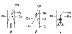
図3は図1における仕切部を図1と直交する平面でみた断面図である。
図3Aはインフレータ20の作動当初において、下部気室12内の圧力が上部気室14内のそれよりも高い状態を示しており、この状態では下部気室12側の圧力により仕切面は外側に膨張しようとする力が作用するから、仕切部40の通気孔40eが開き、下部気室12から上部気室14に向かってガスが流入する。
【0020】
図3Bは上部気室14と下部気室12の圧力が平衡した状態を示し、この状態では、仕切壁の内外面の圧力は釣り合っているため通気孔40eを通ってガスが移動することはない。例えばインフレータ20が作動していないときはこの状態である。
【0021】
図3Cは下部気室内の圧力が最高圧に達した後、その圧力が急激に低下して上部気室内の圧力が下部気室内の圧力よりも高くなった状態を示している。この状態では、上部室内14側の圧力により仕切部40の仕切面は外側から圧力を受け仕切面同士が密着し、従って、仕切部40の通気孔40eは閉塞され両気室12,14は遮断される。つまり、仕切部40は逆止弁として働く。
なお、40dはテザーであって、仕切部40の前に折り返した上縁部分をエアバッグ10を構成する一方の基布に結合している。このテザー40dは上部気室の圧力が下部気室の圧力よりも高くなったときにその反転を防止するためのものである。折り返し部以外の部分が全てエアバッグの基布に縫着されている本実施形態では省略することもできる。
【0022】
次に本実施形態係る側面衝突用エアバッグ装置1の動作について説明する。
本実施形態の側面衝突用エアバッグ装置1は、例えば車両のシートのクッション材等適宜の位置に収納されており、車両の側面に衝突による衝撃が加わると、これを衝撃センサ(図示せず)が検知して、インフレータに対してエアバッグを展開させるための起爆信号を送る。インフレータは起爆信号に応じてガスを噴出する。
【0023】
ここで、インフレータ20から噴出したガスは、ディフューザ30によって整流されて下部気室12内に噴出して下部気室12を膨張させると共にその一部は上部気室14の管状気室14aに向かい、その中に設けた仕切部40の前記通気孔40eを通して上部気室14内に導入される。
【0024】
このように、インフレータ20が作動すると上部気室と下部気室が膨張する。ここで、下部気室12のインフレータ20と反対側端部近傍には排気口16が設けられており、インフレータ20からのガスの噴流はその部分16から外部に流出して下部気室12内の圧力を効果的に要員の腰部を保護できるように調整している。これは側面からの衝突が発生した場合に、インフレータ20からのガスの噴射による下部気室内の圧力を急激に低下させて腰に対する反発力を急速に緩和して腰を保護するためである。
【0025】
他方、上部気室14側では、インフレータ20の作動当初は下部気室内の圧力は上部気室内の圧力よりも高いため、またディフューザによりガスが流れ込むため、図3Bに示すようにインフレータ20のガスの噴流の一部が前記仕切部40の通気孔40eを通して上部気室14内に導入され、上部気室14は膨張する。
上部室内14に導入されたガスは上部気室14の管状気室14aに沿って先ず上に向かって流れ、続いて前方から下方に向かって流れる。そのため上部気室14は、まず下部気室12に接する部分から乗員の腕に沿ってさらに肩から側頭部に沿って順に膨張する。つまり側面衝突が発生すると先ず乗員の腰の部分を保護し、続いて腕に沿って肩さらに側頭部と順にその保護領域を拡大していくから、乗員の腰、腕、頭の順に固定して最も安全に保護することができる。
【0026】
その間、仕切部は上部気室14内に導入された圧力が外側から作用すると共に、内側からは下部気室12側からのガス圧が作用しており、既に述べたように、下部室内側の圧力が室外側の圧力よりも高い状態が続く限り、或いはインフレータ20からのガスがディフューザで整流されて流入する限りガスは下部気室12側から上部気室14側に流入し続ける。
【0027】
この状態において、下部気室12内のガス圧が降下し、インフレータ20からのガス流が流れ込まなくなると、仕切部の内外に作用するガス圧の関係が逆転する、つまり仕切部の外側つまり上部気室内側から作用する圧力が仕切部の内側面に作用する圧力つまり下部気室12内の圧力よりも相対的に高くなるため、仕切部は内部が潰れ両側壁が密着し、前記通気孔40eは閉塞される(図3C参照)。
その結果、上部気室14内の圧力はほぼ所定の最高値に維持され、そのため腰部よりも軽く、従って長時間固定状態に保持する必要がある頭部を十分に保護することができる。
【0028】
図4は、本発明の別の実施形態を示す図1と同様の図である。
図1に示した側面衝突用エアバッグ装置との違いは、仕切部40’がディフューザ30’とを一体に形成し、それによって部品点数を一層減少するようにしかつ、下部気室12’に通気孔40e’よりも小さい通気孔30b’がディフューザ30’の下部気室12’側に形成されていることである。その他の構成は図1に示したものと同様であり、同様の部分には「’」を付した同様の番号を付与している。
なお、実際の製作に当たっては、仕切部40’とディフューザ30’を一体に作成するとエアバッグ装置の袋体の表裏両面に縫いつけることが不可能であるので、本実施形態ではディフューザ30’の上端部30’aを仕切部40’中に嵌合して一体化した構成を採っているが、本発明は、縫いつけ以外の固着手段、例えば接着等を用いることにより、エアバック装置の袋体の表裏両面に一体のまま取り付けることも包合している。
【0029】
以上、本発明を側面衝突用エアバッグ装置を例に採って説明したが、必ずしもそれに限定するものではなく、また、気室を上部気室と下部気室とからなるものとして説明したが、気室は必ずしも上部と下部気室でなくとも、例えば前後の気室であってもよい。
また、以上の実施形態では仕切部を上部気室14、14’を区画する管状の気室14a、14a’内に設けたが、管状の気室14a、14a’を設けずにエアバッグを形成する表側及び裏側の基布全体を仕切部40、40’で仕切ることも可能である。
更に、本発明の第2の気室は必ずしも1つに限るものではなく必要に応じて複数として、各気室間に前記仕切部を設けることもできる。
【0030】
【発明の効果】
請求項1に対応する効果:異なる内圧を持ったエアバッグを実現でき、身体の保護特性に応じた設定をすることができるとともに仕切部及び仕切部の通気孔閉塞手段を基布で構成するため、その作成が容易でかつ安価なエアバッグ装置を提供することができる。
請求項2に対応する効果:ディフューザを設けたことにより、エアバッグの展開初期に上部気室にガスを効率よく流出するので、上部気室の展開を早めることができる。
請求項3に対応する効果:仕切部がディフューザに連続して一体的に構成されているため構成パーツが少なくエアバッグ装置の作成をより容易に行うことができる。また、第2の通気孔の大きさで第1の気室と第2気室へのガス流量を調整することができる。
請求項4に対応する効果:比較的保護範囲が特定し易い腰部に対する保護部である第1の気室を必要最小限にし、保護範囲の特定が困難な第2の気室を大きくして乗員を確実に保護することができる。
請求項5に対応する効果:腰部の圧力を急激に低下させることで腰部に対するエアバッグの反発力を弱め、腰部に不測のダメージを与えることが防止できる。
請求項6に対応する効果:側面衝突時腕を下側から拘束することで腕がエアバッグから外れる危険性を無くし、最後に腕を固定した状態で頭部を保護するから、衝突時の安全性を一層向上させることができる。
【図面の簡単な説明】
【図1】本発明のエアバッグ装置の1実施形態の全体構成を説明するため概略断面図である。
【図2】図1の仕切部の拡大図である。
【図3】図1の平面と直交する平面における図1の仕切部の断面図であり、図3Aは上部気室と下部気室のガス圧が平衡した状態を、図3Bは下部気室内の圧力が上部気室内のそれよりも高い状態を、更に図3Cは上部気室内の圧力が下部気室内の圧力よりも高い状態を示す。
【図4】本発明のエアバッグ装置の別の実施形態の全体構成を説明するため概略断面図である。
【符号の説明】
1、1’…エアバッグ装置、10、10’…エアバッグ、10a,10a’、10b、10b’…基布、12、12’…下部気室、14、14’…上部気室、14a、14a’…管状の気室、16、16’…排気口、20、20’…インフレータ、30、30’…ディフューザ、30b’…通気孔、40、40’…仕切部、40e、40e’…通気孔。[0001]
BACKGROUND OF THE INVENTION
The present invention relates to an airbag device, and more particularly to a base fabric having a ventilation hole for a first air chamber provided with an inflator and a second air chamber for introducing gas of the inflator from the first air chamber. The present invention relates to an airbag device that is partitioned by a partition portion so that the first air chamber and the second air chamber have different pressures when deployed and inflated.
[0002]
[Prior art]
An airbag device, for example, an airbag device for side collision countermeasures, in the past used to inflate an entire airbag at a time. It is known that at the time of a collision, a waist part of an occupant sitting on a seat first hits the door and receives an impact, and then a chest part collides with the door. In this structure, since the entire structure is uniformly expanded, it is not suitable for protecting only the waist portion first, and it is not sufficient as a side collision countermeasure.
[0003]
Therefore, the airbag of the side collision airbag device is integrally configured to have two air chambers, a lower airbag corresponding to the occupant side waist and an upper airbag corresponding to the occupant side chest. There is known a system in which a pressure control valve is provided in a partition wall between an upper airbag and a lower airbag so that the lower airbag is inflated before the upper airbag (see Patent Document 1).
In this side collision airbag device, the side collision airbag deployed from the side of the seat cushion is first inflated to the height of the occupant's waist to protect the occupant's waist and then to the height of the chest. Expand.
[0004]
However, when using side impact airbags, considering not only the waist and chest but also the head, for example, the waist should reach a peak pressure by 4 ms after deployment of the side impact airbag, and then quickly depressurize. Thus, while it is necessary to weaken the repulsive force of the side collision airbag applied to the waist, the head needs to keep the peak value and be firmly fixed even if it exceeds 12 ms. Therefore, in actuality, it is necessary not only to inflate the side collision airbag but also to differentiate the pressure after inflation according to the body part. Cannot make a difference in pressure.
Therefore, in this configuration, there is a problem that the pressure cannot be adjusted to an optimum value according to the body part after the side collision airbag is inflated.
[0005]
Therefore, a partition wall provided with a communication portion is provided inside the bag body of the airbag device, and the bag body is vertically divided into first and second chambers, and both edges of the thin film are formed on the upper surface of the partition wall so as to cover the communication portion. When the gas in the lower chamber flows into the upper chamber, the intermediate portion of the check valve is caused by the pressure of the gas flowing into the upper chamber from the lower chamber through the communicating portion. The check valve is bulged upward and the check valve is released, and the gas in the lower chamber flows into the upper chamber. However, when the gas outflow pressure from the upper chamber to the lower chamber is applied, the check valve communicates with the intermediate portion of the check valve. An airbag device has been proposed in which a portion is closed to prevent gas from flowing out from the upper chamber to the lower chamber (see Patent Document 2).
However, in this air bag device, a check valve must be separately prepared and fixed to the partition wall from a plane that can be attached to it, and the number of parts increases. There are problems such as being unable to secure.
[0006]
[Patent Document 1]
Japanese Patent No. 2933894 (paragraph number “0022”)
[Patent Document 2]
Japanese Patent Laid-Open No. 10-10087 (paragraph numbers “0021” and “0022” and FIG. 1)
[0007]
[Problems to be solved by the invention]
The present invention has been made to solve the above problems in the conventional airbag device,
The first object is to effectively protect an occupant by giving a pressure difference to a plurality of air chambers with a simple configuration in an air bag including a plurality of air chambers that require different characteristics.
The second purpose is to prevent backflow from the second air chamber to the first air chamber by using a base cloth without using a part such as a pressure regulating valve separately prepared as in the prior art. Thus, the cost of the airbag apparatus is reduced.
The third object is to provide a flow path for the inflation gas of the airbag so that the occupant's body can be efficiently protected during a collision.
[0008]
[Means for Solving the Problems]
The invention of
According to a second aspect of the present invention, a diffuser for rectifying the gas flow by the inflator in the direction of the partition is provided in the first air chamber, and the diffuser has a second air flow than the first air chamber. The airbag device according to
According to a third aspect of the present invention, the partition is configured integrally with the diffuser continuously, and is smaller than the vent of the partition to supply gas to the first air chamber to the diffuser. 2. The airbag device according to
The invention according to claim 4 is the airbag device according to any one of
A fifth aspect of the present invention is the airbag apparatus according to any one of the first to fourth aspects, wherein an exhaust port is provided in the first air chamber.
According to a sixth aspect of the present invention, the base fabric on the front and back sides of the airbag guides the gas flow that has flowed into the second air chamber from the rear side of the airbag to the top, and further from the top to the front. An airbag device comprising the configuration of an airbag device according to any one of
[0009]
[Action]
According to the present invention, the second air chamber has the same peak pressure as that of the first air chamber due to the gas introduced from the first air chamber into the second air chamber through the vent hole of the partition portion, or the rectification of the diffuser. To expand to a higher pressure. After that, even if the pressure in the first air chamber decreases, the gas once introduced into the second air chamber by the check function of the partition portion does not return to the first air chamber on the inflator side. An airbag device having a chamber can be realized.
[0010]
In an emergency, when the second air chamber is expanded by the gas passing through the vent hole from the first air chamber and flowing into the second air chamber, the partition receives the gas pressure from the side surface due to this gas pressure. They are in close contact with each other and try to close the vent. However, while the pressure on the first air chamber side is high or when gas flows from the diffuser, the close contact is pushed open, and gas flows into the second air chamber from the vent hole. However, when the gas pressure on the first air chamber side becomes lower than the gas pressure on the second air chamber, the side surface of the partition receives the gas pressure and comes into close contact, thereby closing the vent hole. At that time, both sides of the partitioning portion are sewn together with the base fabric on the front and back of the airbag, so that it does not reverse to the inflator side, and at least part of the folded portion is continuous with the base fabric. Gas is induced in the direction to close the pores.
[0011]
By supplying a large amount of gas from the diffuser to the second air chamber, even if the second air chamber is larger than the first air chamber, it can be deployed quickly.
[0012]
For example, in a side collision airbag, if the first air chamber is a waist protection part, the first air chamber as the waist protection part is provided with an exhaust port for pressure relief. Can be adjusted. On the other hand, in the second air chamber, when the first air chamber is decompressed, the vent hole is closed by the pressure difference, and the upper and lower air chambers are shut off. As a result, since the pressure of the second air chamber is maintained, the air chambers having different pressure characteristics can be set in the waist protection portion and the protection portions of other portions including the head.
[0013]
Since the exhaust port (vent hole) is provided in the first air chamber, the waist protection portion can be quickly decompressed, and the repulsive force caused by the airbag to the occupant can be reduced when the airbag is activated.
[0014]
In the present invention, when the airbag is sewn, the gas introduction path is provided so as to wrap around from the rear part to the upper part and the front part of the airbag at the same time. Is possible.
[0015]
DETAILED DESCRIPTION OF THE INVENTION
A side collision airbag apparatus according to an embodiment of the airbag apparatus of the present invention will be described with reference to the drawings.
FIG. 1 is a schematic cross-sectional view for explaining the overall configuration of a side collision airbag apparatus.
As shown in the figure, the
[0016]
Due to these
[0017]
In the
[0018]
FIG. 2 is an enlarged view of the
As shown in the figure, a base fabric having a predetermined width and length is folded over at this portion, and the folded
In the folded upper edge portion of the
[0019]
3 is a cross-sectional view of the partition portion in FIG. 1 as seen in a plane orthogonal to FIG.
FIG. 3A shows a state in which the pressure in the
[0020]
FIG. 3B shows a state in which the pressures of the
[0021]
FIG. 3C shows a state in which, after the pressure in the lower air chamber reaches the maximum pressure, the pressure rapidly decreases and the pressure in the upper air chamber becomes higher than the pressure in the lower air chamber. In this state, the partition surface of the
[0022]
Next, the operation of the side
The
[0023]
Here, the gas ejected from the inflator 20 is rectified by the
[0024]
Thus, when the inflator 20 operates, the upper air chamber and the lower air chamber expand. Here, an
[0025]
On the other hand, on the
The gas introduced into the
[0026]
In the meantime, the pressure introduced into the
[0027]
In this state, when the gas pressure in the
As a result, the pressure in the
[0028]
FIG. 4 is a view similar to FIG. 1 showing another embodiment of the present invention.
The difference from the side collision airbag apparatus shown in FIG. 1 is that the
In actual production, if the
[0029]
The present invention has been described by taking the side collision airbag device as an example. However, the present invention is not necessarily limited thereto, and the air chamber is described as being composed of an upper air chamber and a lower air chamber. The chambers are not necessarily upper and lower air chambers, but may be front and rear air chambers, for example.
Further, in the above embodiment, the partition portion is provided in the
Further, the number of the second air chambers of the present invention is not necessarily limited to one, and a plurality of the air chambers may be provided between the air chambers as necessary.
[0030]
【The invention's effect】
Effect corresponding to claim 1: An airbag having different internal pressures can be realized, can be set according to the protective characteristics of the body, and the partition portion and the vent hole closing means of the partition portion are configured by the base fabric Thus, an airbag device that is easy to produce and inexpensive can be provided.
The effect corresponding to claim 2: By providing the diffuser, gas efficiently flows out into the upper air chamber at the initial stage of deployment of the airbag, so that the expansion of the upper air chamber can be accelerated.
The effect corresponding to Claim 3: Since the partition part is comprised integrally continuously with the diffuser, there are few components and it can create an airbag apparatus more easily. Further, the gas flow rate to the first air chamber and the second air chamber can be adjusted by the size of the second vent hole.
The effect corresponding to claim 4: The first air chamber which is a protection part for the waist which is relatively easy to specify the protection range is minimized, and the second air chamber which is difficult to specify the protection range is enlarged and the passenger is increased. Can be reliably protected.
The effect corresponding to claim 5: By reducing the pressure of the waist part rapidly, the repulsive force of the airbag with respect to the waist part is weakened, and unexpected damage to the waist part can be prevented.
The effect corresponding to claim 6: Since the arm is removed from the airbag by restraining the arm from the lower side at the time of a side collision, and the head is protected with the arm fixed at the end, the safety at the time of the collision Property can be further improved.
[Brief description of the drawings]
FIG. 1 is a schematic cross-sectional view for explaining an overall configuration of an embodiment of an airbag apparatus according to the present invention.
FIG. 2 is an enlarged view of the partition portion of FIG.
3 is a cross-sectional view of the partition portion of FIG. 1 in a plane orthogonal to the plane of FIG. 1, FIG. 3A shows a state in which the gas pressures in the upper and lower air chambers are in equilibrium, and FIG. FIG. 3C shows a state where the pressure is higher than that in the upper air chamber, and FIG. 3C shows a state where the pressure in the upper air chamber is higher than that in the lower air chamber.
FIG. 4 is a schematic cross-sectional view for explaining the overall configuration of another embodiment of the airbag apparatus of the present invention.
[Explanation of symbols]
DESCRIPTION OF
Claims (6)
Priority Applications (6)
| Application Number | Priority Date | Filing Date | Title |
|---|---|---|---|
| JP2003024341A JP4285633B2 (en) | 2003-01-31 | 2003-01-31 | Airbag device |
| US10/543,717 US7637530B2 (en) | 2003-01-31 | 2004-01-29 | Airbag device |
| DE602004018462T DE602004018462D1 (en) | 2003-01-31 | 2004-01-29 | AIRBAG DEVICE |
| EP04706285A EP1595751B1 (en) | 2003-01-31 | 2004-01-29 | Airbag device |
| KR1020057013385A KR101144142B1 (en) | 2003-01-31 | 2004-01-29 | Airbag device |
| PCT/JP2004/000792 WO2004067333A1 (en) | 2003-01-31 | 2004-01-29 | Airbag device |
Applications Claiming Priority (1)
| Application Number | Priority Date | Filing Date | Title |
|---|---|---|---|
| JP2003024341A JP4285633B2 (en) | 2003-01-31 | 2003-01-31 | Airbag device |
Publications (3)
| Publication Number | Publication Date |
|---|---|
| JP2004262261A JP2004262261A (en) | 2004-09-24 |
| JP2004262261A5 JP2004262261A5 (en) | 2006-01-19 |
| JP4285633B2 true JP4285633B2 (en) | 2009-06-24 |
Family
ID=32820760
Family Applications (1)
| Application Number | Title | Priority Date | Filing Date |
|---|---|---|---|
| JP2003024341A Expired - Lifetime JP4285633B2 (en) | 2003-01-31 | 2003-01-31 | Airbag device |
Country Status (6)
| Country | Link |
|---|---|
| US (1) | US7637530B2 (en) |
| EP (1) | EP1595751B1 (en) |
| JP (1) | JP4285633B2 (en) |
| KR (1) | KR101144142B1 (en) |
| DE (1) | DE602004018462D1 (en) |
| WO (1) | WO2004067333A1 (en) |
Families Citing this family (76)
| Publication number | Priority date | Publication date | Assignee | Title |
|---|---|---|---|---|
| US7168733B2 (en) | 2002-12-27 | 2007-01-30 | Takata Corporation | Airbag apparatus |
| JP4789810B2 (en) * | 2004-01-23 | 2011-10-12 | タカターペトリ(ウルム)ゲーエムベーハー | Side protector |
| DE102005028702A1 (en) * | 2004-06-28 | 2006-03-16 | Mazda Motor Corp. | Airbag device |
| WO2006049101A1 (en) * | 2004-11-05 | 2006-05-11 | Autoliv Development Ab | Side air bag device and side air bag system |
| JP4822693B2 (en) * | 2004-11-16 | 2011-11-24 | タカタ株式会社 | Airbag device |
| JP4827046B2 (en) * | 2004-11-16 | 2011-11-30 | タカタ株式会社 | Airbag device |
| US7338070B2 (en) * | 2005-03-14 | 2008-03-04 | Ford Global Technologies, Llc | Multi-chambered air bag for a motor vehicle |
| US8168133B2 (en) * | 2005-05-09 | 2012-05-01 | Wisconsin Alumni Research Foundation | Device for performing a high throughput assay |
| US7497468B2 (en) * | 2005-05-12 | 2009-03-03 | Autoliv Asp, Inc. | Airbag inflation deflection module |
| JP4815945B2 (en) * | 2005-08-19 | 2011-11-16 | トヨタ自動車株式会社 | Airbag device |
| DE102006013287A1 (en) * | 2006-03-23 | 2007-09-27 | Daimlerchrysler Ag | Airbag e.g. side airbag, for use in motor vehicle, has flow channel with reverse flow safety device that allows flow of gas in passage direction, while flow of gas into blocking direction opposite to passage direction is blocked |
| JP2007314076A (en) * | 2006-05-26 | 2007-12-06 | Toyoda Gosei Co Ltd | Side airbag device |
| JP5120599B2 (en) * | 2006-06-20 | 2013-01-16 | マツダ株式会社 | Side airbag device |
| KR100757626B1 (en) * | 2006-06-23 | 2007-09-10 | 현대모비스 주식회사 | Cushion of air bag system |
| JP4245031B2 (en) * | 2006-09-28 | 2009-03-25 | トヨタ自動車株式会社 | Side airbag device for vehicle |
| DE102006049429B4 (en) * | 2006-10-16 | 2015-12-31 | Autoliv Development Ab | airbag device |
| JP5232422B2 (en) * | 2006-11-07 | 2013-07-10 | タカタ株式会社 | Side impact airbag, side impact airbag device, vehicle seat |
| DE202007007356U1 (en) * | 2007-05-22 | 2007-10-04 | Takata-Petri Ag | Airbag arrangement |
| EP2019001B1 (en) * | 2007-07-27 | 2012-06-13 | Dalphi Metal España, S.A. | Dual chamber airbag module with anti-return difuser. |
| JP4975598B2 (en) * | 2007-12-10 | 2012-07-11 | 日本プラスト株式会社 | Knee airbag device |
| KR101000260B1 (en) * | 2007-12-13 | 2010-12-10 | 현대자동차주식회사 | Structure of Airbag Cushion with Multi Chamber |
| JP5125596B2 (en) * | 2008-02-22 | 2013-01-23 | 豊田合成株式会社 | Side airbag device |
| JP5083024B2 (en) * | 2008-05-13 | 2012-11-28 | 豊田合成株式会社 | Airbag device |
| KR101430193B1 (en) | 2008-05-19 | 2014-08-18 | 현대모비스 주식회사 | Side Air Bag for vehicle |
| JP5003631B2 (en) * | 2008-08-08 | 2012-08-15 | 豊田合成株式会社 | Side airbag device |
| DE102008057376A1 (en) | 2008-11-14 | 2010-05-20 | Daimler Ag | Airbag with channel-shaped closure element |
| US7837226B2 (en) * | 2008-12-09 | 2010-11-23 | Toyoda Gosei Co., Ltd. | Airbag apparatus |
| DE102009005834A1 (en) * | 2009-01-21 | 2009-06-04 | Takata-Petri Ag | Airbag for a passenger retention system comprises an outflow element with a double layer material piece and an outflow channel formed between material layers of the material piece by punching a section of the material piece |
| DE102009005835B4 (en) * | 2009-01-21 | 2017-12-07 | TAKATA Aktiengesellschaft | Airbag arrangement for a vehicle occupant restraint system |
| JP4892572B2 (en) * | 2009-02-12 | 2012-03-07 | トヨタ自動車株式会社 | Side airbag device and method for manufacturing side airbag |
| JP5433250B2 (en) * | 2009-02-13 | 2014-03-05 | 芦森工業株式会社 | Airbag device |
| EP2431237B1 (en) | 2009-05-11 | 2014-04-30 | Toyota Jidosha Kabushiki Kaisha | Side airbag device for vehicle |
| JP5045708B2 (en) * | 2009-06-05 | 2012-10-10 | 豊田合成株式会社 | Side airbag device |
| US8596678B2 (en) * | 2009-10-05 | 2013-12-03 | Autoliv Asp, Inc. | Air bag with pressure-managed gas delivery inflatable duct |
| WO2011077510A1 (en) | 2009-12-21 | 2011-06-30 | トヨタ自動車株式会社 | Side airbag device and method of sewing side airbag |
| JP5534515B2 (en) * | 2010-06-07 | 2014-07-02 | タカタ株式会社 | Check valve for airbag and airbag device |
| JP5615097B2 (en) * | 2010-08-26 | 2014-10-29 | 日本プラスト株式会社 | Airbag device for automobile |
| US8480124B2 (en) * | 2011-01-18 | 2013-07-09 | Autoliv Asp, Inc. | Seat bolster chamber |
| CN103889791B (en) * | 2011-10-21 | 2017-04-26 | Tk控股公司 | Airbag module and method for controlling gas therein |
| DE102011122464A1 (en) * | 2011-12-24 | 2013-06-27 | Autoliv Development Ab | Airbag with two chambers and a gas flow channel, wherein a valve is disposed in the gas flow channel |
| JP5655799B2 (en) | 2012-02-08 | 2015-01-21 | 豊田合成株式会社 | Side airbag device |
| JP2013159291A (en) * | 2012-02-08 | 2013-08-19 | Toyoda Gosei Co Ltd | Airbag apparatus |
| JP2013159304A (en) * | 2012-02-08 | 2013-08-19 | Toyoda Gosei Co Ltd | Side airbag apparatus |
| JP5918621B2 (en) * | 2012-05-09 | 2016-05-18 | 芦森工業株式会社 | Side airbag device |
| JP5787097B2 (en) * | 2012-07-06 | 2015-09-30 | 豊田合成株式会社 | Airbag device |
| JP5783145B2 (en) * | 2012-08-01 | 2015-09-24 | トヨタ自動車株式会社 | Side airbag deployment method and vehicle side airbag device |
| KR101406409B1 (en) * | 2012-11-16 | 2014-06-13 | 현대자동차주식회사 | Side airbag |
| JP5803948B2 (en) * | 2013-01-23 | 2015-11-04 | トヨタ自動車株式会社 | Side airbag device for vehicle |
| JP6070217B2 (en) * | 2013-01-25 | 2017-02-01 | 豊田合成株式会社 | Side airbag device |
| JP6137459B2 (en) * | 2013-03-26 | 2017-05-31 | 三菱自動車工業株式会社 | Side airbag device |
| US9834171B2 (en) | 2013-05-08 | 2017-12-05 | GM Global Technology Operations LLC | Fender located pedestrian protection airbag |
| DE102014106051A1 (en) * | 2013-05-08 | 2014-11-13 | GM Global Technology Operations LLC (n. d. Ges. d. Staates Delaware) | Pedestrian protection airbag on the fender |
| JP6098409B2 (en) * | 2013-07-19 | 2017-03-22 | 豊田合成株式会社 | Side airbag device |
| US9862350B2 (en) * | 2013-08-12 | 2018-01-09 | Tk Holdings Inc. | Dual chambered passenger airbag |
| JP5907135B2 (en) * | 2013-09-19 | 2016-04-20 | トヨタ自動車株式会社 | Side airbag device for vehicle |
| JP6236286B2 (en) * | 2013-10-30 | 2017-11-22 | マツダ株式会社 | Side airbag device |
| US9376084B2 (en) | 2013-12-07 | 2016-06-28 | Autoliv Asp, Inc. | Multi-chamber airbags |
| DE112015000442T5 (en) | 2014-01-21 | 2016-12-01 | Tk Holdings Inc. | Passenger side airbag |
| WO2015123156A1 (en) * | 2014-02-11 | 2015-08-20 | Key Safety Systems Inc. | Airbag cushion assembly with one-way check valves |
| JP6350798B2 (en) * | 2014-03-13 | 2018-07-04 | 三菱自動車工業株式会社 | Side airbag device for vehicle |
| US9580039B2 (en) | 2014-04-22 | 2017-02-28 | Autoliv Asp, Inc. | Multi-chamber airbag with unidirectional vent |
| JP6383176B2 (en) * | 2014-05-12 | 2018-08-29 | Joyson Safety Systems Japan株式会社 | Air bag and air bag device |
| DE102014209664A1 (en) * | 2014-05-21 | 2015-11-26 | Ford Global Technologies, Llc | Side airbag device for vehicles |
| JP6229593B2 (en) * | 2014-05-28 | 2017-11-15 | 豊田合成株式会社 | Side airbag device |
| JP6601999B2 (en) * | 2014-06-03 | 2019-11-06 | Joyson Safety Systems Japan株式会社 | Airbag device |
| US9272684B1 (en) | 2014-10-10 | 2016-03-01 | Autoliv Asp, Inc. | Multi-chamber airbag with pinch valve |
| US9533652B1 (en) | 2015-07-14 | 2017-01-03 | Autoliv Asp, Inc. | One-directional valve for multi-chamber airbags |
| US9573551B1 (en) * | 2015-11-06 | 2017-02-21 | Autoliv Asp, Inc. | Side airbag cushion and method of manufacture |
| JP6583145B2 (en) * | 2016-06-03 | 2019-10-02 | 豊田合成株式会社 | Airbag device |
| US10293777B2 (en) | 2016-08-26 | 2019-05-21 | Autoliv Asp, Inc. | Multi-cushion airbag assemblies for reducing rotational velocity of an occupant's head |
| EP3626546B1 (en) * | 2017-05-19 | 2021-10-13 | Autoliv Development AB | Side air bag device |
| JP6792523B2 (en) * | 2017-07-10 | 2020-11-25 | 本田技研工業株式会社 | Airbag device |
| CN111976644B (en) * | 2019-05-21 | 2022-10-14 | 奥托立夫开发公司 | Airbag device |
| US11173866B2 (en) * | 2019-07-24 | 2021-11-16 | Ford Global Technologies, Llc | Airbag having knee chamber and upper chamber |
| US11091111B2 (en) * | 2019-10-01 | 2021-08-17 | Ford Global Technologies, Llc | Side airbag including lower lobe and upper lobe |
| DE102020123842A1 (en) | 2020-09-14 | 2022-03-17 | Joyson Safety Systems Germany Gmbh | Gas bag and gas bag arrangement for a vehicle occupant restraint system |
Family Cites Families (23)
| Publication number | Priority date | Publication date | Assignee | Title |
|---|---|---|---|---|
| JPS51118231A (en) | 1975-04-08 | 1976-10-18 | Toyota Motor Corp | Gas bag safety device |
| JP2693789B2 (en) | 1988-09-30 | 1997-12-24 | 株式会社中埜酢店 | Polysaccharide and method for producing the same |
| JPH0542001U (en) * | 1991-11-13 | 1993-06-08 | 株式会社東海理化電機製作所 | Air bag bag |
| US5586782A (en) * | 1995-06-26 | 1996-12-24 | Alliedsignal Inc. | Dual pressure side impact air bag |
| JPH09188216A (en) | 1995-12-30 | 1997-07-22 | Tsuchiya:Kk | Bag body for gas bag device |
| US5848804A (en) | 1996-05-29 | 1998-12-15 | Trw Vehicle Safety Systems Inc. | Side impact air bag module |
| JPH1081191A (en) | 1996-09-11 | 1998-03-31 | Hino Motors Ltd | Air bag |
| JPH10100827A (en) * | 1996-09-26 | 1998-04-21 | Mitsubishi Motors Corp | Air bag device |
| US5845935A (en) | 1997-03-07 | 1998-12-08 | Morton International, Inc. | Side airbag module |
| JPH11157407A (en) | 1997-11-28 | 1999-06-15 | Nippon Plast Co Ltd | Air bag |
| US6086092A (en) * | 1998-07-07 | 2000-07-11 | Trw Vehicle Safety Systems Inc. | Inflatable vehicle occupant protection device |
| US6213499B1 (en) | 1998-08-03 | 2001-04-10 | Delphi Technologies, Inc. | Side air bag system |
| US6270113B1 (en) | 1998-10-06 | 2001-08-07 | Breed Automotive Technology, Inc. | Side air bag system |
| DE19847854C2 (en) * | 1998-10-16 | 2002-06-20 | Breed Automotive Tech | Dual-chamber airbag |
| US6254121B1 (en) * | 1998-12-14 | 2001-07-03 | Breed Automotive Technology, Inc. | Chambered driver side air bag and module attachment method |
| JP3474799B2 (en) | 1999-04-13 | 2003-12-08 | 日本プラスト株式会社 | Airbag |
| DE19930155A1 (en) | 1999-06-30 | 2001-01-04 | Takata Europ Gmbh | Check valve for airbag of motor vehicle's occupant restraint system has connecting hose between first and second chamber of airbag and in which is located fabric inlay dividing connecting hose into flow passage and pressure chamber |
| DE19930157B4 (en) * | 1999-06-30 | 2012-10-31 | TAKATA Aktiengesellschaft | Airbag for a motor vehicle |
| JP3767307B2 (en) | 2000-03-02 | 2006-04-19 | トヨタ自動車株式会社 | Airbag device |
| JP4206291B2 (en) | 2002-07-08 | 2009-01-07 | 本田技研工業株式会社 | Side airbag device |
| JP2004210257A (en) * | 2002-12-18 | 2004-07-29 | Takata Corp | Head part protection air bag and head part protection air bag device |
| JP4062094B2 (en) | 2002-12-27 | 2008-03-19 | タカタ株式会社 | Airbag device |
| US7281734B2 (en) * | 2003-01-23 | 2007-10-16 | Takata Corporation | Airbag and airbag system |
-
2003
- 2003-01-31 JP JP2003024341A patent/JP4285633B2/en not_active Expired - Lifetime
-
2004
- 2004-01-29 KR KR1020057013385A patent/KR101144142B1/en active IP Right Grant
- 2004-01-29 WO PCT/JP2004/000792 patent/WO2004067333A1/en active Application Filing
- 2004-01-29 EP EP04706285A patent/EP1595751B1/en not_active Expired - Lifetime
- 2004-01-29 US US10/543,717 patent/US7637530B2/en not_active Expired - Fee Related
- 2004-01-29 DE DE602004018462T patent/DE602004018462D1/en not_active Expired - Lifetime
Also Published As
| Publication number | Publication date |
|---|---|
| KR20060029595A (en) | 2006-04-06 |
| EP1595751A4 (en) | 2006-04-05 |
| EP1595751A1 (en) | 2005-11-16 |
| WO2004067333A1 (en) | 2004-08-12 |
| KR101144142B1 (en) | 2012-05-09 |
| JP2004262261A (en) | 2004-09-24 |
| EP1595751B1 (en) | 2008-12-17 |
| US7637530B2 (en) | 2009-12-29 |
| DE602004018462D1 (en) | 2009-01-29 |
| US20060175809A1 (en) | 2006-08-10 |
Similar Documents
| Publication | Publication Date | Title |
|---|---|---|
| JP4285633B2 (en) | Airbag device | |
| JP4566629B2 (en) | Airbag device | |
| US7431329B2 (en) | Air bag device | |
| JP5083024B2 (en) | Airbag device | |
| US7347444B2 (en) | Inflatable airbag with overlapping chamber | |
| EP2263921B1 (en) | Airbag device | |
| JP2960359B2 (en) | Gas bag protector against lateral impact | |
| JP5651788B2 (en) | Seat bolster room | |
| JP4569310B2 (en) | Knee airbag device for vehicle | |
| WO1995003953A1 (en) | Air bag with inflation limiter | |
| JP4504116B2 (en) | Airbag device | |
| US9815429B2 (en) | Adaptive vent for knee airbag | |
| JP2013086708A (en) | Airbag apparatus | |
| JP2005186891A (en) | Side airbag device for vehicle | |
| JP4453966B2 (en) | Airbag device | |
| JP2010143528A (en) | Airbag device | |
| JP2009255827A (en) | Side air-bag device | |
| JP3038479U (en) | Side airbag device | |
| JP4325444B2 (en) | Side airbag device | |
| JP2019202737A (en) | Air bag | |
| JP2007055608A (en) | Occupant leg protecting device | |
| CN109263594B (en) | Passenger airbag device and vehicle | |
| JPH10287195A (en) | Air bag for side collision | |
| WO2006127653A2 (en) | Divided airbag system | |
| JP2018184124A (en) | Airbag |
Legal Events
| Date | Code | Title | Description |
|---|---|---|---|
| A521 | Written amendment |
Free format text: JAPANESE INTERMEDIATE CODE: A523 Effective date: 20051125 |
|
| A621 | Written request for application examination |
Free format text: JAPANESE INTERMEDIATE CODE: A621 Effective date: 20051125 |
|
| A131 | Notification of reasons for refusal |
Free format text: JAPANESE INTERMEDIATE CODE: A131 Effective date: 20080422 |
|
| A521 | Written amendment |
Free format text: JAPANESE INTERMEDIATE CODE: A523 Effective date: 20080619 |
|
| A131 | Notification of reasons for refusal |
Free format text: JAPANESE INTERMEDIATE CODE: A131 Effective date: 20080821 |
|
| A521 | Written amendment |
Free format text: JAPANESE INTERMEDIATE CODE: A523 Effective date: 20081002 |
|
| TRDD | Decision of grant or rejection written | ||
| A01 | Written decision to grant a patent or to grant a registration (utility model) |
Free format text: JAPANESE INTERMEDIATE CODE: A01 Effective date: 20090318 |
|
| A01 | Written decision to grant a patent or to grant a registration (utility model) |
Free format text: JAPANESE INTERMEDIATE CODE: A01 |
|
| A61 | First payment of annual fees (during grant procedure) |
Free format text: JAPANESE INTERMEDIATE CODE: A61 Effective date: 20090318 |
|
| FPAY | Renewal fee payment (event date is renewal date of database) |
Free format text: PAYMENT UNTIL: 20120403 Year of fee payment: 3 |
|
| R150 | Certificate of patent or registration of utility model |
Ref document number: 4285633 Country of ref document: JP Free format text: JAPANESE INTERMEDIATE CODE: R150 Free format text: JAPANESE INTERMEDIATE CODE: R150 |
|
| FPAY | Renewal fee payment (event date is renewal date of database) |
Free format text: PAYMENT UNTIL: 20120403 Year of fee payment: 3 |
|
| FPAY | Renewal fee payment (event date is renewal date of database) |
Free format text: PAYMENT UNTIL: 20130403 Year of fee payment: 4 |
|
| FPAY | Renewal fee payment (event date is renewal date of database) |
Free format text: PAYMENT UNTIL: 20140403 Year of fee payment: 5 |
|
| R250 | Receipt of annual fees |
Free format text: JAPANESE INTERMEDIATE CODE: R250 |
|
| R250 | Receipt of annual fees |
Free format text: JAPANESE INTERMEDIATE CODE: R250 |
|
| R250 | Receipt of annual fees |
Free format text: JAPANESE INTERMEDIATE CODE: R250 |
|
| R250 | Receipt of annual fees |
Free format text: JAPANESE INTERMEDIATE CODE: R250 |
|
| R250 | Receipt of annual fees |
Free format text: JAPANESE INTERMEDIATE CODE: R250 |
|
| S531 | Written request for registration of change of domicile |
Free format text: JAPANESE INTERMEDIATE CODE: R313531 |
|
| R350 | Written notification of registration of transfer |
Free format text: JAPANESE INTERMEDIATE CODE: R350 |
|
| R250 | Receipt of annual fees |
Free format text: JAPANESE INTERMEDIATE CODE: R250 |