JP2007055608A - Occupant leg protecting device - Google Patents
Occupant leg protecting device Download PDFInfo
- Publication number
- JP2007055608A JP2007055608A JP2006330760A JP2006330760A JP2007055608A JP 2007055608 A JP2007055608 A JP 2007055608A JP 2006330760 A JP2006330760 A JP 2006330760A JP 2006330760 A JP2006330760 A JP 2006330760A JP 2007055608 A JP2007055608 A JP 2007055608A
- Authority
- JP
- Japan
- Prior art keywords
- chamber
- airbag
- gas
- panel
- occupant
- Prior art date
- Legal status (The legal status is an assumption and is not a legal conclusion. Google has not performed a legal analysis and makes no representation as to the accuracy of the status listed.)
- Pending
Links
Images


Abstract
Description
本発明は、自動車等の衝突時に乗員の脚部が座席前方の内装パネル等に当ることから保護するためのエアバッグを備えた乗員脚部保護装置に関する。詳しくは、エアバッグ内部に複数の室が設けられている乗員脚部保護装置に関する。 The present invention relates to an occupant leg protection device including an airbag for protecting an occupant's leg from hitting an interior panel or the like in front of a seat at the time of a collision of an automobile or the like. Specifically, the present invention relates to an occupant leg protection device in which a plurality of chambers are provided inside an airbag.
自動車の衝突時に乗員の脚部の前方にエアバッグを膨張させて脚部を受け止め、乗員を保護するようにした従来の乗員脚部保護装置にあっては、実公昭47−24110号、特開平5−208646号、特開平5−208653号、特開平5−213144号に記載されるように、内部に仕切りが設けられておらず、エアバッグ内は単一の室となっていた。
自動車の座席に座っている乗員の脚部の姿勢は、膝を開けたり、脚を左右に投げ出すようにしていたりと千差万別であり、脚部位置が座席中央から離れていることが多い。このため、乗員脚部保護装置のエアバッグは、膨張開始後、速やかに車両の左右方向に広がることが好ましい。また、膨張したエアバッグに乗員の脚部が突っ込んできた場合、脚部が前方部材に当ることがないようにエアバッグによって脚部を十分に受け止めることが望まれる。 The posture of the legs of the occupants sitting in the seats of the car is quite different, such as opening the knees or throwing the legs to the left and right, and the position of the legs is often far from the center of the seat . For this reason, it is preferable that the airbag of the occupant leg protection device spreads quickly in the left-right direction of the vehicle after the start of inflation. Moreover, when a passenger | crew's leg part protrudes into the inflated airbag, it is desirable to fully receive a leg part with an airbag so that a leg part may not hit a front member.
内部が単一の室となっているエアバッグを備えた従来の乗員脚部保護装置にあっては、膨張したエアバッグの車両前後方向の大きさ(以下、これをエアバッグの厚みということがある。)が大きいため、これを十分に大きく膨張させることにより、脚部を十分に受け止めることが可能となる。ところが、内部が単一の室からなるエアバッグを左右方向にも大きく膨張させようとすると、エアバッグの膨張時の厚みが著しく大きくなり、ガス発生器としてガス発生能力の著しく大きなものが必要となる。 In a conventional occupant leg protection device including an airbag having a single interior, the size of the inflated airbag in the vehicle front-rear direction (hereinafter referred to as the thickness of the airbag). Therefore, the leg portion can be sufficiently received by expanding it sufficiently. However, if an airbag consisting of a single chamber is to be inflated greatly in the left-right direction, the thickness of the airbag when it is inflated becomes extremely large, and a gas generator with a very large gas generating capacity is required. Become.
本発明は、ガス発生能力の小さいガス発生器を用いてもエアバッグを前方部材に沿って素早く且つ広く膨張させることができる乗員脚部保護装置を提供することを目的とする。また、本発明は、膨張時の厚みが小さくても、乗員の脚部を十分に受け止めることができる乗員脚部保護装置を提供することを目的とする。 An object of the present invention is to provide an occupant leg protection device capable of inflating an airbag quickly and widely along a front member even when a gas generator having a small gas generation capacity is used. It is another object of the present invention to provide an occupant leg protection device that can sufficiently catch an occupant's leg even when the thickness during expansion is small.
本発明の乗員脚部保護装置は、座席前方部材に設けられたエアバッグと、該エアバッグを膨張させるためのガス発生器とを有する乗員脚部保護装置において、該エアバッグは、該ガス発生器からのガスが最初に導入される第1の室と、該第1の室を通ったガスが導入される第2の室とを備えており、該第1の室及び第2の室は、該エアバッグが膨張したときに該前方部材に沿うように配置されていることを特徴とする。 The occupant leg protection device of the present invention is an occupant leg protection device having an airbag provided on a seat front member and a gas generator for inflating the airbag. A first chamber into which the gas from the vessel is first introduced, and a second chamber into which the gas that has passed through the first chamber is introduced, wherein the first chamber and the second chamber are The airbag is arranged along the front member when the airbag is inflated.
かかる本発明の乗員脚部保護装置にあっては、車両衝突時にガス発生器がガス発生作動すると、ガスがまず第1の室に流入し、次いで第1の室から第2の室に流入し、第1の室及び第2の室を膨張させる。この場合、エアバッグが前方部材に沿うように展開するので、エアバッグの前方部材からの突出量が少なく、より広い面で乗員の脚部を保護することができる。本発明では、該第2の室の入口部分が挟まっている構成としてもよい。この第2の室の入口が狭まっていると、第2の室に乗員の脚部が突っ込んできたときに第2の室内のガスが第1の室外へ逆流しにくい。このため、第2の室によって脚部を十分に受け止めることができる。 In such an occupant leg protection device of the present invention, when the gas generator generates gas at the time of a vehicle collision, the gas first flows into the first chamber and then flows from the first chamber into the second chamber. The first chamber and the second chamber are expanded. In this case, since the airbag is deployed along the front member, the amount of protrusion of the airbag from the front member is small, and the occupant's legs can be protected on a wider surface. In this invention, it is good also as a structure by which the entrance part of this 2nd chamber is pinched. If the entrance of the second chamber is narrowed, it is difficult for the gas in the second chamber to flow back to the outside of the first chamber when the occupant's legs have entered the second chamber. For this reason, the leg portion can be sufficiently received by the second chamber.
この第1及び第2の室は、いずれも前方部材に沿って膨張するものであるため、エアバッグの膨張面積が大きく、乗員脚部が種々様々な位置にあっても該脚部を受け止めることが可能である。 Since both of the first and second chambers are inflated along the front member, the inflation area of the airbag is large, and even when the occupant legs are in various positions, the legs are received. Is possible.
本発明では、エアバッグは、乗員側のフロントパネルと、該前方部材側のリヤパネルとを備えており、該エアバッグ内が、該フロントパネルとリヤパネルとを結合する線状結合部によって、前記第1の室及び第2の室に区切られていることが好ましい。かかる構成とすることにより、エアバッグの膨張時の厚みを小さくし、ガス発生能力の小さいガス発生器を用いてもエアバッグを素早く膨張させることが可能となる。 In the present invention, the airbag includes a front panel on the occupant side and a rear panel on the front member side, and the inside of the airbag is formed by the linear coupling portion that couples the front panel and the rear panel. It is preferable to be divided into one chamber and a second chamber. By adopting such a configuration, it is possible to reduce the thickness of the airbag when it is inflated and quickly inflate the airbag even if a gas generator having a small gas generation capacity is used.
また、本発明では、エアバッグは、乗員側のフロントパネルと、該前方部材側のリヤパネルとを備えており、該エアバッグ内が、該フロントパネルとリヤパネルとを接続するパーティションパネルによって、前記第1の室及び第2の室に区切られていてもよい。 In the present invention, the airbag includes a front panel on the occupant side and a rear panel on the front member side, and the interior of the airbag is the partition panel connecting the front panel and the rear panel. It may be divided into one chamber and a second chamber.
このようにすれば、パーティションパネルの大きさや形状(例えば該パーティションパネルのフロントパネルとリヤパネルとの接続方向の長さ)等を変えることにより、エアバッグの膨張時の厚さや形状等をより高い自由度にて調節することが可能となる。また、フロントパネルとリヤパネルとを線状結合部により直接的に結合した場合に比べ、エアバッグ内圧が上昇したときにフロントパネル及びリヤパネルとパーティションパネルとの結合部分に加わる応力が結合部分やパーティションパネル全体に分散されるので、各パネルの材質や結合部において使用される縫製糸もしくは接着剤が比較的低強度のもので足り、コスト安である。 In this way, by changing the size and shape of the partition panel (for example, the length of the partition panel in the connecting direction between the front panel and the rear panel), the thickness and shape of the airbag when it is inflated can be freely increased. It becomes possible to adjust in degrees. In addition, compared with the case where the front panel and the rear panel are directly coupled by the linear coupling portion, the stress applied to the coupling portion between the front panel, the rear panel, and the partition panel when the airbag internal pressure rises is increased. Since it is dispersed throughout, the material of each panel and the sewing thread or adhesive used in the connecting portion need only be relatively low in strength, and the cost is low.
本発明では、第2の室は、その入口から流入したガスがそのまま直進するように延在している構成とすることにより、第2の室の膨張を速くすることができる。この場合、第2の室の入口部分に、該入口の幅を狭めるための、該第2の室の長手方向と交叉方向に延在する仕切部を設けることにより、第2の室からのガスの逆流を確実に減少させることができる。 In the present invention, the expansion of the second chamber can be accelerated by adopting a configuration in which the gas flowing from the inlet of the second chamber extends straight as it is. In this case, the gas from the second chamber is provided by providing a partition portion extending in a direction crossing the longitudinal direction of the second chamber for narrowing the width of the inlet at the inlet portion of the second chamber. It is possible to reliably reduce the backflow.
本発明では、複数の第2の室が設けられており、少なくとも一部の第2の室の大きさが他の第2の室の大きさと異なる構成としてもよい。かかる乗員脚部保護装置によると、車両のデザインやインストルメントパネルの形状、シートのレイアウト等にあわせて前方部材と脚部との間隔が小さい領域に膨張する第2の室については、その大きさを小さくして膨張時の厚みを小さくし、前方部材と脚部との間隔が大きい領域に膨張する第2の室については、その大きさを大きくして膨張時の厚みを大きくするよう構成することができる。 In the present invention, a plurality of second chambers may be provided, and the size of at least some of the second chambers may be different from the size of the other second chambers. According to such an occupant leg protection device, the size of the second chamber that expands in a region where the distance between the front member and the leg is small in accordance with the design of the vehicle, the shape of the instrument panel, the seat layout, and the like. The second chamber that expands into a region where the distance between the front member and the leg portion is large is configured to be increased to increase the thickness during expansion. be able to.
本発明では、第1の室の少なくとも一部はエアバッグの略上下方向に延在しており、複数の第2の室が略左右方向に延在している構成としてもよい。かかる乗員脚部保護装置にあっては、第1の室から複数の第2の室にガスが分配供給されるので、各第2の室が均等に膨張する。第2の室が略左右方向に延在していると、乗員の脚部が座席中央から左右に離隔していても、この脚部を第2の室によって確実に受け止めることができる。 In the present invention, at least a part of the first chamber may extend in a substantially vertical direction of the airbag, and a plurality of second chambers may extend in a substantially horizontal direction. In such an occupant leg protection device, since the gas is distributed and supplied from the first chamber to the plurality of second chambers, each second chamber expands evenly. When the second chamber extends substantially in the left-right direction, even if the occupant's legs are separated from the center of the seat to the left and right, the legs can be reliably received by the second chamber.
本発明では、第2の室を通ったガスによって膨張する第3の室を設け、この第3の室の入口を狭めた構成としてもよい。この第3の室も、入口が狭まっているため、乗員の脚部が第3の室に突っ込んできたときにガスが第2の室に逆流しにくく、脚部を第3の室で確実に受け止めることができる。この場合も、第2及び第3の室を略左右方向に延在した構成とすることにより、乗員の脚部の位置の如何にかかわらず、脚部を確実に受け止めることが可能となる。 In this invention, it is good also as a structure which provided the 3rd chamber expanded by the gas which passed through the 2nd chamber, and narrowed the entrance of this 3rd chamber. Since the entrance of the third chamber is also narrowed, it is difficult for the gas to flow back into the second chamber when the occupant's leg rushes into the third chamber. I can take it. Also in this case, the second and third chambers are configured to extend substantially in the left-right direction, so that the legs can be reliably received regardless of the position of the legs of the occupant.
本発明においては、乗員の膝頭を受け止める室に他の室よりも大きな膨張厚みを持たせ、これによって膝頭や大腿付け根付近に加わる衝撃を十分に吸収するよう構成してもよい。 In the present invention, the chamber that receives the occupant's kneecap may have a larger expansion thickness than the other chambers, thereby sufficiently absorbing the impact applied to the vicinity of the kneecap and the thigh root.
このように乗員の膝頭を受け止める室の膨張厚みを他の室より大きくするためには、乗員の膝頭の前方付近に展開する室の膨張厚みが他の室の膨張厚みよりも大きい構成とすればよい。 In this way, in order to make the expansion thickness of the chamber that catches the occupant's kneecap larger than other chambers, if the expansion thickness of the chamber that develops in the vicinity of the front of the occupant's kneecap is larger than that of the other chamber Good.
また、乗員の膝頭を受け止める室の膨張厚みを他の室より大きくするためには、第1の室の少なくとも一部はエアバッグの略上下方向に延在しており、複数の第2の室が略左右方向に延在しているよう構成された本発明の乗員脚部保護装置において、第2の室のうちの1つがエアバッグの最上部に配置されており、この最上部の第2の室の膨張厚みが他の室の膨張厚みよりも大きいものであり、該最上部の第2の室が乗員の膝頭の前方付近に展開する構成としてもよい。 Further, in order to make the expansion thickness of the chamber that receives the occupant's kneecap larger than that of the other chambers, at least a part of the first chamber extends substantially in the vertical direction of the airbag, and the plurality of second chambers In the occupant leg protection device of the present invention configured to extend substantially in the left-right direction, one of the second chambers is disposed on the top of the airbag, and the second of the top The expansion thickness of the other chamber may be larger than the expansion thickness of the other chambers, and the uppermost second chamber may be deployed in the vicinity of the front of the occupant's kneecap.
本発明の乗員脚部保護装置は、膨張時のエアバッグの厚みが小さく、ガス発生器のガス発生能力が小さくてもエアバッグが素早く膨張する。また、膨張時の厚みが小さくても脚部を十分に受け止めることができる。 According to the occupant leg protection device of the present invention, the airbag is inflated quickly even if the thickness of the airbag when inflated is small and the gas generating capacity of the gas generator is small. Moreover, even if the thickness at the time of expansion | swelling is small, a leg part can fully be received.
以下、図面を参照して実施の形態について説明する。第1図は実施の形態に係る乗員脚部保護装置を示す縦断面図、第2図は第1図のII−II線に沿う断面図、第3図(a)はエアバッグの膨張時の乗員脚部保護装置の縦断面図、第3図(b)は第3図(a)のB−B線矢視図、第3図(c)は第3図(b)のC−C線に沿う断面図である。 Hereinafter, embodiments will be described with reference to the drawings. 1 is a longitudinal sectional view showing an occupant leg protection device according to an embodiment, FIG. 2 is a sectional view taken along the line II-II in FIG. 1, and FIG. 3 is a longitudinal sectional view of the occupant leg protection device, FIG. 3 (b) is a view taken along line BB in FIG. 3 (a), and FIG. 3 (c) is a line CC in FIG. 3 (b). FIG.
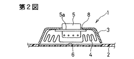
この乗員脚部保護装置1は、自動車の助手席前方の内装パネル2に設置されている。この内装パネル2はインストルメントパネルの下方に設置されている。この乗員脚部保護装置1は、助手席の座面と略々同一高さに配置されている。
The occupant leg protection device 1 is installed on an
この乗員脚部保護装置1は、内装パネル2の裏側に配置されたケース3と、折り畳まれて該ケース3内に収納されたエアバッグ4と、このエアバッグ4を膨張させるガス発生器5とを有する。ケース3は、前面が開放しており、この前面が内装パネル2によって覆われている。この内装パネル2には、エアバッグ4が膨張するときに開裂するテアライン6と、屈曲可能なヒンジライン7とが設けられている。テアライン6及びヒンジライン7は、いずれも内装パネル2に形成された凹条よりなる。
The occupant leg protection device 1 includes a
ガス発生器5は、側周から張り出すフランジ5aを備えており、エアバッグ4のガス導入口の縁部が該フランジ5aとケース3との間に挟持されている。ケース3には、ガス発生器5aを通す開口8が設けられている。フランジ5aは、この開口8の縁部にボルト9によって固定されている。図示はしないが、ケース3はブラケットを介して車体側メンバに固定されている。
The
第3図の通り、この実施の形態では、エアバッグ4は、乗員側のフロントパネル11と、裏側のリヤパネル12とからなる。リヤパネル12に、ガス発生器5の挿入孔(符号略)と、ベントホール10とが設けられている。
As shown in FIG. 3, in this embodiment, the
これらのパネル11,12の周縁部が線状に結合され、袋状となっている。符号13は、この周縁部の結合ラインを示している。
The peripheral portions of these
この周縁部の結合ライン13から複数条(この実施の形態では合計6条)の結合ライン14が延出している。各結合ライン14は、エアバッグ4が膨張した状態において略左右方向に直線状に延在した線状縫合部である。結合ライン14は、基端側が結合ライン13に連なっている。この結合ライン14によって、エアバッグ4内に合計8個の第2の室22が形成されている。
A plurality of joint lines 14 (a total of six in this embodiment) extend from the peripheral
結合ライン14の先端側からは上下方向にそれぞれ仕切部15が延出し、これにより第2の室22の入口22aが挟まっている。
From the front end side of the
第2の室22は、エアバッグ4の左側及び右側に上下方向4段に配置されている。
The
エアバッグ4の左右方向の中央に第1の室21が配置されている。該第1の室21は、エアバッグ4の上端から下端まで延在しており、その上下方向の中間の中間にガス発生器5が配置されている。
A
このように構成された乗員脚部保護装置1を備えた自動車が正面衝突すると、ガス発生器5が作動し、そのガス噴出口5bからガスが噴出し、エアバッグ4が膨張を開始する。
When the automobile equipped with the occupant leg protection device 1 configured as described above collides head-on, the
ガス発生器5からのガスは、まず第1の室21に流入し、この第1の室21が膨張を開始する。続いて、該第1の室21内のガスが入口22aを通って第2の室22を膨張させる。
The gas from the
エアバッグ4の膨張開始に伴って、内装パネル2がエアバッグ4に押圧され、テアライン6が裂け、フラップ25が形成される。このフラップ25は、ヒンジライン7に沿って屈曲する。フラップ25が開き出すのに伴ってエアバッグ4が車両室内に広がり出し、内装パネル2の前面に沿って展開する。
As the
この膨張したエアバッグ4は、突っ込んできた乗員の脚部を受け止める。脚部がエアバッグ4に突っ込んでくると、エアバッグ4内の内圧が上昇し、一部のガスがベントホール10から流出し、衝撃が吸収される。
The
この乗員脚部保護装置1にあっては、エアバッグ4内が第1の室21と第2の室22とに区画されており、まず第1の室21が膨張を開始する。この場合、殆ど全てのガス圧が第1の室21の膨張圧として作用し、第1の室21が素早く膨張する。そして、第1の室21が膨張すると、第1の室21から各第2の室22にほぼ均等にガスが分配供給されるので、各室22がほぼ均等に内装パネル2に沿って左右方向に膨張する。
In this occupant leg protection device 1, the interior of the
また、この第2の室22を区画形成する結合ライン14は直線状に延在しており、流入口22aから第2の室22内に流入したガスはそのまま直進するようになり、各第2の室22は素早く膨張する。
Further, the
このエアバッグ4のフロントパネル11とリヤパネル12とは、結合ライン14及び仕切部15によって結合されているので、エアバッグ4が最も大きく膨張した状態においても、エアバッグ4の厚みは小さい。このため、乗員脚部と内装パネル2との間の狭いスペースにおいても、乗員脚部に殆ど干渉を受けることなく素早く膨張する。膨張したエアバッグ4に脚部が突っ込んできた場合、脚部が当った室21又は22の内圧が上昇する。
Since the
この内圧上昇は、エアバッグ内の全体を単一の室とした従来例に比べて大きいので、脚部は十分に受け止められる。特に、第2の室22の入口22aが挟まっているので、第2の室22内のガスは第1の室21へ逆流しにくい。そのため、第2の室22に当った脚部は衝撃がきわめて十分に吸収される。
This increase in internal pressure is greater than in the conventional example in which the entire interior of the airbag is a single chamber, so that the legs are sufficiently received. In particular, since the
第4図〜第9図はそれぞれ別の実施の形態に係るエアバッグの正面図である。 4 to 9 are front views of airbags according to different embodiments, respectively.
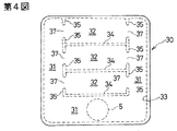
第4図のエアバッグ30は、第1の室31が下辺及び左右両辺に沿って延在したU字形状であり、ガス発生器5は下辺中央の第1の室31に配置されている。第2の室32は左右方向に延在しており、第2の室32の左右両側にそれぞれガス入口37が設けられている。33はパネル周縁の結合ライン、34は第2の室32を区画形成するための線状結合部としての結合ライン、35は入口37を狭めるための仕切部を示す。
The
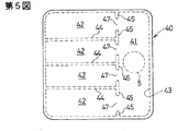
第5図のエアバッグ40は、第1の室41が右辺に沿って上下方向に配置され、第2の室42は右端側のガス入口47を介して第1の室41に連通している。ガス発生器5は、第1の室41の上下方向の中間に配置されている。43は、パネル周囲の結合ライン、44は第2の室42を区画形成するための線状結合部としての結合ライン、45はガス入口47を狭めるための仕切部を示す。
In the
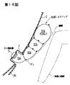
第6図のエアバッグ50は、第1の室51が左辺に沿って上下方向に配置され、第2の室52は左端側のガス入口57を介して第1の室51に連通している。ガス発生器5は、第1の室51の上部に配置されている。53は、パネル周囲の結合ライン、54は第2の室52を区画形成するための線状結合部としての結合ライン、55はガス入口57を狭めるための仕切部を示す。
In the
第7図のエアバッグ60は、上下両辺及び中央部上下に沿って第1の室61が設けられている。即ち、第1の室61は横向きH字形状となっている。この中央の第1の室61(61a)の左右両側に第2の室62が上下縦長に設けられ、この第2の室62とエアバッグ60の左右両側辺との間に第3の室63が設けられている。第2の室62はガス入口65を介して第1の室61(61a)に連通し、第3の室63はガス入口66を介して第2の室62に連通している。ガス発生器5は下辺中央の第1の室61に配置されている。
The
第8図のエアバッグ70は、中央に上下方向に第1の室71(71a)が設けられると共に、下辺に沿って第1の室71(71b)が設けられている。即ち、第1の室71は逆T字形状となっている。第2の室72は、第1の室71aの左右両側に縦長に配置され、それらの下部がガス入口74を介して第1の室71bに連通している。ガス発生器5は第1の室71aの上部に配置されている。
The
第9図の乗員脚部保護装置1’のエアバッグ80は、第1の室81、第2の室82、第3の室83及び第4の室84を備えている。第1の室81は、エアバッグ4が膨張してもその大半がケース3内に残留する。第2の室82は、この第1の室81の前方に膨張する。第3の室83は第2の室82の上方に膨張し、第4の室84は第3の室83の上方に膨張する。
The
第2,3,4の室82,83,84は、狭められたガス入口82a,83a,84aを介して第1、第2、第3の室81,82,83に連通している。
The second, third, and
第3、第4の室83,84は内装パネル2に沿って膨張する。膨張した第2,3,4の室82,83,84はそれぞれ左右方向に延在している。なお、ガス入口82a,83a,84aは1個又は複数個設けられる。
The third and
第9図のその他の構成は第3図(a)と同様である。 The other structure of FIG. 9 is the same as that of FIG. 3 (a).
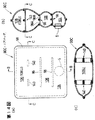
第10図(a)は本発明のさらに別の実施の形態に係るエアバッグの平面図であり、第10図(b)は第10図(a)のB−B線に沿う断面図である。 FIG. 10 (a) is a plan view of an airbag according to still another embodiment of the present invention, and FIG. 10 (b) is a sectional view taken along line BB in FIG. 10 (a). .
このエアバッグ90は、図示の通り、フロントパネル92とリヤパネル94とが3枚のパーティションパネル96によって接続されている。各パーティションパネル96は、エアバッグ90が膨張した状態において該エアバッグ90の厚さ方向及び車体左右方向に互いに略平行に延在するよう配置されている。また、第10図(a)の通り、各パーティションパネル96の左右の側縁部は、エアバッグ90の左右の側辺からそれぞれ離隔していると共に、各々上側に略J字型に曲折された曲折部96aとなっている。
In the
なお、第10図において、符号98はフロントパネル92とリヤパネル94との結合ラインを示しており、符号100は該フロントパネル92とパーティションパネル96との結合ラインを示し、符号102は該リヤパネル94とパーティションパネル96との結合ラインを示している。
In FIG. 10,
この実施の形態では、各パーティションパネル96は、一端部がフロントパネル92に結合されたパネル半体96Aと、一端部がリヤパネル94に結合されたパネル半体96Bとからなり、これらの他端部同士を縫糸108等により結合してなるものである。従って、このパーティションパネル96にあっては、これらのパネル半体96A,96Bの該他端部同士の結合代の幅を調節することにより、該パーティションパネル96の長さ(該パーティションパネル96のフロントパネル92及びリヤパネル94に対する結合端同士の間隔。即ち、結合ライン100,102間の距離。以下、同様。)が適宜調節可能となっている。
In this embodiment, each
このエアバッグ90内は、各パーティションパネル96により、該エアバッグ90の下辺及び左右の側辺に沿って略U字形に延在した第1の室104と、該エアバッグ90の上辺に沿って上下に並列に配置された3つの第2の室106とに区画されている。なお、ガス発生器5は、該エアバッグ90の下辺中央部付近の第1の室104に配置されている。
The interior of the
該ガス発生器5が作動すると、該ガス発生器5からのガスは第1の室104に流入し、殆どすべてのガス圧が該室104の膨張圧として作用し、該室104が素早く膨張する。続いて、この第1の室104内のガスは、第2の室106の各々にほぼ均等に流入し、各室106がほぼ均等に膨張する。なお、各パーティションパネル96の両端に設けられた曲折部96aによって第2の室106の入口付近が狭まっていることから、エアバッグ90の中央付近に位置する該室106に乗員脚部が突っ込んできても、該室106内に流入したガスが第1の室104に逆流しにくい。
When the
このエアバッグ90にあっては、フロントパネル92とリヤパネル94とが各パーティションパネル96によって接続されているので、エアバッグ90が最も大きく膨張した状態においても、エアバッグの厚みは小さい。しかも、このエアバッグ90にあっては、各パーティションパネル96の長さを変更することにより、このエアバッグ90の最大膨張時の厚さを適宜変更することが可能であり、設計上の自由度がきわめて高い。
In the
また、このようにパーティションパネル96によってフロントパネル92とリヤパネル94とが接続されていると、エアバッグ90の内圧が上昇したときに各パネル92,94とパーティションパネル96との結合部分に加わる応力が、該フロントパネル92とリヤパネル94とを縫合等により直接的に結合した場合と比べて小さいので、各パネル92,94の材質として比較的低強度のもので足りる。このため、エアバッグ90の製造コストも比較的安く済む。
Further, when the
上記第10図の実施の形態では、3枚のパーティションパネル96によりフロントパネル92とリヤパネル94とを接続しているが、1枚又は2枚、或いは4枚以上のパーティションパネルを用いてもよい。また、パーティションパネルの形状は任意であり、例えば、図示の如き面状のものに代えて帯紐状のものを用いてもよい。
In the embodiment of FIG. 10, the
また、次の第11図(a)〜(c)に示すエアバッグ90Aのように、パーティションパネルにベントホール(ガス流通用開口)を設け、このベントホールを介してエアバッグ内の隣接する室同士をガス流通可能に連通してもよい。以下に、このエアバッグ90Aについて詳しく説明する。なお、第11図(a)はこのエアバッグ90Aの正面図であり、第11図(b)は第11図(a)のB−B線に沿う断面図である。また、第11図(c)は、ベントホールが設けられたパーティションパネルのパネル半体を平らに広げた状態を示す斜視図である。 Further, as in the airbag 90A shown in FIGS. 11 (a) to 11 (c), a vent hole (gas distribution opening) is provided in the partition panel, and adjacent chambers in the airbag are provided through the vent hole. You may communicate each other so that gas distribution is possible. Hereinafter, the airbag 90A will be described in detail. 11 (a) is a front view of the airbag 90A, and FIG. 11 (b) is a cross-sectional view taken along the line BB in FIG. 11 (a). FIG. 11 (c) is a perspective view showing a state in which the panel half of the partition panel provided with the vent holes is flattened.
このエアバッグ90Aにおいては、第10図のエアバッグ90と同様に、該エアバッグ90Aの膨張状態において該エアバッグ90Aの厚さ方向及び左右幅方向に平行に延在し、且つ該エアバッグ90Aの上下高さ方向に並列の位置関係となるように配置された3枚のパーティションパネル96よりフロントパネル92とリヤパネル94とが接続されている。
In the airbag 90A, similarly to the
この実施の形態では、第11図(b),(c)に示すように、これら3枚のパーティションパネル96のうち一番下側に配置されたパーティションパネル96(96’)のパネル半体96B(96B’)に複数個の小孔状のベントホール112が設けられている。また、第11図(a)に示すように、この一番下側のパーティションパネル96(96’)の左右の側縁部は、それぞれ他の2枚のパーティションパネル96の左右の側縁部よりもエアバッグ90Aの左右の側辺に近い位置まで延在されており、該エアバッグ90Aの左右の側辺の近傍において曲折部96aを形成している。
In this embodiment, as shown in FIGS. 11 (b) and 11 (c), the
なお、この実施の形態では、パーティションパネル96(96’)の左右の側縁部とエアバッグ90Aの左右の側辺との間隔は、エアバッグ90Aが膨張したときには、該エアバッグ90Aの厚みが増すことに伴って該エアバッグ90Aの左右の側辺が互いに接近方向に移動することにより、殆ど塞がれた状態となる程度の規模となっているが、エアバッグ90Aが膨張しても両者の間に隙間が介在される大きさとしてもよい。 In this embodiment, the distance between the left and right side edges of the partition panel 96 (96 ′) and the left and right sides of the airbag 90A is such that when the airbag 90A is inflated, the thickness of the airbag 90A is As the airbag 90A increases, the left and right sides of the airbag 90A move toward each other so that the airbag 90A is almost closed. The size may be such that a gap is interposed between them.
このエアバッグ90A内は、これら3枚のパーティションパネル96によって、該エアバッグ90Aの下辺に沿って左右幅方向に延在した第1の室116と、該室116の上辺及びエアバッグ90Aの左右の側辺に沿って略U字形に延在した第2の室118と、該エアバッグ90Aの上辺に沿って左右幅方向に延在し、且つ上下に並列に配置された2つの第3の室120とに区画されている。ガス発生器5は該エアバッグ90Aの下辺中央部付近の第1の室116に配置されている。
The airbag 90A includes a
このエアバッグ90Aのその他の構成は前述の第10図のエアバッグ90と同一となっており、第11図(a)〜(c)において第10図と同一の部分には同一の符号を付すことによりその説明を省略する。
The other configuration of the airbag 90A is the same as that of the
ガス発生器5が作動すると、該ガス発生器5からのガスは第1の室116に流入し、殆どすべてのガス圧が該室116の膨張圧として作用するので、該室116が素早く膨張する。続いて、この第1の室116内のガスがパーティションパネル96(96’)に設けられたベントホール112や該パーティションパネル96(96’)の両サイドを通って第2の室118に流入し、該室118が膨張する。なお、この実施の形態では、エアバッグ90Aが膨張するとパーティションパネル96(96’)の左右の側縁部と該エアバッグ90Aの左右の側辺との間の間隙がほぼ塞がれるように構成されており、第1の室116内のガスは、殆どがベントホール112を通って第2の室118に流入し、ごく一部のガスのみがパーティションパネル96(96’)の両サイドを通って第2の室118に流入する。この第2の室118内のガスは引き続き第3の室120,120に流入し、各室120が膨張する。
When the
この実施の形態では、エアバッグ90Aが膨張すると、一番下側のパーティションパネル96(96’)の側縁部と該エアバッグ90Aの左右の側辺との間の間隙がほぼ塞がれた状態となり、パーティションパネル96(96’)の両サイドを通って第1の室116から第2の室118に抜け出すガス量はごく僅かなものとなる。そのため、第1の室116の左右両端側にガスが溜まり易く、該第1の室112は左右の隅々まで素早く膨張する。そのため、ベントホール112を通して比較的早期に高圧且つ高流速のガスが第2室に流入し始めるようになり、さらに、この第2の室118内のガスも早期に第3の室120に流入し始めるようになる。この結果、各室116〜120がさほど時間差なく膨張し、エアバッグ90Aが全体として極めてスムーズに膨張するようになる。
In this embodiment, when the airbag 90A is inflated, the gap between the side edge of the lowermost partition panel 96 (96 ′) and the left and right sides of the airbag 90A is almost closed. Thus, the amount of gas that escapes from the
この実施の形態では、複数のパーティションパネルのうち一番下側のパーティションパネルの一方のパネル半体にのみベントホールを設けているが、他方のパネル半体にもベントホールを設けてもよい。また、ベントホールはいずれのパーティションパネルに設けてもよく、すべてのパーティションパネルに設けてもよい。また、第11図(c)に示すように、この実施の形態では複数個の小孔状のベントホールを設けているが、ベントホールの形状や大きさ、個数などの構成はこれに限られるものではない。ベントホールの形状や大きさ、個数等をエアバッグの構成等に合わせて適宜変更・調節することにより、該エアバッグの膨張時の挙動をコントロールすることも可能である。 In this embodiment, a vent hole is provided only in one panel half of the lowermost partition panel among the plurality of partition panels, but a vent hole may also be provided in the other panel half. Further, the vent hole may be provided in any partition panel, or may be provided in all partition panels. Further, as shown in FIG. 11 (c), in this embodiment, a plurality of small hole-shaped vent holes are provided. However, the configuration of the shape, size, number, etc. of the vent holes is limited to this. It is not a thing. It is also possible to control the behavior of the airbag when it is inflated by appropriately changing and adjusting the shape, size, number, etc. of the vent holes according to the configuration of the airbag.
第12図〜第15図を参照して、膝頭を受け止める室の膨張厚みを他の室の膨張厚みよりも大きくした実施の形態について説明する。 With reference to FIGS. 12 to 15, an embodiment in which the expansion thickness of the chamber for receiving the kneecap is made larger than the expansion thickness of the other chambers will be described.
第12図及び第13図は、かかるエアバッグの第1の例を示しており、第12図(a)はエアバッグの正面図、第12図(b)は第12図(a)のB−B線に沿う断面図、第13図は、このエアバッグが内装パネルに沿って膨張展開した状態を示す縦断面図である。 FIGS. 12 and 13 show a first example of such an airbag. FIG. 12 (a) is a front view of the airbag, and FIG. 12 (b) is B in FIG. 12 (a). FIG. 13 is a longitudinal sectional view showing a state where the airbag is inflated and deployed along the interior panel.
このエアバッグ90Bは、前記第10図に示したエアバッグ90と類似した構成を有している。即ち、このエアバッグ90Bは、エアバッグ90と同様に、フロントパネル92とリヤパネル94とが3枚のパーティションパネル96によって接続されている。各パーティションパネル96は、エアバッグ90Bが膨張した状態において該エアバッグ90Bの厚さ方向及び車体左右方向に互いに略平行に延在するよう配置されている。ただし、この実施の形態では、各パーティションパネル96は一文字状に左右方向に延在している。
The
この実施の形態では、3枚のパーティションパネル96のうち最も上位のものとエアバッグ90Bの上端辺との間隔は、パーティションパネル96同士の間の間隔及びパーティションパネル96とエアバッグ90Bの最下部との間隔よりも大きなものとなっている。これにより、最上部の第2の室106(106U)は他の第2の室106及び第1の室104よりも膨張厚みが大きなものとなっている。第2の室106Uはエアバッグ90Bの最上部に位置している。
In this embodiment, the interval between the uppermost one of the three
このエアバッグ90Bのその他の構成はエアバッグ90と同一であり、同一符号は同一部分を示している。
The other structure of this
ガス発生器5が作動すると、該ガス発生器5からのガスは第1の室104に流入し、殆どすべてのガス圧が該室104の膨張圧として作用し、該室104が素早く膨張する。続いて、この第1の室104内のガスは、第2の室106の各々にほぼ均等に流入し、各室106がほぼ均等に膨張する。
When the
このエアバッグ90Bにあっては、最上位の第2の室106Uは、座席の座面の前方延長付近からそれよりも上位の領域にかけて膨張展開する。そのため、この最上位の第2の室106Uは、乗員の膝頭の前方付近に膨張展開するようになり、膝頭を受け止め、膝頭や大腿付け根付近の衝撃を十分に吸収する。
In this
この実施の形態にあっては、第16図に示すエアバッグ90B’の通り、パーティションパネルの長さや配置等を選定することにより、エアバッグの膨張時の厚みが下側から上側に向けて徐々に大きくなるように構成してもよい。なお、第16図の線FLは、エアバッグ90B’の乗員対向面の包絡線を模式的に示している。この包絡線FLと内装パネル2との間隔は、上方ほど大となっている。
In this embodiment, as the
上記第12,13図及び第16図の実施の形態では、3枚のパーティションパネル96によりフロントパネル92とリヤパネル94とを接続しているが、1枚又は2枚、或いは4枚以上のパーティションパネルを用いてもよい。
In the embodiment shown in FIGS. 12, 13 and 16, the
また、次の第14図(a)〜(c)に示すエアバッグ90Cのように、最上位の第2の室106U内に、フロントパネル92とリヤパネル94とを結ぶテザー(吊紐)140を設けてもよい。なお、第14図(a)はこのエアバッグ90Cの正面図であり、第14図(b),(c)は第14図(a)のB−B線、C−C線に沿う断面図である。
Further, like an
このテザー140を設けることにより、最上位の第2の室106Uの膨張厚みが過大となることが防止される。なお、第14図では2本のテザー140を設けているが、1本又は3本以上のテザーを設けてもよい。
By providing the
第15図(a),(b)は、前記第4図のエアバッグ30において最上位の第2の室32(32U)を他の第2の室32及び第1の室31よりも膨張厚みの大きなものとしたエアバッグ30Aを示している。なお、第15図(a)はこのエアバッグ30Aの正面図、第15図(b)は第15図(a)のB−B線に沿う断面図である。
FIGS. 15 (a) and 15 (b) show that the uppermost second chamber 32 (32U) in the
このエアバッグ30Aは、乗員側のフロントパネル11と、裏側のリヤパネル12とからなる。リヤパネル12に、ガス発生器5の挿入孔(符号略)が設けられている。
The
これらのパネル11,12の周縁部が線状に結合され、袋状となっている。符号33は、この周縁部の結合ラインを示している。
The peripheral portions of these
このエアバッグ30Aも、第4図のエアバッグ30と同様に、第1の室31が下辺及び左右両辺に沿って延在したU字形状であり、ガス発生器5は下辺中央の第1の室31に配置されている。第2の室32は左右方向に延在しており、第2の室32の左右両側にそれぞれガス入口37が設けられている。34は第2の室32を区画形成するための線状結合部としての結合ライン、35は入口37を狭めるための仕切部を示す。なお、仕切部35は省略されてもよい。
As with the
このエアバッグ30Aは、第2の室32が複数個設けられており、そのうち最上位の第2の室32はエアバッグ30Aの最上部に位置している。結合ライン34とエアバッグ30Aの最上部との間隔は、結合ライン34同士の間隔及び結合ライン34とエアバッグ30Aの最下部との間隔よりも大きなものとなっている。そのため、最上位の第2の室32Uの膨張厚みは、他の第2の室32及び第1の室31よりも大きなものとなっている。
The
この最上位の第2の室32Uは、乗員の膝頭の前方付近に膨張展開し、乗員の膝頭を受け止める。
The uppermost
この実施の形態においても、第17図のエアバッグ30Bのように、下側から室32a,32b,32cが徐々に大径になり、エアバッグの乗員対向面の包絡線FLが上方ほど内装パネル2との間隔が大となる構成としてもよい。
Also in this embodiment, as in the airbag 30B in FIG. 17, the
上記の各実施の形態では、乗員脚部保護装置が内装パネル2に設けられているが、グローブボックスに設けられてもよい。結合ラインは糸による縫合だけでなく接着剤を用いた結合や、接着剤と糸による縫合の両方を用いた結合でもよい。
In each of the above embodiments, the occupant leg protection device is provided in the
1,1’ 乗員脚部保護装置
2 内装パネル
3 ケース
4 エアバッグ
5 ガス発生器
6 テアライン
7 ヒンジライン
10 ベントホール
11 フロントパネル
12 リヤパネル
21 第1の室
22 第2の室
22a ガス入口
25 フラップ
30,30A,30B,40,50,60,70,80,90,90A,90B,90B’,90C エアバッグ
31,41,51,61,71,81,104,116 第1の室
32,32a,32b,32c,42,52,62,72,82,106,118 第2の室
63,83,120 第3の室
84 第4の室
92 フロントパネル
94 リヤパネル
96 パーティションパネル
112 ベントホール
140 テザー
1, 1 'Crew
Claims (11)
該エアバッグを膨張させるためのガス発生器と
を有する乗員脚部保護装置において、
該エアバッグは、該ガス発生器からのガスが最初に導入される第1の室と、該第1の室を通ったガスが導入される第2の室とを備えており、
該第1の室及び第2の室は、該エアバッグが膨張したときに該前方部材に沿うように配置されていることを特徴とする乗員脚部保護装置。 An airbag provided in the seat front member;
In an occupant leg protection device having a gas generator for inflating the airbag,
The airbag includes a first chamber into which gas from the gas generator is first introduced, and a second chamber into which gas that has passed through the first chamber is introduced,
The occupant leg protection device according to claim 1, wherein the first chamber and the second chamber are disposed along the front member when the airbag is inflated.
該エアバッグ内が、該フロントパネルとリヤパネルとを結合する線状結合部によって、前記第1の室及び第2の室に区切られていることを特徴とする乗員脚部保護装置。 In Claim 1 or 2, the airbag includes a front panel on the passenger side and a rear panel on the front member side,
The occupant leg protection device according to claim 1, wherein the airbag is partitioned into the first chamber and the second chamber by a linear coupling portion that couples the front panel and the rear panel.
該エアバッグ内が、該フロントパネルとリヤパネルとを接続するパーティションパネルによって、前記第1の室及び第2の室に区切られていることを特徴とする乗員脚部保護装置。 In Claim 1 or 2, the airbag includes a front panel on the passenger side and a rear panel on the front member side,
An occupant leg protection device, wherein the airbag is partitioned into the first chamber and the second chamber by a partition panel connecting the front panel and the rear panel.
該第2の室の入口部分には、該入口の幅を狭めるための、該第2の室の長手方向と交叉方向に延在する仕切部が設けられていることを特徴とする乗員脚部保護装置。 In any one of Claims 1 thru | or 4, this 2nd chamber is extended so that the gas which flowed in from the inlet may go straight as it is,
An occupant leg portion characterized in that a partition portion extending in a longitudinal direction and a crossing direction of the second chamber is provided at an entrance portion of the second chamber to narrow the width of the entrance. Protective device.
少なくとも一部の第2の室の大きさが他の第2の室の大きさと異なることを特徴とする乗員脚部保護装置。 In any one of Claims 1 thru | or 5, The several 2nd chamber is provided,
An occupant leg protecting device, wherein the size of at least some of the second chambers is different from the size of the other second chambers.
該最上部の第2の室が乗員の膝頭の前方付近に展開することを特徴とする乗員脚部保護装置。 In claim 7, one of the second chambers is disposed at the uppermost portion of the airbag, and the inflated thickness of the uppermost second chamber is larger than the inflated thickness of the other chambers,
The occupant leg protection device, wherein the uppermost second chamber is deployed in the vicinity of the front of the occupant's kneecap.
Priority Applications (1)
| Application Number | Priority Date | Filing Date | Title |
|---|---|---|---|
| JP2006330760A JP2007055608A (en) | 2001-05-21 | 2006-12-07 | Occupant leg protecting device |
Applications Claiming Priority (4)
| Application Number | Priority Date | Filing Date | Title |
|---|---|---|---|
| JP2001151165 | 2001-05-21 | ||
| JP2001320680 | 2001-10-18 | ||
| JP2001359689 | 2001-11-26 | ||
| JP2006330760A JP2007055608A (en) | 2001-05-21 | 2006-12-07 | Occupant leg protecting device |
Related Parent Applications (1)
| Application Number | Title | Priority Date | Filing Date |
|---|---|---|---|
| JP2002063991A Division JP3912144B2 (en) | 2001-05-21 | 2002-03-08 | Passenger leg protection device for passenger seat |
Publications (2)
| Publication Number | Publication Date |
|---|---|
| JP2007055608A true JP2007055608A (en) | 2007-03-08 |
| JP2007055608A5 JP2007055608A5 (en) | 2008-05-22 |
Family
ID=37919423
Family Applications (1)
| Application Number | Title | Priority Date | Filing Date |
|---|---|---|---|
| JP2006330760A Pending JP2007055608A (en) | 2001-05-21 | 2006-12-07 | Occupant leg protecting device |
Country Status (1)
| Country | Link |
|---|---|
| JP (1) | JP2007055608A (en) |
Cited By (4)
| Publication number | Priority date | Publication date | Assignee | Title |
|---|---|---|---|---|
| JP2009083549A (en) * | 2007-09-27 | 2009-04-23 | Toyoda Gosei Co Ltd | Knee protective airbag |
| JP2010149688A (en) * | 2008-12-25 | 2010-07-08 | Toyoda Gosei Co Ltd | Airbag |
| WO2016027543A1 (en) * | 2014-08-20 | 2016-02-25 | タカタ株式会社 | Device for restraining automobile occupant's legs, and airbag for device for restraining automobile occupant's legs |
| GB2546357A (en) * | 2015-11-02 | 2017-07-19 | Ford Global Tech Llc | Dual chamber airbag with asymmetrically tunable parameters and method of manufacturing the same |
-
2006
- 2006-12-07 JP JP2006330760A patent/JP2007055608A/en active Pending
Cited By (8)
| Publication number | Priority date | Publication date | Assignee | Title |
|---|---|---|---|---|
| JP2009083549A (en) * | 2007-09-27 | 2009-04-23 | Toyoda Gosei Co Ltd | Knee protective airbag |
| JP4530018B2 (en) * | 2007-09-27 | 2010-08-25 | 豊田合成株式会社 | Knee protection airbag |
| JP2010149688A (en) * | 2008-12-25 | 2010-07-08 | Toyoda Gosei Co Ltd | Airbag |
| WO2016027543A1 (en) * | 2014-08-20 | 2016-02-25 | タカタ株式会社 | Device for restraining automobile occupant's legs, and airbag for device for restraining automobile occupant's legs |
| US10351091B2 (en) | 2014-08-20 | 2019-07-16 | Takata Corporation | Occupant's leg restraint device and airbag for occupant's leg restraint device |
| GB2546357A (en) * | 2015-11-02 | 2017-07-19 | Ford Global Tech Llc | Dual chamber airbag with asymmetrically tunable parameters and method of manufacturing the same |
| US9789844B2 (en) | 2015-11-02 | 2017-10-17 | Ford Global Technologies, Llc | Dual chamber airbag with asymmetrically tunable parameters and method of manufacturing the same |
| US10300882B2 (en) | 2015-11-02 | 2019-05-28 | Ford Global Technologies, Llc | Dual chamber airbag with asymmetrically tunable parameters and method of manufacturing the same |
Similar Documents
| Publication | Publication Date | Title |
|---|---|---|
| JP3912144B2 (en) | Passenger leg protection device for passenger seat | |
| JP3948332B2 (en) | Crew protection device | |
| US7380823B2 (en) | Knee-bag and occupant leg protection apparatus | |
| JP4285633B2 (en) | Airbag device | |
| US6669229B2 (en) | Automotive vehicle air bag system | |
| US8302991B2 (en) | Knee airbag and method of folding the same | |
| US10457243B2 (en) | Knee airbag assemblies | |
| US10618494B2 (en) | Airbag assemblies with anchored positional tether | |
| US20050134024A1 (en) | Kneebag and occupant leg protection system | |
| JP2002053000A (en) | Air bag | |
| JP4569310B2 (en) | Knee airbag device for vehicle | |
| JP2005186891A (en) | Side airbag device for vehicle | |
| JP5187818B2 (en) | Air bag device for knee protection | |
| JP4453966B2 (en) | Airbag device | |
| JP2007055608A (en) | Occupant leg protecting device | |
| JP3991720B2 (en) | Crew protection device | |
| JP2007055608A5 (en) | ||
| JP6864715B2 (en) | Knee airbag device for vehicles | |
| JP5520500B2 (en) | Knee airbag device | |
| JP2009023493A (en) | Airbag device | |
| JP6631434B2 (en) | Far side airbag device | |
| KR101758809B1 (en) | Knee airbag apparatus | |
| JP3463993B2 (en) | Airbag device for side collision | |
| JP2019077225A (en) | Air bag device |
Legal Events
| Date | Code | Title | Description |
|---|---|---|---|
| A621 | Written request for application examination |
Free format text: JAPANESE INTERMEDIATE CODE: A621 Effective date: 20061207 |
|
| A521 | Written amendment |
Free format text: JAPANESE INTERMEDIATE CODE: A523 Effective date: 20080403 |
|
| A977 | Report on retrieval |
Free format text: JAPANESE INTERMEDIATE CODE: A971007 Effective date: 20090225 |
|
| A131 | Notification of reasons for refusal |
Free format text: JAPANESE INTERMEDIATE CODE: A131 Effective date: 20090303 |
|
| A521 | Written amendment |
Free format text: JAPANESE INTERMEDIATE CODE: A523 Effective date: 20090428 |
|
| A02 | Decision of refusal |
Free format text: JAPANESE INTERMEDIATE CODE: A02 Effective date: 20090804 |