EP2430889B1 - Method, treatment station, and system for the treatment of flat feedstock - Google Patents
Method, treatment station, and system for the treatment of flat feedstock Download PDFInfo
- Publication number
- EP2430889B1 EP2430889B1 EP10721984.2A EP10721984A EP2430889B1 EP 2430889 B1 EP2430889 B1 EP 2430889B1 EP 10721984 A EP10721984 A EP 10721984A EP 2430889 B1 EP2430889 B1 EP 2430889B1
- Authority
- EP
- European Patent Office
- Prior art keywords
- treated
- roller
- treatment
- transport
- gap
- Prior art date
- Legal status (The legal status is an assumption and is not a legal conclusion. Google has not performed a legal analysis and makes no representation as to the accuracy of the status listed.)
- Active
Links
- 0 CC(C1C*C1)N=O Chemical compound CC(C1C*C1)N=O 0.000 description 1
Images


Classifications
-
- H—ELECTRICITY
- H05—ELECTRIC TECHNIQUES NOT OTHERWISE PROVIDED FOR
- H05K—PRINTED CIRCUITS; CASINGS OR CONSTRUCTIONAL DETAILS OF ELECTRIC APPARATUS; MANUFACTURE OF ASSEMBLAGES OF ELECTRICAL COMPONENTS
- H05K3/00—Apparatus or processes for manufacturing printed circuits
- H05K3/38—Improvement of the adhesion between the insulating substrate and the metal
-
- H—ELECTRICITY
- H05—ELECTRIC TECHNIQUES NOT OTHERWISE PROVIDED FOR
- H05K—PRINTED CIRCUITS; CASINGS OR CONSTRUCTIONAL DETAILS OF ELECTRIC APPARATUS; MANUFACTURE OF ASSEMBLAGES OF ELECTRICAL COMPONENTS
- H05K3/00—Apparatus or processes for manufacturing printed circuits
- H05K3/0085—Apparatus for treatments of printed circuits with liquids not provided for in groups H05K3/02 - H05K3/46; conveyors and holding means therefor
-
- B—PERFORMING OPERATIONS; TRANSPORTING
- B05—SPRAYING OR ATOMISING IN GENERAL; APPLYING FLUENT MATERIALS TO SURFACES, IN GENERAL
- B05C—APPARATUS FOR APPLYING FLUENT MATERIALS TO SURFACES, IN GENERAL
- B05C11/00—Component parts, details or accessories not specifically provided for in groups B05C1/00 - B05C9/00
- B05C11/02—Apparatus for spreading or distributing liquids or other fluent materials already applied to a surface ; Controlling means therefor; Control of the thickness of a coating by spreading or distributing liquids or other fluent materials already applied to the coated surface
- B05C11/06—Apparatus for spreading or distributing liquids or other fluent materials already applied to a surface ; Controlling means therefor; Control of the thickness of a coating by spreading or distributing liquids or other fluent materials already applied to the coated surface with a blast of gas or vapour
-
- B—PERFORMING OPERATIONS; TRANSPORTING
- B05—SPRAYING OR ATOMISING IN GENERAL; APPLYING FLUENT MATERIALS TO SURFACES, IN GENERAL
- B05C—APPARATUS FOR APPLYING FLUENT MATERIALS TO SURFACES, IN GENERAL
- B05C3/00—Apparatus in which the work is brought into contact with a bulk quantity of liquid or other fluent material
- B05C3/02—Apparatus in which the work is brought into contact with a bulk quantity of liquid or other fluent material the work being immersed in the liquid or other fluent material
- B05C3/09—Apparatus in which the work is brought into contact with a bulk quantity of liquid or other fluent material the work being immersed in the liquid or other fluent material for treating separate articles
-
- B—PERFORMING OPERATIONS; TRANSPORTING
- B32—LAYERED PRODUCTS
- B32B—LAYERED PRODUCTS, i.e. PRODUCTS BUILT-UP OF STRATA OF FLAT OR NON-FLAT, e.g. CELLULAR OR HONEYCOMB, FORM
- B32B15/00—Layered products comprising a layer of metal
- B32B15/04—Layered products comprising a layer of metal comprising metal as the main or only constituent of a layer, which is next to another layer of the same or of a different material
- B32B15/08—Layered products comprising a layer of metal comprising metal as the main or only constituent of a layer, which is next to another layer of the same or of a different material of synthetic resin
-
- C—CHEMISTRY; METALLURGY
- C25—ELECTROLYTIC OR ELECTROPHORETIC PROCESSES; APPARATUS THEREFOR
- C25D—PROCESSES FOR THE ELECTROLYTIC OR ELECTROPHORETIC PRODUCTION OF COATINGS; ELECTROFORMING; APPARATUS THEREFOR
- C25D17/00—Constructional parts, or assemblies thereof, of cells for electrolytic coating
-
- C—CHEMISTRY; METALLURGY
- C25—ELECTROLYTIC OR ELECTROPHORETIC PROCESSES; APPARATUS THEREFOR
- C25D—PROCESSES FOR THE ELECTROLYTIC OR ELECTROPHORETIC PRODUCTION OF COATINGS; ELECTROFORMING; APPARATUS THEREFOR
- C25D21/00—Processes for servicing or operating cells for electrolytic coating
- C25D21/10—Agitating of electrolytes; Moving of racks
-
- C—CHEMISTRY; METALLURGY
- C25—ELECTROLYTIC OR ELECTROPHORETIC PROCESSES; APPARATUS THEREFOR
- C25D—PROCESSES FOR THE ELECTROLYTIC OR ELECTROPHORETIC PRODUCTION OF COATINGS; ELECTROFORMING; APPARATUS THEREFOR
- C25D7/00—Electroplating characterised by the article coated
- C25D7/06—Wires; Strips; Foils
- C25D7/0614—Strips or foils
- C25D7/0621—In horizontal cells
-
- C—CHEMISTRY; METALLURGY
- C25—ELECTROLYTIC OR ELECTROPHORETIC PROCESSES; APPARATUS THEREFOR
- C25D—PROCESSES FOR THE ELECTROLYTIC OR ELECTROPHORETIC PRODUCTION OF COATINGS; ELECTROFORMING; APPARATUS THEREFOR
- C25D7/00—Electroplating characterised by the article coated
- C25D7/06—Wires; Strips; Foils
- C25D7/0614—Strips or foils
- C25D7/0642—Anodes
-
- H—ELECTRICITY
- H05—ELECTRIC TECHNIQUES NOT OTHERWISE PROVIDED FOR
- H05K—PRINTED CIRCUITS; CASINGS OR CONSTRUCTIONAL DETAILS OF ELECTRIC APPARATUS; MANUFACTURE OF ASSEMBLAGES OF ELECTRICAL COMPONENTS
- H05K2203/00—Indexing scheme relating to apparatus or processes for manufacturing printed circuits covered by H05K3/00
- H05K2203/01—Tools for processing; Objects used during processing
- H05K2203/0104—Tools for processing; Objects used during processing for patterning or coating
- H05K2203/0143—Using a roller; Specific shape thereof; Providing locally adhesive portions thereon
-
- H—ELECTRICITY
- H05—ELECTRIC TECHNIQUES NOT OTHERWISE PROVIDED FOR
- H05K—PRINTED CIRCUITS; CASINGS OR CONSTRUCTIONAL DETAILS OF ELECTRIC APPARATUS; MANUFACTURE OF ASSEMBLAGES OF ELECTRICAL COMPONENTS
- H05K2203/00—Indexing scheme relating to apparatus or processes for manufacturing printed circuits covered by H05K3/00
- H05K2203/07—Treatments involving liquids, e.g. plating, rinsing
- H05K2203/0736—Methods for applying liquids, e.g. spraying
- H05K2203/0746—Local treatment using a fluid jet, e.g. for removing or cleaning material; Providing mechanical pressure using a fluid jet
-
- H—ELECTRICITY
- H05—ELECTRIC TECHNIQUES NOT OTHERWISE PROVIDED FOR
- H05K—PRINTED CIRCUITS; CASINGS OR CONSTRUCTIONAL DETAILS OF ELECTRIC APPARATUS; MANUFACTURE OF ASSEMBLAGES OF ELECTRICAL COMPONENTS
- H05K2203/00—Indexing scheme relating to apparatus or processes for manufacturing printed circuits covered by H05K3/00
- H05K2203/15—Position of the PCB during processing
- H05K2203/1509—Horizontally held PCB
-
- H—ELECTRICITY
- H05—ELECTRIC TECHNIQUES NOT OTHERWISE PROVIDED FOR
- H05K—PRINTED CIRCUITS; CASINGS OR CONSTRUCTIONAL DETAILS OF ELECTRIC APPARATUS; MANUFACTURE OF ASSEMBLAGES OF ELECTRICAL COMPONENTS
- H05K2203/00—Indexing scheme relating to apparatus or processes for manufacturing printed circuits covered by H05K3/00
- H05K2203/15—Position of the PCB during processing
- H05K2203/1572—Processing both sides of a PCB by the same process; Providing a similar arrangement of components on both sides; Making interlayer connections from two sides
Definitions
- the invention relates to a method, a treatment station and a system for treating flat material to be treated. More particularly, the invention relates to such methods, treatment stations, and facilities that permit treatment of items to be treated having one or more sensitive surfaces. The invention also relates to such methods, treatment stations and installations in which a contact between a useful area to be treated of the material to be treated and solid elements can be reduced.
- treatment of the material to be treated often takes place in a wet-chemical process line.
- treatment liquid such as a process chemical or water
- squeeze rolls can be used. Such rolls may be used, for example, to impart damming of treatment liquid for a dipping treatment in a treatment station, as shown in FIG DE 43 37 988 A1 is described.
- nozzles can be used to flow the surface of the material to be treated with a fluid.
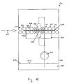
- Fig. 18 is a schematic representation of a treatment station 200, in which the liquid level of the treatment liquid is higher than a transport plane of the material to be treated 203, so that the material to be treated 203 can be transported submerged.
- the material to be treated 203 is transported in a horizontal transport direction 204 through the treatment station.
- roller pairs 211-216 are provided which come into contact with the upwardly or downwardly facing surfaces of the material to be treated 203 in order to transport this.
- an inner container 201 is provided, in which the treatment liquid is accumulated to the (not shown) high level.
- the inner container 201 is surrounded by an outer container 202 so that the outer container 202 catches the treatment liquid flowing over from the inner container 201.
- the treatment liquid is pumped by a pump 210 back into the inner container 201.
- the treatment liquid can be discharged back into the inner container 201 via inflow nozzles 206, 207 or another treatment member.
- pairs of so-called nip rolls 213, 215 are used in the inlet and outlet regions of the inner container 201.
- the pairs of squeezing rollers 213, 215 may, for example, have a cylindrical lateral surface.
- the squeeze rolls 213a, 213b of the pair 213 and the squeeze rolls of the pair of rolls 215 abut against the laundry 203, the free cross section through which the processing liquid can escape from the inner vessel 201 is restricted.
- a desired level of the treatment liquid in the inner container 201 can be adjusted.
- Additional pairs of rollers, such as the pairs of rollers 211, 212, 214 and 216 in the inlet or outlet region of the treatment station can also act as squeezing rollers.
- the direct contact between the nip rollers 213, 215 and the product to be treated 203 which in conventional nip rolls over the entire width, ie the entire extent transverse to the transport direction 204 of the material to be treated 203, lead to damage to the surface of the material to be treated 203.
- Damage to the surfaces of the material 203 to be treated can be caused, for example, by the surface pressure or particles and surface unevenness adhering to the surfaces of the squeezing rollers 213, 215.
- undesirable deflections of the material to be treated 203 may occur in the region of the inflow nozzles 206, 207, for example due to the flow conditions in the treatment station. The deflections may bring the product 203 into contact with other elements of the treatment station.
- the DE 36 03 856 A1 which serves as a basis for the preamble of the independent claims, describes a method and a device for electroplating.
- the device has a cathodically switched pair of rollers which detects and transports a workpiece.
- the device has an anodically connected pair of rollers, which is also rotatably mounted and which rotates at a number of revolutions which is greater than the number of revolutions of the cathodically connected roller pair. Electrolyte is fed to the anodically connected roller pair via a Anspritzregister.
- the DE 195 19 211 A1 describes a treatment device in which a treatment liquid is accumulated. Rollers serve both to transport the material to be treated and to form a liquid Leitraumes, are generated with the regions of different pressure.
- the invention has for its object to provide a method, a treatment station and a plant for treating sheet-like material to be treated, in which or in which the risk of damage to sensitive surfaces of the material to be treated can be reduced.
- the invention is also based on the object of specifying a method for the production of printed circuit boards, in which the risk of damaging sensitive surface areas of the printed circuit board can be reduced.
- the object is achieved by a method, a treatment station and a system for treating flat items to be treated, as indicated in the independent claims.
- the dependent claims define preferred and advantageous embodiments of the invention.
- a method for treating a flat material to be treated which is transported by a plant for electrolytic or wet-chemical treatment of the material to be treated, specified.
- the material to be treated is exposed in a treatment station of the plant to a treatment liquid which covers the material to be treated.
- a roller having a roller surface is positioned such that the roller surface is at least spaced from a useful region of the material to be treated, which extends continuously between edge regions of the material to be treated, so that a gap remains free between the roller surface and the useful region of the material to be treated.
- the roll surface is at least partially disposed in the treatment liquid.
- the roller is driven in rotation in such a way that a relative speed between the roller surface and a surface of the material to be treated is produced at the gap.
- the risk of damage to the surface of the material to be treated can be reduced in the method, since a gap extending between the roller and the useful area of the material to be treated is provided.
- the roller may be spaced from the entire material to be treated. Due to the relative speed on the opposite sides of the gap, the mass transfer to a surface of the material to be treated can be promoted and / or an exit of treatment liquid through the gap can be reduced.
- the remaining gap between the roll surface and the useful area of the material to be treated may be predetermined by the geometry of the plant or, in particular in the case of material to be treated with little inherent rigidity, can result from a force balance.
- the part of the roll surface which is spaced by the gap height from the surface of the material to be treated, can move at a speed which differs in direction and / or amount from a transport speed of the material to be treated.
- the roller may be driven such that the part of the roller surface delimiting the gap moves in the opposite direction to a transport direction of the material to be treated. As a result, a relative speed at the gap can be realized without the roller having to rotate at high speed.
- the roller is advantageously arranged so that its axis of rotation is parallel to a transport plane of the material to be treated.
- the roller may be driven so that an amount of a peripheral speed of the roller surface is different from an amount of the transporting speed of the material to be treated, in particular larger than the amount of the transporting speed.
- the part of the roll surface which is spaced by the gap height of the surface of the material to be treated, move in the transport direction of the material to be treated.
- treatment liquid can be removed from the roller.
- the scraper may be adjusted to adjust an amount of the treatment liquid that is removed from the roller. In this way, it can be controlled how strong the mass exchange caused by the roller is or how much a liquid leakage through the gap is reduced.
- the scraper may be arranged to be evenly spaced from the roll surface. Thereby, a uniform effect over the roller in the axial direction can be achieved.
- the distance between the stripping device and the roller surface may be adjustable.
- the stripping device may be formed as a bar which extends parallel to the axis of the roller and can be positioned at different distances from the roller surface.
- the roller may be provided as a treatment member in the treatment station. This makes it possible to provide the roller, for example, instead of a Anströmdüse.
- a treatment station can be realized with smaller dimensions. Accordingly, a cost saving can be achieved. Also, the forces acting on the material to be treated can be reduced. Energy costs can be reduced. Also, a conservation of the treatment bath can be achieved.
- the minimum gap height between the roll surface and the useful range of the material to be treated can be less than 1 mm, in particular less than 0.7 mm, in particular less than 0.5 mm.
- the minimum gap height may be at least 0.05 mm, in particular at least 0.07 mm, in particular at least 0.09 mm.
- the minimum gap height may also be greater than the stated limits, but should typically be less than 10.0 mm.
- the roller may be arranged such that a mass transfer is increased at a surface to be treated of the material to be treated by the relative speed between the roller surface and the surface of the material to be treated.
- the roller may be arranged such that the effect of the rotation of the roller on the treatment liquid at the surface or in boreholes of the material to be treated results.
- the treatment liquid may be present at the roller up to an operating level of the treatment station.
- the roller may also be arranged completely below the operating level of the treatment station. This allows the use of the roller as a treatment member in a section of the treatment station which may be spaced from the inlet and outlet areas.
- the roller may also be provided in an inlet region or in an outlet region of the treatment station.
- the roller may be provided in an environment of an edge of an inner container of the treatment station.
- the roll surface in this case forms a retaining surface for retaining the treatment liquid. The exit of treatment liquid through the gap can be reduced due to the relative movement at the gap.
- the minimum gap height between the roll surface and the usable region of the material to be treated may be less than 1 mm, in particular less than 0.7 mm, in particular less than 0.5 mm.
- the minimum gap height may be at least 0.05 mm, in particular at least 0.07 mm, in particular at least 0.09 mm.
- Another roll with a further roll surface can be positioned such that a further gap remains free between the useful region of the material to be treated and the further roll surface.
- the roller and the further roller may be arranged on opposite sides of a transport plane of the material to be treated.
- the roller and the further roller may be arranged such that their axes are arranged at the same positions in the transport direction.
- the axes of the roller and the further roller may be spaced apart in the transporting direction.
- the further roller can be driven in rotation such that a part of the further roller surface which forms an edge of the further gap has a speed directed in the transport direction.
- the amount of the peripheral speed of the other roller may be equal to the amount of the transport speed ⁇ 20%.
- the further roller can be driven to rotate in such a way that the roller and the further roller rotate in the same direction.
- a treatment station for treating a flat material to be treated for a system for electrolytic or wet-chemical treatment of the material to be treated is specified.
- the treatment station is set up in such a way that, during operation, a treatment liquid covers the material to be treated.
- the treatment station comprises a roller having a roller surface which is arranged such that the roller surface is at least spaced from a useful region of the material to be treated, which extends continuously between edge regions of the material to be treated, so that a gap remains free between the roller surface and the useful region of the material to be treated.
- the roller is further arranged such that the roller surface is at least partially disposed in the treatment liquid.
- a drive device is set up to drive the roller in such a way that a relative speed between the roller surface and the surface of the material to be treated results at the gap.
- the risk of damage to the surface of the material to be treated can be reduced at the treatment station, since a gap extending between the roller and the useful area of the material to be treated is provided.
- the roller may be spaced from the entire material to be treated. Due to the relative speed at the opposite edges of the gap, the mass transfer to a surface of the material to be treated can be promoted and / or an exit of treatment liquid through the gap can be reduced.
- the drive device can be set up to drive the roller in such a rotating manner that the part of the roller surface delimiting the gap moves in the opposite direction to a transport direction of the material to be treated.
- the drive means may be arranged to rotationally drive the roller so that an amount of a peripheral speed of the roller surface is different from an amount of the transportation speed of the material to be treated, in particular larger than the amount of the transportation speed.
- the roller is advantageously arranged so that its axis of rotation is parallel to a transport plane of the material to be treated.
- the treatment station may comprise a stripping device, in particular a stripping device adjustable relative to the roller, for removing treatment fluid from the roller.
- the roller may be provided as a treatment member in the treatment station.
- the treatment liquid may be present at the roller up to an operating level of the treatment station, or the roller may be arranged completely below the operating level of the treatment station.
- the roller may be provided in an inlet region or in an outlet region of the treatment station, wherein the roller surface is formed as a retaining surface for retaining the treatment liquid.
- the roller may, for example, be provided on an edge of an inner region of the treatment station.
- the treatment station may comprise a further roller having a further roller surface, which is positioned such that a further gap remains free between the useful region of the material to be treated and the further roller surface.
- the roller and the further roller may be arranged on opposite sides of a transport plane of the material to be treated.
- the drive device can be configured to drive the further roller in such a way that a part of the further roller surface, which forms an edge of the further gap, rotates in the transport direction.
- the peripheral speed of the further roller may be equal to the transport speed.
- the drive device can be configured to drive the further roller in such a way that the further roller and the roller rotate in the same direction.
- the treatment station can be designed such that it is set up to carry out the method according to one of the described embodiments or one of the exemplary embodiments.
- the treatment station may further comprise a plurality of transport elements for transporting the material to be treated, which may be formed, for example, as transport rollers or transport rollers.
- an installation for treating a flat material to be treated which comprises the treatment station according to an embodiment or an exemplary embodiment, is specified.
- a method of manufacturing a printed circuit board in which a material for manufacturing the printed circuit board is treated by the method of one embodiment or an embodiment.
- Embodiments of the invention make it possible to remove a treatment liquid from the material to be treated in a system for electrolytic or wet-chemical treatment of a material to be treated or to promote the mass transfer to the surface of the material to be treated.
- a roller surface can be arranged at a distance from a useful region of the material to be treated such that a gap is formed in order to reduce or avoid direct contact of the working region with a solid element.
- Embodiments of the invention can be used in particular in systems in which flat material to be treated is transported with a sensitive surface in a horizontal or substantially in a horizontal transport plane.
- the embodiments are not limited to this field of application.
- Direction or position information relating to the material to be treated shall be indicated by convention in relation to the direction of transport.
- the direction which is parallel or antiparallel to the transport direction when transporting the material to be treated is referred to as the longitudinal direction, the direction lying in the transport plane orthogonal to the transport direction as the width direction of the material to be treated.
- Treatment liquid is understood to mean any liquid to which the material to be treated can be exposed in a system for electrolytic or wet-chemical treatment, in particular a process chemical, a rinsing liquid such as water or the like.
- a transport in a horizontal transport plane can be understood to mean, in particular, a transport of material to be treated in which at least three corners of the material to be treated lie in a horizontal plane. This does not exclude that at least individual section or areas of the material to be treated are located outside the transport plane during transport, for example in the case of a material to be treated with little inherent rigidity.
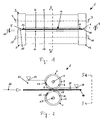
- Fig. 1 is a schematic front view of a device 1 for removing treatment liquid from a material to be treated
- Fig. 2 is a schematic side view of the device 1 along the in Fig. 1 with II-II designated direction.
- the sectional plane of the partially sectioned side view is a vertical plane containing the Transport level along a line intersects at which a useful area of the material to be treated is transported.
- the device 1 comprises a roller 2 and a further roller 3, which are arranged on opposite sides of a transport plane for the material to be treated 10 so that the material to be treated 10 is transported between the roller 2 and the further roller 3.
- the device 1 may be used, for example, as a pair of squeezing rollers 213 or 215 at the treatment station 200 of FIG Fig. 18 be used.
- the roller 2 has a roller surface 4 formed as a retaining surface for retaining treatment liquid, which is provided as a stepped portion of the lateral surface of the roller 2.
- the roller 2 is positioned relative to a transport path of the material to be treated 10 so that a gap 8 between the retaining surface 4 and the material to be treated 10 remains free when the material to be treated 10 is transported past the roller 2.
- the retaining surface 4 forming portion of the lateral surface of the roller 2 may be formed substantially cylindrical.
- the further roller 3 has a further formed as a retaining surface roll surface 14 for retaining treatment liquid, which is provided as a stepped portion of the lateral surface of the roller 3.
- the further roller 3 is positioned relative to the transport path of the material to be treated 10 such that a gap 18 remains free between the further retention surface 14 and the material to be treated 10 when the material to be treated 10 is transported past the roller 3.
- the further retaining surface 14 forming portion of the lateral surface of the roller 3 may be formed substantially cylindrical.
- a useful area 11 of the material 10, which extends over a large part of the width direction of the material 10, does not come with fixed elements of the device 1 in contact.
- the risk of damage to the surfaces of the material to be treated 10 in the useful area 11 can be reduced in this way.
- gaps 8, 18 Due to the cylindrical shape of the retaining surface 4 and the further retaining surface 14, the gaps 8, 18 have a variable in the transport direction 20 of the material to be treated 10 gap height or clear height.
- a minimum gap height 9, 19 of the gaps 8, 18 is determined by those points of the retaining surfaces 4, 14 which are the smallest distance from the the respective roller 2 and 3 opposite surface of the material to be treated 10 have.
- the apparatus 1 can cause a pressure loss due to the tapering of the gaps 8, 18 down to the minimum gap height 9, 19, which can lead to different liquid levels of the treatment liquid at the two opposite sides of the roll 2 in the transport direction 20.
- Fig. 2 schematically shows a treatment liquid 21, which is accumulated on one side of the roller 2 up to a level 22, and a remaining after passing the material to be treated 10 on the device 1 layer of treatment liquid 23, which has a lower level 24.
- the device 1 can be set up such that the treatment liquid 21 on one side of the rollers 2, 3 (in FIG Fig. 2 on the left side of the rollers 2, 3) is accumulated by the retaining surface 4 and the further retaining surface 14 up to the level 22, which is directly at the retaining surface 4 higher than the minimum gap height 9 of the gap 8 and the minimum gap height 19 of the gap 18, each measured from the lower edge of the corresponding gap 8, 18 at the minimum gap height position.
- the rollers 2, 3 of the device 1 can be set up not only for removing liquid from the material to be treated 10, but also for transporting the material 10 to be treated.
- the roller 2 at its two axial ends increased edge portions 5, 6, which are brought into contact with an edge region 12 of the material to be treated 10 when the material to be treated is guided past the rollers 2, 3.
- the raised edge portions 5, 6 can be driven in rotation to transport the material 10 to be treated.
- a shaft 7 is provided, which is rotatably mounted when using the device 1 in a treatment plant for the material 10. By rotation of the edge portions 5, 6 in a direction of rotation 25, the material to be treated 10 can be transported.
- the roller 3 at its two axial ends have raised edge portions 15, 16, which are brought into contact with an edge region 12 of the material to be treated 10 when the material to be treated is guided past the rollers 2, 3.
- the raised edge portions 15, 16 can be driven in rotation to transport the material 10 to be treated.
- a shaft 17 is provided, which is rotatably mounted when using the device 1 in a treatment plant for the material 10. By rotation of the edge portions 15, 16 in a direction of rotation 26, the material to be treated 10 can be transported further.
- the edge portions 5, 6 and / or the edge portions 15, 16 may be in a frictional connection and / or in a form fit with the material to be treated 10 in order to transport this.
- projections may be formed on the edge sections 5, 6 and / or on the edge sections 15, 16, which engage in corresponding recesses of the material to be treated 10 in order to transport the material 10 to be treated.
- the raised edge sections 5, 6 act as transport sections, which can be coupled to the material to be treated 10 for transporting the material to be treated 10.
- the retaining surface 4 is offset relative to the edge portions 5, 6. The increase or in comparison to the radius of the retaining surface 4 larger radius of the edge portions 5, 6 determines the minimum gap height 9.
- the raised edge portions 15, 16 as transport sections, for transporting the material 10 with the treated 10 can be coupled.
- the retaining surface 14 is offset relative to the edge portions 15, 16. The increase or in comparison to the radius of the retaining surface 14 larger radius of the edge portions 15, 16 determines the minimum gap height 19th
- the radii of the edge portions and the retaining surface can be selected suitable for the desired field of application.
- the radius of the retaining surface forming portion of the roller 2, 3 by less than 1 mm, in particular by less than 0.7 mm, in particular by less than 0.5 mm smaller than the radius of the edge portions of the roller 2, 3, which serve as transport sections.
- the radius of the portion of the roller 2, 3 forming the retaining surface may be smaller than the radius of the edge portions of the roller 2, 3 by at least 0.05 mm, in particular by at least 0.07 mm, in particular by at least 0.09 mm Serve transport sections.
- the shaft 7 of the roller 2 and / or the shaft 17 of the further roller 3 may be mounted with a height-adjustable bearing such that a distance of the shaft 7 from the upper surface of the material 10 and / or a distance of the shaft 17 from the lower Surface of the material to be treated 10 can be adjusted.
- the roller 2 and the further roller 3 can be set up so that upon rotation of the edge sections 5, 6 or 15, 16 serving as transport sections, the retaining surfaces 4 and 14 of the respective roller rotate in the same direction as the transport sections of the respective roller.
- the roller 2 or the roller 3 may for example be designed so that both the transport sections and the retaining surface are formed on their surface rotationally fixed to each other. Since the part 4 or 14 of the roller surface, which is spaced from the useful area 11 of the material to be treated 10 and the gap 8 and the gap 18 limited, compared to the transport sections 5, 6 or 15, 16 discontinued, the roller surface of the roller second , 3 a peripheral speed, which is different from the transport speed of the material to be treated 10.
- the transport portions may be rotatably provided relative to the retaining surface, as with reference to FIG Fig. 8 will be explained in more detail.
- the transport sections may be rotatable relative to the retention surface.
- An angular velocity of the retaining surface may be selected depending on an angular velocity of the conveying portions, a radius of the conveying portions, and a radius of the retaining surface forming portion of the roll.
- rollers 2, 3 of the device 1 at its axial ends elevations 5, 6, 15, 16, can be provided either on the roller 2 or on the further roller 3 more than two elevated portions.
- the further raised portions may in particular be arranged on the roller 2 or on the further roller 3 in such a way that they touch the material to be treated 10 at surface areas where such a mechanical contact is not critical.
- surface regions of the material to be treated which extend in the longitudinal direction of the material to be treated 10 can be supported with further elevations of the roller 2 or of the further roller 3, if such contact occurs on one of the sides of the material to be treated should not be critical.
- the additional support effect which is caused by the further increases, can reduce the risk of undesirable contact of the material to be treated 10 in its working area.
- a retaining surface may be provided only on one side a surface of the material to be treated forms a gap.
- a gap-forming retaining surface may be arranged only at the top or only at the bottom of the transport plane.
- a roller may be provided which has a substantially constant diameter. The gap-forming retaining surface provided on the other side can lead to a reduction of the forces exerted on the surfaces of the material to be treated in order to reduce the risk of damage to the surfaces.
- a circumferential surface of a roll having a diameter that is constant, i. which does not vary along the axial direction of the roller serve as a retaining surface defining a gap between the retaining surface and the surface of the material to be treated.
- the design of the gap, in particular the minimum gap height, can be made adjustable by the roller is mounted with a bearing which is adjustable in height relative to the transport plane. It is also possible to provide two such rolls in order to remove liquid at the top and at the bottom of the material to be treated, a gap being formed between the corresponding roll and the material to be treated.
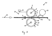
- Fig. 3 is a schematic side view of a device 31 for removing treatment liquid according to another embodiment.
- the device 31 may, for example, in the outlet region of the treatment station 200 of Fig. 18 instead of the pairs of squeezing rollers 214, 215, 216 may be used.
- Elements or devices of the device 31, which correspond in their function and / or configuration elements or devices of the device 1, are provided with the same reference numerals and will not be explained again in detail.
- the device 31 comprises a roll surface formed as a retaining surface 4 for retaining liquid.
- the device 31 is set up such that the retaining surface 4 with the surface of a material to be treated 10 which is opposite it
- the retaining surface 4 is provided on the rotatably mounted roller 2.
- the roller 2 can be as with reference to Fig. 1 and 2 be designed described. In particular, as with reference to Fig. 1 and 2 has been described, the peripheral speed of the roll surface at the gap 8 from the transport speed of the material to be treated 10 different.
- the retaining surface 4 removes treatment liquid from the treated material 10 transported past the retaining surface 4. Since the gap 8 permits the passage of treatment liquid in one embodiment, treatment liquid 34 may also be present on the material to be treated 10 after it has passed the roller 2 with the retaining surface 4 Has.
- the device 31 further comprises an on-flow device 32 with a nozzle arrangement.
- the on-flow device 32 is arranged in the transport direction at a distance from the roller 2 and the roller 2 provided on the retaining surface 4.
- the on-stream device 32 is downstream in the transport direction, i. in the transport direction, the roller 2 with the retaining surface 4 is arranged.
- the onflow device 32 is set up to remove a portion of the treatment liquid 34, which has remained on the material to be treated 10 after passing through the gap 8, from the material to be treated 10.
- the onflow device 32 can be set up to remove a large part of the treatment liquid 34, which has remained on the item to be treated 10 after passing through the gap 8, from the item to be treated 10.
- the onflow device 32 can output a fluid flow 33, in particular a gas flow, for example an air flow, in order to blow off the treatment fluid 34 from the material to be treated 10 or otherwise to remove it with the fluid flow 33.
- the fluid flow 33 can have at least one flow component in the direction of the gap-forming retaining surface 4 of the device 31 (in FIG Fig. 3 a leftward component). At the retaining surface 4, the treatment liquid can flow laterally from the material to be treated.
- the inflow device may also be arranged such that the fluid flow 33 has a flow component which is directed parallel to the transport plane and transversely to the transport direction 20, ie parallel to the axial direction of the roller 2 on which the retention surface 4 is formed. In this way, the treatment liquid 34 can be removed laterally from the item to be treated 10.
- the on-stream device 32 can extend over the entire width of the material 10 to be treated, i. on the extent of the material to be treated 10 transverse to the transport direction, extend over the material to be treated 10.
- the onflow device 32 may have one or more nozzle openings.
- the nozzle openings may be formed, for example, as a continuous slot, a plurality of slots or a plurality of bores, which is or are formed in the width direction of the material to be treated 10 on the onflow device 32.
- the onflow device 32 can be designed such that the distance between the nozzle openings to the surface of the material to be treated 10 over the entire width of the material to be treated is substantially equal.
- the onflow device 32 may comprise a straight channel body, which is directed parallel to the transport plane and transversely to the transport direction 20.
- the channel body may alternatively also be aligned parallel to the transport plane and obliquely to the transport direction 20.
- the on-flow device 32 may be formed such that a widthwise portion of the processed material 32 is located closer to the gap-forming retention surface 4 than an edge portion of the flow-through device 32.
- the flow-type device 32 may have a shape that is in plan view from a direction perpendicular to the transport plane (ie in Fig. 3 when viewed vertically from above on the transport plane) has a convex to the formed by the retaining surface 4 gap 8 out.
- the on-flow device 32 may have a V-shape in plan view, the tip of which points towards the retaining surface 4.
- a so-formed on-flow device is adapted to output the fluid flow with a velocity component in the direction of an edge of the material to be treated in order to effectively convey the treatment liquid to the edge of the material to be treated and so to remove.
- the on-flow device 32 can be set up to output a gas stream, in particular an air stream, and to feed the material to be treated therewith.
- the onflow device 32 can be set up such that an outflow velocity of the gas stream 33 is at least 2 m / sec, in particular at least 10 m / sec, in particular at least 30 m / sec.
- the on-stream device 32 can also be set up to dispense a liquid flow and to feed the material to be treated therewith.
- the on-stream device 32 can be set up so that an outflow velocity of the liquid stream 33 is at least 0.1 m / sec, in particular at least 1 m / sec, in particular at least 3 m / sec.
- the onflow device 32 can be set up such that an outflow direction of the fluid flow 33 can be parallel or oblique to the surface of the material to be treated.
- the onflow device 32 may be designed such that the fluid flow flows out of the nozzle openings of the onflow device 32 in the direction of the gap 8 and / or transversely to the transport direction in the direction of an edge of the material 10 to be treated.
- the outflow direction can also be directed perpendicular to the surface of the material 10 to be treated.
- the on-stream device 32 may be configured so that the fluid stream 33 does not pass through the gap 8, i. does not enter the treatment liquid accumulated on the opposite side of the gap-forming retaining surface 4. In this way, it can be avoided or suppressed that the fluid flow 33 causes a bubble formation in the treatment liquid 21.
- the outflow velocity and / or the outflow direction of the fluid flow 33 from the onflow device 32 can be adjusted accordingly, for example.
- the device 31 may be configured so that a distance or the different distances between the gap 8 and the nozzle opening or the nozzle openings of the onflow device 32 is at most 100 mm and at least 10 mm.
- the device 31 may further comprise a roller surface formed as a retaining surface 14 disposed below the transport plane and formed on another roller 3.
- a device 31 for removing treatment liquid in which the onflow device 32 is arranged downstream of the roller 2 with the gap-forming retaining surface 4 in the transport direction of the material to be treated 10
- a device for holding off treatment liquid can also be designed such that the onflow device in the transport direction of the material to be treated before or upstream of the gap forming Retaining surface is arranged.
- Such a device can be used in particular in an inlet region of a treatment station.
- the Anström worn 32 may alternatively or additionally be provided below the transport plane to blow off liquid from an underside of the material 10 or otherwise with the discharged from the Anström personality fluid stream 33 of the treated 10 to remove.
- the on-flow device is provided below the transport plane, it can be configured such that the fluid flow generated by the onflow device has a velocity component parallel to the transport direction, which is directed away from the gap-forming retaining surface.
- the fluid flow generated by the onflow device may have a velocity component directed in the transport direction.
- a tramp sport element can be provided at the corresponding position below the transport plane.
- an on-flow device is provided for removing treatment liquid below the transport plane, at the corresponding position above the transport plane a Trannsportelement be provided.
- the transport element and the onflow device can be arranged at the same position in the transport direction on opposite sides of the transport plane.
- the transport element can be set up, for example, to support and / or transport the item to be treated.
- the transport element may be formed as a roller.
- the roller may have a stepped retaining surface, but may also have a substantially constant diameter in the axial direction.
- the transport element can also be designed as a wheel axle, on which a plurality of wheels are provided. The wheels can be designed to touch the material to be treated for transporting the material to be treated.
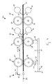
- Fig. 4 is a schematic side view of an outlet region 41 of a treatment station.
- a discharge area 41 may be at the treatment station 200 of Fig. 18 be provided at one end of the inner container 201, where the Material to be treated leaves the treatment station.
- a material to be treated 10 from a treatment area 42, in which a treatment liquid 21 covers the material to be treated is transported further in a transport direction 20.
- the outlet region 41 comprises a plurality of devices 43, 44 and 45 for removing treatment liquid from the item to be treated.
- the devices 43, 44 and 45 for removing the treatment liquid are arranged spaced from each other in the transport direction 20 along a transport path of the material 10 to be treated.
- Each of the devices 43, 44 and 45 may have a retaining surface, which is arranged relative to the transport plane so that a gap between the retaining surface and the surface of the material to be treated 10 opposite it is formed.
- the devices 43, 44 and 45 may be formed as devices for removing treatment liquid according to an embodiment.
- the device 43 may comprise a pair of rollers 51, 52 arranged so that the material to be treated 10 may be passed therebetween.
- a gap-forming retaining surface for retaining the treatment liquid may be formed such that a gap is formed between the retaining surface and the surface of the material 10 facing it, as the material to be treated passes by the rollers 51, 52 becomes.
- at least one of the rollers 51, 52 may have raised edge regions for transporting the material to be treated 10 and a stepped-down support surface provided therebetween.
- the device 43 may, for example, as with reference to Fig. 1 and 2 explained device 1 may be formed.
- At least the roller 51, 52, on which the gap-forming retaining surface is formed is driven so that the peripheral speed of the roller surface at the edge of the gap, ie along the line at which the roller surface is separated from the material 10 by the minimum gap height , in the direction and / or amount of the transport speed of the material 10 is different.
- the device 44 may have a roller 53 arranged upstream of the transport plane and an onrun device 54 and a roller 55 and an upstream device 56 arranged below the transport plane.
- a gap-forming retaining surface for retaining the treatment liquid may be formed such that a gap is formed between the retaining surface and the surface of the material 10 facing it as the material to be treated moves past the rolls 53, 55 becomes.
- at least one of the rollers 53, 55 has raised edge regions for transporting the material to be treated 10 and a stepped-down retainer surface provided therebetween, as with reference to FIG Fig. 1 and 2 explained.
- the onflow devices 54 and 56 flow the material 10 to be treated with a fluid flow 33, for example, an air flow to remove remaining on the treated treatment treatment liquid.
- a fluid flow 33 for example, an air flow to remove remaining on the treated treatment treatment liquid.
- the fluid streams 33 emitted by the onflow devices 54 and 56 can be directed so that they move the treatment liquid in the direction of an edge of the material to be treated and thus remove it.
- the device 45 may comprise a roller 57 arranged upstream of the transport plane and an on-flow device 58 and a roller 59 and onflow device 60 arranged below the transport plane.
- a gap-forming retaining surface for retaining the treatment liquid may be formed such that a gap is formed between the retaining surface and the surface of the material 10 facing it as the material to be treated moves past the rolls 57, 59 becomes.
- at least one of the rollers 57, 59 can have raised edge regions for transporting the material to be treated 10 and a remote retaining surface provided therebetween, as with reference to FIG Fig. 1 and 2 explained.
- the onflow devices 58 and 60 flow the material 10 to be treated with a fluid flow 33, for example an air flow, in order to remove treatment liquid remaining on the material to be treated.
- a fluid flow 33 for example an air flow
- the fluid streams 33 emitted by the onflow devices 58 and 60 can be directed so that they move the treatment liquid in the direction of an edge of the material to be treated and thus remove it.
- rollers 53, 55, 57, 59 at least those which form a gap between the corresponding roller and the material to be treated, can be rotated so that the peripheral speed of the roller at the gap in amount and / or direction of the transport speed of the material to be treated 10th is different.
- the gap-forming retaining surfaces of the devices 43, 44 and 45, which passes through the material to be treated 10 in succession, may have a different configuration.
- the gaps at the devices may become increasingly narrow.
- the device 43 may be configured such that a gap having a first minimum gap height is formed between the retaining surface of the device 43 and the opposite surface of the material to be treated 10, while the device 43 arranged downstream of the device 43 in the transport direction may be that a gap is formed with a second minimum gap height between the retaining surface of the device 44 and the opposite surface of the treated material 10.
- the second minimum gap height at the device 44 may be smaller than the first minimum gap height at the device 43, ie the gaps may have a smaller height in the outlet region of the treatment station from one device to another device for removing treatment liquid downstream in the transport direction.
- the device 43 delimiting the treatment area 42 is arranged to adjust a level difference 74 of the treatment liquid between the opposite sides of the roller 51 in the transporting direction.
- the treatment liquid 21 is accumulated up to a level 71, while in the adjacent area on the other side of the roller 51 the treatment liquid is accumulated up to a level 72.
- the device 44 which is arranged downstream of the device 43 in the transport direction, is set up such that treatment liquid is removed from the item to be treated 10 when the item to be treated 10 passes through the rollers 53, 55.
- Treatment liquid 73 which is still present after passing the material to be treated 10 on the rollers 53, 55 on the material to be treated 10, 56 is at least partially removed by the Anström wornen 54, 56.
- the device 45 which is arranged downstream in the transport direction of the device 44, a further part of the treatment liquid can be removed from the material to be treated, which may still be present on the material to be treated 10 after passing through the device 44.
- treatment liquid can be reliably removed from the material to be treated 10 even if gaps remain between the retention surfaces and the material 10 to be treated.
- a weir 47 is provided between a bottom 46 of an inner container of the treatment station and arranged below the transport plane roller 52 of the device 43.
- a level difference 74 between the liquid levels 71, 72 on the two sides of the device 43 can be adjusted.
- 47 openings 61 are formed in the weir, for example in the form of slots, holes or slots. The openings 61 may be closable to adjust the fluid passage through the weir 47 and thus adjust the level difference 74 between the fluid levels 71 and 72.
- the level 72 in the region adjacent the treatment area 42 is determined by a balance of incoming and outgoing streams of treatment liquid.
- one or more openings for example closable bores, can be provided in the floor 46 between the weirs 47, 48.
- a basic setting for a desired level 72 in the area adjacent to the treatment area 42 can be selected.
- overflow weirs may be provided on elements laterally delimiting the treatment station, for example, on bearing receivers intended for supporting the rollers 51, 52, 53 and 55. Additional inflowing liquid quantities can be removed via the overflow weirs.
- treatment liquid can be conveyed into the treatment area 42 with a pump (not shown).
- a weir 48 is provided between the bottom 46 of the inner container of the treatment station and arranged below the transport plane roller 55 of the device 44.
- the weir 48 need not have closable openings for adjusting the liquid level.
- the weir 48 helps to reduce drainage of the treatment fluid from the treatment area.
- modifications of the outlet region 41 may be realized.
- device 45 may be omitted.
- two devices for removing treatment liquid can be provided in the outlet region. At least the last in the transport direction of these devices may have a flow device.
- the onflow device can be provided at least above the transport plane.
- a plurality of fluid removal devices may be provided having a weir having one or more openings for adjusting a level difference.
- the weir may each have a configuration as explained with reference to the weir 47.
- two devices, each with at least one roller may be provided, for example, in the inlet or outlet region, which has a retaining surface for retaining liquid, which has a gap with the past it Material to be treated, wherein in each of the devices below the transport plane, a weir is provided with one or more openings as described for the weir 47.
- a further device Spaced in the direction of transport to these two devices, a further device may be provided which has a configuration corresponding to the device 44. In this way, for example, at least two regions can be formed with a level of the treatment liquid lowered relative to the treatment region in an inlet or outlet region.
- each of the devices for removing liquid may be formed so a retaining surface is provided only at the roller provided above the transport plane, which leaves free a gap between the retaining surface and the material to be conveyed past it.
- the rolls provided below the transport plane can have a diameter which is constant in the axial direction of the rolls.
- one of the flow devices 54, 56 may be replaced by a transport element.
- the transport element can be set up to support and / or transport the item to be treated.
- the transport element may be formed, for example, as a roller or as a wheel axis.
- one of the onflow devices 58, 60 may be replaced by a transport element.
- the transport element can be set up to support and / or transport the item to be treated.
- the transport element may be formed, for example, as a roller or as a wheel axis.
- one of the on-conveyor devices 56, 60 provided below the transport plane may be configured such that the fluid stream 33 generated by the on-stream device 56, 60 has a velocity component that points in the outflow region 41 in the transport direction.
- Fig. 5 is a schematic side view of a discharge area 81 of a treatment station.
- a discharge area 81 may be at the treatment station 200 of Fig. 18 be provided at one end of the inner container 201, where the material to be treated leaves the inner container 201.
- Elements or devices of the outlet region 81 which correspond in their function and / or configuration to elements or devices outlet region 41, are provided with the same reference numerals and will not be explained again in detail.
- the liquid level 91 in the treatment area 82 may, for example, be arranged at least 15 mm above the transport level.
- the spout area 81 is provided with a plurality of devices 83, 44 and 45 for removing or holding treatment liquid.
- the device 83 comprises rollers 84, 85, which are arranged so that the material to be treated 10 can be carried out therebetween.
- a gap-forming retaining surface for retaining the treatment liquid may be formed such that a gap is formed between the retaining surface and the surface of the material 10 facing it as the material to be treated moves past the rollers 84, 85 becomes.
- at least one of the rollers 84, 85 may have raised edge regions for transporting the material to be treated 10 and a stepped-down retainer surface provided therebetween.
- the pair of rollers 84, 85 may be, for example, as described with reference to FIGS Fig. 1 and 2 explained device 1 may be formed. At least the roller 84, 85, on which the gap-forming retaining surface is formed, is driven so that the peripheral speed of the roller surface at the gap, ie along the line at which the roller surface is separated from the material to be treated by the minimum gap height of the transport speed of the material to be treated 10 in the direction and / or amount differs.
- the device 83 above the roller 84 has a further retaining element 86.
- the further retaining element 86 is designed to assist in the accumulation of the treatment liquid at a high liquid level in the treatment area 82 by serving as a wall for the accumulated liquid.
- the further retention member 86 may be formed as a roller that is complementary to the roller 84 so that the rollers 84, 86 close tightly and allow little or no passage of fluid between the rollers 84, 86.
- Other Embodiments for the further element 86 are possible, for example in the form of an upstand.
- the device 83 is arranged to adjust and maintain a level difference 97 of the treatment liquid between the level 91 in the treatment area 82 and a level 92 in the adjacent area on the other side of the device 83 via the device 83.
- the downstream device 44 in the transport direction of the device 83 removes further treatment liquid from the item to be treated 10 when it passes the device 44. Instead of the level 92, there is only a smaller amount of treatment liquid 93 on the item to be treated 10 when the product 10 has passed the pair of rollers of the apparatus 44.
- the downstream in the transport direction of the device 44 device 45 may remove further treatment liquid from the material 10, if this is still necessary after passing through the device 44.
- closable openings 61 are provided in the weir 47.
- the level 92 in the region adjacent to the treatment area 82 is determined by a balance of incoming and outgoing streams of treatment liquid.
- one or more openings 96 for example closable bores, can be provided in the floor 46 between the weirs 47, 48.
- a suitable choice of the openings 61 opened in the weir 47 and the openings 96 opened in the bottom 46 a basic setting for a desired level 92 in the region adjacent to the treatment area 82 can be selected.
- overflow weirs may be provided on elements laterally delimiting the treatment station, for example, on bearing mounts intended to support the rollers of the devices 83 and 44. Additional inflowing liquid quantities can be removed via the overflow weirs.
- a stream 94 of treatment liquid is conveyed into the treatment area 82 with a pump 94.
- devices for removing or holding treatment liquid can also be provided correspondingly in an inlet area of a treatment station.
- a plurality of spaced apart in the transport direction devices for removing or holding treatment liquid can be provided to prevent the treatment liquid flows onto the material to be treated before it is introduced into the inlet region in the treatment station.
- the configuration of the gap-forming retention surface can be suitably selected depending on the specific fields of application.
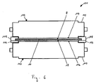
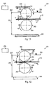
- Fig. 6 is a schematic front view of a device 101 for removing or holding treatment liquid according to another embodiment.
- the device 101 comprises a roller 102 and a further roller 103.
- the roller 102 and the further roller 103 are arranged so that a material to be treated 10 can be transported between the rollers 102 and 103.
- a lateral surface of the roller 102 has a retaining surface 104, which is designed to retain the treatment liquid.
- the roller 102 with the retaining surface 104 is formed so that a gap 8 between the retaining surface 104 of the roller 102 and one of these opposite surface of the material to be treated 10 remains free when the material to be treated 10 is guided past the roller 102.
- Axial end portions 105 of the roller 102 are formed with a smaller diameter than the retaining portion 104 defining the central portion of the roller 102 to act as transport portions for transporting the material to be treated 10 when it is supported at its longitudinal edges with support rails.
- a lateral surface of the further roller 103 has a further retaining surface 106, which is designed to retain the treatment liquid.
- the further roller 103 with the further retaining surface 106 is formed such that a gap 18 remains free between the further retaining surface 106 of the further roller 103 and an opposite surface of the material to be treated 10 when the material to be treated 10 is guided past the further roller 103.
- Axial end portions 107 of the further roller 103 are formed with a smaller diameter than the further retaining surface 106 defining central portion of the further roller 103 to act as transport portions for transporting the material to be treated 10 when it is supported at its longitudinal edges with support rails.
- rollers 108, 109 which support the material to be treated for transporting the material to be treated 10.
- Such support rails 108, 109 can in particular when transporting material to be treated with low intrinsic stiffness can be used to give the material to be treated additional stability.
- the roller 102 and further roller 103 of the device 101 are designed such that their smaller diameter axial end sections 105, 107 come into contact with the support rails 108, 109. By rotation of the roller 102 and the further roller 103, the material to be treated 10 can be transported on the support rails 108, 109.
- the retaining surfaces 104, 106 of the rollers 102, 103 are offset from the transport section provided at the axial end of the rollers 102, 103 such that gaps 8, 18 with the desired minimum gap height between the retaining surfaces 104, 106 and the surfaces opposite them of the material to be treated 10 are formed when the material to be treated 10 is guided past the retaining surfaces 104, 106.
- the rollers 102, 103 do not touch the material 10 directly.
- the transport of the material to be treated 10 via a coupling of the transport sections 105, 107 with the support rails 108, 109, where the material to be treated 10 is supported.
- the roll surface of the roll 102 defining the gap 8 on one side, which forms the retaining surface 104 has a peripheral speed which is smaller than the transport speed of the material 10 to be treated.
- the roller surface 103 bounding the gap 18 on one side of the roller 103, which forms the retaining surface 106, has a peripheral speed which is smaller than the transport speed of the material 10 to be treated.
- the rollers 102, 103 may be configured to contact the material 10 to be treated in an edge area adjacent to the support rails 108, 109 for transporting.
- increased transport sections can be provided on the rollers 102, 103, which contact the material to be treated next to the support rails 108, 109.
- the rolls 102, 103 can furthermore be set up such that a gap for displacing liquid is formed between the rolls 102, 103 and the support rails 108, 109.
- corresponding recessed grooves or grooves for squeezing liquid from the support rails to the rollers 102, 103 can be provided relative to the transport sections of the rollers.
- the gap formed between the rollers and the support rails may have a minimum gap height which is less than 1 mm, in particular less than 0.7 mm, in particular can be less than 0.5 mm.
- the gap formed between the rollers and the support rails may have a minimum gap height, which may be at least 0.05 mm, in particular at least 0.07 mm, in particular at least 0.09 mm.
- the apparatus 101 for squeezing liquid from retained laundry may further comprise an on-stream device.
- the on-stream device can as described with reference to Fig. 3 be explained explained.
- the onflow device can be designed such that the fluid flow output by the onflow device also removes treatment fluid from the support rails.
- passages may be provided which allow passage of liquid through the support rails transversely to the transport direction.
- the rollers 102, 103 may be arranged to exert force on at least one of the longitudinal edges provided retaining rails 108, 109 with a force component which lies in the transport plane and is directed transversely to the transport direction.
- the force may be directed so that the support rails 108, 109 provided on the opposite longitudinal edges are pressed away from one another in order to tension the material to be treated 10 transversely to the transport direction.
- the holding rail 108 and / or 109 can, for example, have one or more magnets, in particular permanent magnets, on at least one longitudinal edge of the material to be treated.
- the roller 102 provided above the transport plane and / or the roller 103 provided below the transport plane may have one or more magnets to exert an electromagnetic force on the support rail.
- the force may be directed so that the retaining rails are pressed resiliently away from one another on the opposite longitudinal edges of the material 10 to be treated.
- Fig. 7 is a schematic side view of a device 111 for removing or holding treatment liquid.
- the retaining surfaces are not provided on a rotatably mounted roller.
- the device 111 in combination with a roller with the reference to Fig. 1-6 be described embodiment provided in a treatment station.
- the device 111 comprises two substantially cuboidal elements 112, 113, which can be used as inserts in a plant for the treatment of a material 10 to be treated.
- Insert 112 is above the transport plane and insert 113 is below arranged the transport plane.
- a surface of the inserts 112, 113 serves as a retaining surface which retains treatment liquid.
- the inserts 112, 113 of the device 111 are arranged relative to a transport path of the material to be treated 10 so that between one of the upper surface of the material to be treated 10 and one of these facing side surface 114 of the insert 112, a gap 115 remains free if the material to be treated 10 on the device 111 is passed, and that between the lower surface of the material to be treated 10 and one of these facing side surface 117 of the insert 113, a gap 118 remains free when the material to be treated 10 is passed to the device 111.
- the side surface 114 of the insert 112 and the side surface 117 of the insert 117 may have a planar configuration such that the gaps 115 and 118 extend along the transport direction at a constant gap height.
- the inserts 112, 113 of the device 111 have an inlet region which opens against the transport direction 20 and is formed by chamfers 116, 119 on the inserts 112, 113.
- Such an inlet region can be used, for example, for guiding treated articles with low inherent rigidity, for example foils.
- the device 111 with the inserts 112, 113 can be used for damming the treatment liquid 21 in a system for the electrolytic or wet-chemical treatment of the material 10 to be treated. If the item to be treated 10 from a on a first side (left in Fig. 7 ) of the inserts arranged treatment area in which the treatment liquid 21 is accumulated up to a level 121, is guided past the inserts 112, 113, a layer of treatment liquid with a smaller thickness 122 remains on the item to be treated 10th
- the inserts 112, 113 can be suitably configured depending on the structural conditions of the installation in which the device 111 is used.
- the inserts 112, 113 may be configured such that the gaps 115, 118 in the transport direction 20 are as long as possible.
- the inserts 112, 113 may be non-rotatably mounted in the system for electrolytic or wet chemical treatment.
- the inserts 112, 113 may be mounted in the system in particular also at a fixed position in the transport direction.
- the inserts 112, 113 may be mounted so that they are vertically movable against each other.
- a cuboid insert is provided above the transport plane, while below the transport plane a roller is provided for transporting the material to be treated.
- the cuboid insert may for example have the same configuration as the insert 112 of the device 111.
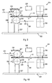
- Fig. 8 is a schematic side view of a treatment station 131, in which in an inlet region, a pair of rollers 132, 133 and in a discharge region, a further pair of rollers 134, 135 is provided.
- the roller 132 in the inlet region is above the transport plane and the roller 133 in the inlet region is arranged below the transport plane of a material to be treated 10.
- the roller 134 in the outlet region is above the transport plane and the roller 135 in the outlet region is arranged below the transport plane of a material to be treated 10.
- Each of the rollers 132-135 has at its axial ends transport sections in the form of elevations 5, 15 for transporting the material to be treated. Between the transport sections provided at the ends, a retaining surface 4, 14 with a smaller diameter is formed. As with reference to Fig. 1 and 2 explains, designed as a retaining surface 4, 14 surface of the rollers forms a gap with the passing past the rollers to be treated, which extends in the width direction of the treated material.
- the various sections of the roller 132 in the inlet region are driven in rotation so that the transport sections 5 and the retaining surface 4 arranged therebetween of the roller 132 provided above the transport plane rotate in the same direction.
- the various sections of the roller 133 in the inlet region are driven in rotation so that the transport sections 15 and the retaining surface 14 arranged therebetween of the roller 133 provided below the transport plane rotate in the same direction.
- the direction of rotation 141 of the transport sections 5 of the roller 132 provided above the transport plane is selected such that the transport sections 5 move at their points of contact with the item to be treated 10 in the transport direction 20 in order to transport the item to be treated 10 in the transport direction 20.
- the direction of rotation 143 of the transport sections 15 of the roll 133 provided below the transport plane is selected so that the transport sections 15 move at their points of contact with the item to be treated 10 in the transport direction 20 in order to transport the material 10 in the Transport direction 20 to transport.
- the retaining surface 4 of the roller 132 provided above the transport plane is rotated in the same direction as the transport sections 5 of the roller 132 in a direction of rotation 142 such that the portion of the retaining surface 4 that is just facing the material to be treated 10 moves in the direction of the higher liquid level (in FIG Fig. 8 to the right).
- the retainer surface 14 of the roller 133 provided below the transport plane is rotated in the same direction with the transport sections 15 in a direction of rotation 144 so that the portion of the retainer surface 14 which is currently facing the material to be treated 10 moves in the direction of the higher liquid level (in FIG Fig. 8 to the right).
- rollers 132, 133 By suitable design of the rollers 132, 133, a sufficiently high liquid level 136 can be accumulated while the movement of the retention surfaces 4 against the high liquid level region sufficiently reduces the passage of liquid through the gaps formed on the retention surfaces 4 of the rollers 132, 133.
- the rollers 132, 133 may be configured such that a gap with a minimum gap height of less than 0.3 mm, for example approximately 0.1 mm, is formed between the retaining surface 4, 14 and the surface of the material 10 facing the retaining surface ,
- the transport sections can be increased by less than 0.3 mm, for example by about 0.1 mm, relative to the retention surface.
- the transport sections 5, 15 of the rollers 134, 135 are rotated with a direction of rotation 145, 147 so that the transport sections 5, 15 move at their points of contact with the item to be treated 10 in the transport direction 20.
- the roller 134 provided above the transport plane can be designed such that the retaining surface 4 of the roller 134 is rotatable relative to the transport section 5 of the roller 134 is.
- the roller 135 provided below the transport plane may be formed so that the retaining surface 14 of the roller 135 is rotatable relative to the conveying portion 15 of the roller 135.
- the retaining surface 4 of the roller 134 provided above the transport plane can be rotated in a direction of rotation 146 which is opposite to the direction of rotation 145 of the transport section 5 of this roller 134.
- the retaining surface 14 of the roller 135 provided below the transport plane can be rotated in a direction of rotation 148 which is opposite to the direction of rotation 147 of the transport section 15 of this roller 135. In this way, in the outlet region, a rotation of the retaining surfaces 4, 14 such take place that the portion of the retaining surface 4 of the roller 134 provided above the transport plane, which straight to the item of laundry 10, in the direction of the higher liquid level (in Fig. 8 to the left). Similarly, the retaining surface 14 of the roller 135 can be rotated in the opposite direction to the transport section 15 so that the portion of the retaining surface 14 of the roller 135, which is just facing the material to be treated 10, in the direction of the higher liquid level (in Fig. 8 to the left).
- the roller surface of the roller 134 serving as the retaining surface 4 is thereby rotated such that the points of the roller surface closest to the transport plane in one direction (in FIG Fig. 8 to the left) opposite to the transport direction of the material 10 to be treated. In this way, a relative movement between the roller surface 4 at the upper edge of the gap 8 and the material 10 is generated.
- the roller surface of the roller 135 serving as the retaining surface 5 is rotated such that the points of the roller surface nearest the transport plane in one direction (in FIG Fig. 8 to the left) opposite to the transport direction of the material 10 to be treated. In this way, a relative movement between the roller surface at the lower edge of the gap 9 and the material 10 is generated.
- the rollers 134, 135 in the outlet region can also be designed such that a gap having a minimum gap height of less than 0.3 mm, for example approximately 0.1 mm, between the retaining surface 4, 14 and the surface of the material 10 facing the retaining surface is trained.
- the transport sections can be increased by less than 0.3 mm, for example by about 0.1 mm, relative to the retention surface.
- one or more inflow devices can be provided in each case in order to remove treatment fluid leaving the gap with a fluid flow, as with reference to FIG Fig. 3 explained.
- roller pairs in the inlet region and / or outlet region it is possible to reduce leakage of liquid through the gaps, which remain free during transporting the material to be treated, that in the inlet region and / or in the outlet region of the treatment station no flow device for blowing off treatment liquid is provided.
- a plurality of devices for removing or holding treatment liquid can also be provided in each case, as with reference to FIG Fig. 4 and 5 explained.
- the devices and methods according to various embodiments make it possible to remove a treatment liquid from the item to be treated or to increase the mass transfer to the item to be treated in a system for electrolytic or wet-chemical treatment of items to be treated, wherein a direct contact between solid elements and a useful portion of the material to be treated can be reduced or avoided.
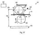
- Fig. 9 is a partially sectioned side view of a discharge area 221 of a treatment station.
- the illustrated liquid removal apparatus may include a pair of rollers 231, 232, a wiper 235, a blower 236, and a driver 238.
- the device may, for example, instead of the squeezing rollers 214 and / or 215 at the treatment station 200 of Fig. 18 be used.
- the treatment station has an inner tub with a bottom 222.
- the treatment liquid has an operating level 223 with a height 224 opposite the bottom 222 in a region of the treatment station.
- the operating level 223 is set so that the laundry 10 is covered by the treating liquid before passing through the pair of rollers 231, 232.
- the height 226 of the treatment liquid downstream of the weir 227 is less than the height 224 upstream of the weir.
- the rollers 231, 232 are designed so that they are at least spaced from the working area of the material to be treated 10, which extends continuously between opposite edge portions.
- the roller 231 is arranged above the transport plane of the material to be treated.
- the roller 232 is arranged below the transport plane of the material to be treated.
- Each of the rolls 231, 232 is covered with treatment liquid at least at a part of its circumference.
- the rollers 231, 232 may be formed so that they are spaced from the entire material to be treated 10, when the material to be treated 10 is guided past the rollers 231, 232.
- the rollers 231, 232 may be configured such that they do not participate in the transport of the material 10 to be treated.
- the rollers 231, 232 may have a cylindrical roller surface 228 and 229, respectively.
- a gap between the roller surface 228 of the roller 231 and the material to be treated 10 continuously extends between edge portions of the material to be treated 10 in a width direction.
- a further gap between the roller surface 229 of the roller 232 and the material to be treated 10 extends continuously between edge regions of the material to be treated 10 in the width direction.
- the rollers 231, 232 are driven in rotation by the drive device 238.
- the drive means may include an actuator, such as a motor, and suitable components for transmitting the torque from the actuator to the rollers 231, 232.
- the drive means 238 for the rollers 231, 232 may comprise components which are simultaneously part of drive means for other elements, for example for transport rollers.
- the drive device 238 may be provided within the treatment station. At least the motor of the drive device 238 may be encapsulated.
- the drive means 238 drives the roller 231 to have a peripheral speed of an amount v1.
- the speed vector 234 of the circumferential speed is directed against the transport speed vT of the material to be treated. Due to the viscous resistance between the roller 231 and the treatment liquid, the exit of treatment liquid through the gap can be reduced.
- the roller 231 arranged above the transport plane can be driven in such a way that the roller surface moves in the direction of the higher level at the gap-defining line.
- the amount of the speed v1 and the rotational speed of the roller 231 may be adjusted depending on a desired level difference of the treatment liquid between both sides of the roller.
- the drive means 238 drives the roller 232 to have a peripheral speed of an amount v2.
- the roller 231 and the roller 232 are driven to rotate in the same direction.
- the circumferential speed v2 of the second roller 232 may be equal in magnitude to the transport speed of the material to be treated, vT, ⁇ 20%. This can reduce the risk that a material to be treated 10 with low inherent rigidity is so strongly deflected that it comes with one of the rollers 231, 232 in impermissible contact can be reduced.
- the roller 232 may also be driven such that the amount of the peripheral speed v2 is greater than the amount of the transport speed vT.
- the drive device 238 can drive the roller 231 so that the roller 231 entrains treatment liquid.
- the amount of the entrained treatment liquid is dependent on surface properties of the roller 231, in particular on a surface roughness, on the rotational speed and on the diameter of the roller 231.
- the scraper 235 removes entrained treatment liquid from the roller 231.
- the scraper 235 may be formed, for example, as a bar which extends parallel to the axis of the roller 231.
- the scraper 235 may be configured to compensate for a variation of the processing liquid entrained by the roller 231 along the axial direction of the roller 231.
- the scraper 235 may be at a constant distance from the roller surface 228 along the axial direction of the roller 231.
- the scraper 231 may be formed so as not to completely remove the processing liquid from the roller 231, so that a film of the finely-sized treatment liquid is formed around the roller 231 due to the rotation of the roller 231.
- the scraper 235 may be formed so that the film of the treatment liquid around the roller 231 reduces the effective cross section of the gap between the roller 231 and the treatment liquid 10 for the discharge of treatment liquid.
- the scraper 235 may be adjustable relative to the roller 231 to adjust the amount of treatment liquid retained by the scraper 235. In this way, the amount of retained treatment liquid can be adjusted depending on the application, for example, depending on the desired level 223.
- the onflow device 236 flows to the item to be treated 10 with a fluid 237, for example, with air. Treatment liquid, which is still after the passage of the material to be treated 10 between the rollers 231, 232 on the material to be treated 10, can be removed.
- the on-stream device can as described with reference to Fig. 3-5 be described described.
- Fig. 10 is a partially sectioned side view of a discharge area 241 of a treatment station with a device for removing treatment liquid.
- the device for removing treatment liquid comprises a pair of rollers 231, 232, a stripping device 235, a flow device 236 and a drive device 248.
- the device may, for example, instead of the squeezing rollers 214 and / or 214 at the treatment station 200 of Fig. 18 be used.
- Elements and devices corresponding in their design and / or function elements and / or facilities of the outlet area 221 and with reference to Fig. 9 are described with the same reference numerals as in Fig. 9 designated.
- the drive device 248 is configured such that the roller 232 rotates in the opposite direction to the roller 231.
- the surface of the roller 232 has a peripheral speed of an amount v2.
- the circumferential speed is directed counter to the transport direction of the material to be treated. Due to the viscous resistance between the roller 232 and the treatment liquid, the exit of treatment liquid through the gap between the roller 232 and the material to be treated can be reduced.
- the amount of peripheral speed v2 of the roller 232 may be selected, for example, depending on which fluid flow is tolerated by the gap between the roller 232 and the material 10 to be treated. By a circumferential speed with a larger amount v2, the amount of the treatment liquid exiting per unit time can be reduced.
- FIGS. 9 and 10 Devices with a pair of rollers have been described, in other embodiments, multiple pairs of rollers, as described with reference to FIGS. 9 and 10 be described, be provided in an outlet region of a treatment station. For example, a plurality of such pairs of rollers as described with reference to Fig. 4 and 5 described be provided spaced apart in the transport direction. In this way, a level cascade can be achieved. Alternatively or additionally, the pair of rollers with an in Transport direction spaced device arranged with fixed elements, such as in Fig. 7 shown is combined.
- rollers with a pair of rollers may be provided in other embodiments, instead of one of the rollers, for example, instead of the transport plane below the roller 232, a fixed element. In other embodiments, not both the roller 231 and the roller 232 need be spaced apart from the item 10 to be treated. If the side of the material to be treated facing a roller is touch-sensitive, according to embodiments the roller is provided at a distance from the material to be treated.
- a device for removing or holding treatment liquid in an inlet area and / or an outlet area of an interior area of a treatment station
- a device may also be used spaced from the inlet and outlet area of a treatment station to supply liquid displace, for example, for improved mass transfer, as with reference to Fig. 11-17 will be described in more detail.
- closer devices can be treated flat surfaces of the material to be treated, but advantageously also blind holes or through holes.
- the referring to Fig. 11-17 devices described can be used in a treatment station in combination with or instead of on-flow nozzles. If the devices are used instead of air nozzles, treatment liquid is delivered to the interior of the treatment station by a suitable mechanism.
- Fig. 11 is a partially sectioned side view of a treatment section 251 of a treatment station.
- the section 251 has a pair of rollers 261, 262, a stripping device 265 and a drive device 268.
- These elements can be used to promote the mass transfer at the surface of the material to be treated, for example, instead of the Anströmdüsen 206, 207 of the treatment station 200 of Fig. 18 be used.
- the treatment station has an inner tub with a bottom 252.
- the treatment liquid has an operating level 253 with a height 254 in a region of the treatment station.
- the operating level 253 is set so that the Material to be treated 10 in an environment of the rollers 261, 262 is covered by the treatment liquid.
- the rollers 261, 262 are designed in such a way that they are in any case at a distance from the useful area of the material to be treated 10, which extends between opposite edge sections.
- the roller 261 is mounted above the transport plane of the material to be treated.
- the roller 262 is mounted below the transport plane of the material to be treated.
- the treatment liquid is up to the operating level 253 on.
- the roller 262 is disposed completely below the level 253.
- the rollers 261, 262 may be formed so that they are spaced from the entire material to be treated 10 when the material to be treated 10 is guided past the rollers 261, 262.
- the rollers 261, 262 may be designed so that they do not participate in the transport of the material 10 to be treated.
- the rollers 261, 262 may have a cylindrical surface 258 and 259, respectively.
- a gap 8 between the roller 261 and the material to be treated 10 with a gap height 9 extends continuously between edge regions of the material to be treated 10 in a width direction.
- a further gap between the roller 262 and the material to be treated 10 extends continuously between the edge regions of the material to be treated 10 in the width direction.
- the rollers 261, 262 are driven in rotation by the drive device 268.
- the drive means may comprise an actuator, for example a motor, and suitable components for transmitting the torque from the actuator to the rollers 261, 262.
- the drive means 268 for the rollers 261, 262 may comprise components which are at the same time part of drive means for other elements, for example for transport rollers.
- the driver 268 drives the roller 261 so that the roller surface 258 has a peripheral speed of an amount v1.
- the speed vector 264 of the circumferential speed is directed against the transport speed vT of the material to be treated.
- the roller surface of the roller 261 and the material to be treated 10 move at the edges of the gap 8 at a relative speed.
- the mass transfer to the roller 261 facing surface of the material to be treated 10 can be so effective be encouraged.
- the drive means 238 drives the roller 262 to have a peripheral speed of an amount v2.
- the roller 261 and the roller 262 are driven by the driver 268 to rotate in the same direction.
- the roller 262 arranged below the transport plane can be driven such that the roller surface moves in the direction of the transport speed vT of the material to be treated 10 along the line at which the roller 262 is spaced apart from the material to be treated by the gap height.
- a scraper 265 is provided to scrape off treatment liquid from the roller 261.
- a distance 266 between the stripping device 265 and the roller 261 may be adjustable. In this way, the amount of treatment liquid retained by the scraping device 265 can be adjusted.
- the design and mode of operation of the stripping device 265 corresponds to the configuration and mode of operation described for the stripping device 235. In particular, the stripping device can be adjusted so that the roller 261 is completely surrounded by a film of the treatment liquid.
- Fig. 12 is a partially sectioned side view of a treatment section 271 of a treatment station.
- the section 271 has a pair of rollers 261, 262, a stripping device 265 and a drive device 278.
- These elements can be used to promote the mass transfer at the surface of the material to be treated, for example, instead of the Anströmdüsen 206, 207 of the treatment station 200 of Fig. 18 be used.
- Elements and devices corresponding in their design and / or function elements and / or devices of the section 251 and with reference to Fig. 11 are described with the same reference numerals as in Fig. 11 designated.
- the drive device 278 drives the rollers 261, 262 so that they rotate in the same direction.
- the roller surface of the roller 261 moves at a speed 274, which is directed in the transport direction of the material to be treated 10.
- the amount of the peripheral speed v1 may be set to be different from the amount of the transport speed vT.
- the roller surface of the roller 262 moves at a speed 276 which is opposite to that of FIG Direction of transport of the material to be treated 10 is directed. This leads to a relative speed between the roller surface of the roller 262 and the item to be treated 10 at the gap.
- the drive means may be configured so that the roller 261 provided above the transport plane and the roller 262 provided below the transport plane are rotated in opposite directions, as with reference to FIGS. 13 and 14 will be described.
- Fig. 13 is a partially sectioned side view of a treatment section 281 of a treatment station.
- the section 281 has a pair of rollers 261, 262, a stripping device 265 and a drive device 288.
- These elements can be used to promote the mass transfer at the surface of the material to be treated, for example, instead of the Anströmdüsen 206, 207 of the treatment station 200 of Fig. 18 or in combination with the Anströmdüsen be used.
- Elements and devices corresponding in their design and / or function elements and / or devices of the section 251 or the section 271 and with reference to FIG. 11 or FIG. 12 are described with the same reference numerals as in FIG. 11 or FIG. 12 designated.
- the drive device 288 drives the rollers 261, 262 so that they rotate in opposite directions.
- the roller surface of the roller 261 moves at a speed 284, which is directed against the transport direction of the material to be treated 10.
- the roller surface of the roller 262 moves at a speed 286, which is opposite to the transport direction of the material 10 to be treated is directed.
- Fig. 14 is a partially sectioned side view of a treatment section 291 of a treatment station.
- the section 291 has a pair of rollers 261, 262, a Wiper 265 and a drive device 298 on.
- These elements can be used to promote the mass transfer at the surface of the material to be treated, for example, instead of the Anströmdüsen 206, 207 of the treatment station 200 of Fig. 18 or in combination with the inflow nozzles of a treatment station.
- Elements and devices corresponding in their design and / or function elements and / or devices of the section 251 or the section 271 and with reference to FIG. 11 or FIG. 12 are described with the same reference numerals as in FIG. 11 or FIG. 12 designated.
- the drive device 298 drives the rollers 261, 262 so that they rotate in opposite directions.
- the roller surface of the roller 261 moves at a speed 294 which is directed in the transport direction of the material 10 to be treated.
- the roller surface of the roller 262 moves at a speed 296 which is also in the transport direction of the material to be treated 10 is directed.
- the amount of the speed 294 corresponds to the peripheral speed v1 of the roller 261.
- the amount of the speed 296 corresponds to the peripheral speed v2 of the roller 262.
- At least one of the peripheral speeds v1 and v2 is different from the amount of the transport speed vT of the material to be treated 10. This causes a relative speed between the corresponding roller and the item to be treated.
- only one roller may be provided as a treatment member.
- the roller may be provided above the transport plane or below the transport plane.
- Treatment means in the form of a roll, which have no counter roll on the other side of the transport plane, can be used in particular for the treatment of through holes or blind holes.
- Fig. 15 is a partially sectioned side view of a treatment section 301 of a treatment station.
- the section 301 has a roller 302, a stripping device 265 and a drive device 308.
- These elements can be used to promote the mass transfer at the surface of the material to be treated, for example, instead of the Anströmdüsen 206, 207 of the treatment station 200 of Fig. 18 or in combination with the inflow nozzles of a treatment station.
- Elements and Devices which in their design and / or function correspond to elements and / or devices of section 251 or section 271 and with reference to FIG. 11 or FIG. 12 are described with the same reference numerals as in FIG. 11 or FIG. 12 designated.
- the roller 302 is provided above the transport plane and forms over the entire useful range of the material to be treated 10 extending gap between the surface of the roller 302 and the item 10 to be treated.
- the treatment liquid is up to an operating level 253.
- the drive device 308 rotatably drives the roller 302. Along the line 303, at which the roller 302 is spaced from the useful region of the material to be treated 10 by the gap height 9, the roller surface of the roller 302 moves at a speed 304, which is directed in the transport direction of the material to be treated 10.
- the amount of the speed 304 corresponds to the peripheral speed v1 of the roller 302.
- the amount of the peripheral speed v1 is different from the transport speed vT of the material 10 to be treated.
- a relative speed between the roller 302 and the item to be treated 10 at the edges of the gap 8 is caused.
- Fig. 16 is a partially sectioned side view of a treatment section 311 of a treatment station.
- the section 311 has a roller 312 and a drive device 318.
- These elements can be used to promote the mass transfer at the surface of the material to be treated, for example, instead of the Anströmdüsen 206, 207 of the treatment station 200 of Fig. 18 or in combination with the inflow nozzles of a treatment station.
- Elements and devices corresponding in their design and / or function elements and / or devices of the section 251 or the section 271 and with reference to FIG. 11 or FIG. 12 are described with the same reference numerals as in FIG. 11 or FIG. 12 designated.
- the roller 312 is provided below the transport plane and forms over the entire useful range of the material to be treated 10 extending gap between the surface of the roller 312 and the item 10 to be treated.
- the roller 312 is completely surrounded by the treatment liquid.
- the drive device 318 rotatably drives the roller 312. Along the line 313 at which the roller 312 is spaced apart from the useful region of the material to be treated 10 by the gap height 19, the roller surface of the roller 312 moves at a speed 314 which is directed in the transport direction of the material 10 to be treated.
- the amount of speed 314 corresponds to Peripheral speed v2 of the roller 312.
- the amount of the peripheral speed v2 is different from the transport speed vT of the material to be treated 10. As a result, a relative speed between the roller 312 and the item to be treated 10 at the edges of the gap 18 is caused.
- the roller 302 of the section 301 or the roller 312 of the section 311 can also be driven in rotation such that the roller 302 or 312 along the line 303 or 313 has a velocity vector directed counter to the transport direction of the material to be treated 10.
- a configuration can be used.
- a pair of rollers offset from one another along the transport direction may be provided as a treatment member.
- Such treatment organs can be used in particular for the treatment of through-holes.
- Fig. 17 is a partially sectioned side view of a treatment section 321 of a treatment station.
- the section 291 has a pair of rollers 261, 262, a stripping device 265 and a drive device 328.
- These elements can be used to promote the mass transfer at the surface of the material to be treated, for example, instead of the Anströmdüsen 206, 207 of the treatment station 200 of Fig. 18 or in combination with the inflow nozzles of a treatment station.
- Elements and devices corresponding in their design and / or function elements and / or devices of the section 251 or the section 271 and with reference to FIG. 11 or FIG. 12 are described with the same reference numerals as in FIG. 11 or FIG. 12 designated.
- roller 261 provided above the transport plane and the roller 262 provided below the transport plane are offset relative to one another in the transport direction. Since the arrangement of the rollers is not mirror-symmetrical with respect to the transport plane, through-holes can be treated well.
- the drive device 328 drives the rollers 261, 262 so that they rotate in opposite directions.
- the roller surface of the roller 261 moves at a speed 324, which is directed in the transport direction of the material 10 to be treated is.
- the roller surface of the roller 262 moves at a speed 326, which is also in the transport direction of the material to be treated 10 is directed.
- the amount of the speed 324 corresponds to the peripheral speed v1 of the roller 261.
- the amount of the speed 326 corresponds to the peripheral speed v2 of the roller 262.
- At least one of the peripheral speeds v1 and v2 is different from the transport speed vT of the material 10 to be treated. As a result, a relative speed is caused between the corresponding roller and the item to be treated, which promotes the mass transfer at the surface of the material to be treated.
- the amount of relative speed between the roller and the material to be treated at the gap can be an amount in the interval of 0.1 to 20 m / s, in particular in the interval of 0.2 to 10 m / s, in particular in the interval of 0.5 to 5 m / s.
- a pair of rollers which are provided on opposite sides of the transport plane, can be used as a treatment member in a treatment station of a continuous system.
- the two rollers can be driven in the same direction rotating.
- the roller arranged below the transport plane can be driven in such a way that its peripheral speed points along the line which is spaced apart from the useful region of the material to be treated by the gap height in the transport direction.
- the two rollers may be driven in rotation in opposite directions.
- the drive device can be designed so that either a same direction or opposite rotation of the rollers is caused.
- the circumferential speed v1 of the roller arranged above the transport plane and the peripheral speed v2 of the roller arranged below the transport plane may be equal in magnitude.
- v2 can be equal to the amount of the transport speed of the material to be treated, vT, ⁇ 20%.
- the surface of the roller may be cylindrical in each case.
- the surfaces may be formed as cylindrical surfaces without openings.
- the surfaces may in particular be impermeable to the treatment liquid.
- the surfaces of the rollers are advantageously cylindrical and extend over the entire useful range of the material to be treated, so that a gap extending continuously between the edge regions is formed.
- a plurality of roller-shaped sub-elements can be combined to partially form a gap extending over the useful area.
- a fixed element may also be provided in an environment of provided below the transport plane roller.
- the fixed element may be formed, for example, as a bar.
- the bar affects the flow field in an environment of the roller. The bar can be adjusted relative to the roller.
- a roller or the rollers can be configured as electrodes for an electrolytic treatment. They can be designed in particular as inert anodes.
- a roller or rollers may have a surface that is smooth within machining tolerances. In other embodiments, the surface of the roll or rollers may also have a structure.
- a roller or the rollers can also be arranged so that the axis of the roller encloses an angle different from 90 ° with the transport direction.
- the gap-forming retaining surface can also so be formed so that the cross section of the gap, in particular the gap height, changes in the width direction of the material to be treated.
- the retaining surface may be concave in the width direction of the material to be treated, so that the formed gap, as a function of a position in the width direction of the material to be treated, is higher in the middle of the material to be treated than at the edges.
- embodiments can be used in particular in treatment plants in which the material to be treated is transported continuously and in a horizontal transport plane
- embodiments can also be used in systems in which the material to be treated is transported in a vertical transport plane.
- a combination of gap-forming retention surface and onflow device can also be used to accumulate liquid when the material to be treated is transported in a vertical transport plane.
- One or more rollers, the axis of which points in the vertical direction, can be used as a treatment member when the material to be treated is transported in a vertical transport plane.
- rollers which are spaced from the entire useful range of the treated material, have been described in an inlet or outlet area of a treatment station or as a treatment organ
- a treatment station both at least one rotationally driven roller as a treatment organ, such as referring to it Fig. 11-17 and at least one rotationally driven roller in an entry or exit region, as described with reference to FIG Fig. 1-10 described, have.
- the devices and methods of the various embodiments may be used, for example, in the manufacture of printed circuit boards, such as printed circuit boards, without their application being limited thereto.
Description
Die Erfindung betrifft ein Verfahren, eine Behandlungsstation und eine Anlage zum Behandeln von flächigem Behandlungsgut. Insbesondere betrifft die Erfindung derartige Verfahren, Behandlungsstationen und Anlagen , die eine Behandlung von Behandlungsgut mit einer empfindlichen Oberfläche oder mehreren empfindlichen Oberflächen erlauben. Die Erfindung betrifft auch derartige Verfahren, Behandlungsstationen und Anlagen, bei denen eine Berührung zwischen einem zu behandelnden Nutzbereich des Behandlungsgutes und festen Elementen reduziert werden kann.The invention relates to a method, a treatment station and a system for treating flat material to be treated. More particularly, the invention relates to such methods, treatment stations, and facilities that permit treatment of items to be treated having one or more sensitive surfaces. The invention also relates to such methods, treatment stations and installations in which a contact between a useful area to be treated of the material to be treated and solid elements can be reduced.
Bei der Bearbeitung von flächigem Behandlungsgut, wie beispielsweise Leiterplatten in der Leiterplattenindustrie, findet eine Behandlung des Behandlungsgutes häufig in einer nasschemischen Prozesslinie statt. Um Behandlungsflüssigkeit, wie eine Prozesschemikalie oder Wasser, zu entfernen, können so genannte Abquetschwalzen verwendet werden. Derartige Walzen können beispielsweise eingesetzt werden, um ein Anstauen von Behandlungsflüssigkeit für eine Tauchbehandlung in einer Behandlungsstation vorzunehmen, wie dies in der
Zum Anstauen der Behandlungsflüssigkeit in dem Innenbehälter 201 werden Paare von so genannten Abquetschwalzen 213, 215 im Ein- und Auslaufbereich des Innenbehälters 201 verwendet. Die Paare von Abquetschwalzen 213, 215 können beispielsweise eine zylinderförmige Mantelfläche aufweisen. Wenn die Abquetschwalzen 213a, 213b des Paares 213 und die Abquetschwalzen des Walzenpaares 215 an dem Behandlungsgut 203 anliegen, wird der freie Querschnitt, durch welchen die Behandlungsflüssigkeit aus dem Innenbehälter 201 austreten kann, eingeschränkt. Durch entsprechende Einstellung der Förderleistung der Pumpe 210 kann ein gewünschtes Niveau der Behandlungsflüssigkeit im Innenbehälter 201 eingestellt werden. Zusätzliche Walzenpaare, wie die Walzenpaare 211, 212, 214 und 216 im Ein- oder Auslaufbereich des Behandlungsstation können ebenfalls als Abquetschwalzen wirken.For damming the treatment liquid in the
Falls das Behandlungsgut 203 eine oder mehrere empfindliche Oberflächen aufweist, kann jedoch der direkte Kontakt zwischen den Abquetschwalzenpaaren 213, 215 und dem Behandlungsgut 203, der bei herkömmlichen Abquetschwalzen über die gesamte Breite, d.h. die gesamte Ausdehnung quer zur Transportrichtung 204, des Behandlungsgutes 203 besteht, zu Schäden an der Oberfläche des Behandlungsgutes 203 führen. Schäden an den Oberflächen des Behandlungsgutes 203 können beispielsweise durch die Flächenpressung oder an den Oberflächen der Abquetschwalzen 213, 215 anhaftende Partikel und Oberflächenunebenheiten hervorgerufen werden. Darüber hinaus kann es im Bereich der Anströmdüsen 206, 207 zu unerwünschten Auslenkungen des Behandlungsgutes 203 kommen, beispielsweise durch die Strömungsverhältnisse in der Behandlungsstation. Die Auslenkungen können das Behandlungsgut 203 in Kontakt mit anderen Elementen der Behandlungsstation bringen.If the item to be treated 203 has one or more sensitive surfaces, however, the direct contact between the
Die
Die
Der Erfindung liegt die Aufgabe zugrunde, ein Verfahren, eine Behandlungsstation und eine Anlage zum Behandeln von flächigem Behandlungsgut anzugeben, bei dem bzw. bei der die Gefahr einer Beschädigung empfindlicher Oberflächen des Behandlungsgutes verringert werden kann. Der Erfindung liegt auch die Aufgabe zugrunde, ein Verfahren zur Herstellung von Leiterplatten anzugeben, bei dem die Gefahr einer Beschädigung empfindlicher Oberflächenbereiche der Leiterplatte verringert werden kann.The invention has for its object to provide a method, a treatment station and a plant for treating sheet-like material to be treated, in which or in which the risk of damage to sensitive surfaces of the material to be treated can be reduced. The invention is also based on the object of specifying a method for the production of printed circuit boards, in which the risk of damaging sensitive surface areas of the printed circuit board can be reduced.
Erfindungsgemäß wird die Aufgabe gelöst durch ein Verfahren, eine Behandlungsstation und eine Anlage zum Behandeln von flächigem Behandlungsgut, wie sie in den unabhängigen Ansprüchen angegeben sind. Die abhängigen Ansprüche definieren bevorzugte und vorteilhafte Ausführungsformen der Erfindung.According to the invention, the object is achieved by a method, a treatment station and a system for treating flat items to be treated, as indicated in the independent claims. The dependent claims define preferred and advantageous embodiments of the invention.
Nach einem Aspekt wird ein Verfahren zum Behandeln eines flächigen Behandlungsgutes, das durch eine Anlage zur elektrolytischen oder nasschemischen Behandlung des Behandlungsgutes transportiert wird, angegeben. Das Behandlungsgut wird in einer Behandlungsstation der Anlage einer Behandlungsflüssigkeit ausgesetzt, die das Behandlungsgut überdeckt. In der Behandlungsstation ist eine Walze mit einer Walzenoberfläche derart positioniert ist, dass die Walzenoberfläche wenigstens von einem Nutzbereich des Behandlungsgutes, der sich kontinuierlich zwischen Randbereichen des Behandlungsgutes erstreckt, beabstandet ist, so dass zwischen der Walzenoberfläche und dem Nutzbereich des Behandlungsgutes ein Spalt freibleibt. Die Walzenoberfläche ist wenigstens teilweise in der Behandlungsflüssigkeit angeordnet. Die Walze wird derart drehend angetrieben, dass an dem Spalt eine Relativgeschwindigkeit zwischen der Walzenoberfläche und einer Oberfläche des Behandlungsgutes hervorgerufen wird.According to one aspect, a method for treating a flat material to be treated, which is transported by a plant for electrolytic or wet-chemical treatment of the material to be treated, specified. The material to be treated is exposed in a treatment station of the plant to a treatment liquid which covers the material to be treated. In the treatment station, a roller having a roller surface is positioned such that the roller surface is at least spaced from a useful region of the material to be treated, which extends continuously between edge regions of the material to be treated, so that a gap remains free between the roller surface and the useful region of the material to be treated. The roll surface is at least partially disposed in the treatment liquid. The roller is driven in rotation in such a way that a relative speed between the roller surface and a surface of the material to be treated is produced at the gap.
Das Risiko einer Beschädigung der Oberfläche des Behandlungsgutes kann bei dem Verfahren vermindert werden, da ein sich zwischen der Walze und dem Nutzbereich des Behandlungsgutes erstreckender Spalt vorgesehen ist. Bei einer Ausgestaltung kann die Walze von dem gesamten Behandlungsgut beabstandet sein. Durch die Relativgeschwindigkeit an den entgegengesetzten Seiten des Spaltes kann der Stoffaustausch an einer Oberfläche des Behandlungsgutes gefördert und/oder ein Austritt von Behandlungsflüssigkeit durch den Spalt reduziert werden.The risk of damage to the surface of the material to be treated can be reduced in the method, since a gap extending between the roller and the useful area of the material to be treated is provided. In one embodiment, the roller may be spaced from the entire material to be treated. Due to the relative speed on the opposite sides of the gap, the mass transfer to a surface of the material to be treated can be promoted and / or an exit of treatment liquid through the gap can be reduced.
Der freibleibende Spalt zwischen der Walzenoberfläche und dem Nutzbereich des Behandlungsgutes kann durch die Geometrie der Anlage vorgegeben sein oder sich, insbesondere bei Behandlungsgut mit geringer Eigensteifigkeit, aus einem Kräftegteichwicht ergeben.The remaining gap between the roll surface and the useful area of the material to be treated may be predetermined by the geometry of the plant or, in particular in the case of material to be treated with little inherent rigidity, can result from a force balance.
Der Teil der Walzenoberfläche, der um die Spalthöhe von der Oberfläche des Behandlungsgutes beabstandet ist, kann sich mit einer Geschwindigkeit bewegen, die sich in Richtung und/oder Betrag von einer Transportgeschwindigkeit des Behandlungsgutes unterscheidet.The part of the roll surface, which is spaced by the gap height from the surface of the material to be treated, can move at a speed which differs in direction and / or amount from a transport speed of the material to be treated.
Die Walze kann so angetrieben wird, dass sich der den Spalt begrenzende Teil der Walzenoberfläche entgegengesetzt zu einer Transportrichtung des Behandlungsgutes bewegt. Dadurch kann eine Relativgeschwindigkeit an dem Spalt realisiert werden, ohne dass die Walze mit hoher Drehzahl rotieren muss.The roller may be driven such that the part of the roller surface delimiting the gap moves in the opposite direction to a transport direction of the material to be treated. As a result, a relative speed at the gap can be realized without the roller having to rotate at high speed.
Die Walze ist vorteilhaft so angeordnet, dass ihre Rotationsachse parallel zu einer Transportebene des Behandlungsgutes ist.The roller is advantageously arranged so that its axis of rotation is parallel to a transport plane of the material to be treated.
Die Walze kann so angetrieben werden, dass ein Betrag einer Umfangsgeschwindigkeit der Walzenoberfläche von einem Betrag der Transportgeschwindigkeit des Behandlungsgutes verschieden, insbesondere größer als der Betrag der Transportgeschwindigkeit ist. In diesem Fall kann sich der Teil der Walzenoberfläche, der um die Spalthöhe von der Oberfläche des Behandlungsgutes beabstandet ist, in Transportrichtung des Behandlungsgutes bewegen.The roller may be driven so that an amount of a peripheral speed of the roller surface is different from an amount of the transporting speed of the material to be treated, in particular larger than the amount of the transporting speed. In this case, the part of the roll surface, which is spaced by the gap height of the surface of the material to be treated, move in the transport direction of the material to be treated.
Mit einer Abstreifeinrichtung kann Behandlungsflüssigkeit von der Walze entfernt werden. Die Abstreifeinrichtung kann verstellt werden, um eine Menge der Behandlungsflüssigkeit einzustellen, die von der Walze entfernt wird. Auf diese Weise kann kontrolliert werden, wie stark der durch die Walze hervorgerufene Stoffaustausch ist bzw. wie stark ein Flüssigkeitsaustritt durch den Spalt reduziert wird.With a stripping device treatment liquid can be removed from the roller. The scraper may be adjusted to adjust an amount of the treatment liquid that is removed from the roller. In this way, it can be controlled how strong the mass exchange caused by the roller is or how much a liquid leakage through the gap is reduced.
Die Abstreifeinrichtung kann so angeordnet werden, dass sie einen gleichmäßigen Abstand von der Walzenoberfläche aufweist. Dadurch kann eine gleichmäßige Wirkung über die Walze in Axialrichtung erzielt werden. Der Abstand zwischen der Abstreifeinrichtung und der Walzenoberfläche kann einstellbar sein. Beispielsweise kann die Abstreifeinrichtung als Leiste ausgebildet sein, die sich parallel zu der Achse der Walze erstreckt und in verschiedenen Abständen von der Walzenoberfläche positioniert werden kann.The scraper may be arranged to be evenly spaced from the roll surface. Thereby, a uniform effect over the roller in the axial direction can be achieved. The distance between the stripping device and the roller surface may be adjustable. For example, the stripping device may be formed as a bar which extends parallel to the axis of the roller and can be positioned at different distances from the roller surface.
Die Walze kann als Behandlungsorgan in der Behandlungsstation vorgesehen sein. Dies erlaubt es, die Walze beispielsweise anstelle einer Anströmdüse vorzusehen. Durch die Verwendung der Walze als Behandlungsorgan kann eine Behandlungsstation mit geringeren Baumaßen realisiert werden. Entsprechend kann eine Kostenersparnis erzielt werden. Auch können die auf das Behandlungsgut wirkenden Kräfte reduziert werden. Energiekosten können verringert werden. Auch kann eine Schonung des Behandlungsbades erreicht werden.The roller may be provided as a treatment member in the treatment station. This makes it possible to provide the roller, for example, instead of a Anströmdüse. By using the roller as a treatment member, a treatment station can be realized with smaller dimensions. Accordingly, a cost saving can be achieved. Also, the forces acting on the material to be treated can be reduced. Energy costs can be reduced. Also, a conservation of the treatment bath can be achieved.
Wenn die Walze als Behandlungsorgan dient, kann die minimale Spalthöhe zwischen der Walzenoberfläche und dem Nutzbereich des Behandlungsgutes kleiner als 1 mm, insbesondere kleiner als 0,7 mm, insbesondere kleiner als 0,5 mm sein. Die minimale Spalthöhe kann mindestens 0,05 mm, insbesondere mindestens 0,07 mm, insbesondere mindestens 0,09 mm betragen. Die minimale Spalthöhe kann auch größer als die genannte Grenzwerte sein, sollte jedoch typischerweise kleiner als 10,0 mm sein.If the roller serves as a treatment member, the minimum gap height between the roll surface and the useful range of the material to be treated can be less than 1 mm, in particular less than 0.7 mm, in particular less than 0.5 mm. The minimum gap height may be at least 0.05 mm, in particular at least 0.07 mm, in particular at least 0.09 mm. The minimum gap height may also be greater than the stated limits, but should typically be less than 10.0 mm.
Die Walze kann derart angeordnet sein, dass durch die Relativgeschwindigkeit zwischen der Walzenoberfläche und der Oberfläche des Behandlungsgutes ein Stoffaustausch an einer zu behandelnden Oberfläche des Behandlungsgutes erhöht wird. Insbesondere kann die Walze derart angeordnet sein, dass sich durch die Drehung der Walze eine Wirkung auf die Behandlungsflüssigkeit an der Oberfläche bzw. in Bohrlöchern des Behandlungsgutes ergibt.The roller may be arranged such that a mass transfer is increased at a surface to be treated of the material to be treated by the relative speed between the roller surface and the surface of the material to be treated. In particular, the roller may be arranged such that the effect of the rotation of the roller on the treatment liquid at the surface or in boreholes of the material to be treated results.
An in Transportrichtung entgegengesetzten Seiten der Walze kann die Behandlungsflüssigkeit bis zu einem Betriebsniveau der Behandlungsstation an der Walze anstehen. Die Walze kann auch vollständig unterhalb des Betriebsniveaus der Behandlungsstation angeordnet sein. Dies erlaubt den Einsatz der Walze als Behandlungsorgan in einem Abschnitt der Behandlungsstation, der von dem Einlaufbereich und dem Auslaufbereich beabstandet sein kann.At opposite sides of the roller in the direction of transport, the treatment liquid may be present at the roller up to an operating level of the treatment station. The roller may also be arranged completely below the operating level of the treatment station. This allows the use of the roller as a treatment member in a section of the treatment station which may be spaced from the inlet and outlet areas.
Die Walze kann auch in einem Einlaufbereich oder in einem Auslaufbereich der Behandlungsstation vorgesehen sein. Beispielsweise kann die Walze in einer Umgebung eines Randes eines Innenbehälters der Behandlungsstation vorgesehen sein. Die Walzenoberfläche bildet in diesem Fall eine Rückhaltefläche zum Zurückhalten der Behandlungsflüssigkeit aus. Der Austritt von Behandlungsflüssigkeit durch den Spalt kann aufgrund der Relativbewegung am Spalt vermindert werden.The roller may also be provided in an inlet region or in an outlet region of the treatment station. For example, the roller may be provided in an environment of an edge of an inner container of the treatment station. The roll surface in this case forms a retaining surface for retaining the treatment liquid. The exit of treatment liquid through the gap can be reduced due to the relative movement at the gap.
Wenn die Walzenoberfläche als Rückhaltefläche dient, kann die minimale Spalthöhe zwischen der Walzenoberfläche und dem Nutzbereich des Behandlungsgutes kleiner als 1 mm, insbesondere kleiner als 0,7 mm, insbesondere kleiner als 0,5 mm sein. Die minimale Spalthöhe kann mindestens 0,05 mm, insbesondere mindestens 0,07 mm, insbesondere mindestens 0,09 mm betragen.If the roll surface serves as a retaining surface, the minimum gap height between the roll surface and the usable region of the material to be treated may be less than 1 mm, in particular less than 0.7 mm, in particular less than 0.5 mm. The minimum gap height may be at least 0.05 mm, in particular at least 0.07 mm, in particular at least 0.09 mm.
Eine weitere Walze mit einer weiteren Walzenoberfläche kann derart positioniert sein, dass ein weiterer Spalt zwischen dem Nutzbereich des Behandlungsgutes und der weiteren Walzenoberfläche freibleibt. Die Walze und die weitere Walze können an entgegengesetzten Seiten einer Transportebene des Behandlungsgutes angeordnet sein. Beispielsweise können die Walze und die weitere Walze derart angeordnet sein, dass ihre Achsen an in Transportrichtung gleichen Positionen angeordnet sind. Bei weiteren Ausgestaltungen können die Achsen der Walze und der weiteren Walze in Transportrichtung beabstandet sein. Durch das Vorsehen der weiteren Walze kann die Behandlung des Behandlungsgutes weiter verbessert und/oder der Austritt von Behandlungsflüssigkeit weiter vermindert werden.Another roll with a further roll surface can be positioned such that a further gap remains free between the useful region of the material to be treated and the further roll surface. The roller and the further roller may be arranged on opposite sides of a transport plane of the material to be treated. For example, the roller and the further roller may be arranged such that their axes are arranged at the same positions in the transport direction. In further embodiments For example, the axes of the roller and the further roller may be spaced apart in the transporting direction. By providing the further roller, the treatment of the material to be treated can be further improved and / or the discharge of treatment liquid can be further reduced.
Die weitere Walze kann derart drehend angetrieben werden, dass sich ein Teil der weiteren Walzenoberfläche, der einen Rand des weiteren Spaltes ausbildet, eine in die Transportrichtung gerichtete Geschwindigkeit aufweist. Der Betrag der Umfangsgeschwindigkeit der weiteren Walze kann gleich dem Betrag der Transportgeschwindigkeit ± 20% sein. Dadurch kann der Transport von Behandlungsgut mit geringer Eigensteifigkeit vorteilhaft beeinflusst werden.The further roller can be driven in rotation such that a part of the further roller surface which forms an edge of the further gap has a speed directed in the transport direction. The amount of the peripheral speed of the other roller may be equal to the amount of the transport speed ± 20%. As a result, the transport of material to be treated with low intrinsic stiffness can be advantageously influenced.
Die weitere Walze kann derart drehend angetrieben wird, dass sich die Walze und die weitere Walze gleichsinnig drehen.The further roller can be driven to rotate in such a way that the roller and the further roller rotate in the same direction.
Nach einem weiteren Aspekt wird eine Behandlungsstation zum Behandeln eines flächigen Behandlungsgutes für eine Anlage zur elektrolytischen oder nasschemischen Behandlung des Behandlungsgutes angegeben. Die Behandlungsstation ist derart eingerichtet, dass im Betrieb eine Behandlungsflüssigkeit das zu behandelnde Behandlungsgut überdeckt. Die Behandlungsstation umfasst eine Walze mit einer Walzenoberfläche, die derart angeordnet ist, dass die Walzenoberfläche wenigstens von einem Nutzbereich des Behandlungsgutes, der sich kontinuierlich zwischen Randbereichen des Behandlungsgutes erstreckt, beabstandet ist, so dass zwischen der Walzenoberfläche und dem Nutzbereich des Behandlungsgutes ein Spalt freibleibt. Die Walze ist weiterhin derart angeordnet, dass die Walzenoberfläche wenigstens teilweise in der Behandlungsflüssigkeit angeordnet ist. Eine Antriebseinrichtung ist eingerichtet, um die Walze derart drehend anzutreiben, dass an dem Spalt eine Relativgeschwindigkeit zwischen der Walzenoberfläche und der Oberfläche des Behandlungsgutes resultiert.According to a further aspect, a treatment station for treating a flat material to be treated for a system for electrolytic or wet-chemical treatment of the material to be treated is specified. The treatment station is set up in such a way that, during operation, a treatment liquid covers the material to be treated. The treatment station comprises a roller having a roller surface which is arranged such that the roller surface is at least spaced from a useful region of the material to be treated, which extends continuously between edge regions of the material to be treated, so that a gap remains free between the roller surface and the useful region of the material to be treated. The roller is further arranged such that the roller surface is at least partially disposed in the treatment liquid. A drive device is set up to drive the roller in such a way that a relative speed between the roller surface and the surface of the material to be treated results at the gap.
Das Risiko einer Beschädigung der Oberfläche des Behandlungsgutes kann bei der Behandlungsstation vermindert werden, da ein sich zwischen der Walze und dem Nutzbereich des Behandlungsgutes erstreckender Spalt vorgesehen ist. Bei einer Ausgestaltung kann die Walze von dem gesamten Behandlungsgut beabstandet sein. Durch die Relativgeschwindigkeit an den entgegengesetzten Kanten des Spaltes kann der Stoffaustausch an einer Oberfläche des Behandlungsgutes gefördert und/oder ein Austritt von Behandlungsflüssigkeit durch den Spalt reduziert werden.The risk of damage to the surface of the material to be treated can be reduced at the treatment station, since a gap extending between the roller and the useful area of the material to be treated is provided. In one embodiment, the roller may be spaced from the entire material to be treated. Due to the relative speed at the opposite edges of the gap, the mass transfer to a surface of the material to be treated can be promoted and / or an exit of treatment liquid through the gap can be reduced.
Die Antriebseinrichtung kann eingerichtet sein, um die Walze derart drehend anzutreiben, dass sich der den Spalt begrenzende Teil der Walzenoberfläche entgegengesetzt zu einer Transportrichtung des Behandlungsgutes bewegt.The drive device can be set up to drive the roller in such a rotating manner that the part of the roller surface delimiting the gap moves in the opposite direction to a transport direction of the material to be treated.
Die Antriebseinrichtung kann eingerichtet sein, um die Walze derart drehend anzutreiben, dass ein Betrag einer Umfangsgeschwindigkeit der Walzenoberfläche von einem Betrag der Transportgeschwindigkeit des Behandlungsgutes verschieden, insbesondere größer als der Betrag der Transportgeschwindigkeit, ist.The drive means may be arranged to rotationally drive the roller so that an amount of a peripheral speed of the roller surface is different from an amount of the transportation speed of the material to be treated, in particular larger than the amount of the transportation speed.
Die Walze ist vorteilhaft so angeordnet, dass ihre Rotationsachse parallel zu einer Transportebene des Behandlungsgutes ist.The roller is advantageously arranged so that its axis of rotation is parallel to a transport plane of the material to be treated.
Die Behandlungsstation kann eine Abstreifeinrichtung, insbesondere eine relativ zu der Walze verstellbare Abstreifeinrichtung, zum Entfernen von Behandlungsflüssigkeit von der Walze umfassen.The treatment station may comprise a stripping device, in particular a stripping device adjustable relative to the roller, for removing treatment fluid from the roller.
Die Walze kann als Behandlungsorgan in der Behandlungsstation vorgesehen sein. An in Transportrichtung entgegengesetzten Seiten der Walze kann die Behandlungsflüssigkeit bis zu einem Betriebsniveau der Behandlungsstation an der Walze anstehen, oder die Walze kann vollständig unterhalb des Betriebsniveaus der Behandlungsstation angeordnet sein.The roller may be provided as a treatment member in the treatment station. At opposite sides of the roller in the direction of transport, the treatment liquid may be present at the roller up to an operating level of the treatment station, or the roller may be arranged completely below the operating level of the treatment station.
Die Walze kann in einem Einlaufbereich oder in einem Auslaufbereich der Behandlungsstation vorgesehen sein, wobei die Walzenoberfläche als Rückhaltefläche zum Zurückhalten der Behandlungsflüssigkeit ausgebildet ist. Die Walze kann beispielsweise an einem Rand eines Innenbereichs der Behandlungsstation vorgesehen sein.The roller may be provided in an inlet region or in an outlet region of the treatment station, wherein the roller surface is formed as a retaining surface for retaining the treatment liquid. The roller may, for example, be provided on an edge of an inner region of the treatment station.
Die Behandlungsstation kann eine weitere Walze mit einer weiteren Walzenoberfläche umfassen, die derart positioniert ist, dass ein weiterer Spalt zwischen dem Nutzbereich des Behandlungsgutes und der weiteren Walzenoberfläche freibleibt. Die Walze und die weitere Walze können an entgegengesetzten Seiten einer Transportebene des Behandlungsgutes angeordnet sein.The treatment station may comprise a further roller having a further roller surface, which is positioned such that a further gap remains free between the useful region of the material to be treated and the further roller surface. The roller and the further roller may be arranged on opposite sides of a transport plane of the material to be treated.
Die Antriebseinrichtung kann eingerichtet sein, um die weitere Walze derart drehend anzutreiben, dass sich ein Teil der weiteren Walzenoberfläche, der einen Rand des weiteren Spaltes ausbildet, in der Transportrichtung dreht. Die Umfangsgeschwindigkeit der weiteren Walze kann gleich der Transportgeschwindigkeit sein.The drive device can be configured to drive the further roller in such a way that a part of the further roller surface, which forms an edge of the further gap, rotates in the transport direction. The peripheral speed of the further roller may be equal to the transport speed.
Die Antriebseinrichtung kann eingerichtet sein, um die weitere Walze derart drehend anzutreiben, dass sich die weitere Walze und die Walze gleichsinnig drehen.The drive device can be configured to drive the further roller in such a way that the further roller and the roller rotate in the same direction.
Die Behandlungsstation kann so ausgestaltet sein, dass sie zur Durchführung des Verfahrens nach einer der beschriebenen Ausführungsformen oder einem der Ausführungsbeispiele eingerichtet ist.The treatment station can be designed such that it is set up to carry out the method according to one of the described embodiments or one of the exemplary embodiments.
Die Behandlungsstation kann weiterhin mehrere Transportelemente zum Transportieren des Behandlungsgutes umfassen, die beispielsweise als Transportwalzen oder Transportrollen ausgebildet sein können.The treatment station may further comprise a plurality of transport elements for transporting the material to be treated, which may be formed, for example, as transport rollers or transport rollers.
Die Wirkungen der Weiterbildungen der Behandlungsstation entsprechen den Wirkungen der entsprechenden Weiterbildungen des Verfahrens.The effects of the further developments of the treatment station correspond to the effects of the corresponding developments of the method.
Nach einem weiteren Aspekt wird eine Anlage zum Behandeln eines flächigen Behandlungsgutes angegeben, die die Behandlungsstation nach einer Ausführungsform oder einem Ausführungsbeispiel umfasst.According to a further aspect, an installation for treating a flat material to be treated, which comprises the treatment station according to an embodiment or an exemplary embodiment, is specified.
Nach einem weiteren Aspekt wird ein Verfahren zum Herstellen einer Leiterplatte angegeben, bei dem ein Material zur Herstellung der Leiterplatte mit dem Verfahren nach nach einer Ausführungsform oder einem Ausführungsbeispiel behandelt wird.According to another aspect, there is provided a method of manufacturing a printed circuit board in which a material for manufacturing the printed circuit board is treated by the method of one embodiment or an embodiment.
Ausführungsbeispiele der Erfindung erlauben es, in einer Anlage zur elektrolytischen oder nasschemischen Behandlung eines Behandlungsgutes eine Behandlungsflüssigkeit von dem Behandlungsgut zu entfernen oder abzuhalten oder den Stoffaustausch an der Oberfläche des Behandlungsgutes zu fördern. Dabei kann eine Walzenoberfläche beabstandet zu einem Nutzbereich des Behandlungsgutes so angeordnet werden, dass ein Spalt ausgebildet ist, um einen direkten Kontakt des Nutzbereichs mit einem festen Element zu verringern oder zu vermeiden.Embodiments of the invention make it possible to remove a treatment liquid from the material to be treated in a system for electrolytic or wet-chemical treatment of a material to be treated or to promote the mass transfer to the surface of the material to be treated. In this case, a roller surface can be arranged at a distance from a useful region of the material to be treated such that a gap is formed in order to reduce or avoid direct contact of the working region with a solid element.
Ausführungsbeispiele der Erfindung können insbesondere in Anlagen eingesetzt werden, in denen flächiges Behandlungsgut mit einer empfindlichen Oberfläche in einer horizontalen oder im Wesentlichen in einer horizontalen Transportebene transportiert wird. Jedoch sind die Ausführungsbeispiele nicht auf dieses Anwendungsgebiet beschränkt.Embodiments of the invention can be used in particular in systems in which flat material to be treated is transported with a sensitive surface in a horizontal or substantially in a horizontal transport plane. However, the embodiments are not limited to this field of application.
Die Erfindung wird nachfolgend anhand bevorzugter oder vorteilhafter Ausführungsbeispiele unter Bezugnahme auf die beigefügten Zeichnungen näher erläutert.
-
Fig. 1 ist eine schematische Vorderansicht einer Vorrichtung zum Entfernen oder Abhalten von Behandlungsflüssigkeit einer Behandlungsstation nach einem Ausführungsbeispiel. -
Fig. 2 ist eine schematische, teilweise geschnittene Seitenansicht der Vorrichtung vonFig. 1 . -
Fig. 3 ist eine schematische, teilweise geschnittene Seitenansicht einer Vorrichtung zum Entfernen von Behandlungsflüssigkeit einer Behandlungsstation nach einem weiteren Ausführungsbeispiel. -
Fig. 4 ist eine schematische, teilweise geschnittene Seitenansicht eines Abschnitts einer Behandlungsstation mit mehreren Vorrichtungen zum Entfernen von Behandlungsflüssigkeit nach einem Ausführungsbeispiel. -
Fig. 5 ist eine schematische, teilweise geschnittene Seitenansicht eines Abschnitts einer Behandlungsstation mit mehreren Vorrichtungen zum Entfernen von Behandlungsflüssigkeit nach einem weiteren Ausführungsbeispiel. -
Fig. 6 ist eine schematische Vorderansicht einer Vorrichtung zum Entfernen oder Abhalten von Behandlungsflüssigkeit einer Behandlungsstation nach einem weiteren Ausführungsbeispiel. -
Fig. 7 ist eine schematische, teilweise geschnittene Seitenansicht einer Vorrichtung zum Entfernen von Behandlungsflüssigkeit. -
Fig. 8 ist eine schematische, teilweise geschnittene Seitenansicht einer Behandlungsstation mit Vorrichtungen zum Entfernen oder Abhalten von Behandlungsflüssigkeit nach einem Ausführungsbeispiel in einem Ein- und Auslaufbereich. -
Fig. 9 ist eine schematische, teilweise geschnittene Seitenansicht eines Auslaufbereichs einer Behandlungsstation nach einem weiteren Ausführungsbeispiel. -
Fig. 10 ist eine schematische, teilweise geschnittene Seitenansicht eines Auslaufbereichs einer Behandlungsstation nach einem weiteren Ausführungsbeispiel. -
Fig. 11-17 sind jeweils schematische, teilweise geschnittene Seitenansichten eines mit einer Walze ausgebildeten Behandlungsorgans einer Behandlungsstation nach weiteren Ausführungsbeispielen. -
Fig. 18 ist eine schematische, teilweise geschnittene Seitenansicht einer Behandlungsstation mit Abquetschwalzenpaaren.
-
Fig. 1 is a schematic front view of an apparatus for removing or holding treatment liquid of a treatment station according to an embodiment. -
Fig. 2 is a schematic, partially sectioned side view of the device ofFig. 1 , -
Fig. 3 is a schematic, partially sectioned side view of an apparatus for removing treatment liquid of a treatment station according to another embodiment. -
Fig. 4 is a schematic, partially sectioned side view of a portion of a treatment station with a plurality of treatment liquid removal apparatus according to an embodiment. -
Fig. 5 is a schematic, partially sectioned side view of a portion of a treatment station with a plurality of treatment liquid removal apparatus according to another embodiment. -
Fig. 6 is a schematic front view of an apparatus for removing or holding treatment liquid of a treatment station according to another embodiment. -
Fig. 7 is a schematic, partially sectioned side view of a device for removing treatment liquid. -
Fig. 8 is a schematic, partially sectioned side view of a treatment station with devices for removing or holding treatment liquid according to an embodiment in an inlet and outlet area. -
Fig. 9 is a schematic, partially sectioned side view of an outlet region of a treatment station according to a further embodiment. -
Fig. 10 is a schematic, partially sectioned side view of an outlet region of a treatment station according to a further embodiment. -
Fig. 11-17 are each schematic, partially sectioned side views of a formed with a roller treatment member of a treatment station according to further embodiments. -
Fig. 18 is a schematic, partially sectioned side view of a treatment station with Abquetschwalzenpaaren.
Richtungs- oder Positionsangaben, die sich auf das Behandlungsgut beziehen, werden konventionsgemäß in Bezug auf die Transportrichtung angegeben. Die Richtung, die beim Transportieren des Behandlungsgutes parallel bzw. antiparallel zur Transportrichtung ist, wird als Längsrichtung, die in der Transportebene liegende Richtung orthogonal zur Transportrichtung als Breitenrichtung des Behandlungsgutes bezeichnet.Direction or position information relating to the material to be treated shall be indicated by convention in relation to the direction of transport. The direction which is parallel or antiparallel to the transport direction when transporting the material to be treated is referred to as the longitudinal direction, the direction lying in the transport plane orthogonal to the transport direction as the width direction of the material to be treated.
Es werden Ausführungsbeispiele von Vorrichtungen und Verfahren beschrieben, bei denen Behandlungsflüssigkeit von einem Behandlungsgut abgehalten oder entfernt, und/oder bei denen der Stoffaustausch an dem Behandlungsgut gefördert wird. Unter Behandlungsflüssigkeit wird jede Flüssigkeit verstanden, der das Behandlungsgut in einer Anlage zur elektrolytischen oder nasschemischen Behandlung ausgesetzt werden kann, insbesondere eine Prozesschemikalie, eine Spülflüssigkeit wie Wasser oder dergleichen.Exemplary embodiments of devices and methods are described in which treatment liquid is prevented from being removed or removed from a material to be treated, and / or in which the mass transfer is conveyed to the material to be treated. Treatment liquid is understood to mean any liquid to which the material to be treated can be exposed in a system for electrolytic or wet-chemical treatment, in particular a process chemical, a rinsing liquid such as water or the like.
Die Ausführungsbeispiele werden im Kontext einer Anlage zum Behandeln von Behandlungsgut beschrieben, bei der das Behandlungsgut in einer horizontalen Transportebene transportiert wird. Angaben wie "oberhalb der Transportebene" oder "unterhalb der Transportebene", "obere Oberfläche", "untere Oberfläche" sowie Bezugnahmen auf eine Höhe oder ein Niveau von Behandlungsflüssigkeit und dergleichen sind entsprechend auf die Vertikalrichtung bezogen, sofern dies nicht anderweitig angegeben ist. Unter einem Transport in einer horizontalen Transportebene kann dabei insbesondere ein Transport von Behandlungsgut verstanden werden, bei dem wenigstens drei Ecken des Behandlungsgutes in einer horizontalen Ebene liegen. Dies schließt nicht aus, dass zumindest einzelne Abschnitt oder Bereiche des Behandlungsgutes beim Transportieren außerhalb der Transportebene liegen, beispielsweise bei einem Behandlungsgut mit geringer Eigensteifigkeit.The exemplary embodiments are described in the context of a system for treating articles to be treated, in which the article to be treated is transported in a horizontal transport plane. Indications such as "above the transport plane" or "below the transport plane", "upper surface", "lower surface" and references to a level or level of treatment liquid and the like are respectively related to the vertical direction unless otherwise specified. A transport in a horizontal transport plane can be understood to mean, in particular, a transport of material to be treated in which at least three corners of the material to be treated lie in a horizontal plane. This does not exclude that at least individual section or areas of the material to be treated are located outside the transport plane during transport, for example in the case of a material to be treated with little inherent rigidity.
Die Vorrichtung 1 umfasst eine Walze 2 und eine weitere Walze 3, die an gegenüberliegenden Seiten einer Transportebene für das Behandlungsgut 10 so angeordnet sind, dass das Behandlungsgut 10 zwischen der Walze 2 und der weiteren Walze 3 transportiert wird. Die Vorrichtung 1 kann beispielsweise als Paar von Abquetschwalzen 213 oder 215 bei der Behandlungsstation 200 von
Die Walze 2 weist eine als Rückhaltefläche ausgebildete Walzenoberfläche 4 zum Zurückhalten von Behandlungsflüssigkeit auf, die als abgesetzter Abschnitt der Mantelfläche der Walze 2 vorgesehen ist. Die Walze 2 ist relativ zu einem Transportweg des Behandlungsgutes 10 so positioniert, dass ein Spalt 8 zwischen der Rückhaltefläche 4 und dem Behandlungsgut 10 freibleibt, wenn das Behandlungsgut 10 an der Walze 2 vorbei transportiert wird. Der die Rückhaltefläche 4 bildende Abschnitt der Mantelfläche der Walze 2 kann im Wesentlichen zylinderförmig ausgebildet sein.The
Die weitere Walze 3 weist eine weitere als Rückhaltefläche ausgebildete Walzenoberfläche 14 zum Zurückhalten von Behandlungsflüssigkeit auf, die als abgesetzter Abschnitt der Mantelfläche der Walze 3 vorgesehen ist. Die weitere Walze 3 ist relativ zu dem Transportweg des Behandlungsgutes 10 so positioniert, dass ein Spalt 18 zwischen der weiteren Rückhaltefläche 14 und dem Behandlungsgut 10 freibleibt, wenn das Behandlungsgut 10 an der Walze 3 vorbei transportiert wird. Der die weitere Rückhaltefläche 14 bildende Abschnitt der Mantelfläche der Walze 3 kann im Wesentlichen zylinderförmig ausgebildet sein.The further roller 3 has a further formed as a retaining
Aufgrund der Spalte 8, 18, die durch die Anordnung und Ausgestaltung der Walze 2 und der weiteren Walze 3 ausgebildet werden, kommt ein Nutzbereich 11 des Behandlungsgutes 10, der sich über einen Großteil der Breitenrichtung des Behandlungsgutes 10 erstreckt, nicht mit festen Elementen der Vorrichtung 1 in Berührung. Die Gefahr einer Beschädigung der Oberflächen des Behandlungsgutes 10 im Nutzbereich 11 kann auf diese Weise verringert werden.Due to the
Aufgrund der Zylinderform der Rückhaltefläche 4 und der weiteren Rückhaltefläche 14 weisen die Spalte 8, 18 eine in Transportrichtung 20 des Behandlungsgutes 10 veränderliche Spalthöhe bzw. lichte Höhe auf. Eine minimale Spalthöhe 9, 19 der Spalte 8, 18 wird durch diejenigen Punkte der Rückhalteflächen 4, 14 bestimmt, die den geringsten Abstand zu der der jeweiligen Walze 2 bzw. 3 gegenüberliegenden Oberfläche des Behandlungsgutes 10 aufweisen.Due to the cylindrical shape of the retaining
Auch wenn die Spalte 8, 18 einen Durchtritt von Behandlungsflüssigkeit erlauben, kann mit der Vorrichtung 1 Behandlungsflüssigkeit von dem Behandlungsgut 10 entfernt werden. Insbesondere kann die Vorrichtung 1 durch die Verjüngung der Spalte 8, 18 bis auf die minimale Spalthöhe 9, 19 einen Druckverlust hervorrufen, der zu unterschiedlichen Flüssigkeitsniveaus der Behandlungsflüssigkeit an den beiden in Transportrichtung 20 gegenüberliegenden Seiten der Walze 2 führen kann.Even if the
Wie unter Bezugnahme auf
Die Walzen 2, 3 der Vorrichtung 1 können nicht nur zum Entfernen von Flüssigkeit von dem Behandlungsgut 10, sondern auch zum Transportieren des Behandlungsgutes 10 eingerichtet sein. Dazu kann die Walze 2 an ihren beiden axialen Enden erhöhte Randabschnitte 5, 6 aufweisen, die in Anlage mit einem Randbereich 12 des Behandlungsgutes 10 gebracht werden, wenn das Behandlungsgut an den Walzen 2, 3 vorbeigeführt wird. Die erhöhten Randabschnitte 5, 6 können drehend angetrieben werden, um das Behandlungsgut 10 zu transportieren. Zum drehenden Antrieb der Randabschnitte 5, 6 ist eine Welle 7 vorgesehen, die bei Verwendung der Vorrichtung 1 in einer Behandlungsanlage für das Behandlungsgut 10 drehbar gelagert ist. Durch Drehung der Randabschnitte 5, 6 in einer Drehrichtung 25 kann das Behandlungsgut 10 weitertransportiert werden. Entsprechend kann die Walze 3 an ihren beiden axialen Enden erhöhte Randabschnitte 15, 16 aufweisen, die in Anlage mit einem Randbereich 12 des Behandlungsgutes 10 gebracht werden, wenn das Behandlungsgut an den Walzen 2, 3 vorbeigeführt wird. Die erhöhten Randabschnitte 15, 16 können drehend angetrieben werden, um das Behandlungsgut 10 zu transportieren. Zum drehenden Antrieb der Randabschnitte 15, 16 ist eine Welle 17 vorgesehen, die bei Verwendung der Vorrichtung 1 in einer Behandlungsanlage für das Behandlungsgut 10 drehbar gelagert ist. Durch Drehung der Randabschnitte 15, 16 in einer Drehrichtung 26 kann das Behandlungsgut 10 weitertransportiert werden.The
Die Randabschnitte 5, 6 und/oder die Randabschnitte 15, 16 können in einem Reibschluss und/oder in einem Formschluss mit dem Behandlungsgut 10 stehen, um dieses zu transportieren. Beispielsweise können an den Randabschnitten 5, 6 und/oder an den Randabschnitten 15, 16 Vorsprünge ausgebildet sein, die in korrespondierende Ausnehmungen des Behandlungsgutes 10 eingreifen, um das Behandlungsgut 10 zu transportieren.The
Bei der Walze 2 wirken die erhöhten Randabschnitte 5, 6 als Transportabschnitte, die zum Transportieren des Behandlungsgutes 10 mit dem Behandlungsgut 10 gekoppelt werden können. Die Rückhaltefläche 4 ist relativ zu den Randabschnitten 5, 6 abgesetzt. Die Erhöhung bzw. der im Vergleich zum Radius der Rückhaltefläche 4 größere Radius der Randabschnitte 5, 6 bestimmt die minimale Spalthöhe 9. Entsprechend wirken bei der Walze 3 die erhöhten Randabschnitte 15, 16 als Transportabschnitte, die zum Transportieren des Behandlungsgutes 10 mit dem Behandlungsgut 10 gekoppelt werden können. Die Rückhaltefläche 14 ist relativ zu den Randabschnitten 15, 16 abgesetzt. Die Erhöhung bzw. der im Vergleich zum Radius der Rückhaltefläche 14 größere Radius der Randabschnitte 15, 16 bestimmt die minimale Spalthöhe 19.In the case of the
Die Radien der Randabschnitte und der Rückhaltefläche können für das gewünschte Anwendungsgebiet geeignet gewählt werden. Beispielsweise kann der Radius des die Rückhaltefläche bildenden Abschnitts der Walze 2, 3 um weniger als 1 mm, insbesondere um weniger als 0,7 mm, insbesondere um weniger als 0,5 mm kleiner als der Radius der Randabschnitte der Walze 2, 3 sein, die als Transportabschnitte dienen. Der Radius des die Rückhaltefläche bildenden Abschnitts der Walze 2, 3 kann um mindestens 0,05 mm, insbesondere um mindestens 0,07 mm, insbesondere um mindestens 0,09 mm kleiner als der Radius der Randabschnitte der Walze 2, 3 sein, die als Transportabschnitte dienen.The radii of the edge portions and the retaining surface can be selected suitable for the desired field of application. For example, the radius of the retaining surface forming portion of the
Zusätzlich kann die Welle 7 der Walze 2 und/oder die Welle 17 der weiteren Walze 3 mit einem höhenverstellbaren Lager derart gelagert sein, dass ein Abstand der Welle 7 von der oberen Oberfläche des Behandlungsgutes 10 und/oder ein Abstand der Welle 17 von der unteren Oberfläche des Behandlungsgutes 10 eingestellt werden kann.In addition, the
Die Walze 2 und die weitere Walze 3 können so eingerichtet sein, dass sich bei Drehung der als Transportabschnitte dienenden Randabschnitte 5, 6 bzw. 15, 16 auch die Rückhalteflächen 4 bzw. 14 der jeweiligen Walze gleichsinnig mit den Transportabschnitte der jeweiligen Walze drehen. Dazu können die Walze 2 bzw. die Walze 3 beispielsweise so ausgestaltet sein, dass sowohl die Transportabschnitte als auch die Rückhaltefläche an ihrer Oberfläche drehfest zueinander ausgebildet sind. Da der Teil 4 bzw. 14 der Walzenoberfläche, der von dem Nutzbereich 11 des Behandlungsgutes 10 beabstandet ist und den Spalt 8 bzw. den Spalt 18 begrenzt, gegenüber den Transportabschnitten 5, 6 oder 15, 16 abgesetzt ist, weist die Walzenoberfläche der Walze 2, 3 eine Umfangsgeschwindigkeit auf, die von der Transportgeschwindigkeit des Behandlungsgutes 10 verschieden ist. Alternativ können jedoch die Transportabschnitte relativ zu der Rückhaltefläche drehbar vorgesehen sein, wie unter Bezugnahme auf
Bei einem Ausführungsbeispiel können die Transportabschnitte relativ zu der Rückhaltefläche drehbar vorgesehen sein. Eine Winkelgeschwindigkeit der Rückhaltefläche kann abhängig von einer Winkelgeschwindigkeit der Transportabschnitte, einem Radius der Transportabschnitte und einem Radius des die Rückhaltefläche bildenden Abschnitts der Walze ausgewählt werden.In one embodiment, the transport sections may be rotatable relative to the retention surface. An angular velocity of the retaining surface may be selected depending on an angular velocity of the conveying portions, a radius of the conveying portions, and a radius of the retaining surface forming portion of the roll.
Mehrere Abwandlungen der Vorrichtung 1 können bei weiteren Ausführungsbeispielen realisiert werden.Several modifications of the
Während beispielsweise die Walzen 2, 3 der Vorrichtung 1 an ihren axialen Enden Erhöhungen 5, 6, 15, 16 aufweisen, können entweder an der Walze 2 oder an der weiteren Walze 3 auch mehr als zwei erhöhte Abschnitte vorgesehen sein. Die weiteren erhöhten Abschnitte können dabei insbesondere so an der Walze 2 oder an der weiteren Walze 3 angeordnet sein, dass sie das Behandlungsgut 10 an Oberflächenbereichen berühren, an denen ein derartiger mechanischer Kontakt unkritisch ist. Beispielsweise können in Längsrichtung des Behandlungsgutes 10 verlaufende Oberflächenbereiche des Behandlungsgutes mit weiteren Erhöhungen der Walze 2 oder der weiteren Walze 3 abgestützt werden, falls an einer der Seiten des Behandlungsgutes ein derartiger Kontakt nicht kritisch sein sollte. Die zusätzliche Stützwirkung, die durch die weiteren Erhöhungen bewirkt wird, kann die Gefahr einer unerwünschten Berührung des Behandlungsgutes 10 in seinem Nutzbereich verringern.For example, while the
Während bei der Vorrichtung 1 Rückhalteflächen 4, 14, die einen Spalt mit einer Oberfläche des Behandlungsgutes ausbilden, sowohl oberhalb als auch unterhalb der Transportebene vorgesehen sind, kann bei einer Vorrichtung nach einem weiteren Ausführungsbeispiel auch nur an einer Seite eine Rückhaltefläche vorgesehen sein, die mit einer Oberfläche des Behandlungsgutes einen Spalt ausbildet. Beispielsweise kann eine derartige spaltbildende Rückhaltefläche nur an der Oberseite oder nur an der Unterseite der Transportebene angeordnet sein. An der gegenüberliegenden Seite kann beispielsweise eine Walze vorgesehen sein, die einen im Wesentlichen konstanten Durchmesser aufweist. Die an der anderen Seite vorgesehene spaltbildende Rückhaltefläche kann zu einer Reduzierung der auf die Oberflächen des Behandlungsgutes ausgeübten Kräfte führen, um die Gefahr einer Beschädigung der Oberflächen zu verringern.While in the
Bei einem weiteren Ausführungsbeispiel kann auch eine Mantelfläche einer Walze mit einem Durchmesser, der konstant ist, d.h. der nicht entlang der Axialrichtung der Walze variiert, als Rückhaltefläche dienen, die einen Spalt zwischen der Rückhaltefläche und der Oberfläche des Behandlungsgutes definiert. Die Ausgestaltung des Spaltes, insbesondere die minimale Spalthöhe, kann einstellbar gemacht werden, indem die Walze mit einem Lager gelagert ist, das relativ zu der Transportebene höhenverstellbar ist. Es können auch zwei derartige Walzen vorgesehen sein, um an der Ober- und an der Unterseite des Behandlungsgutes Flüssigkeit zu entfernen, wobei ein Spalt zwischen der entsprechenden Walze und dem Behandlungsgut ausgebildet bleibt.In another embodiment, a circumferential surface of a roll having a diameter that is constant, i. which does not vary along the axial direction of the roller, serve as a retaining surface defining a gap between the retaining surface and the surface of the material to be treated. The design of the gap, in particular the minimum gap height, can be made adjustable by the roller is mounted with a bearing which is adjustable in height relative to the transport plane. It is also possible to provide two such rolls in order to remove liquid at the top and at the bottom of the material to be treated, a gap being formed between the corresponding roll and the material to be treated.
Die Vorrichtung 31 umfasst eine als Rückhaltefläche 4 ausgebildete Walzenoberfläche zum Zurückhalten von Flüssigkeit. Die Vorrichtung 31 ist so eingerichtet, dass die Rückhaltefläche 4 mit der ihr gegenüberliegenden Oberfläche eines Behandlungsgutes 10The
(in
Die Vorrichtung 31 umfasst weiterhin eine Anströmeinrichtung 32 mit einer Düsenanordnung. Die Anströmeinrichtung 32 ist in Transportrichtung beabstandet von der Walze 2 und der an der Walze 2 vorgesehenen Rückhaltefläche 4 angeordnet. Die Anströmeinrichtung 32 ist in Transportrichtung stromabwärts, d.h. in Transportrichtung nach, der Walze 2 mit der Rückhaltefläche 4 angeordnet. Die Anströmeinrichtung 32 ist eingerichtet, um einen Teil der Behandlungsflüssigkeit 34, die nach Passieren des Spaltes 8 an dem Behandlungsgut 10 verblieben ist, von dem Behandlungsgut 10 zu entfernen. Die Anströmeinrichtung 32 kann insbesondere eingerichtet sein, um einen Großteil der Behandlungsflüssigkeit 34, die nach Passieren des Spaltes 8 an dem Behandlungsgut 10 verblieben ist, von dem Behandlungsgut 10 zu entfernen.The
Die Anströmeinrichtung 32 kann einen Fluidstrom 33, insbesondere einen Gasstrom, beispielsweise einen Luftstrom, ausgeben, um die Behandlungsflüssigkeit 34 von dem Behandlungsgut 10 abzublasen oder anderweitig mit dem Fluidstrom 33 zu entfernen. Der Fluidstrom 33 kann zumindest eine Strömungskomponente in Richtung der spalterzeugenden Rückhaltefläche 4 der Vorrichtung 31 aufweisen (in
Die Anströmeinrichtung kann auch so eingerichtet sein, dass der Fluidstrom 33 eine Strömungskomponente aufweist, die parallel zu der Transportebene und quer zu der Transportrichtung 20 gerichtet ist, d.h. parallel zu der Axialrichtung der Walze 2 weist, an der die Rückhaltefläche 4 ausgebildet ist. Auf diese Weise kann die Behandlungsflüssigkeit 34 seitlich von dem Behandlungsgut 10 entfernt werden.The inflow device may also be arranged such that the
Die Anströmeinrichtung 32 kann sich über die gesamte Breite des Behandlungsgutes 10, d.h. über die Ausdehnung des Behandlungsgutes 10 quer zu der Transportrichtung, über das Behandlungsgut 10 erstrecken. Zum Ausgeben des Fluidstroms 33 kann die Anströmeinrichtung 32 eine oder mehrere Düsenöffnungen aufweisen. Die Düsenöffnungen können beispielsweise als ein durchgehender Schlitz, mehrere Schlitze oder eine Vielzahl von Bohrungen ausgebildet sein, der bzw. die in Breitenrichtung des Behandlungsgutes 10 an der Anströmeinrichtung 32 ausgebildet ist bzw. sind. Die Anströmeinrichtung 32 kann so ausgestaltet sein, dass der Abstand der Düsenöffnungen zu der Oberfläche des Behandlungsgutes 10 über die gesamte Breite des Behandlungsgutes im Wesentlichen gleich groß ist.The on-
Die Anströmeinrichtung 32 kann einen geraden Kanalkörper umfassen, welcher parallel zur Transportebene und quer zu der Transportrichtung 20 gerichtet ist. Der Kanalkörper kann alternativ auch parallel zur Transportebene und schräg zu der Transportrichtung 20 ausgerichtet sein.The
Bei einem Ausführungsbeispiel kann die Anströmeinrichtung 32 so ausgeformt sein, dass ein in Breitenrichtung des Behandlungsgutes mittlerer Abschnitt der Anströmeinrichtung 32 näher an der spaltbildenden Rückhaltefläche 4 angeordnet ist als ein Randabschnitt der Anströmeinrichtung 32. Beispielsweise kann die Anströmeinrichtung 32 eine Form aufweisen, die in einer Draufsicht aus einer Richtung senkrecht zu der Transportebene (d.h. in
Die Anströmeinrichtung 32 kann eingerichtet sein, um einen Gasstrom, insbesondere einen Luftstrom, auszugeben und das Behandlungsgut damit anzuströmen. Die Anströmeinrichtung 32 kann so eingerichtet sein, dass eine Ausströmgeschwindigkeit des Gasstromes 33 mindestens 2 m/sec, insbesondere mindestens 10 m/sec, insbesondere mindestens 30 m/sec beträgt.The on-
Die Anströmeinrichtung 32 kann auch eingerichtet sein, um einen Flüssigkeitsstrom auszugeben und das Behandlungsgut damit anzuströmen. Die Anströmeinrichtung 32 kann so eingerichtet sein, dass eine Ausströmgeschwindigkeit des Flüssigkeitsstromes 33 mindestens 0,1 m/sec, insbesondere mindestens 1 m/sec, insbesondere mindestens 3 m/sec beträgt.The on-
Die Anströmeinrichtung 32 kann so eingerichtet sein, dass eine Ausströmrichtung des Fluidstromes 33 parallel oder schräg zu der Oberfläche des Behandlungsgutes sein kann. Insbesondere kann die Anströmeinrichtung 32 so ausgebildet sein, dass der Fluidstrom aus den Düsenöffnungen der Anströmeinrichtung 32 in Richtung des Spaltes 8 und/oder quer zu der Transportrichtung in Richtung eines Randes des Behandlungsgutes 10 ausströmt. Alternativ kann die Ausströmrichtung auch senkrecht auf die Oberfläche des Behandlungsgutes 10 gerichtet sein.The
Die Anströmeinrichtung 32 kann so ausgebildet sein, dass der Fluidstrom 33 nicht durch den Spalt 8 hindurchtritt, d.h. nicht in die auf der entgegengesetzten Seite der spaltbildenden Rückhaltefläche 4 angestaute Behandlungsflüssigkeit eintritt. Auf diese Weise kann vermieden oder unterdrückt werden, dass der Fluidstrom 33 eine Blasenbildung in der Behandlungsflüssigkeit 21 hervorruft. Um den Durchtritt des Fluidstroms 33 durch den Spalt 8 zu vermeiden, kann beispielsweise einer oder eine oder mehrere von einem Volumenstrom, der Ausströmgeschwindigkeit und/oder der Ausströmrichtung des Fluidstroms 33 aus der Anströmeinrichtung 32 entsprechend eingestellt werden.The on-
Die Vorrichtung 31 kann so ausgebildet sein, dass ein Abstand oder die verschiedenen Abstände zwischen dem Spalt 8 und der Düsenöffnung bzw. den Düsenöffnungen der Anströmeinrichtung 32 höchstens 100 mm und mindestens 10 mm beträgt bzw. betragen.The
Wie in
Mehrere Abwandlungen der Vorrichtung 31 können bei weiteren Ausführungsbeispielen realisiert werden. Während beispielsweise unter Bezugnahme auf
Bei einer Vorrichtung zum Entfernen oder Abhalten von Behandlungsflüssigkeit nach einem weiteren Ausführungsbeispiel kann die Anströmeinrichtung 32 alternativ oder zusätzlich unterhalb der Transportebene vorgesehen sein, um Flüssigkeit von einer Unterseite des Behandlungsgutes 10 abzublasen oder anderweitig mit dem von der Anströmeinrichtung abgegebenen Fluidstrom 33 von dem Behandlungsgut 10 zu entfernen.In a device for removing or holding treatment liquid according to a further embodiment, the
Falls die Anströmeinrichtung unterhalb der Transportebene vorgesehen ist, kann sie so ausgestaltet sein, dass der von der Anströmeinrichtung erzeugte Fluidstrom eine Geschwindigkeitskomponente parallel zu der Transportrichtung aufweist, die weg von der spalterzeugenden Rückhaltefläche gerichtet ist. Beispielsweise kann bei einer in einem Auslaufbereich einer Behandlungsstation vorgesehenen Anströmeinrichtung der von der Anströmeinrichtung erzeugte Fluidstrom eine in Transportrichtung gerichtete Geschwindigkeitskomponente aufweisen.If the on-flow device is provided below the transport plane, it can be configured such that the fluid flow generated by the onflow device has a velocity component parallel to the transport direction, which is directed away from the gap-forming retaining surface. For example, in the case of an onflow device provided in an outlet region of a treatment station, the fluid flow generated by the onflow device may have a velocity component directed in the transport direction.
Falls eine Anströmeinrichtung zum Entfernen von Behandlungsflüssigkeit oberhalb der Transportebene vorgesehen ist, kann an der entsprechenden Position unterhalb der Transportebene ein Trannsportelement vorgesehen sein. Ähnlich kann, falls eine Anströmeinrichtung zum Entfernen von Behandlungsflüssigkeit unterhalb der Transportebene vorgesehen ist, an der entsprechenden Position oberhalb der Transportebene ein Trannsportelement vorgesehen sein. Das Transportelement und die Anströmeinrichtung können an derselben Position in Transportrichtung an entgegengesetzten Seiten der Transportebene angeordnet sein.If an onflow device for removing treatment liquid is provided above the transport plane, a tramp sport element can be provided at the corresponding position below the transport plane. Similarly, if an on-flow device is provided for removing treatment liquid below the transport plane, at the corresponding position above the transport plane a Trannsportelement be provided. The transport element and the onflow device can be arranged at the same position in the transport direction on opposite sides of the transport plane.
Das Transportelement kann beispielsweise eingerichtet sein, um das Behandlungsgut abzustützen und/oder zu transportieren. Das Transportelement kann als Walze ausgebildet sein. Die Walze kann eine abgesetzte Rückhaltefläche aufweisen, kann aber auch einen in Axialrichtung im Wesentlichen konstanten Durchmesser aufweisen. Das Transportelement kann auch als Rädchenachse ausgebildet sein, an der mehrere Rädchen vorgesehen sind. Die Rädchen können ausgestaltet sein, um das Behandlungsgut zum Transportieren des Behandlungsgutes zu berühren.The transport element can be set up, for example, to support and / or transport the item to be treated. The transport element may be formed as a roller. The roller may have a stepped retaining surface, but may also have a substantially constant diameter in the axial direction. The transport element can also be designed as a wheel axle, on which a plurality of wheels are provided. The wheels can be designed to touch the material to be treated for transporting the material to be treated.
Der Auslaufbereich 41 umfasst mehrere Vorrichtungen 43, 44 und 45 zum Entfernen von Behandlungsflüssigkeit von dem Behandlungsgut 10. Die Vorrichtungen 43, 44 und 45 zum Entfernen der Behandlungsflüssigkeit sind voneinander in Transportrichtung 20 beabstandet entlang einem Transportweg des Behandlungsgutes 10 angeordnet. Jede der Vorrichtungen 43, 44 und 45 kann eine Rückhaltefläche aufweisen, die relativ zu der Transportebene so angeordnet ist, dass ein Spalt zwischen der Rückhaltefläche und der ihr gegenüberliegenden Oberfläche des Behandlungsgutes 10 ausgebildet wird.The
Die Vorrichtungen 43, 44 und 45 können als Vorrichtungen zum Entfernen von Behandlungsflüssigkeit nach einem Ausführungsbeispiel ausgebildet sein. Bei einem Ausführungsbeispiel kann die Vorrichtung 43 ein Paar von Walzen 51, 52 umfassen, die so angeordnet sind, dass das Behandlungsgut 10 dazwischen durchgeführt werden kann. An wenigstens einer der Walzen 51, 52 der Vorrichtung 43 kann eine spaltbildende Rückhaltefläche zum Zurückhalten der Behandlungsflüssigkeit so ausgebildet sein, dass ein Spalt zwischen der Rückhaltefläche und der ihr gegenüberliegenden Oberfläche des Behandlungsgutes 10 ausgebildet wird, wenn das Behandlungsgut an den Walzen 51, 52 vorbeigeführt wird. Insbesondere kann wenigstens eine der Walzen 51, 52 erhöhte Randbereiche zum Transportieren des Behandlungsgutes 10 und eine dazwischen vorgesehene abgesetzte Rückhaltfläche aufweisen. Die Vorrichtung 43 kann beispielsweise wie die unter Bezugnahme auf
Die Vorrichtung 44 kann eine oberhalb des Transportebene angeordnete Walze 53 und Anströmeinrichtung 54 und eine unterhalb der Transportebene angeordnete Walze 55 und Anströmeinrichtung 56 aufweisen. An wenigstens einer der Walzen 53, 55 der Vorrichtung 44 kann eine spaltbildende Rückhaltefläche zum Zurückhalten der Behandlungsflüssigkeit so ausgebildet sein, dass ein Spalt zwischen der Rückhaltefläche und der ihr gegenüberliegenden Oberfläche des Behandlungsgutes 10 ausgebildet wird, wenn das Behandlungsgut an den Walzen 53, 55 vorbeigeführt wird. Insbesondere kann wenigstens eine der Walzen 53, 55 erhöhte Randbereiche zum Transportieren des Behandlungsgutes 10 und eine dazwischen vorgesehene abgesetzte Rückhaltfläche aufweisen, wie unter Bezugnahme auf
Die Vorrichtung 45 kann eine oberhalb des Transportebene angeordnete Walze 57 und Anströmeinrichtung 58 und eine unterhalb der Transportebene angeordnete Walze 59 und Anströmeinrichtung 60 aufweisen. An wenigstens einer der Walzen 57, 59 der Vorrichtung 45 kann eine spaltbildende Rückhaltefläche zum Zurückhalten der Behandlungsflüssigkeit so ausgebildet sein, dass ein Spalt zwischen der Rückhaltefläche und der ihr gegenüberliegenden Oberfläche des Behandlungsgutes 10 ausgebildet wird, wenn das Behandlungsgut an den Walzen 57, 59 vorbeigeführt wird. Insbesondere kann wenigstens eine der Walzen 57, 59 erhöhte Randbereiche zum Transportieren des Behandlungsgutes 10 und eine dazwischen vorgesehene abgesetzte Rückhaltfläche aufweisen, wie unter Bezugnahme auf
Von den Walzen 53, 55, 57, 59 können wenigstens diejenigen, die einen Spalt zwischen der entsprechenden Walze und dem Behandlungsgut ausbilden, so gedreht werden, dass die Umfangsgeschwindigkeit der Walze an dem Spalt in Betrag und/oder Richtung von der Transportgeschwindigkeit des Behandlungsgutes 10 verschieden ist.Of the
Die spaltbildenden Rückhalteflächen der Vorrichtungen 43, 44 und 45, die das Behandlungsgut 10 nacheinander passiert, können eine unterschiedliche Ausgestaltung aufweisen. Beispielsweise können die Spalte an den Vorrichtungen zunehmend enger werden. Beispielsweise kann die Vorrichtung 43 so ausgestaltet sein, dass ein Spalt mit einer ersten minimalen Spalthöhe zwischen der Rückhaltefläche der Vorrichtung 43 und der gegenüberliegenden Oberfläche des Behandlungsgutes 10 ausgebildet wird, während die der Vorrichtung 43 in Transportrichtung nachgeordnete Vorrichtung 44 so ausgestaltet sein kann, dass ein Spalt mit einer zweiten minimalen Spalthöhe zwischen der Rückhaltefläche der Vorrichtung 44 und der gegenüberliegenden Oberfläche des Behandlungsgutes 10 ausgebildet wird. Dabei kann die zweite minimale Spalthöhe an der Vorrichtung 44 kleiner sein als die erste minimale Spalthöhe an der Vorrichtung 43, d.h. die Spalte können im Auslaufbereich der Behandlungsstation von einer Vorrichtung zu einer dieser in Transportrichtung nachgeordneten anderen Vorrichtung zum Entfernen von Behandlungsflüssigkeit eine kleinere Höhe aufweisen.The gap-forming retaining surfaces of the
Die Vorrichtung 43, die den Behandlungsbereich 42 begrenzt, ist so eingerichtet, dass ein Niveauunterschied 74 der Behandlungsflüssigkeit zwischen den in Transportrichtung entgegengesetzten Seiten der Walze 51 eingestellt wird. In dem Behandlungsbereich 42 ist die Behandlungsflüssigkeit 21 bis zu einem Niveau 71 angestaut, während in dem benachbarten Bereich an der anderen Seite der Walze 51 die Behandlungsflüssigkeit bis zu einem Niveau 72 angestaut ist.The
Die Vorrichtung 44, die in Transportrichtung der Vorrichtung 43 nachgeordnet ist, ist so eingerichtet, dass Behandlungsflüssigkeit von dem Behandlungsgut 10 entfernt wird, wenn das Behandlungsgut 10 die Walzen 53, 55 passiert. Behandlungsflüssigkeit 73, die nach dem Vorbeiführen des Behandlungsgutes 10 an den Walzen 53, 55 noch an dem Behandlungsgut 10 vorhanden ist, wird durch die Anströmeinrichtungen 54, 56 zumindest teilweise entfernt. Durch die Vorrichtung 45, die in Transportrichtung der Vorrichtung 44 nachgeordnet ist, kann ein weiterer Teil der Behandlungsflüssigkeit von dem Behandlungsgut entfernt werden, der nach dem Durchlaufen der Vorrichtung 44 noch an dem Behandlungsgut 10 vorhanden sein kann.The
Durch die Verwendung mehrerer Vorrichtungen zum Entfernen von Behandlungsflüssigkeit kann Behandlungsflüssigkeit zuverlässig von dem Behandlungsgut 10 entfernt werden, selbst wenn Spalte zwischen den Rückhalteflächen und dem Behandlungsgut 10 freibleiben.By using a plurality of treatment liquid removal devices, treatment liquid can be reliably removed from the material to be treated 10 even if gaps remain between the retention surfaces and the material 10 to be treated.
Zwischen einem Boden 46 eines Innenbehälters der Behandlungsstation und der unterhalb der Transportebene angeordneten Walze 52 der Vorrichtung 43 ist ein Wehr 47 vorgesehen. Mit dem Wehr 47 kann ein Niveauunterschied 74 zwischen den Flüssigkeitsniveaus 71, 72 an den beiden Seiten der Vorrichtung 43 eingestellt werden. Dazu sind in dem Wehr 47 Öffnungen 61, beispielsweise in der Form von Langlöchern, Bohrungen oder Schlitzen ausgebildet. Die Öffnungen 61 können verschließbar sein, um den Flüssigkeitsdurchtritt durch das Wehr 47 einzustellen und somit den Niveauunterschied 74 zwischen den Flüssigkeitsniveaus 71 und 72 einzustellen.Between a bottom 46 of an inner container of the treatment station and arranged below the
Das Niveau 72 in dem dem Behandlungsbereich 42 benachbarten Bereich wird bestimmt durch ein Gleichgewicht aus zu- und ablaufenden Strömen von Behandlungsflüssigkeit. Um diese und somit das Niveau 72 einstellen zu können, können in dem Boden 46 zwischen den Wehren 47, 48 eine oder mehrere Öffnungen, beispielsweise verschließbare Bohrungen, vorgesehen sein. Durch geeignete Wahl der in dem Wehr 47 geöffneten Öffnungen und der in dem Boden 46 geöffneten Öffnungen kann eine Grundeinstellung für ein gewünschtes Niveau 72 in dem dem Behandlungsbereich 42 benachbarten Bereich gewählt werden. Zusätzlich können an Elementen, die die Behandlungsstation seitlich begrenzen, beispielsweise an Lageraufnahmen, die für die Lagerung der Walzen 51, 52, 53 und 55 vorgesehen sind, Überlaufwehre vorgesehen werden. Zusätzlich zulaufende Flüssigkeitsmengen können über die Überlaufwehre abgeführt werden.The level 72 in the region adjacent the
Um den aus dem Behandlungsbereich 42 ablaufenden Strom von Behandlungsflüssigkeit auszugleichen, kann mit einer (nicht dargestellten) Pumpe Behandlungsflüssigkeit in den Behandlungsbereich 42 gefördert werden.In order to compensate for the flow of treatment liquid running out of the
Zwischen dem Boden 46 des Innenbehälters der Behandlungsstation und der unterhalb der Transportebene angeordneten Walze 55 der Vorrichtung 44 ist ein Wehr 48 vorgesehen. Das Wehr 48 muss keine verschließbaren Öffnungen zum Einstellen des Flüssigkeitsniveaus aufweisen. Das Wehr 48 hilft mit, um ein Abfließen der Behandlungsflüssigkeit aus dem Behandlungsbereich zu verringern.Between the bottom 46 of the inner container of the treatment station and arranged below the
Bei weiteren Ausführungsbeispielen können Abwandlungen des Auslaufbereichs 41 realisiert sein. Bei einem Ausführungsbeispiel kann beispielsweise die Vorrichtung 45 weggelassen sein. Entsprechend können in dem Auslaufbereich zwei Vorrichtungen zu Entfernen von Behandlungsflüssigkeit vorgesehen sein. Wenigstens die in Transportrichtung letzte dieser Vorrichtungen kann eine Anströmeinrichtung aufweisen. Die Anströmeinrichtung kann zumindest oberhalb der Transportebene vorgesehen sein.In further embodiments, modifications of the
Bei einem weiteren Ausführungsbeispiel können mehrere Vorrichtungen zum Entfernen von Flüssigkeit vorgesehen sein, die ein Wehr mit einer Öffnung oder mehreren Öffnungen zum Einstellen eines Niveauunterschieds aufweisen. Das Wehr kann jeweils eine Ausgestaltung aufweisen, wie sie unter Bezugnahme auf das Wehr 47 erläutert wurde. Bei einem Ausführungsbeispiel können beispielsweise im Ein- oder Auslaufbereich zwei Vorrichtungen mit jeweils mindestens einer Walze vorgesehen sein, die eine Rückhaltefläche zum Zurückhalten von Flüssigkeit aufweist, die einen Spalt mit dem daran vorbeigeführten Behandlungsgut ausbildet, wobei bei jeder der Vorrichtungen unterhalb der Transportebene ein Wehr mit einer Öffnung oder mehreren Öffnungen vorgesehen ist, wie dies für das Wehr 47 beschrieben wurde. In Transportrichtung beabstandet zu diesen beiden Vorrichtungen kann eine weitere Vorrichtung vorgesehen sein, die eine der Vorrichtung 44 entsprechende Ausgestaltung aufweist. Auf diese Weise können beispielsweise in einem Ein- oder Auslaufbereich mindestens zwei Bereiche mit gegenüber dem Behandlungsbereich abgesenktem Niveau der Behandlungsflüssigkeit ausgebildet werden.In another embodiment, a plurality of fluid removal devices may be provided having a weir having one or more openings for adjusting a level difference. The weir may each have a configuration as explained with reference to the
Während bei den Vorrichtungen 43-45 zum Entfernen von Flüssigkeit sowohl oberhalb als auch unterhalb der Transportebene jeweils eine Walze vorgesehen ist, die einen Spalt mit dem daran vorbeigeführten Behandlungsgut ausbildet, kann bei einem weiteren Ausführungsbeispiel jede der Vorrichtungen zum Entfernen von Flüssigkeit so ausgebildet sein, dass nur an den oberhalb der Transportebene vorgesehenen Walze eine Rückhaltefläche vorgesehen ist, die einen Spalt zwischen der Rückhaltefläche und dem daran vorbeigeführten Behandlungsgut freilässt. Die unterhalb der Transportebene vorgesehenen Walzen können einen in Axialrichtung der Walzen konstanten Durchmesser aufweisen.While in the devices 43-45 for removing liquid both above and below the transport plane in each case a roller is provided which forms a gap with the treated material passed thereto, in a further embodiment, each of the devices for removing liquid may be formed so a retaining surface is provided only at the roller provided above the transport plane, which leaves free a gap between the retaining surface and the material to be conveyed past it. The rolls provided below the transport plane can have a diameter which is constant in the axial direction of the rolls.
Bei einem Ausführungsbeispiel kann eine der Anströmeinrichtungen 54, 56 durch ein Transportelement ersetzt sein. Das Transportelement kann eingerichtet sein, um das Behandlungsgut abzustützen und/oder zu transportieren. Das Transportelement kann beispielsweise als Walze oder als Rädchenachse ausgebildet sein. Alternativ oder zusätzlich kann eine der Anströmeinrichtungen 58, 60 durch ein Transportelement ersetzt sein. Das Transportelement kann eingerichtet sein, um das Behandlungsgut abzustützen und/oder zu transportieren. Das Transportelement kann beispielsweise als Walze oder als Rädchenachse ausgebildet sein.In one embodiment, one of the
Bei einem Ausführungsbeispiel kann eine der unterhalb der Transportebene vorgesehenen Anströmeinrichtungen 56, 60 so ausgebildet sein, dass der von der Anströmeinrichtung 56, 60 erzeugte Fluidstrom 33 eine Geschwindigkeitskomponente aufweist, die im Auslaufbereich 41 in Transportrichtung zeigt.In one exemplary embodiment, one of the on-
In bestimmten Behandlungsstationen kann es wünschenswert sein, im Behandlungsbereich 82 ein relativ hohes Flüssigkeitsniveau 91 einzustellen. Das Flüssigkeitsniveau 91 in dem Behandlungsbereich 82 kann beispielsweise mindestens 15 mm über der Transportebene angeordnet sein.In certain treatment stations it may be desirable to set a relatively high fluid level 91 in the
Der Auslaufbereich 81 ist mit mehreren Vorrichtungen 83, 44 und 45 zum Entfernen oder Abhalten von Behandlungsflüssigkeit versehen. Die Vorrichtung 83 umfasst Walzen 84, 85, die so angeordnet sind, dass das Behandlungsgut 10 dazwischen durchgeführt werden kann. An wenigstens einer der Walzen 84, 85 der Vorrichtung 83 kann eine spaltbildende Rückhaltefläche zum Zurückhalten der Behandlungsflüssigkeit so ausgebildet sein, dass ein Spalt zwischen der Rückhaltefläche und der ihr gegenüberliegenden Oberfläche des Behandlungsgutes 10 ausgebildet wird, wenn das Behandlungsgut an den Walzen 84, 85 vorbeigeführt wird. Insbesondere kann wenigstens eine der Walzen 84, 85 erhöhte Randbereiche zum Transportieren des Behandlungsgutes 10 und eine dazwischen vorgesehene abgesetzte Rückhaltfläche aufweisen. Das Paar von Walzen 84, 85 kann beispielsweise wie die unter Bezugnahme auf
Um ein Anstauen der Behandlungsflüssigkeit bis zu einem hohen Niveau 91 zu ermöglichen, weist die Vorrichtung 83 oberhalb der Walze 84 ein weiteres Rückhalteelement 86 auf. Das weitere Rückhalteelement 86 ist eingerichtet, um bei hohem Flüssigkeitsniveau in dem Behandlungsbereich 82 beim Anstauen der Behandlungsflüssigkeit mitzuwirken, indem es als Wand für die angestaute Flüssigkeit dient. Das weitere Rückhalteelement 86 kann beispielsweise als eine Walze ausgebildet sein, die komplementär zu der Walze 84 ausgebildet ist, so dass die Walzen 84, 86 dicht schließen und nur einen geringen oder gar keinen Durchtritt von Flüssigkeit zwischen den Walzen 84, 86 erlauben. Andere Ausgestaltungen für das weitere Element 86 sind möglich, beispielsweise in der Form einer Aufkantung.In order to allow the treatment liquid to accumulate to a high level 91, the
Die Vorrichtung 83 ist so eingerichtet, dass ein Niveauunterschied 97 der Behandlungsflüssigkeit zwischen dem Niveau 91 in dem Behandlungsbereich 82 und einem Niveau 92 in dem dazu benachbarten Bereich an der anderen Seite der Vorrichtung 83 über die Vorrichtung 83 eingestellt und aufrechterhalten wird. Die in Transportrichtung der Vorrichtung 83 nachgeordnete Vorrichtung 44 entfernt weitere Behandlungsflüssigkeit von dem Behandlungsgut 10, wenn dieses die Vorrichtung 44 passiert. Anstelle des Niveaus 92 befindet sich an dem Behandlungsgut 10 nur noch eine kleinere Menge Behandlungsflüssigkeit 93, wenn das Behandlungsgut 10 das Walzenpaar der Vorrichtung 44 passiert hat. Die in Transportrichtung der Vorrichtung 44 nachgeordnete Vorrichtung 45 kann noch weitere Behandlungsflüssigkeit von dem Behandlungsgut 10 entfernen, sofern dies nach dem Durchlaufen der Vorrichtung 44 noch erforderlich ist.The
Um den Niveauunterschied 97 einzustellen, sind in dem Wehr 47 verschließbare Öffnungen 61 vorgesehen. Das Niveau 92 in dem dem Behandlungsbereich 82 benachbarten Bereich wird bestimmt durch ein Gleichgewicht aus zu- und ablaufenden Strömen von Behandlungsflüssigkeit. Um diese und somit das Niveau 92 einstellen zu können, können in dem Boden 46 zwischen den Wehren 47, 48 eine oder mehrere Öffnungen 96, beispielsweise verschließbare Bohrungen, vorgesehen sein. Durch geeignete Wahl der in dem Wehr 47 geöffneten Öffnungen 61 und der in dem Boden 46 geöffneten Öffnungen 96 kann eine Grundeinstellung für ein gewünschtes Niveau 92 in dem dem Behandlungsbereich 82 benachbarten Bereich gewählt werden. Zusätzlich können an Elementen, die die Behandlungsstation seitlich begrenzen, beispielsweise an Lageraufnahmen, die für die Lagerung der Walzen der Vorrichtungen 83 und 44 vorgesehen sind, Überlaufwehre vorgesehen werden. Zusätzlich zulaufende Flüssigkeitsmengen können über die Überlaufwehre abgeführt werden.In order to adjust the
Um den aus dem Behandlungsbereich 82 ablaufenden Strom von Behandlungsflüssigkeit auszugleichen, wird mit einer Pumpe 94 ein Strom 95 von Behandlungsflüssigkeit in den Behandlungsbereich 82 gefördert.In order to compensate for the flow of treatment liquid running out of the
Während unter Bezugnahme auf
Die Ausgestaltung der spaltbildenden Rückhaltefläche kann abhängig von dem spezifischen Anwendungsgebieten auf geeignete Weise gewählt werden.The configuration of the gap-forming retention surface can be suitably selected depending on the specific fields of application.
Die Vorrichtung 101 umfasst eine Walze 102 und eine weitere Walze 103. Die Walze 102 und die weitere Walze 103 sind so angeordnet, dass ein Behandlungsgut 10 zwischen den Walzen 102 und 103 hindurch transportiert werden kann. Eine Mantelfläche der Walze 102 weist eine Rückhaltefläche 104 auf, die zum Zurückhalten der Behandlungsflüssigkeit ausgebildet ist. Die Walze 102 mit der Rückhaltefläche 104 ist so ausgebildet, dass ein Spalt 8 zwischen der Rückhaltefläche 104 der Walze 102 und einer dieser gegenüberliegenden Oberfläche des Behandlungsgutes 10 freibleibt, wenn das Behandlungsgut 10 an der Walze 102 vorbeigeführt wird. Axiale Endabschnitte 105 der Walze 102 sind mit einem kleineren Durchmesser als der die Rückhaltefläche 104 definierende mittlere Abschnitt der Walze 102 ausgebildet, um als Transportabschnitte zum Transportieren des Behandlungsgutes 10 zu wirken, wenn dieses an seinen Längsrändern mit Halteschienen gehaltert ist.The
Eine Mantelfläche der weiteren Walze 103 weist eine weitere Rückhaltefläche 106 auf, die zum Zurückhalten der Behandlungsflüssigkeit ausgebildet ist. Die weitere Walze 103 mit der weiteren Rückhaltefläche 106 ist so ausgebildet, dass ein Spalt 18 zwischen der weiteren Rückhaltefläche 106 der weiteren Walze 103 und einer dieser gegenüberliegenden Oberfläche des Behandlungsgutes 10 freibleibt, wenn das Behandlungsgut 10 an der weiteren Walze 103 vorbeigeführt wird. Axiale Endabschnitte 107 der weiteren Walze 103 sind mit einem kleineren Durchmesser als der die weitere Rückhaltefläche 106 definierende mittlere Abschnitt der weiteren Walze 103 ausgebildet, um als Transportabschnitte zum Transportieren des Behandlungsgutes 10 zu wirken, wenn dieses an seinen Längsrändern mit Halteschienen gehaltert ist.A lateral surface of the
An den Längsrändern des Behandlungsgutes 10 sind Halteschienen 108, 109 vorgesehen, die das Behandlungsgut zum Transportieren des Behandlungsgutes 10 haltern. Derartige Halteschienen 108, 109 können insbesondere beim Transportieren von Behandlungsgut mit geringer Eigensteifigkeit eingesetzt werden, um dem Behandlungsgut zusätzliche Stabilität zu verleihen. Die Walze 102 und weitere Walze 103 der Vorrichtung 101 sind so ausgestaltet, dass ihre axialen Endabschnitte 105, 107 mit kleinerem Durchmesser in Anlage mit den Halteschienen 108, 109 kommen. Durch Drehung der Walze 102 und der weiteren Walze 103 kann das Behandlungsgut 10 über die Halteschienen 108, 109 weitertransportiert werden.At the longitudinal edges of the material to be treated 10 holding
Bei der Vorrichtung 101 sind die Rückhalteflächen 104, 106 der Walzen 102, 103 so gegenüber den am axialen Ende der Walzen 102, 103 vorgesehenen Transportabschnitt abgesetzt, dass Spalte 8, 18 mit gewünschter minimaler Spalthöhe zwischen den Rückhalteflächen 104, 106 und den ihnen gegenüberliegenden Oberflächen des Behandlungsgutes 10 ausgebildet werden, wenn das Behandlungsgut 10 an den Rückhalteflächen 104, 106 vorbeigeführt wird.In the
Bei der Vorrichtung 101 berühren die Walzen 102, 103 das Behandlungsgut 10 nicht unmittelbar. Der Transport des Behandlungsgutes 10 erfolgt über eine Kopplung der Transportabschnitte 105, 107 mit den Halteschienen 108, 109, an denen das Behandlungsgut 10 gehaltert ist.In the
Bei der Vorrichtung 101 weist die den Spalt 8 an einer Seite begrenzende Walzenoberfläche der Walze 102, die die Rückhaltefläche 104 bildet, eine Umfangsgeschwindigkeit auf, die kleiner als die Transportgeschwindigkeit des Behandlungsgutes 10 ist. Die den Spalt 18 an einer Seite begrenzende Walzenoberfläche der Walze 103 die die Rückhaltefläche 106 bildet, weist eine Umfangsgeschwindigkeit auf, die kleiner als die Transportgeschwindigkeit des Behandlungsgutes 10 ist.In the
Bei einer Abwandlung der Vorrichtung 101 können die Walzen 102, 103 so ausgebildet sein, dass sie das Behandlungsgut 10 in einem Randbereich neben den Halteschienen 108, 109 berühren, um es zu transportieren. Dazu können an den Walzen 102, 103 erhöhte Transportabschnitte vorgesehen sein, die das Behandlungsgut neben den Halteschienen 108, 109 berühren. Die Walzen 102, 103 können weiterhin so eingerichtet sein, dass auch zwischen den Walzen 102, 103 und den Halteschienen 108, 109 ein Spalt zum Verdrängen von Flüssigkeit ausgebildet wird. Dazu können relativ zu den Transportabschnitten der Walzen entsprechend zurückgesetzte Vertiefungen oder Nuten zum Abquetschen von Flüssigkeit von den Halteschienen an den Walzen 102, 103 vorgesehen werden. Der zwischen den Walzen und den Halteschienen ausgebildete Spalt kann eine minimale Spalthöhe aufweisen, die kleiner als 1 mm, insbesondere kleiner als 0,7 mm, insbesondere kleiner als 0,5 mm sein kann. Der zwischen den Walzen und den Halteschienen ausgebildete Spalt kann eine minimale Spalthöhe aufweisen, die mindestens 0,05 mm, insbesondere mindestens 0,07 mm, insbesondere mindestens 0,09 mm sein kann.In a modification of the
Die Vorrichtung 101 zum Abquetschen von Flüssigkeit von gehaltertem Behandlungsgut kann weiterhin auch eine Anströmeinrichtung umfassen. Die Anströmeinrichtung kann wie unter Bezugnahme auf
In den Halteschienen 108, 109 können Durchlässe vorgesehen sein, die einen Durchtritt von Flüssigkeit durch die Halteschienen quer zur Transportrichtung ermöglichen.In the support rails 108, 109 passages may be provided which allow passage of liquid through the support rails transversely to the transport direction.
Die Walzen 102, 103 können eingerichtet sein, um auf wenigstens an einem der Längsränder vorgesehene Halteschienen 108, 109 eine Kraft mit einer Kraftkomponente auszuüben, die in der Transportebene liegt und quer zur Transportrichtung gerichtet ist. Die Kraft kann so gerichtet sein, dass die an den gegenüberliegenden Längsrändern vorgesehene Halteschienen 108, 109 voneinander weg gedrückt werden, um das Behandlungsgut 10 quer zur Transportrichtung zu spannen. Dazu kann bzw. können beispielsweise die Halteschiene 108 und/oder 109 an wenigstens einem Längsrand des Behandlungsgutes einen oder mehrere Magneten, insbesondere Permanentmagneten, aufweisen. Die oberhalb der Transportebene vorgesehenen Walze 102 und/oder die unterhalb der Transportebene vorgesehene Walze 103 kann einen Magneten oder mehrere Magnete aufweisen, um auf die Halteschiene eine elektromagnetische Kraft auszuüben. Die Kraft kann so gerichtet sein, dass die Halteschienen an den gegenüberliegenden Längsrändern des Behandlungsgutes 10 federnd voneinander weg gedrückt werden.The
Die Vorrichtung 111 umfasst zwei im Wesentlichen quaderförmige Elemente 112, 113, die als Einsätze in einer Anlage zur Behandlung eines Behandlungsgutes 10 verwendet werden können. Der Einsatz 112 ist oberhalb der Transportebene, und der Einsatz 113 ist unterhalb der Transportebene angeordnet. Eine Oberfläche der Einsätze 112, 113 dient als Rückhaltefläche, die Behandlungsflüssigkeit zurückhält.The device 111 comprises two substantially
Die Einsätze 112, 113 der Vorrichtung 111 sind relativ zu einem Transportweg des Behandlungsgutes 10 so angeordnet, dass zwischen einer der oberen Oberfläche des Behandlungsgutes 10 und einer dieser zugewandten Seitenfläche 114 des Einsatzes 112 ein Spalt 115 freibleibt, wenn das Behandlungsgut 10 an der Vorrichtung 111 vorbeigeführt wird, und dass zwischen unteren Oberfläche des Behandlungsgutes 10 und einer dieser zugewandten Seitenfläche 117 des Einsatzes 113 ein Spalt 118 freibleibt, wenn das Behandlungsgut 10 an der Vorrichtung 111 vorbeigeführt wird. Die Seitenfläche 114 des Einsatzes 112 und die Seitenfläche 117 des Einsatzes 117 können eine planare Ausgestaltung aufweisen, so dass die Spalte 115 und 118 sich entlang der Transportrichtung mit einer konstanten Spalthöhe erstrecken.The
Die Einsätze 112, 113 der Vorrichtung 111 weisen einen sich gegen die Transportrichtung 20 öffnenden Einlaufbereich auf, der durch Abschrägungen 116, 119 an den Einsätzen 112, 113 ausgebildet wird. Ein derartiger Einlaufbereich kann beispielsweise zum Führen von Behandlungsgut mit geringer Eigensteifigkeit, beispielsweise von Folien, verwendet werden.The
Die Vorrichtung 111 mit den Einsätzen 112, 113 kann zum Anstauen der Behandlungsflüssigkeit 21 in einer Anlage zur elektrolytischen oder nasschemischen Behandlung des Behandlungsgutes 10 eingesetzt werden. Wenn das Behandlungsgut 10 von einem an einer ersten Seite (links in
Die Einsätze 112, 113 können je nach baulichen Gegebenheiten der Anlage, in denen die Vorrichtung 111 eingesetzt wird, geeignet konfiguriert werden. Beispielsweise können die Einsätze 112, 113 so ausgestaltet sein, dass die Spalte 115, 118 in der Transportrichtung 20 möglichst lang sind.The
Die Einsätze 112, 113 können in der Anlage zur elektrolytischen oder nasschemischen Behandlung drehfest montiert sein. Die Einsätze 112, 113 können in der Anlage insbesondere auch an einer in Transportrichtung festgelegten Position angebracht sein. Die Einsätze 112, 113 können so angebracht sein, dass sie vertikal gegeneinander beweglich sind.The
Bei einer Abwandlung der Vorrichtung 111 ist oberhalb der Transportebene ein quaderförmiger Einsatz vorgesehen, während unterhalb der Transportebene eine Walze zum Transportieren des Behandlungsgutes vorgesehen ist. Der quaderförmige Einsatz kann beispielsweise dieselbe Ausgestaltung wie der Einsatz 112 der Vorrichtung 111 aufweisen.In a modification of the device 111, a cuboid insert is provided above the transport plane, while below the transport plane a roller is provided for transporting the material to be treated. The cuboid insert may for example have the same configuration as the
Jede der Walzen 132-135 weist an ihren axialen Enden Transportabschnitte in der Form von Erhöhungen 5, 15 zum Transportieren des Behandlungsgutes auf. Zwischen den an den Enden vorgesehenen Transportabschnitten ist eine Rückhaltefläche 4, 14 mit kleinerem Durchmesser ausgebildet. Wie unter Bezugnahme auf
Die verschiedenen Abschnitte der Walze 132 im Einlaufbereich werden so drehend angetrieben, dass sich die Transportabschnitte 5 und die dazwischen angeordnete Rückhaltefläche 4 der oberhalb der Transportebene vorgesehenen Walze 132 gleichsinnig drehen. Die verschiedenen Abschnitte der Walze 133 im Einlaufbereich werden so drehend angetrieben, dass sich die Transportabschnitte 15 und die dazwischen angeordnete Rückhaltefläche 14 der unterhalb der Transportebene vorgesehenen Walze 133 gleichsinnig drehen. Die Drehrichtung 141 der Transportabschnitte 5 der oberhalb der Transportebene vorgesehenen Walze 132 ist so gewählt, dass sich die Transportabschnitte 5 an ihren Berührungspunkten mit dem Behandlungsgut 10 in der Transportrichtung 20 bewegen, um das Behandlungsgut 10 in der Transportrichtung 20 zu transportieren. Die Drehrichtung 143 der Transportabschnitte 15 der unterhalb der Transportebene vorgesehenen Walze 133 ist so gewählt, dass sich die Transportabschnitte 15 an ihren Berührungspunkten mit dem Behandlungsgut 10 in der Transportrichtung 20 bewegen, um das Behandlungsgut 10 in der Transportrichtung 20 zu transportieren. Die Rückhaltefläche 4 der oberhalb der Transportebene vorgesehenen Walze 132 wird gleichsinnig mit den Transportabschnitten 5 der Walze 132 in einer Drehrichtung 142 so gedreht, dass sich der Abschnitt der Rückhaltefläche 4, der gerade zu dem Behandlungsgut 10 zeigt, in Richtung des höheren Flüssigkeitsniveaus (in
Durch geeignete Ausgestaltung der Walzen 132, 133 kann ein ausreichend hohes Flüssigkeitsniveau 136 angestaut werden, während die Bewegung der Rückhalteflächen 4 gegen den Bereich mit dem hohen Flüssigkeitsniveau den Durchtritt von Flüssigkeit durch die an den Rückhalteflächen 4 der Walzen 132, 133 ausgebildete Spalte ausreichend verringert. Dazu können die Walzen 132, 133 so ausgestaltet sein, dass ein Spalt mit einer minimalen Spalthöhe von weniger als 0,3 mm, beispielsweise ca. 0,1 mm zwischen der Rückhaltefläche 4, 14 und der der Rückhaltefläche gegenüberliegenden Oberfläche des Behandlungsgutes 10 ausgebildet wird. Beispielsweise können die Transportabschnitte um weniger als 0,3 mm, beispielsweise um ca. 0,1 mm, relativ zu der Rückhaltefläche erhöht sein.By suitable design of the
Im Auslaufbereich werden die Transportabschnitte 5, 15 der Walzen 134, 135 mit einer Drehrichtung 145, 147 so gedreht, dass sich die Transportabschnitte 5, 15 an ihren Berührungspunkten mit dem Behandlungsgut 10 in der Transportrichtung 20 bewegen.In the outlet area, the
Um mit den Walzen 134, 135 im Auslaufbereich den Durchtritt von Flüssigkeit durch die im Auslaufbereich gebildeten Spalte zu verringern, kann die oberhalb der Transportebene vorgesehene Walze 134 so ausgebildet sein, dass die Rückhaltefläche 4 der Walze 134 relativ zu dem Transportabschnitt 5 der Walze 134 drehbar ist. Ähnlich kann die unterhalb der Transportebene vorgesehene Walze 135 so ausgebildet sein, dass die Rückhaltefläche 14 der Walze 135 relativ zu dem Transportabschnitt 15 der Walze 135 drehbar ist. Im Auslaufbereich kann die Rückhaltefläche 4 der oberhalb der Transportebene vorgesehenen Walze 134 in einer Drehrichtung 146 gedreht werden, die gegensinnig zur Drehrichtung 145 des Transportabschnitts 5 dieser Walze 134 ist. Die Rückhaltefläche 14 der unterhalb der Transportebene vorgesehenen Walze 135 kann in einer Drehrichtung 148 gedreht werden, die gegensinnig zur Drehrichtung 147 des Transportabschnitts 15 dieser Walze 135 ist. Auf diese Weise kann auch im Auslaufbereich eine Drehung der Rückhalteflächen 4, 14 derart erfolgen, dass sich der Abschnitt der Rückhaltefläche 4 der oberhalb der Transportebene vorgesehenen Walze 134, der gerade zu dem Behandlungsgut 10 zeigt, in Richtung des höheren Flüssigkeitsniveaus (in
Die als Rückhaltefläche 4 dienende Walzenoberfläche der Walze 134 wird dabei so gedreht, dass sich die der Transportebene nächsten Punkte der Walzenoberfläche in einer Richtung (in
Auch die Walzen 134, 135 im Auslaufbereich können so ausgestaltet sein, dass ein Spalt mit einer minimalen Spalthöhe von weniger als 0,3 mm, beispielsweise ca. 0,1 mm zwischen der Rückhaltefläche 4, 14 und der der Rückhaltefläche gegenüberliegenden Oberfläche des Behandlungsgutes 10 ausgebildet wird. Beispielsweise können die Transportabschnitte um weniger als 0,3 mm, beispielsweise um ca. 0,1 mm, relativ zu der Rückhaltefläche erhöht sein.The
Alternativ oder zusätzlich kann bzw. können im Einlaufbereich und/oder im Auslaufbereich der Behandlungsstation 131 jeweils eine oder mehrere Anströmeinrichtungen vorgesehen sein, um durch die Spalte austretende Behandlungsflüssigkeit mit einem Fluidstrom zu entfernen, wie unter Bezugnahme auf
Durch geeignete Ausgestaltung der Walzenpaare im Einlaufbereich und/oder Auslaufbereich ist es möglich, einen Austritt von Flüssigkeit durch die Spalte, die beim Transportieren des Behandlungsgutes freibleiben, so zu verringern, dass im Einlaufbereich und/oder im Auslaufbereich der Behandlungsstation keine Anströmeinrichtung zum Abblasen von Behandlungsflüssigkeit vorgesehen wird.By suitable design of the roller pairs in the inlet region and / or outlet region, it is possible to reduce leakage of liquid through the gaps, which remain free during transporting the material to be treated, that in the inlet region and / or in the outlet region of the treatment station no flow device for blowing off treatment liquid is provided.
Im Einlaufbereich und/oder im Auslaufbereich können auch jeweils mehrere Vorrichtungen zum Entfernen oder Abhalten von Behandlungsflüssigkeit vorgesehen sein, wie unter Bezugnahme auf
Die Vorrichtungen und Verfahren nach verschiedenen Ausführungsbeispielen erlauben es, in einer Anlage zur elektrolytischen oder nasschemischen Behandlung von Behandlungsgut eine Behandlungsflüssigkeit von dem Behandlungsgut zu entfernen oder abzuhalten oder den Stoffaustausch an dem Behandlungsgut zu erhöhen, wobei ein direkter Kontakt zwischen festen Elementen und einem Nutzbereich des Behandlungsgutes verringert oder vermieden werden kann.The devices and methods according to various embodiments make it possible to remove a treatment liquid from the item to be treated or to increase the mass transfer to the item to be treated in a system for electrolytic or wet-chemical treatment of items to be treated, wherein a direct contact between solid elements and a useful portion of the material to be treated can be reduced or avoided.
Die Behandlungsstation weist eine Innenwanne mit einem Boden 222 auf. Die Behandlungsflüssigkeit weist in einem Bereich der Behandlungsstation ein Betriebsniveau 223 mit einer Höhe 224 gegenüber dem Boden 222 auf. Das Betriebsniveau 223 ist so eingestellt, dass das Behandlungsgut 10 von der Behandlungsflüssigkeit überdeckt ist, bevor es das Paar von Walzen 231, 232 passiert. Wie bereits unter Bezugnahme auf
Die Walzen 231, 232 sind so ausgestaltet, dass sie jedenfalls von dem Nutzbereich des Behandlungsgutes 10 beabstandet sind, der sich kontinuierlich zwischen gegenüberliegenden Randabschnitten erstreckt. Die Walze 231 ist oberhalb der Transportebene des Behandlungsgutes angeordnet. Die Walze 232 ist unterhalb der Transportebene des Behandlungsgutes angeordnet. Jede der Walzen 231, 232 ist wenigstens an einem Teil ihres Umfangs mit Behandlungsflüssigkeit überdeckt. Die Walzen 231, 232 können so ausgebildet sein, dass sie von dem gesamten Behandlungsgut 10 beabstandet sind, wenn das Behandlungsgut 10 an den Walzen 231, 232 vorbeigeführt wird. Insbesondere können die Walzen 231, 232 so ausgestaltet sein, dass sie nicht beim Transport des Behandlungsgutes 10 mitwirken. Die Walzen 231, 232 können eine zylindrische Walzenoberfläche 228 bzw. 229 aufweisen. Ein Spalt zwischen der Walzenoberfläche 228 der Walze 231 und dem Behandlungsgut 10 erstreckt sich kontinuierlich zwischen Randbereichen des Behandlungsgutes 10 in einer Breitenrichtung. Ein weiterer Spalt zwischen der Walzenoberfläche 229 der Walze 232 und dem Behandlungsgut 10 erstreckt sich kontinuierlich zwischen Randbereichen des Behandlungsgutes 10 in der Breitenrichtung.The
Die Walzen 231, 232 werden von der Antriebseinrichtung 238 drehend angetrieben. Die Antriebseinrichtung kann einen Aktuator, beispielsweise einen Motor, und geeignete Komponenten zum Übertragen des Drehmoments von dem Aktuator zu den Walzen 231, 232 umfassen. Die Antriebseinrichtung 238 für die Walzen 231, 232 kann Komponenten aufweisen, die gleichzeitig Bestandteil von Antriebseinrichtungen für andere Elemente, beispielsweise für Transportwalzen, sind. Vorteilhaft kann die Antriebseinrichtung 238 innerhalb der Behandlungsstation vorgesehen sein. Wenigstens der Motor der Antriebseinrichtung 238 kann gekapselt sein.The
Die Antriebseinrichtung 238 treibt die Walze 231 so an, dass diese eine Umfangsgeschwindigkeit mit einem Betrag v1 aufweist. Entlang der Linie 233, an der die Walzenoberfläche 228 der Walze 231 um die Spalthöhe von dem Nutzbereich des Behandlungsgutes 10 beabstandet ist, ist der Geschwindigkeitsvektor 234 der Umfangsgeschwindigkeit entgegen der Transportgeschwindigkeit vT des Behandlungsgutes gerichtet. Aufgrund des viskosen Widerstands zwischen der Walze 231 und der Behandlungsflüssigkeit kann der Austritt von Behandlungsflüssigkeit durch den Spalt verringert werden. Allgemein kann in einem Einlauf- oder Auslaufbereich einer Behandlungsstation die oberhalb der Transportebene angeordnete Walze 231 so angetrieben werden, dass sich die Walzenoberfläche an der den Spalt begrenzende Linie in Richtung des höheren Niveaus bewegt. Der Betrag der Geschwindigkeit v1 bzw. die Drehzahl der Walze 231 kann abhängig von einem gewünschten Niveauunterschied der Behandlungsflüssigkeit zwischen den beiden Seiten der Walze eingestellt werden.The drive means 238 drives the
Die Antriebseinrichtung 238 treibt die Walze 232 so an, dass diese eine Umfangsgeschwindigkeit mit einem Betrag v2 aufweist. Die Walze 231 und die Walze 232 werden so angetrieben, dass sie sich gleichsinnig drehen. Bei einer Ausgestaltung kann die Umfangsgeschwindigkeit v2 der zweiten Walze 232 betragsmäßig gleich der Transportgeschwindigkeit des Behandlungsgutes, vT, ± 20% sein. Dadurch kann das Risiko, dass ein Behandlungsgut 10 mit geringer Eigensteifigkeit so stark ausgelenkt wird, dass es mit einer der Walzen 231, 232 in unzulässigen Kontakt kommt, verringert werden. Die Walze 232 kann auch derart angetrieben werden, dass der Betrag der Umfangsgeschwindigkeit v2 größer als der Betrag der Transportgeschwindigkeit vT ist.The drive means 238 drives the
Bei einer Ausführungsform werden die Walzen 231, 232 so angetrieben, dass v1=v2.In one embodiment, the
Die Antriebseinrichtung 238 kann die Walze 231 so antreiben, dass die Walze 231 Behandlungsflüssigkeit mitnimmt. Die Menge der mitgenommenen Behandlungsflüssigkeit ist abhängig von Oberflächeneigenschaften der Walze 231, insbesondere von einer Oberflächenrauhigkeit, von der Drehgeschwindigkeit und dem Durchmesser der Walze 231.The
Die Abstreifeinrichtung 235 entfernt mitgenommene Behandlungsflüssigkeit von der Walze 231. Die Abstreifeinrichtung 235 kann beispielsweise als Leiste ausgebildet sein, die sich parallel zu der Achse der Walze 231 erstreckt. Die Abstreifeinrichtung 235 kann so ausgebildet sein, dass sie eine Variation der von der Walze 231 mitgenommenen Behandlungsflüssigkeit entlang der Axialrichtung der Walze 231 ausgleicht. Beispielsweise kann die Abstreifeinrichtung 235 entlang der Axialrichtung der Walze 231 einen konstanten Abstand von der Walzenoberfläche 228 aufweistn. Die Abstreifeinrichtung 231 kann so ausgebildet sein, dass sie die Behandlungsflüssigkeit nicht vollständig von der Walze 231 entfernt, so dass sich aufgrund der Rotation der Walze 231 ein Film der Behandlungsflüssigkeit mit endlicher Dicke um die Walze 231 ausbildet. Die Abstreifeinrichtung 235 kann so ausgebildet sein, dass der Film der Behandlungsflüssigkeit um die Walze 231 den effektiven Querschnitt des Spaltes zwischen der Walze 231 und dem Behandlungsgut 10 für den Austritt von Behandlungsflüssigkeit reduziert.The
Die Abstreifeinrichtung 235 kann relativ zu der Walze 231 verstellbar sein, um die Menge der von der Abstreifeinrichtung 235 zurückgehaltenen Behandlungsflüssigkeit einzustellen. Auf diese Weise kann die Menge zurückgehaltener Behandlungsflüssigkeit abhängig von dem Anwendungsfall, beispielsweise abhängig von dem gewünschten Niveau 223, eingestellt werden.The
Die Anströmeinrichtung 236 strömt das Behandlungsgut 10 mit einem Fluid 237, beispielsweise mit Luft, an. Behandlungsflüssigkeit, die sich nach dem Durchtritt des Behandlungsgutes 10 zwischen den Walzen 231, 232 noch an dem Behandlungsgut 10 befindet, kann so entfernt werden. Die Anströmeinrichtung kann wie unter Bezugnahme auf
Die Antriebseinrichtung 248 ist so ausgestaltet, dass sich die Walze 232 gegensinnig zu der Walze 231 dreht. Die Oberfläche der Walze 232 weist eine Umfangsgeschwindigkeit mit einem Betrag v2 auf. Entlang der Linie, an der die Walze 232 um die minimale Spalthöhe von dem Behandlungsgut 10 beabstandet ist, ist die Umfangsgeschwindigkeit entgegen der Transportrichtung des Behandlungsgutes gerichtet. Aufgrund des viskosen Widerstands zwischen der Walze 232 und der Behandlungsflüssigkeit kann der Austritt von Behandlungsflüssigkeit durch den Spalt zwischen der Walze 232 und dem Behandlungsgut verringert werden. Insbesondere für Behandlungsgut 10 mit ausreichender Eigensteifigkeit, beispielsweise für eine Leiterplatte mit hoher Eigensteifigkeit, können die Walzen v1, v2 wie in
Der Betrag der Umfangsgeschwindigkeit v2 der Walze 232 kann beispielsweise abhängig davon gewählt werden, welcher Flüssigkeitsstrom durch den Spalt zwischen der Walze 232 und dem Behandlungsgut 10 toleriert wird. Durch eine Umfangsgeschwindigkeit mit größerem Betrag v2 kann die pro Zeiteinheit austretende Menge der Behandlungsflüssigkeit verringert werden. Bei einer Ausführungsform werden die Walzen 231, 232 so angetrieben, dass v1=v2.The amount of peripheral speed v2 of the
Während unter Bezugnahme auf
Während unter Bezugnahme auf
Während im Kontext von Ausführungsbeispielen die Verwendung von Vorrichtungen zum Entfernen oder Abhalten von Behandlungsflüssigkeit in einem Einlaufbereich und/oder in einem Auslaufbereich eines Innenbereichs einer Behandlungsstation beschrieben wurde, kann eine derartige Vorrichtung auch beabstandet von Ein- und Auslaufbereich einer Behandlungsstation eingesetzt werden, um Flüssigkeit zu verdrängen, beispielsweise für einen verbesserten Stoffaustausch, wie unter Bezugnahme auf
Die Behandlungsstation weist eine Innenwanne mit einem Boden 252 auf. Die Behandlungsflüssigkeit weist in einem Bereich der Behandlungsstation ein Betriebsniveau 253 mit einer Höhe 254 auf. Das Betriebsniveau 253 ist so eingestellt, dass das Behandlungsgut 10 in einer Umgebung der Walzen 261, 262 von der Behandlungsflüssigkeit überdeckt ist.The treatment station has an inner tub with a bottom 252. The treatment liquid has an
Die Walzen 261, 262 sind so ausgestaltet, dass sie jedenfalls von dem Nutzbereich des Behandlungsgutes 10 beabstandet sind, der sich zwischen gegenüberliegenden Randabschnitten erstreckt. Die Walze 261 ist oberhalb der Transportebene des Behandlungsgutes angebracht. Die Walze 262 ist unterhalb der Transportebene des Behandlungsgutes angebracht. An den in Transportrichtung entgegengesetzten Seiten der Walze 261 steht die Behandlungsflüssigkeit bis zu dem Betriebsniveau 253 an. Die Walze 262 ist vollständig unterhalb des Niveaus 253 angeordnet.The
Die Walzen 261, 262 können so ausgebildet sein, dass sie von dem gesamten Behandlungsgut 10 beabstandet sind, wenn das Behandlungsgut 10 an den Walzen 261, 262 vorbeigeführt wird. Insbesondere können die Walzen 261, 262 so ausgestaltet sein, dass sie nicht beim Transport des Behandlungsgutes 10 mitwirken. Die Walzen 261, 262 können eine zylindrische Oberfläche 258 bzw. 259 aufweisen. Ein Spalt 8 zwischen der Walze 261 und dem Behandlungsgut 10 mit einer Spalthöhe 9 erstreckt sich kontinuierlich zwischen Randbereichen des Behandlungsgutes 10 in einer Breitenrichtung. Ein weiterer Spalt zwischen der Walze 262 und dem Behandlungsgut 10 erstreckt sich kontinuierlich zwischen den Randbereichen des Behandlungsgutes 10 in der Breitenrichtung.The
Die Walzen 261, 262 werden von der Antriebseinrichtung 268 drehend angetrieben. Die Antriebseinrichtung kann einen Aktuator, beispielsweise einen Motor, und geeignete Komponenten zum Übertragen des Drehmoments vom Aktuator zu den Walzen 261, 262 umfassen. Die Antriebseinrichtung 268 für die Walzen 261, 262 kann Komponenten aufweisen, die gleichzeitig Bestandteil von Antriebseinrichtungen für andere Elemente, beispielsweise für Transportwalzen, sind.The
Die Antriebseinrichtung 268 treibt die Walze 261 so an, dass die Walzenoberfläche 258 eine Umfangsgeschwindigkeit mit einem Betrag v1 aufweist. Entlang der Linie 263, die die durch die Walzenoberfläche gebildete Begrenzung des Spalts zwischen der Walze 261 und dem Behandlungsgut 10 darstellt, ist der Geschwindigkeitsvektor 264 der Umfangsgeschwindigkeit entgegen der Transportgeschwindigkeit vT des Behandlungsgutes gerichtet. Die Walzenoberfläche der Walze 261 und das Behandlungsgut 10 bewegen sich an den Rändern des Spaltes 8 mit einer Relativgeschwindigkeit. Der Stoffaustausch an der der Walze 261 zugewandten Oberfläche des Behandlungsgutes 10 kann so wirksam gefördert werden. Die Antriebseinrichtung 238 treibt die Walze 262 so an, dass diese eine Umfangsgeschwindigkeit mit einem Betrag v2 aufweist.The
Die Walze 261 und die Walze 262 werden von der Antriebseinrichtung 268 so angetrieben, dass sie sich gleichsinnig drehen. Insbesondere kann die unter der Transportebene angeordnete Walze 262 so angetrieben werden, dass sich die Walzenoberfläche entlang der Linie, an der die Walze 262 um die Spalthöhe von dem Behandlungsgut 10 beabstandet ist, in Richtung der Transportgeschwindigkeit vT des Behandlungsgutes 10 bewegt.The
Eine Abstreifeinrichtung 265 ist vorgesehen, um Behandlungsflüssigkeit von der Walze 261 abzustreifen. Ein Abstand 266 zwischen der Abstreifeinrichtung 265 und der Walze 261 kann einstellbar sein. Auf diese Weise kann die von der Abstreifeinrichtung 265 zurückgehaltene Menge von Behandlungsflüssigkeit eingestellt werden. Die Ausgestaltung und Funktionsweise der Abstreifeinrichtung 265 entspricht der für die Abstreifeinrichtung 235 beschriebenen Ausgestaltung und Funktionsweise. Insbesondere kann die Abstreifeinrichtung so eingestellt werden, dass die Walze 261 vollständig mit einem Film der Behandlungsflüssigkeit umgeben ist.A
Die Antriebseinrichtung 278 treibt die Walzen 261, 262 so an, dass sie gleichsinnig rotieren. Entlang der Linie 263, an der die Walze 261 um die Spalthöhe 9 von dem Nutzbereich des Behandlungsgutes 10 beabstandet ist, bewegt sich die Walzenoberfläche der Walze 261 mit einer Geschwindigkeit 274, die in Transportrichtung des Behandlungsgutes 10 gerichtet ist. Der Betrag der Umfangsgeschwindigkeit v1 kann so eingestellt werden, dass er von dem Betrag der Transportgeschwindigkeit vT verschieden ist. Entlang der Linie 275, an der die Walze 262 um die Spalthöhe des Spaltes zwischen der Walze 262 und dem Behandlungsgut 10 von dem Nutzbereich des Behandlungsgutes 10 beabstandet ist, bewegt sich die Walzenoberfläche der Walze 262 mit einer Geschwindigkeit 276, die entgegen der Transportrichtung des Behandlungsgutes 10 gerichtet ist. Dies führt zu einer Relativgeschwindigkeit zwischen der Walzenoberfläche der Walze 262 und dem Behandlungsgut 10 an dem Spalt.The
Bei weiteren Ausführungsformen kann die Antriebseinrichtung so ausgebildet sein, dass die oberhalb der Transportebene vorgesehene Walze 261 und die unterhalb der Transportebene vorgesehene Walze 262 gegensinnig gedreht werden, wie unter Bezugnahme auf
Die Antriebseinrichtung 288 treibt die Walzen 261, 262 so an, dass sie gegensinnig rotieren. Entlang der Linie 263, an der die Walze 261 um die Spalthöhe 9 von dem Nutzbereich des Behandlungsgutes 10 beabstandet ist, bewegt sich die Walzenoberfläche der Walze 261 mit einer Geschwindigkeit 284, die entgegen der Transportrichtung des Behandlungsgutes 10 gerichtet ist. Entlang der Linie 275, an der die Walze 262 um die Spalthöhe des Spaltes zwischen der Walze 262 und dem Behandlungsgut von dem Nutzbereich des Behandlungsgutes 10 beabstandet ist, bewegt sich die Walzenoberfläche der Walze 262 mit einer Geschwindigkeit 286, die entgegen der Transportrichtung des Behandlungsgutes 10 gerichtet ist. Dadurch wird sowohl an dem Spalt, der zwischen dem Nutzbereich des Behandlungsgutes 10 und der Walze 261 freibleibt, als auch an dem weiteren Spalt, der zwischen dem Nutzbereich des Behandlungsgutes 10 und der Walze 262 freibleibt, eine Relativgeschwindigkeit zwischen dem Behandlungsgut und der den Spalt begrenzenden Walze 261 bzw. 262 hervorgerufen. Der Stoffaustausch kann an beiden Seiten des Behandlungsgutes wirksam gefördert werden.The
Die Antriebseinrichtung 298 treibt die Walzen 261, 262 so an, dass sie gegensinnig rotieren. Entlang der Linie 263, an der die Walze 261 um die Spalthöhe 9 von dem Nutzbereich des Behandlungsgutes 10 beabstandet ist, bewegt sich die Walzenoberfläche der Walze 261 mit einer Geschwindigkeit 294, die in der Transportrichtung des Behandlungsgutes 10 gerichtet ist. Entlang der Linie 275, an der die Walze 262 um die Spalthöhe des Spaltes zwischen der Walze 262 und dem Behandlungsgut von dem Nutzbereich des Behandlungsgutes 10 beabstandet ist, bewegt sich die Walzenoberfläche der Walze 262 mit einer Geschwindigkeit 296, die ebenfalls in der Transportrichtung des Behandlungsgutes 10 gerichtet ist.The
Der Betrag der Geschwindigkeit 294 entspricht der Umfangsgeschwindigkeit v1 der Walze 261. Der Betrag der Geschwindigkeit 296 entspricht der Umfangsgeschwindigkeit v2 der Walze 262. Wenigstens eine der Umfangsgeschwindigkeiten v1 und v2 ist von dem Betrag der Transportgeschwindigkeit vT des Behandlungsgutes 10 verschieden. Dadurch wird eine Relativgeschwindigkeit zwischen der entsprechenden Walze und dem Behandlungsgut hervorgerufen.The amount of the
Bei weiteren Ausführungsformen kann auch nur eine Walze als Behandlungsorgan vorgesehen sein. Die Walze kann oberhalb der Transportebene oder unterhalb der Transportebene vorgesehen sein. Behandlungsorgane in Form einer Walze, die keine Gegenwalze an der anderen Seite der Transportebene aufweisen, können insbesondere zur Behandlung von Durchgangslöchern oder Sacklöchern eingesetzt werden.In further embodiments, only one roller may be provided as a treatment member. The roller may be provided above the transport plane or below the transport plane. Treatment means in the form of a roll, which have no counter roll on the other side of the transport plane, can be used in particular for the treatment of through holes or blind holes.
Die Walze 302 ist oberhalb der Transportebene vorgesehen und bildet einen sich über den gesamten Nutzbereich des Behandlungsgutes 10 erstreckenden Spalt zwischen der Oberfläche der Walze 302 und dem Behandlungsgut 10 aus. An beiden Seiten der Walze 302 steht die Behandlungsflüssigkeit bis zu einem Betriebsniveau 253 an. Die Antriebseinrichtung 308 treibt die Walze 302 drehend an. Entlang der Linie 303, an der die Walze 302 um die Spalthöhe 9 von dem Nutzbereich des Behandlungsgutes 10 beabstandet ist, bewegt sich die Walzenoberfläche der Walze 302 mit einer Geschwindigkeit 304, die in der Transportrichtung des Behandlungsgutes 10 gerichtet ist. Der Betrag der Geschwindigkeit 304 entspricht der Umfangsgeschwindigkeit v1 der Walze 302. Der Betrag der Umfangsgeschwindigkeit v1 ist von der Transportgeschwindigkeit vT des Behandlungsgutes 10 verschieden. Dadurch wird eine Relativgeschwindigkeit zwischen der Walze 302 und dem Behandlungsgut 10 an den Rändern des Spaltes 8 hervorgerufen.The
Die Walze 312 ist unterhalb der Transportebene vorgesehen und bildet einen sich über den gesamten Nutzbereich des Behandlungsgutes 10 erstreckenden Spalt zwischen der Oberfläche der Walze 312 und dem Behandlungsgut 10 aus. Die Walze 312 ist vollständig von der Behandlungsflüssigkeit umgeben. Die Antriebseinrichtung 318 treibt die Walze 312 drehend an. Entlang der Linie 313, an der die Walze 312 um die Spalthöhe 19 von dem Nutzbereich des Behandlungsgutes 10 beabstandet ist, bewegt sich die Walzenoberfläche der Walze 312 mit einer Geschwindigkeit 314, die in der Transportrichtung des Behandlungsgutes 10 gerichtet ist. Der Betrag der Geschwindigkeit 314 entspricht der Umfangsgeschwindigkeit v2 der Walze 312. Der Betrag der Umfangsgeschwindigkeit v2 ist von der Transportgeschwindigkeit vT des Behandlungsgutes 10 verschieden. Dadurch wird eine Relativgeschwindigkeit zwischen der Walze 312 und dem Behandlungsgut 10 an den Rändern des Spaltes 18 hervorgerufen.The roller 312 is provided below the transport plane and forms over the entire useful range of the material to be treated 10 extending gap between the surface of the roller 312 and the
Bei weiteren Ausführungsformen kann die Walze 302 des Abschnitts 301 oder die Walze 312 des Abschnitts 311 auch derart drehend angetrieben werden, dass sich die Walze 302 bzw. 312 entlang der Linie 303 bzw. 313 einen entgegen der Transportrichtung des Behandlungsgutes 10 gerichtete Geschwindigkeitsvektor aufweist. Insbesondere bei Behandlungsgut mit hoher Eigensteifigkeit kann eine derartige Ausgestaltung eingesetzt werden.In further embodiments, the
Bei weiteren Ausführungsformen kann ein Paar von entlang der Transportrichtung gegeneinander versetzten Walze als Behandlungsorgan vorgesehen sein. Derartige Behandlungsorgane können insbesondere zur Behandlung von Durchgangslöchern eingesetzt werden.In further embodiments, a pair of rollers offset from one another along the transport direction may be provided as a treatment member. Such treatment organs can be used in particular for the treatment of through-holes.
Die oberhalb der Transportebene vorgesehene Walze 261 und die unterhalb der Transportebene vorgesehene Walze 262 sind in Transportrichtung gegeneinander versetzt angeordnet. Da die Anordnung der Walzen nicht spiegelsymmetrisch bezüglich der Transportebene ist, lassen sich Durchgangslöcher gut behandeln.The
Die Antriebseinrichtung 328 treibt die Walzen 261, 262 so an, dass sie gegensinnig rotieren. Entlang der Linie 263, an der die Walze 261 um die Spalthöhe 9 von dem Nutzbereich des Behandlungsgutes 10 beabstandet ist, bewegt sich die Walzenoberfläche der Walze 261 mit einer Geschwindigkeit 324, die in der Transportrichtung des Behandlungsgutes 10 gerichtet ist. Entlang der Linie 275, an der die Walze 262 um die Spalthöhe des Spaltes zwischen der Walze 262 und dem Behandlungsgut von dem Nutzbereich des Behandlungsgutes 10 beabstandet ist, bewegt sich die Walzenoberfläche der Walze 262 mit einer Geschwindigkeit 326, die ebenfalls in der Transportrichtung des Behandlungsgutes 10 gerichtet ist.The
Der Betrag der Geschwindigkeit 324 entspricht der Umfangsgeschwindigkeit v1 der Walze 261. Der Betrag der Geschwindigkeit 326 entspricht der Umfangsgeschwindigkeit v2 der Walze 262. Wenigstens eine der Umfangsgeschwindigkeiten v1 und v2 ist von der Transportgeschwindigkeit vT des Behandlungsgutes 10 verschieden. Dadurch wird eine Relativgeschwindigkeit zwischen der entsprechenden Walze und dem Behandlungsgut hervorgerufen, die den Stoffaustausch an der Oberfläche des Behandlungsgutes fördert.The amount of the
Bei den unter Bezugnahme auf die Figuren beschriebenen Vorrichtungen kann der Betrag der Relativgeschwindigkeit zwischen der Walze und dem Behandlungsgut am Spalt einen Betrag im Intervall von 0,1 bis 20 m/s, insbesondere im Intervall von 0,2 bis 10 m/s, insbesondere im Intervall von 0,5 bis 5 m/s aufweisen.In the devices described with reference to the figures, the amount of relative speed between the roller and the material to be treated at the gap can be an amount in the interval of 0.1 to 20 m / s, in particular in the interval of 0.2 to 10 m / s, in particular in the interval of 0.5 to 5 m / s.
Wie unter Bezugnahme auf
Bei den verschiedenen unter Bezugnahme auf
Bei den verschiedenen unter Bezugnahme auf
Zahlreiche Abwandlungen der in den Figuren dargestellten und detailliert beschriebenen Ausführungsbeispiele können bei weiteren Ausführungsbeispielen realisiert werden.Numerous modifications of the embodiments shown in the figures and described in detail can be realized in further embodiments.
Während unter Bezugnahme auf
Bei allen hier beschriebenen Ausführungsformen kann eine Walze bzw. können die Walzen als Elektroden für eine elektrolytische Behandlung ausgestaltet sein. Sie können insbesondere als inerte Anoden ausgebildet sein.In all the embodiments described here, a roller or the rollers can be configured as electrodes for an electrolytic treatment. They can be designed in particular as inert anodes.
Bei allen hier beschriebenen Ausführungsformen kann eine Walze bzw. können die Walzen eine Oberfläche aufweisen, die innerhalb von Bearbeitungstoleranzen glatt ist. Bei weiteren Ausführungsformen kann die Oberfläche der Walze bzw. der Walzen auch eine Struktur aufweisen.In all of the embodiments described herein, a roller or rollers may have a surface that is smooth within machining tolerances. In other embodiments, the surface of the roll or rollers may also have a structure.
Bei allen hier beschriebenen Ausführungsformen kann eine Walze bzw. können die Walzen auch so angeordnet sein, dass die Achse der Walze einen von 90° verschiedenen Winkel mit der Transportrichtung einschließt.In all the embodiments described here, a roller or the rollers can also be arranged so that the axis of the roller encloses an angle different from 90 ° with the transport direction.
Während bei verschiedenen Ausführungsbeispielen Rückhalteflächen beschrieben wurden, die sich in Breitenrichtung des Behandlungsgutes im Wesentlichen in gleicher Höhe quer zum Behandlungsgut erstrecken, kann die spaltbildende Rückhaltefläche auch so ausgebildet sein, dass sich der Querschnitt des Spaltes, insbesondere die Spalthöhe, in der Breitenrichtung des Behandlungsgutes verändert. Beispielsweise kann die Rückhaltefläche in Breitenrichtung des Behandlungsgutes konkav sein, so dass der ausgebildete Spalt, als Funktion einer Position in Breitenrichtung des Behandlungsgutes, in der Mitte des Behandlungsgutes höher als an den Rändern ist.While retaining surfaces have been described in various embodiments, which extend in the width direction of the material to be treated substantially at the same height across the treated, the gap-forming retaining surface can also so be formed so that the cross section of the gap, in particular the gap height, changes in the width direction of the material to be treated. For example, the retaining surface may be concave in the width direction of the material to be treated, so that the formed gap, as a function of a position in the width direction of the material to be treated, is higher in the middle of the material to be treated than at the edges.
Während die verschiedenen Ausführungsbeispiele insbesondere bei Behandlungsanlagen eingesetzt werden können, in denen das Behandlungsgut kontinuierlich und in einer horizontalen Transportebene transportiert wird, können Ausführungsbeispiele auch bei Anlagen eingesetzt werden, in denen das Behandlungsgut in einer vertikalen Transportebene transportiert wird. Beispielsweise kann eine Kombination aus spaltbildender Rückhaltefläche und Anströmeinrichtung auch zum Anstauen von Flüssigkeit verwendet werden, wenn das Behandlungsgut in einer vertikalen Transportebene transportiert wird. Eine oder mehrere Walzen, deren Achse in vertikaler Richtung zeigt bzw. zeigen, kann bzw. können als Behandlungsorgan eingesetzt werden, wenn das Behandlungsgut in einer vertikalen Transportebene transportiert wird.While the various embodiments can be used in particular in treatment plants in which the material to be treated is transported continuously and in a horizontal transport plane, embodiments can also be used in systems in which the material to be treated is transported in a vertical transport plane. For example, a combination of gap-forming retention surface and onflow device can also be used to accumulate liquid when the material to be treated is transported in a vertical transport plane. One or more rollers, the axis of which points in the vertical direction, can be used as a treatment member when the material to be treated is transported in a vertical transport plane.
Während im Kontext von Ausführungsbeispielen die Verwendung von Walzen, die von dem gesamten Nutzbereich des Behandlungsgutes beabstandet sind, in einem Ein- oder Auslaufbereich einer Behandlungsstation oder als Behandlungsorgan beschrieben wurden, kann bei weiteren Ausführungsformen eine Behandlungsstation sowohl wenigstens eine drehend angetriebene Walze als Behandlungsorgan, wie es unter Bezugnahme auf
Die Vorrichtungen und Verfahren nach den verschiedenen Ausführungsbeispielen können beispielsweise bei der Herstellung von Leiterplatten, wie gedruckten Leiterplatten, eingesetzt werden, ohne dass ihre Anwendung darauf beschränkt ist.The devices and methods of the various embodiments may be used, for example, in the manufacture of printed circuit boards, such as printed circuit boards, without their application being limited thereto.
- 11
- Vorrichtung zum Entfernen von BehandlungsflüssigkeitDevice for removing treatment liquid
- 22
- Walzeroller
- 33
- weitere Walzeanother roller
- 44
- RückhalteflächeRetaining surface
- 5, 65, 6
- erhöhter Randabschnittelevated edge section
- 77
- Wellewave
- 88th
- Spaltgap
- 99
- minimale Spalthöheminimum gap height
- 1010
- Behandlungsguttreated
- 1111
- Nutzbereichuseful region
- 1212
- Randbereichborder area
- 1414
- weitere Rückhalteflächeadditional retention area
- 15, 1615, 16
- erhöhter Randabschnittelevated edge section
- 1717
- Wellewave
- 1818
- weiterer Spaltanother gap
- 1919
- minimale Spalthöheminimum gap height
- 2020
- Transportrichtungtransport direction
- 2121
- Behandlungsflüssigkeittreatment liquid
- 2222
- Flüssigkeitsniveauliquid level
- 2323
- Behandlungsflüssigkeittreatment liquid
- 2424
- Flüssigkeitsniveauliquid level
- 25, 2625, 26
- Drehrichtungdirection of rotation
- 3131
- Vorrichtung zum Entfernen von BehandlungsflüssigkeitDevice for removing treatment liquid
- 3232
- Anströmeinrichtungflow device
- 3333
- Fluidstromfluid flow
- 3434
- Behandlungsflüssigkeittreatment liquid
- 4141
- Auslaufbereichdischarge area
- 4242
- Behandlungsbereichtreatment area
- 43,44, 4543.44, 45
- Vorrichtung zum Entfernen von BehandlungsflüssigkeitDevice for removing treatment liquid
- 4646
- Bodenground
- 47, 4847, 48
- Wehrweir
- 51, 5251, 52
- Walzeroller
- 53, 5553, 55
- Walzeroller
- 54, 5654, 56
- Anströmeinrichtungflow device
- 57, 5957, 59
- Walzeroller
- 58, 6058, 60
- Anströmeinrichtungflow device
- 6161
- Öffnungopening
- 71, 7271, 72
- Flüssigkeitsniveauliquid level
- 7373
- Behandlungsflüssigkeittreatment liquid
- 7474
- NiveauunterschiedDifference in level
- 8181
- Auslaufbereichdischarge area
- 8282
- Behandlungsbereichtreatment area
- 8383
- Vorrichtung zum Entfernen von BehandlungsflüssigkeitDevice for removing treatment liquid
- 84-8684-86
- Walzeroller
- 91, 9291, 92
- Flüssigkeitsniveauliquid level
- 9393
- Behandlungsflüssigkeittreatment liquid
- 9494
- Pumpepump
- 9595
- Flüssigkeitsstromliquid flow
- 9696
- Öffnungopening
- 9797
- NiveauunterschiedDifference in level
- 101101
- Vorrichtung zum Entfernen von BehandlungsflüssigkeitDevice for removing treatment liquid
- 102102
- Walzeroller
- 103103
- weitere Walzeanother roller
- 104104
- RückhalteflächeRetaining surface
- 105105
- zurückgesetzter Randabschnittrecessed edge section
- 106106
- weitere Rückhalteflächeadditional retention area
- 107107
- zurückgesetzter Randabschnittrecessed edge section
- 108, 109108, 109
- Halteschieneretaining rail
- 111111
- Vorrichtung zum Entfernen von BehandlungsflüssigkeitDevice for removing treatment liquid
- 112, 113112, 113
- Einsatzcommitment
- 114, 117114, 117
- Seitenflächeside surface
- 115, 118115, 118
- Spaltgap
- 116, 119116, 119
- Abschrägungbevel
- 131131
- Behandlungsstationtreatment station
- 132-135132-135
- Walzeroller
- 136136
- Flüssigkeitsniveauliquid level
- 141-148141-148
- Drehrichtungdirection of rotation
- 200200
- Behandlungsstationtreatment station
- 201201
- Innenbehälterinner container
- 202202
- Außenbehälterouter container
- 203203
- Behandlungsguttreated
- 204204
- Transportrichtungtransport direction
- 206, 207206, 207
- Anströmdüseintake nozzle
- 208208
- Behandlungsflüssigkeittreatment liquid
- 209209
- Niveau im AußenbehälterLevel in outer container
- 210210
- Pumpepump
- 211, 212, 214, 216211, 212, 214, 216
- TransportwalzenpaarTransport roller pair
- 213, 215213, 215
- Abquetschwalzenpaarpair of squeeze
- 221221
- Auslaufbereichdischarge area
- 222222
- Bodenground
- 223, 225223, 225
- Flüssigkeitsniveauliquid level
- 224, 226224, 226
- Höheheight
- 227227
- Wehrweir
- 228, 229228, 229
- Walzenoberflächeroll surface
- 231, 232231, 232
- Walzeroller
- 233233
- Linie auf WalzenoberflächeLine on roll surface
- 234234
- Geschwindigkeitspeed
- 235235
- Abstreifeinrichtungstripping
- 236236
- Anströmeinrichtungflow device
- 237237
- Fluidstromfluid flow
- 238238
- Antriebseinrichtungdriving means
- 241241
- Auslaufbereichdischarge area
- 248248
- Antriebseinrichtungdriving means
- 251251
- Behandlungsabschnitttreatment section
- 252252
- Bodenground
- 253253
- Betriebsniveauoperational level
- 254254
- Höheheight
- 258, 259258, 259
- Walzenoberflächeroll surface
- 261, 262261, 262
- Walzeroller
- 263263
- Linie auf WalzenoberflächeLine on roll surface
- 264264
- Geschwindigkeitspeed
- 265265
- Abstreifeinrichtungstripping
- 266266
- Abstanddistance
- 268268
- Antriebseinrichtungdriving means
- 271271
- Behandlungsabschnitttreatment section
- 274274
- Geschwindigkeitspeed
- 275275
- Linie auf WalzenoberflächeLine on roll surface
- 276276
- Geschwindigkeitspeed
- 278278
- Antriebseinrichtungdriving means
- 281281
- Behandlungsabschnitttreatment section
- 284, 286284, 286
- Geschwindigkeitspeed
- 288288
- Antriebseinrichtungdriving means
- 291291
- Behandlungsabschnitttreatment section
- 294, 296294, 296
- Geschwindigkeitspeed
- 298298
- Antriebseinrichtungdriving means
- 301301
- Behandlungsabschnitttreatment section
- 302302
- Walzeroller
- 303303
- Linie auf WalzenoberflächeLine on roll surface
- 304304
- Geschwindigkeitspeed
- 308308
- Antriebseinrichtungdriving means
- 311311
- Behandlungsabschnitttreatment section
- 312312
- Walzeroller
- 313313
- Linie auf WalzenoberflächeLine on roll surface
- 314314
- Geschwindigkeitspeed
- 318318
- Antriebseinrichtungdriving means
- 321321
- Behandlungsabschnitttreatment section
- 324, 326324, 326
- Geschwindigkeitspeed
- 328328
- Antriebseinrichtungdriving means
Claims (12)
- Method for treating a planar material to be treated (10) which is transported through an assembly for the electrolytic or wet-chemical treatment of the material to be treated (10),
wherein, in a treatment station of the assembly, the material to be treated (10) is subjected to a treatment liquid (21) covering the material to be treated (10),
wherein, in the treatment station, a roll (2, 3; 51, 52, 53, 55, 57, 59; 84, 85; 102, 103; 132-135; 231, 232; 261, 262; 302; 312) having a roll surface (4, 14; 104, 106; 228, 229; 258, 259) is arranged such that the roll surface (4, 14; 104, 106; 228, 229; 258, 259) is spaced apart at least from a useful region (11) of the material to be treated (10) which extends continuously between edge regions (12) of the material to be treated (10) so that a gap (8, 18) remains between the roll surface (4, 14; 104, 106; 228, 229; 258, 259) and the useful region of the material to be treated (10),
the roll (2, 3; 51, 52, 53, 55, 57, 59; 84, 85; 102, 103; 132-135; 231, 232; 261, 262; 302; 312) being driven rotatably so that at the gap (8, 18) a relative speed is generated between the roll surface (4, 14; 104, 106; 228, 229; 258, 259) and a surface of the material to be treated (10),
characterized in that
the treatment liquid (21) is accumulated up to an operating level (253) in a treatment region of the treatment station, and
the roll surface (4, 14; 104, 106; 228, 229; 258, 259) is arranged at least partially in the treatment liquid (21) which is accumulated up to the operating level (253). - Method according to Claim 1,
wherein the roll (2, 3; 51, 52, 53, 55, 57, 59; 84, 85; 102, 103; 132-135; 231, 232; 261, 262; 302; 312) is driven such that a circumferential speed (v1, v2) of the roll surface is different in modulus from a transport speed (vT) of the material to be treated (10), in particular is greater than the transport speed (vT). - Method according to any one of the preceding claims,
wherein treatment liquid is removed from the roll (231; 261; 302) by a stripping device (235; 265). - Method according to Claim 3,
wherein the stripping device (235; 265) is adjusted to set an amount of the treatment liquid which is removed from the roll (231; 261; 302). - Method according to any one of the preceding claims,
wherein the roll (261, 262; 302; 312) is provided as a treatment member in the treatment station. - Method according to any one of the preceding claims,
wherein the treatment liquid (21) comes into contact with sides of the roll (261; 302) which are opposed in the transport direction up to the operating level (253) of the treatment station, or wherein the roll (262; 312) is arranged completely below the operating level (253) of the treatment station. - Method according to any one of the preceding claims,
wherein a further roll (3; 52, 55, 59; 85; 103; 133, 135; 232; 262) having a further roll surface (14) is positioned in the treatment station so that a further gap (18) remains between the useful region (11) of the material to be treated (10) and the further roll surface (14), the roll (2; 51, 53, 57; 84; 102; 132, 134; 231; 261) and the further roll (3; 52, 55, 59; 85; 103; 133, 135; 232; 262) being positioned on opposing sides of a transport plane of the material to be treated (10). - Treatment station for treating a planar material to be treated (10) for an assembly for the electrolytic or wet-chemical treatment of the material to be treated (10), the treatment station being configured such that a treatment liquid (21) covers the material (10) to be treated in operation, comprising
a roll (2, 3; 51, 52, 53, 55, 57, 59; 84, 85; 102, 103; 132-135; 231, 232; 261, 262; 302; 312) having a roll surface (4, 14; 104, 106; 228, 229; 258, 259) which is arranged such that the roll surface (4, 14; 104, 106; 228, 229; 258, 259) is spaced apart from at least a useful region (11) of the material to be treated (10) which extends continuously between edge regions (12) of the material to be treated (10) so that a gap (8, 18) remains between the roll surface (4, 14; 104, 106; 228, 229; 258, 259) and the useful region (11) of the material to be treated (10), and a drive device (238; 248; 268; 278; 288; 298; 308; 318; 328) which is configured to drive the roll (2, 3; 51, 52, 53, 55, 57, 59; 84, 85; 102, 103; 132-135; 231, 232; 261, 262; 302; 312) rotatably such that at the gap (8, 18) a relative speed results between the roll surface (4, 14; 104, 106; 228, 229; 258, 259) and the surface of the material to be treated (10),
characterized in that
the treatment liquid (21) is accumulated up to an operating level (253) in a treatment region of the treatment station, and
the roll surface (4, 14; 104, 106; 228, 229; 258, 259) is arranged at least partially in the treatment liquid which is accumulated up to the operating level (253). - Treatment station according to Claim 8, comprising a further roll (3; 52, 55, 59; 85; 103; 133, 135; 232; 263) having a further roll surface (14) which is positioned such that a further gap (18) remains between the useful region (11) of the material to be treated (10) and the further roll surface (14),
the roll (2; 51, 53, 57; 84; 102; 132, 134; 231; 261) and the further roll (3; 52, 55, 59; 85; 103; 133, 135; 232; 262) being arranged on opposing sides of a transport plane of the material to be treated (10). - Treatment station according to Claim 8 or Claim 9, which is configured to perform the method according to any one of Claims 1-7.
- Assembly for treating a planar material to be treated (10), comprising the treatment station (221; 241; 251; 271; 281; 291; 301; 311) according to any one of Claims 8-10.
- Method for producing a circuit board, comprising
treating a material to be treated (10) for producing the circuit board by the method according to any one of Claims 1-7.
Applications Claiming Priority (2)
| Application Number | Priority Date | Filing Date | Title |
|---|---|---|---|
| DE102009021042 | 2009-05-13 | ||
| PCT/EP2010/002938 WO2010130444A1 (en) | 2009-05-13 | 2010-05-12 | Method, treatment station, and system for the treatment of flat feedstock |
Publications (2)
| Publication Number | Publication Date |
|---|---|
| EP2430889A1 EP2430889A1 (en) | 2012-03-21 |
| EP2430889B1 true EP2430889B1 (en) | 2014-04-30 |
Family
ID=42289719
Family Applications (2)
| Application Number | Title | Priority Date | Filing Date |
|---|---|---|---|
| EP10721985.9A Active EP2430890B1 (en) | 2009-05-13 | 2010-05-12 | Method and system for the treatment of flat feedstock, and device for removing or keeping away treatment liquid |
| EP10721984.2A Active EP2430889B1 (en) | 2009-05-13 | 2010-05-12 | Method, treatment station, and system for the treatment of flat feedstock |
Family Applications Before (1)
| Application Number | Title | Priority Date | Filing Date |
|---|---|---|---|
| EP10721985.9A Active EP2430890B1 (en) | 2009-05-13 | 2010-05-12 | Method and system for the treatment of flat feedstock, and device for removing or keeping away treatment liquid |
Country Status (10)
| Country | Link |
|---|---|
| US (2) | US9016230B2 (en) |
| EP (2) | EP2430890B1 (en) |
| JP (2) | JP5512799B2 (en) |
| KR (2) | KR101341146B1 (en) |
| CN (2) | CN102422727B (en) |
| BR (2) | BRPI1011372B1 (en) |
| HK (1) | HK1167985A1 (en) |
| MY (2) | MY156875A (en) |
| TW (2) | TWI487442B (en) |
| WO (2) | WO2010130444A1 (en) |
Families Citing this family (12)
| Publication number | Priority date | Publication date | Assignee | Title |
|---|---|---|---|---|
| US20140020723A1 (en) * | 2012-07-12 | 2014-01-23 | James Murphy | Mat cleaning system |
| DE102013207343B3 (en) * | 2013-04-23 | 2014-08-28 | Atotech Deutschland Gmbh | Apparatus and method for wet-chemical treatment of flat material to be treated |
| EP2854490A1 (en) | 2013-09-25 | 2015-04-01 | ATOTECH Deutschland GmbH | Method and apparatus for a wet-chemical or electrochemical treatment |
| EP2886685A1 (en) * | 2013-12-20 | 2015-06-24 | ATOTECH Deutschland GmbH | Device for accumulating a treatment liquid inside of a treatment area of a horizontal processing apparatus for a galvanic or wet-chemical metal deposition |
| CN107771253B (en) | 2015-06-30 | 2020-03-13 | 美国圣戈班性能塑料公司 | Sliding bearing |
| JP6070804B2 (en) * | 2015-10-21 | 2017-02-01 | Jfeスチール株式会社 | Method and apparatus for applying slurry to substrate |
| CN105543945B (en) * | 2015-12-09 | 2018-05-15 | 东莞市威力固电路板设备有限公司 | Water squeezing roller arrangement |
| CN105780096B (en) * | 2016-05-25 | 2018-06-22 | 南通汇丰电子科技有限公司 | A kind of plating transmission device |
| KR20180060325A (en) * | 2016-11-28 | 2018-06-07 | 엘지디스플레이 주식회사 | Roll to roll fabrication apparatus |
| TWI620905B (en) * | 2017-06-14 | 2018-04-11 | 住華科技股份有限公司 | Device for removing liquid |
| CN109323162B (en) * | 2018-06-27 | 2023-10-13 | 深圳市烨光璇电子科技有限公司 | Backlight module production line |
| CN110834345B (en) * | 2018-08-17 | 2022-09-09 | 扬博科技股份有限公司 | Actuating device capable of controlling opening and closing of clamp |
Family Cites Families (38)
| Publication number | Priority date | Publication date | Assignee | Title |
|---|---|---|---|---|
| DE1816645B2 (en) * | 1968-12-23 | 1971-03-11 | METHOD AND DEVICE FOR CONTINUOUS SELECTIVE GALVANIZATION OF STRAPS | |
| GB1359418A (en) | 1971-01-20 | 1974-07-10 | Fuji Photo Film Co Ltd | Apparatus for squeegeeing liquid off sheet material |
| JPS5845399A (en) | 1981-09-10 | 1983-03-16 | Electroplating Eng Of Japan Co | Plating device |
| DE3603856C2 (en) * | 1986-02-07 | 1994-05-05 | Bosch Gmbh Robert | Method and device for galvanizing flat workpieces such as printed circuit boards |
| DE3645319C3 (en) | 1986-07-19 | 2000-07-27 | Atotech Deutschland Gmbh | Arrangement and method for the electrolytic treatment of plate-shaped objects |
| US4859298A (en) * | 1988-12-07 | 1989-08-22 | Chemcut Corporation | Process and apparatus for electrolytically removing protective layers from sheet metal substrate |
| US5007445A (en) * | 1990-02-26 | 1991-04-16 | Advanced Systems Incorporated | Dynamic flood conveyor with weir |
| DE59202907D1 (en) | 1991-05-17 | 1995-08-24 | Sundwiger Eisen Maschinen | Device for removing liquid from the surface of a moving belt. |
| ATE143422T1 (en) | 1992-08-01 | 1996-10-15 | Atotech Deutschland Gmbh | METHOD FOR ELECTROLYTICALLY TREATING PARTICULARLY FLAT ITEMS TO BE TREATED, AND ARRANGEMENT, IN PARTICULAR FOR IMPLEMENTING THIS METHOD |
| DE4337811A1 (en) | 1993-11-05 | 1995-05-11 | Philips Patentverwaltung | Arrangement for transporting printed circuit boards |
| DE4337988A1 (en) | 1993-11-06 | 1995-05-11 | Hoellmueller Maschbau H | Process for the production of multilayers and device for carrying out this process |
| DE4402596C2 (en) | 1994-01-28 | 1997-03-27 | Atotech Deutschland Gmbh | Electrolytic process in horizontal continuous systems and device for carrying it out |
| JP3571074B2 (en) * | 1994-03-08 | 2004-09-29 | 三菱製紙株式会社 | Developing method of printed wiring board |
| GB2288381A (en) * | 1994-04-08 | 1995-10-18 | Finishing Services Ltd | Conveying apparatus for printed circuit boards |
| JP3441559B2 (en) * | 1995-04-25 | 2003-09-02 | 大日本スクリーン製造株式会社 | Substrate drainer |
| DE19519211B4 (en) * | 1995-05-25 | 2010-05-12 | Höllmüller Maschinenbau GmbH | Process for the treatment of objects, in particular printed circuit boards, and apparatus for carrying out this process |
| DE19522733A1 (en) | 1995-06-22 | 1997-01-02 | Schmid Gmbh & Co Geb | Transport for circuit boards providing simple linkage |
| US5741361A (en) | 1995-07-06 | 1998-04-21 | Allan H. McKinnon | Method for fluid transport |
| DE19539606A1 (en) | 1995-10-25 | 1997-05-28 | Hoellmueller Maschbau H | Treatment of plate-shaped objects, particularly electronic circuit boards |
| JP3394649B2 (en) * | 1996-04-01 | 2003-04-07 | 大日本スクリーン製造株式会社 | Substrate processing equipment |
| JPH09331135A (en) * | 1996-06-12 | 1997-12-22 | Wako Denshi Kk | Method and device for filling through-hole of printed board |
| DE19717512C3 (en) | 1997-04-25 | 2003-06-18 | Atotech Deutschland Gmbh | Device for electroplating circuit boards under constant conditions in continuous systems |
| DE19802755A1 (en) | 1998-01-26 | 1999-07-29 | Hoellmueller Maschbau H | Treatment apparatus especially for electronic circuit board treatment including a hot photoresist stripping step |
| TW438906B (en) | 1998-06-11 | 2001-06-07 | Kazuo Ohba | Continuous plating apparatus |
| DE19939740A1 (en) | 1999-03-13 | 2000-09-14 | Schaefer Hans Juergen | Roller coating system for applying variable thickness layer of thermal and IR/UV radiation hardenable material on printed circuit boards of different widths, using pair of rollers arranged such that sticking of rollers is prevented |
| GB9912773D0 (en) * | 1999-06-02 | 1999-08-04 | Lymn Peter P A | Fluid knife |
| DE10019713C2 (en) | 2000-04-20 | 2003-11-13 | Atotech Deutschland Gmbh | Device and method for electrical contacting of goods to be treated electrolytically in continuous systems |
| JP4838929B2 (en) | 2000-09-25 | 2011-12-14 | 芝浦メカトロニクス株式会社 | Substrate processing equipment |
| DE10206660C1 (en) * | 2002-02-12 | 2003-07-24 | Atotech Deutschland Gmbh | Flat material transport device in wet chemical treatment plant e.g. for circuit boards or conductor foils, uses cooperating transport rollers with offset rounded peripheral beads |
| JP3906998B2 (en) | 2003-09-30 | 2007-04-18 | コンドーセイコー株式会社 | Manufacturing method of tooth profile parts |
| DE10358149B3 (en) * | 2003-12-10 | 2005-05-12 | Höllmüller Maschinenbau GmbH | Process for contact-free transport and treatment of flat material by wet chemical and/or electrolytic processing useful in the transport and treatment, e.g. cleaning and etching, of conductive films and plates |
| DE102005038450A1 (en) * | 2005-08-03 | 2007-02-08 | Gebr. Schmid Gmbh & Co. | Device for the treatment of substrates, in particular for the galvanization of substrates |
| DE102005039100A1 (en) | 2005-08-09 | 2007-02-15 | Gebr. Schmid Gmbh & Co. | Device for holding or holding a plurality of substrates and electroplating device |
| JP2008085119A (en) * | 2006-09-28 | 2008-04-10 | Tokyo Kakoki Kk | Chemical treatment device |
| JP2008137733A (en) * | 2006-11-30 | 2008-06-19 | Tokyo Kakoki Kk | Conveyor for surface treating device |
| DE102007035086B3 (en) | 2007-07-26 | 2008-10-30 | Rena Sondermaschinen Gmbh | Device e.g. for surface treatment of liquid, conveys in horizontal direction through container with device has transport plane arranged with sealing area and hydrostatic pressure |
| DE102007038116A1 (en) | 2007-07-30 | 2009-02-05 | Gebr. Schmid Gmbh & Co. | Holding means, apparatus and method for transporting substrates, in particular printed circuit boards |
| JP2009221580A (en) | 2008-03-18 | 2009-10-01 | Fuji Yuatsu Seiki Kk | Method of rotating bottom roller and shaft seal device in electrolytic copper foil plating apparatus |
-
2010
- 2010-05-12 TW TW099115099A patent/TWI487442B/en active
- 2010-05-12 CN CN201080021230.6A patent/CN102422727B/en active Active
- 2010-05-12 EP EP10721985.9A patent/EP2430890B1/en active Active
- 2010-05-12 US US13/320,504 patent/US9016230B2/en active Active
- 2010-05-12 MY MYPI2011005364A patent/MY156875A/en unknown
- 2010-05-12 EP EP10721984.2A patent/EP2430889B1/en active Active
- 2010-05-12 KR KR1020117029497A patent/KR101341146B1/en active IP Right Grant
- 2010-05-12 CN CN201080021231.0A patent/CN102422728B/en active Active
- 2010-05-12 WO PCT/EP2010/002938 patent/WO2010130444A1/en active Application Filing
- 2010-05-12 JP JP2012510166A patent/JP5512799B2/en active Active
- 2010-05-12 BR BRPI1011372 patent/BRPI1011372B1/en active IP Right Grant
- 2010-05-12 BR BRPI1011369A patent/BRPI1011369A2/en active IP Right Grant
- 2010-05-12 JP JP2012510167A patent/JP5410598B2/en active Active
- 2010-05-12 US US13/320,522 patent/US9713265B2/en active Active
- 2010-05-12 MY MYPI2011005365A patent/MY153831A/en unknown
- 2010-05-12 TW TW099115101A patent/TWI492684B/en active
- 2010-05-12 WO PCT/EP2010/002939 patent/WO2010130445A1/en active Application Filing
- 2010-05-12 KR KR1020117029494A patent/KR101284197B1/en active IP Right Grant
-
2012
- 2012-09-04 HK HK12108614.5A patent/HK1167985A1/en unknown
Also Published As
| Publication number | Publication date |
|---|---|
| KR101284197B1 (en) | 2013-07-09 |
| US20120111365A1 (en) | 2012-05-10 |
| JP2012527104A (en) | 2012-11-01 |
| US20120080322A1 (en) | 2012-04-05 |
| BRPI1011372A2 (en) | 2016-03-15 |
| BRPI1011372B1 (en) | 2019-12-10 |
| WO2010130445A1 (en) | 2010-11-18 |
| MY156875A (en) | 2016-04-15 |
| CN102422728A (en) | 2012-04-18 |
| EP2430890B1 (en) | 2014-12-10 |
| BRPI1011369A2 (en) | 2016-03-15 |
| JP5512799B2 (en) | 2014-06-04 |
| EP2430889A1 (en) | 2012-03-21 |
| CN102422727B (en) | 2015-05-13 |
| US9016230B2 (en) | 2015-04-28 |
| CN102422728B (en) | 2015-04-01 |
| KR20120030414A (en) | 2012-03-28 |
| TW201110838A (en) | 2011-03-16 |
| US9713265B2 (en) | 2017-07-18 |
| TWI492684B (en) | 2015-07-11 |
| TW201108890A (en) | 2011-03-01 |
| TWI487442B (en) | 2015-06-01 |
| KR101341146B1 (en) | 2013-12-11 |
| CN102422727A (en) | 2012-04-18 |
| JP2012527103A (en) | 2012-11-01 |
| KR20120010276A (en) | 2012-02-02 |
| EP2430890A1 (en) | 2012-03-21 |
| HK1167985A1 (en) | 2012-12-14 |
| WO2010130444A1 (en) | 2010-11-18 |
| MY153831A (en) | 2015-03-31 |
| JP5410598B2 (en) | 2014-02-05 |
Similar Documents
| Publication | Publication Date | Title |
|---|---|---|
| EP2430889B1 (en) | Method, treatment station, and system for the treatment of flat feedstock | |
| DE3145413C2 (en) | Device for the simultaneous coating of both sides of a moving web | |
| DE4108516C2 (en) | High-speed pickling device and high-speed pickling process | |
| AT516668B1 (en) | Apparatus and method for treating flat material to be treated | |
| DE10154884C5 (en) | Device for transporting flexible flat material, in particular printed circuit boards | |
| CH641980A5 (en) | SPRAY CABIN WITH A TUNNEL-SHAPED HOUSING. | |
| DE2941283C2 (en) | ||
| CH626817A5 (en) | ||
| CH656557A5 (en) | DEVICE FOR THE TWO-SIDED COATING OF RAILWAY MATERIAL. | |
| EP1899507A2 (en) | Device for treatment of surfaces and planar objects | |
| WO2002004744A1 (en) | Application device | |
| EP1523695B1 (en) | Nozzle assembly for applying a liquid to a substrate | |
| DE2611625C3 (en) | ||
| AT518975B1 (en) | Apparatus and method for wet-chemical treatment of flat material to be treated | |
| EP2132354B1 (en) | Method and apparatus for the treatment of strip-shaped substrate in a vacuum coating system | |
| DE10358149B3 (en) | Process for contact-free transport and treatment of flat material by wet chemical and/or electrolytic processing useful in the transport and treatment, e.g. cleaning and etching, of conductive films and plates | |
| EP2879774B1 (en) | Disc filter | |
| EP0405199B1 (en) | Process and device for the pre-thickening of sludge | |
| EP1276918A1 (en) | Method and device for treating the surfaces of metallic strip material, especially for pickling rolled material | |
| CH656559A5 (en) | DEVICE FOR ONE- OR TWO-SIDED COATING OF RAILWAY MATERIAL. | |
| DE4430567C1 (en) | Device for the surface treatment of material to be treated by means of a treatment liquid, in particular a strip pickling line | |
| DE3019458A1 (en) | DEVICE AND METHOD FOR ELIMINATING EDGE THICKNESSES AFTER COATING RAILS | |
| DE60204453T2 (en) | METHOD AND DEVICE FOR THE MELT EXTRACTION TEMPERATURE OF A METALLIC TAPE | |
| DE19821820A1 (en) | Wet stack calender for processing cardboard web | |
| DE1272884B (en) | Device for extending the residence time of liquid in thin-film evaporators or continuous heat exchangers |
Legal Events
| Date | Code | Title | Description |
|---|---|---|---|
| PUAI | Public reference made under article 153(3) epc to a published international application that has entered the european phase |
Free format text: ORIGINAL CODE: 0009012 |
|
| 17P | Request for examination filed |
Effective date: 20111206 |
|
| AK | Designated contracting states |
Kind code of ref document: A1 Designated state(s): AL AT BE BG CH CY CZ DE DK EE ES FI FR GB GR HR HU IE IS IT LI LT LU LV MC MK MT NL NO PL PT RO SE SI SK SM TR |
|
| RAP1 | Party data changed (applicant data changed or rights of an application transferred) |
Owner name: ATOTECH DEUTSCHLAND GMBH |
|
| DAX | Request for extension of the european patent (deleted) | ||
| GRAP | Despatch of communication of intention to grant a patent |
Free format text: ORIGINAL CODE: EPIDOSNIGR1 |
|
| RIC1 | Information provided on ipc code assigned before grant |
Ipc: C25D 7/06 20060101ALI20131121BHEP Ipc: H05K 3/00 20060101AFI20131121BHEP Ipc: C25D 17/00 20060101ALI20131121BHEP Ipc: C25D 21/10 20060101ALI20131121BHEP |
|
| INTG | Intention to grant announced |
Effective date: 20131217 |
|
| GRAS | Grant fee paid |
Free format text: ORIGINAL CODE: EPIDOSNIGR3 |
|
| GRAA | (expected) grant |
Free format text: ORIGINAL CODE: 0009210 |
|
| AK | Designated contracting states |
Kind code of ref document: B1 Designated state(s): AL AT BE BG CH CY CZ DE DK EE ES FI FR GB GR HR HU IE IS IT LI LT LU LV MC MK MT NL NO PL PT RO SE SI SK SM TR |
|
| REG | Reference to a national code |
Ref country code: GB Ref legal event code: FG4D Free format text: NOT ENGLISH Ref country code: CH Ref legal event code: EP |
|
| REG | Reference to a national code |
Ref country code: AT Ref legal event code: REF Ref document number: 665830 Country of ref document: AT Kind code of ref document: T Effective date: 20140515 |
|
| REG | Reference to a national code |
Ref country code: IE Ref legal event code: FG4D Free format text: LANGUAGE OF EP DOCUMENT: GERMAN |
|
| REG | Reference to a national code |
Ref country code: DE Ref legal event code: R096 Ref document number: 502010006800 Country of ref document: DE Effective date: 20140612 |
|
| REG | Reference to a national code |
Ref country code: LT Ref legal event code: MG4D |
|
| REG | Reference to a national code |
Ref country code: NL Ref legal event code: VDEP Effective date: 20140430 |
|
| PG25 | Lapsed in a contracting state [announced via postgrant information from national office to epo] |
Ref country code: FI Free format text: LAPSE BECAUSE OF FAILURE TO SUBMIT A TRANSLATION OF THE DESCRIPTION OR TO PAY THE FEE WITHIN THE PRESCRIBED TIME-LIMIT Effective date: 20140430 Ref country code: NL Free format text: LAPSE BECAUSE OF FAILURE TO SUBMIT A TRANSLATION OF THE DESCRIPTION OR TO PAY THE FEE WITHIN THE PRESCRIBED TIME-LIMIT Effective date: 20140430 Ref country code: CY Free format text: LAPSE BECAUSE OF FAILURE TO SUBMIT A TRANSLATION OF THE DESCRIPTION OR TO PAY THE FEE WITHIN THE PRESCRIBED TIME-LIMIT Effective date: 20140430 Ref country code: GR Free format text: LAPSE BECAUSE OF FAILURE TO SUBMIT A TRANSLATION OF THE DESCRIPTION OR TO PAY THE FEE WITHIN THE PRESCRIBED TIME-LIMIT Effective date: 20140731 Ref country code: NO Free format text: LAPSE BECAUSE OF FAILURE TO SUBMIT A TRANSLATION OF THE DESCRIPTION OR TO PAY THE FEE WITHIN THE PRESCRIBED TIME-LIMIT Effective date: 20140730 Ref country code: LT Free format text: LAPSE BECAUSE OF FAILURE TO SUBMIT A TRANSLATION OF THE DESCRIPTION OR TO PAY THE FEE WITHIN THE PRESCRIBED TIME-LIMIT Effective date: 20140430 Ref country code: BG Free format text: LAPSE BECAUSE OF FAILURE TO SUBMIT A TRANSLATION OF THE DESCRIPTION OR TO PAY THE FEE WITHIN THE PRESCRIBED TIME-LIMIT Effective date: 20140730 Ref country code: IS Free format text: LAPSE BECAUSE OF FAILURE TO SUBMIT A TRANSLATION OF THE DESCRIPTION OR TO PAY THE FEE WITHIN THE PRESCRIBED TIME-LIMIT Effective date: 20140830 |
|
| PG25 | Lapsed in a contracting state [announced via postgrant information from national office to epo] |
Ref country code: HR Free format text: LAPSE BECAUSE OF FAILURE TO SUBMIT A TRANSLATION OF THE DESCRIPTION OR TO PAY THE FEE WITHIN THE PRESCRIBED TIME-LIMIT Effective date: 20140430 Ref country code: ES Free format text: LAPSE BECAUSE OF FAILURE TO SUBMIT A TRANSLATION OF THE DESCRIPTION OR TO PAY THE FEE WITHIN THE PRESCRIBED TIME-LIMIT Effective date: 20140430 Ref country code: SE Free format text: LAPSE BECAUSE OF FAILURE TO SUBMIT A TRANSLATION OF THE DESCRIPTION OR TO PAY THE FEE WITHIN THE PRESCRIBED TIME-LIMIT Effective date: 20140430 Ref country code: PL Free format text: LAPSE BECAUSE OF FAILURE TO SUBMIT A TRANSLATION OF THE DESCRIPTION OR TO PAY THE FEE WITHIN THE PRESCRIBED TIME-LIMIT Effective date: 20140430 Ref country code: LV Free format text: LAPSE BECAUSE OF FAILURE TO SUBMIT A TRANSLATION OF THE DESCRIPTION OR TO PAY THE FEE WITHIN THE PRESCRIBED TIME-LIMIT Effective date: 20140430 |
|
| PG25 | Lapsed in a contracting state [announced via postgrant information from national office to epo] |
Ref country code: PT Free format text: LAPSE BECAUSE OF FAILURE TO SUBMIT A TRANSLATION OF THE DESCRIPTION OR TO PAY THE FEE WITHIN THE PRESCRIBED TIME-LIMIT Effective date: 20140901 |
|
| REG | Reference to a national code |
Ref country code: CH Ref legal event code: PL |
|
| PG25 | Lapsed in a contracting state [announced via postgrant information from national office to epo] |
Ref country code: RO Free format text: LAPSE BECAUSE OF FAILURE TO SUBMIT A TRANSLATION OF THE DESCRIPTION OR TO PAY THE FEE WITHIN THE PRESCRIBED TIME-LIMIT Effective date: 20140430 Ref country code: CH Free format text: LAPSE BECAUSE OF NON-PAYMENT OF DUE FEES Effective date: 20140531 Ref country code: DK Free format text: LAPSE BECAUSE OF FAILURE TO SUBMIT A TRANSLATION OF THE DESCRIPTION OR TO PAY THE FEE WITHIN THE PRESCRIBED TIME-LIMIT Effective date: 20140430 Ref country code: MC Free format text: LAPSE BECAUSE OF FAILURE TO SUBMIT A TRANSLATION OF THE DESCRIPTION OR TO PAY THE FEE WITHIN THE PRESCRIBED TIME-LIMIT Effective date: 20140430 Ref country code: SK Free format text: LAPSE BECAUSE OF FAILURE TO SUBMIT A TRANSLATION OF THE DESCRIPTION OR TO PAY THE FEE WITHIN THE PRESCRIBED TIME-LIMIT Effective date: 20140430 Ref country code: EE Free format text: LAPSE BECAUSE OF FAILURE TO SUBMIT A TRANSLATION OF THE DESCRIPTION OR TO PAY THE FEE WITHIN THE PRESCRIBED TIME-LIMIT Effective date: 20140430 Ref country code: LI Free format text: LAPSE BECAUSE OF NON-PAYMENT OF DUE FEES Effective date: 20140531 Ref country code: CZ Free format text: LAPSE BECAUSE OF FAILURE TO SUBMIT A TRANSLATION OF THE DESCRIPTION OR TO PAY THE FEE WITHIN THE PRESCRIBED TIME-LIMIT Effective date: 20140430 |
|
| REG | Reference to a national code |
Ref country code: DE Ref legal event code: R097 Ref document number: 502010006800 Country of ref document: DE |
|
| REG | Reference to a national code |
Ref country code: IE Ref legal event code: MM4A |
|
| PLBE | No opposition filed within time limit |
Free format text: ORIGINAL CODE: 0009261 |
|
| STAA | Information on the status of an ep patent application or granted ep patent |
Free format text: STATUS: NO OPPOSITION FILED WITHIN TIME LIMIT |
|
| GBPC | Gb: european patent ceased through non-payment of renewal fee |
Effective date: 20140730 |
|
| PG25 | Lapsed in a contracting state [announced via postgrant information from national office to epo] |
Ref country code: IT Free format text: LAPSE BECAUSE OF FAILURE TO SUBMIT A TRANSLATION OF THE DESCRIPTION OR TO PAY THE FEE WITHIN THE PRESCRIBED TIME-LIMIT Effective date: 20140430 |
|
| REG | Reference to a national code |
Ref country code: FR Ref legal event code: ST Effective date: 20150303 |
|
| 26N | No opposition filed |
Effective date: 20150202 |
|
| PG25 | Lapsed in a contracting state [announced via postgrant information from national office to epo] |
Ref country code: IE Free format text: LAPSE BECAUSE OF NON-PAYMENT OF DUE FEES Effective date: 20140512 |
|
| REG | Reference to a national code |
Ref country code: DE Ref legal event code: R097 Ref document number: 502010006800 Country of ref document: DE Effective date: 20150202 |
|
| PG25 | Lapsed in a contracting state [announced via postgrant information from national office to epo] |
Ref country code: FR Free format text: LAPSE BECAUSE OF NON-PAYMENT OF DUE FEES Effective date: 20140630 Ref country code: GB Free format text: LAPSE BECAUSE OF NON-PAYMENT OF DUE FEES Effective date: 20140730 |
|
| PG25 | Lapsed in a contracting state [announced via postgrant information from national office to epo] |
Ref country code: SI Free format text: LAPSE BECAUSE OF FAILURE TO SUBMIT A TRANSLATION OF THE DESCRIPTION OR TO PAY THE FEE WITHIN THE PRESCRIBED TIME-LIMIT Effective date: 20140430 |
|
| PG25 | Lapsed in a contracting state [announced via postgrant information from national office to epo] |
Ref country code: MT Free format text: LAPSE BECAUSE OF FAILURE TO SUBMIT A TRANSLATION OF THE DESCRIPTION OR TO PAY THE FEE WITHIN THE PRESCRIBED TIME-LIMIT Effective date: 20140430 |
|
| PG25 | Lapsed in a contracting state [announced via postgrant information from national office to epo] |
Ref country code: SM Free format text: LAPSE BECAUSE OF FAILURE TO SUBMIT A TRANSLATION OF THE DESCRIPTION OR TO PAY THE FEE WITHIN THE PRESCRIBED TIME-LIMIT Effective date: 20140430 |
|
| PG25 | Lapsed in a contracting state [announced via postgrant information from national office to epo] |
Ref country code: BE Free format text: LAPSE BECAUSE OF FAILURE TO SUBMIT A TRANSLATION OF THE DESCRIPTION OR TO PAY THE FEE WITHIN THE PRESCRIBED TIME-LIMIT Effective date: 20140531 Ref country code: HU Free format text: LAPSE BECAUSE OF FAILURE TO SUBMIT A TRANSLATION OF THE DESCRIPTION OR TO PAY THE FEE WITHIN THE PRESCRIBED TIME-LIMIT; INVALID AB INITIO Effective date: 20100512 Ref country code: LU Free format text: LAPSE BECAUSE OF NON-PAYMENT OF DUE FEES Effective date: 20140512 Ref country code: TR Free format text: LAPSE BECAUSE OF FAILURE TO SUBMIT A TRANSLATION OF THE DESCRIPTION OR TO PAY THE FEE WITHIN THE PRESCRIBED TIME-LIMIT Effective date: 20140430 |
|
| PG25 | Lapsed in a contracting state [announced via postgrant information from national office to epo] |
Ref country code: MK Free format text: LAPSE BECAUSE OF FAILURE TO SUBMIT A TRANSLATION OF THE DESCRIPTION OR TO PAY THE FEE WITHIN THE PRESCRIBED TIME-LIMIT Effective date: 20140430 |
|
| PG25 | Lapsed in a contracting state [announced via postgrant information from national office to epo] |
Ref country code: AL Free format text: LAPSE BECAUSE OF FAILURE TO SUBMIT A TRANSLATION OF THE DESCRIPTION OR TO PAY THE FEE WITHIN THE PRESCRIBED TIME-LIMIT Effective date: 20140430 |
|
| PGFP | Annual fee paid to national office [announced via postgrant information from national office to epo] |
Ref country code: DE Payment date: 20230519 Year of fee payment: 14 |
|
| PGFP | Annual fee paid to national office [announced via postgrant information from national office to epo] |
Ref country code: AT Payment date: 20230522 Year of fee payment: 14 |