EP2430415B1 - Miniaturisiertes konfokales spektrometer - Google Patents
Miniaturisiertes konfokales spektrometer Download PDFInfo
- Publication number
- EP2430415B1 EP2430415B1 EP10718218.0A EP10718218A EP2430415B1 EP 2430415 B1 EP2430415 B1 EP 2430415B1 EP 10718218 A EP10718218 A EP 10718218A EP 2430415 B1 EP2430415 B1 EP 2430415B1
- Authority
- EP
- European Patent Office
- Prior art keywords
- beam path
- spectrometer according
- confocal spectrometer
- confocal
- microspectrometer
- Prior art date
- Legal status (The legal status is an assumption and is not a legal conclusion. Google has not performed a legal analysis and makes no representation as to the accuracy of the status listed.)
- Not-in-force
Links
Images

Classifications
-
- G—PHYSICS
- G01—MEASURING; TESTING
- G01J—MEASUREMENT OF INTENSITY, VELOCITY, SPECTRAL CONTENT, POLARISATION, PHASE OR PULSE CHARACTERISTICS OF INFRARED, VISIBLE OR ULTRAVIOLET LIGHT; COLORIMETRY; RADIATION PYROMETRY
- G01J3/00—Spectrometry; Spectrophotometry; Monochromators; Measuring colours
- G01J3/28—Investigating the spectrum
-
- G—PHYSICS
- G01—MEASURING; TESTING
- G01J—MEASUREMENT OF INTENSITY, VELOCITY, SPECTRAL CONTENT, POLARISATION, PHASE OR PULSE CHARACTERISTICS OF INFRARED, VISIBLE OR ULTRAVIOLET LIGHT; COLORIMETRY; RADIATION PYROMETRY
- G01J3/00—Spectrometry; Spectrophotometry; Monochromators; Measuring colours
- G01J3/02—Details
- G01J3/0256—Compact construction
-
- G—PHYSICS
- G01—MEASURING; TESTING
- G01J—MEASUREMENT OF INTENSITY, VELOCITY, SPECTRAL CONTENT, POLARISATION, PHASE OR PULSE CHARACTERISTICS OF INFRARED, VISIBLE OR ULTRAVIOLET LIGHT; COLORIMETRY; RADIATION PYROMETRY
- G01J3/00—Spectrometry; Spectrophotometry; Monochromators; Measuring colours
- G01J3/28—Investigating the spectrum
- G01J3/44—Raman spectrometry; Scattering spectrometry ; Fluorescence spectrometry
-
- G—PHYSICS
- G02—OPTICS
- G02B—OPTICAL ELEMENTS, SYSTEMS OR APPARATUS
- G02B21/00—Microscopes
- G02B21/0004—Microscopes specially adapted for specific applications
- G02B21/002—Scanning microscopes
- G02B21/0024—Confocal scanning microscopes (CSOMs) or confocal "macroscopes"; Accessories which are not restricted to use with CSOMs, e.g. sample holders
- G02B21/0032—Optical details of illumination, e.g. light-sources, pinholes, beam splitters, slits, fibers
-
- G—PHYSICS
- G02—OPTICS
- G02B—OPTICAL ELEMENTS, SYSTEMS OR APPARATUS
- G02B21/00—Microscopes
- G02B21/0004—Microscopes specially adapted for specific applications
- G02B21/002—Scanning microscopes
- G02B21/0024—Confocal scanning microscopes (CSOMs) or confocal "macroscopes"; Accessories which are not restricted to use with CSOMs, e.g. sample holders
- G02B21/0052—Optical details of the image generation
- G02B21/0076—Optical details of the image generation arrangements using fluorescence or luminescence
Definitions
- the invention relates to a miniaturized confocal spectrometer with an integrated lighting device for radiation emitted by an optically active object.
- the invention aims to increase the sensitivity previously achieved with known miniaturized spectrometers and to expand the fields of application of such spectrometers for low-intensity radiation sources, such as for backward-scattering objects with light-induced emission spectrum such as Raman scattering or fluorescent radiation from molecules or atoms, even if the amount of substance available is in the range of micrograms or nanograms.
- the focal point of the illuminating beam path on the output side lies in the focal point of the imaging or detection beam path on the input side.
- the optical axis of this beam path can coincide with the axis of the illumination beam path, or both axes can be inclined towards one another.
- a confocal arrangement is shown in the US5813987 A , which is aimed at instruments with which radiation signals can be generated and detected.
- probes are used which collect the signals from volume elements (eg tissue samples).
- the optics for illumination and signal collection are formed by the same elements, filters or beam splitters being used to separate the illumination beam path from the collective beam path.
- an optical probe is disclosed which is connected to a light guide into which confocal laser light (for example from a helium-neon laser) is introduced by means of a beam splitter or light received by the probe is guided to a detector.
- the signal is fluorescence radiation, which is guided in a broad wavelength range of more than 670 nanometers to a photomultiplier as a detector, on which the detected fluorescence radiation is converted into an electrical signal.
- the DE10 2005043627A1 shows a method for optical distance measurement according to the chromatic confocal imaging principle, in which the light remitted from a measurement surface is evaluated in a wavelength-selective manner, in addition to a distance-dependent spectrum, a spectral reflection separated on a second Receiver is detected and used for correction so that the distance values can be calculated from it.
- the embodiment shown has an illumination unit in which a wavelength spectrum generated, for example, via a plurality of light-emitting diodes is supplied via a multimode optical fiber, the light exit surface of which is arranged approximately as a point light source in the focal point of a collimator lens.
- the collimated illuminating light spectrum passes through a beam splitter and is imaged on the surface with imaging optics consisting of several diffractive individual lenses with color length errors.
- the reflected or remitted light is captured by the imaging optics and guided to the detection optics via the beam splitter.
- the illuminating beam path comprises a light source, a pinhole, a collimator, a bandpass filter, a dichroic beam splitter and a converging lens.
- the pinhole is in the focal point of the collimator on the input side.
- the converging lens images the pinhole in the focal point of the illuminating beam path on the output side.
- the focus lies on or in the object to be examined.
- the axis of the dichroic beam splitter is inclined against the axis of the illuminating beam path.
- the detection beam path begins at the focal point of the converging lens on the output side (confocal image).
- the optical axis of the detection beam path first runs through the converging lens at the end of the illumination beam path; this axis becomes dichroic Beam splitter deflected from the optical axis of the illumination beam path.
- the detection beam path can optionally contain a deflecting mirror.
- the detection beam path comprises an edge filter and a converging lens, which collects the light in its focal point on the output side.
- the bandpass filter is used to filter out the wavelength range suitable for the excitation of the emitted radiation.
- the dichroic beam splitter redirects the light and remitted illuminating light emitted by an object to be examined, which is located in the focal point of the illuminating beam path.
- the edge filter long pass or short pass filter
- the suitable wavelength range is filtered out, in which the wavelength of the radiation emitted by the object to be examined lies.
- the size of the light source and its heat development require a certain distance between the light source and the miniaturized spectrometer. This distance is generally bridged with an optical fiber.
- the light is preferably supplied via this optical fiber, the end of which lies at the focal point of the collimator at the entrance to the illumination beam path.
- the light coming from an illuminated object is preferably fed from the detection beam path to the entry slit of the spectrometer via a further optical fiber.
- the beginning of the further optical fiber lies in the focal point of the converging lens at the exit of the detection beam path.
- the spectrum of the radiation emitted by an illuminated object is generated in the spectrometer.
- the spectrum can be viewed visually on a screen, or it can be evaluated and displayed electronically.
- microspectrometer As a hybrid integrated functional unit.
- the microspectrometer contains an entrance slit, a planar waveguide for the incident and for the spectrally split light, a self-focusing reflection grating and other optical functional elements.
- the spectrally split light falls on a diode row, from which the spectrum is led to an evaluation unit.
- the miniaturized spectrometer should not require any subsequent adjustment by the user.
- the miniaturized spectrometer should also be suitable for the examination of objects which contain a low concentration of the substance to be detected (molecules or atoms) and which only tolerate a low radiation dose or which are sensitive to heat. Furthermore, it should be mobile and can be used under difficult conditions and can be used by inexperienced people.
- the light source can be a conventional thermal light source or one of the known laser light sources.
- the radiation from the light source is collected in the focal point of the illumination beam path on the input side.
- the illuminating beam path comprises a converging lens at its entrance, possibly a bandpass filter, a dichroic beam splitter and a converging lens at its exit.
- the bandpass filter can be used to filter out a desired spectral range from the radiation from the light source, which is suitable for exciting the emission radiation of the object.
- the dichroic beam splitter is inclined against the optical axis of the lighting beam path.
- the angle of inclination of the beam splitter against the optical axis of the illuminating beam path can be from 30 ° to 60 °.
- the optical axis of the detection beam path is thus deflected from the optical axis of the illumination beam path by an angle of 60 ° to 120 °, preferably 90 °.
- the radiation from the light source is collected in the focal point of the illumination beam path on the output side.
- the object to be examined is arranged in the vicinity of this focal point.
- the illuminating radiation stimulates emission radiation from the object.
- the detection beam path begins at the focal point of the illuminating beam path on the output side and passes through the converging lens at the exit of the illuminating beam path.
- the dichroic beam splitter With the dichroic beam splitter, the emission radiation emanating from the object to be examined is deflected out of the illumination beam path.
- An edge filter (long pass filter or short pass filter) is arranged in the detection beam path.
- the position of the filter edge is matched to the wavelength of the emission radiation to be examined.
- the radiation emitted by the object to be examined is directed to the entrance slit of the microspectrometer by means of a converging lens at the exit of the detection beam path.
- the entrance of the detection beam path corresponds from the confocal focal point to the dichroic beam splitter with the output of the illumination beam path.
- the spectrum of the emission radiation of the examined object entering through the entrance slit is generated in the microspectrometer.
- the microspectrometer preferably comprises a self-focusing corrected reflection grating with asymmetrical triangular furrows.
- the spectrum is preferably on a diode row with which it is read out and evaluated.
- a thermal light source there is a slit diaphragm with an elongated slit in the vicinity of the focal point of the illuminating beam path on the input side.
- the radiation from the thermal light source is focused on the slit in the slit diaphragm.
- the slit diaphragm is located in or near the focal point of the converging lens of the illuminating beam path on the entry side. This creates a bundle of rays whose cross-section has the shape of an elongated ellipse.
- the gap in the slit diaphragm can be from 10 to 100 micrometers wide and from 50 to 500 micrometers high.
- the cross section of the light beam emerging from the gap has the shape of an elongated ellipse.
- the length ratio of the two main axes of the ellipse can be from 2 to 1 to 10 to 1.
- a diode edge emitter can be used as the diode laser light source, preferably with a stabilized wavelength.
- a surface of the edge emitter emitting the illuminating radiation is arranged in the vicinity of the focal point of the illuminating beam path on the input side.
- the emitter area can be 2 to 5 square micrometers. In this case, neither a focusing device for the radiation emanating from the edge radiator nor a slit diaphragm are required.
- the edge spotlight creates a diverging light beam.
- the divergence angles of the beam are different in two directions of the beam cross section. This gives the beam an elongated elliptical cross-section.
- the length ratio of the two main axes of the ellipse can be from 2 to 1 to 10 to 1.
- No slit diaphragm is used with an edge lamp as a light source.
- the bundle of rays entering the illuminating beam path has an elongated elliptical cross section, with which an elliptical light spot is generated on the object to be examined at the exit of the illuminating beam path.
- the object emits radiation, the spectrum of which is to be examined.
- the radiation emitted by the object has a different wavelength than the excitation radiation incident via the illuminating beam path. Part of this emitted radiation emerges from the object to be examined in the direction of the converging lens at the exit of the detection beam path.
- the emitted beam also has an elongated elliptical cross section.
- This beam passes through the converging lens at the exit of the illuminating beam path and falls on the dichroic beam splitter, which deflects the emitted beam into the detection beam path.
- the bundle of rays with the elliptical cross-section emitted by the object is directed through the converging lens at the exit of the detection beam path to the entrance slit of the microspectrometer.
- the major axis of the elliptical cross section of the beam that falls on the entrance slit of the microspectrometer runs parallel to the longitudinal axis of the entrance slit.
- the entry slit of the microspectrometer is preferably complete and in its entirety Illuminated approximately uniformly.
- the elliptical cross section of the beam is preferably only slightly larger than the area of the entrance slit. The luminous flux of the emitted radiation, which has entered the detection beam path, is thus maintained with almost no loss.
- the converging lenses in the illuminating beam path and in the detection beam path can be conventional refractive ground individual collecting lenses or in each case a conventional system made of refractive ground lenses made of optical glass or plastic. Instead, diffractive lenses (Fresnel zone plates) can be used as converging lenses. Glass rods with flat ground ends and with a radial gradient of the refractive index (GRIN lenses) can also be used as converging lenses.
- the typical diameter of the GRIN lenses is from 0.5 to 5 millimeters, and the typical length is from 2 to 20 millimeters.
- the dichroic beam splitter can be composed of two 45 degree prisms.
- the dichroic divider mirror is applied to the inner surface of one of the prisms (for example by vapor deposition).
- the inner surfaces of the two prisms are on top of each other.
- the dichroic beam splitter mirror can be applied to a transparent plate which lies between the inner surfaces of both prisms.
- the dichroic beam splitter made of two 45 degree prisms allows a very compact design and facilitates the composition of the optical system when using GRIN lenses and plate-shaped filters.
- the microspectrometer has a self-focusing - and preferably corrected - reflection grating.
- the reflection grating preferably has triangular, asymmetrical furrows.
- the entrance slit of the microspectrometer lies in the focal point of the converging lens at the exit of the detection beam path or in the vicinity of this focal point.
- the spectrum generated on the reflection grating preferably falls on a diode row.
- the illumination bundle with the cross section of an elongated ellipse generates a light spot with an elliptical cross section on the object to be examined at the focal point of the illumination beam path on the output side.
- the beam of rays emitted by the object in this light spot also has an elliptical cross section.
- This elliptical light spot is imaged on the entry slit of the microspectrometer via the detection beam path.
- the major major axis of the elliptical cross section of the steel bundle in the detection beam path runs parallel to the longitudinal axis of the entry slit of the microspectrometer.
- the entrance slit of the microspectrometer is completely and almost uniformly illuminated by the radiation that the examined object emitted.
- the cross-sectional area of the beam on the entry slit is only slightly larger than the area of the entry slit.
- the radiation emitted by the examined object, which is picked up by the converging lens at the entrance of the detection beam path, is focused with only a small loss on the entry slit of the spectrometer.
- the entrance slit is fully illuminated.
- the entry gap of the microspectrometer is typically from 10 to 100 microns wide and from 150 to 500 microns high.
- the modules of the miniaturized spectrometer include the illumination unit, the optical components for the illumination beam path, the optical components for the detection beam path, the microspectrometer with a concave reflection grating and with - preferably electronic - readout unit for the spectrum. These assemblies are optically adjusted during assembly. They are rigidly connected to each other and permanently.
- the miniaturized spectrometer is - seen from the user - a "one-piece" device. Typical external dimensions are 20 millimeters wide, 60 millimeters long and 10 millimeters thick.
- the miniaturized spectrometer can preferably be used for the examination an object that emits radiation with a different frequency under the influence of the incident excitation radiation, for example as Raman radiation or as fluorescent radiation. It is particularly suitable for examining light-poor emission sources, for example for surface-enhanced Raman spectroscopy (SERS), preferably on microscopic objects.
- SERS surface-enhanced Raman spectroscopy
- Fig. 1 shows a schematic diagram of a miniaturized spectrometer according to the prior art.
- the radiation from the light source (101) is guided by means of the optical fiber (102) to the focal point (103) of the converging lens (104) of the illuminating beam path on the input side.
- a bandpass filter (105) can be present in the illumination beam path.
- the light passes through the dichroic beam splitter (106), which is inclined against the optical axis of the illuminating beam path, to the converging lens (107) at the exit of the illuminating beam path.
- the illuminating radiation is collected in the focal point (108) of the illuminating beam path on the output side.
- An object (109) to be examined is attached to this focal point.
- Illumination radiation can excite atoms or molecules in the object.
- the radiation emitted by the object for example Raman scattered radiation or fluorescent radiation, is the detection radiation. This starts from the object in the confocal focus (108) and occurs into the detection beam path.
- the detection radiation strikes the dichroic beam splitter (106) from the converging lens (107) at the entrance of the detection beam path.
- the beam splitter deflects the detection radiation together with the deflecting mirror (110).
- the optical axis of the detection beam path runs, for example, parallel to the optical axis of the illumination beam path.
- An edge filter (111) and a converging lens (112) are also mounted in the detection beam path at the end of the detection beam path.
- the collecting lens (112) collects the emitted radiation at its focal point (113). From the focal point (113), the detection radiation is guided by means of an optical fiber (114) to the entry slit of the spectrometer (115).
- the illumination beam path extends from the light source (101) to the confocal focus (108).
- the detection beam path extends from the confocal focus (108) to the spectrometer (115).
- Fig. 2 shows an exemplary arrangement of the optical components of the miniaturized spectrometer according to the invention.
- the light from a light source (201) is collected in the focal point (203) by means of a focusing device.
- a slit diaphragm is arranged at the focal point (203).
- the focal point (203) is at the same time the focal point of the converging lens (204) on the input side at the entrance of the illumination beam path.
- a bandpass filter (205) can be present in the illumination beam path.
- the illuminating radiation is guided to the converging lens (207) via the dichroic beam splitter (206). This converging lens collects the illuminating radiation in the focal point (208) of the illuminating beam path on the output side.
- the object (209) to be examined is arranged there.
- the radiation emitted by the object (209) is the detection radiation.
- the detection radiation strikes the dichroic beam splitter (206) from the converging lens (207) at the entrance of the detection beam path.
- the beam splitter deflects the detection radiation out of the illumination beam path.
- the detection radiation strikes the converging lens (212) at the exit of the detection beam path via an edge filter (211). This collecting lens collects the detection radiation at the focal point (213) at which the entry slit of the microspectrometer (215) lies.
- the components of the miniaturized spectrometer are the light source (A), the illuminating beam path (B) and the microspectrometer (C).
- a laser diode is used as the light source.
- Their exit window is arranged in the focal point (203). In this case, no slit diaphragm is required.
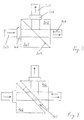
- Fig. 3 shows an embodiment of a dichroic beam splitter (206).
- This version comprises two 45 degree prisms (301 and 302), the inner surfaces (303) of which lie on one another. One of these surfaces preferably has an optically active coating.
- a GRIN lens (305) and a bandpass filter (306) are located at the entrance to the illumination beam path, before which the light source is in the module (A).
- a GRIN lens (307) forms the exit of the illumination beam path in front of which the object is located.
- the radiation emitted by the object is deflected into the detection beam path on the inside of the beam splitter (303).
- the emitted radiation falls through the edge filter (308) and a GRIN lens (309) onto the entrance slit of the microspectrometer in the assembly (C).
- Fig. 4 shows another embodiment of the dichroic beam splitter. Between the two 45 degree prisms (401 and 402) there is a plate (403) which carries a dichroic layer on one of its surfaces.
- the size of the figures does not indicate the significant differences in size between a miniaturized spectrometer according to the invention and a miniaturized spectrometer according to the prior art.
Landscapes
- Physics & Mathematics (AREA)
- Spectroscopy & Molecular Physics (AREA)
- General Physics & Mathematics (AREA)
- Chemical & Material Sciences (AREA)
- Analytical Chemistry (AREA)
- Optics & Photonics (AREA)
- Spectrometry And Color Measurement (AREA)
- Investigating, Analyzing Materials By Fluorescence Or Luminescence (AREA)
- Investigating Or Analysing Materials By Optical Means (AREA)
- Microscoopes, Condenser (AREA)
Applications Claiming Priority (2)
| Application Number | Priority Date | Filing Date | Title |
|---|---|---|---|
| DE102009021637 | 2009-05-16 | ||
| PCT/EP2010/056495 WO2010133485A1 (de) | 2009-05-16 | 2010-05-11 | Miniaturisiertes konfokales spektrometer |
Publications (2)
| Publication Number | Publication Date |
|---|---|
| EP2430415A1 EP2430415A1 (de) | 2012-03-21 |
| EP2430415B1 true EP2430415B1 (de) | 2020-05-27 |
Family
ID=42651140
Family Applications (1)
| Application Number | Title | Priority Date | Filing Date |
|---|---|---|---|
| EP10718218.0A Not-in-force EP2430415B1 (de) | 2009-05-16 | 2010-05-11 | Miniaturisiertes konfokales spektrometer |
Country Status (4)
| Country | Link |
|---|---|
| US (1) | US8525988B2 (enExample) |
| EP (1) | EP2430415B1 (enExample) |
| JP (1) | JP5628903B2 (enExample) |
| WO (1) | WO2010133485A1 (enExample) |
Families Citing this family (5)
| Publication number | Priority date | Publication date | Assignee | Title |
|---|---|---|---|---|
| WO2012109301A2 (en) | 2011-02-08 | 2012-08-16 | Battelle Memorial Institute | Line light source for raman or other spectroscopic system |
| US9110009B2 (en) * | 2011-03-21 | 2015-08-18 | University Of Central Florida Research Foundation, Inc. | Gradient index (GRIN)-based absorption spectroscopy apparatus, method, and applications |
| JP5966982B2 (ja) * | 2013-03-15 | 2016-08-10 | オムロン株式会社 | 共焦点計測装置 |
| TW202037888A (zh) * | 2018-11-26 | 2020-10-16 | 美商Tt電子公司 | 具有成形光源的光學編碼器系統 |
| EP4189341B1 (en) * | 2020-08-03 | 2026-02-25 | Siemens Healthcare Diagnostics, Inc. | Absorbance spectroscopy analyzer and method of use |
Family Cites Families (12)
| Publication number | Priority date | Publication date | Assignee | Title |
|---|---|---|---|---|
| JPH05231938A (ja) * | 1991-02-07 | 1993-09-07 | Res Dev Corp Of Japan | 高感度多波長分光装置 |
| JPH05281041A (ja) * | 1992-03-31 | 1993-10-29 | Omron Corp | 分光器 |
| WO1997005473A1 (en) * | 1995-08-01 | 1997-02-13 | Medispectra, Inc. | Optical microprobes and methods for spectral analysis of materials |
| US5813987A (en) * | 1995-08-01 | 1998-09-29 | Medispectra, Inc. | Spectral volume microprobe for analysis of materials |
| DE10010514B4 (de) * | 1999-03-08 | 2004-09-30 | Steag Microparts Gmbh | Optoelektronisches Mikrospektrometer |
| US6373567B1 (en) * | 1999-12-17 | 2002-04-16 | Micron Optical Systems | Dispersive near-IR Raman spectrometer |
| US20040155202A1 (en) * | 2002-11-21 | 2004-08-12 | Cdex, Inc. | Methods and apparatus for molecular species detection, inspection and classification using ultraviolet fluorescence |
| EP1740914A2 (en) * | 2004-04-30 | 2007-01-10 | Ahura Corporation | Method and apparatus for conducting raman spectroscopy |
| WO2006036434A2 (en) * | 2004-08-30 | 2006-04-06 | Ahura Corporation | Free-space coupling between laser, optical probe head, and spectrometer assemblies and other optical elements |
| DE102005043627B4 (de) * | 2005-09-13 | 2012-06-14 | Fraunhofer-Gesellschaft zur Förderung der angewandten Forschung e.V. | Optischer Sensor und Verfahren zur optischen Abstands- und/oder Farbmessung |
| DE102006046555B4 (de) * | 2006-09-28 | 2010-12-16 | Grintech Gmbh | Miniaturisiertes optisch abbildendes System mit hoher lateraler und axialer Auflösung |
| US7952706B2 (en) * | 2007-05-17 | 2011-05-31 | Prescient Medical, Inc. | Multi-channel fiber optic spectroscopy systems employing integrated optics modules |
-
2010
- 2010-05-11 WO PCT/EP2010/056495 patent/WO2010133485A1/de not_active Ceased
- 2010-05-11 JP JP2012510277A patent/JP5628903B2/ja not_active Expired - Fee Related
- 2010-05-11 EP EP10718218.0A patent/EP2430415B1/de not_active Not-in-force
- 2010-05-13 US US12/779,368 patent/US8525988B2/en not_active Expired - Fee Related
Non-Patent Citations (1)
| Title |
|---|
| None * |
Also Published As
| Publication number | Publication date |
|---|---|
| WO2010133485A1 (de) | 2010-11-25 |
| JP5628903B2 (ja) | 2014-11-19 |
| US20110037978A1 (en) | 2011-02-17 |
| WO2010133485A4 (de) | 2011-03-24 |
| JP2012526972A (ja) | 2012-11-01 |
| US8525988B2 (en) | 2013-09-03 |
| EP2430415A1 (de) | 2012-03-21 |
Similar Documents
| Publication | Publication Date | Title |
|---|---|---|
| DE112014000683B4 (de) | Faseroptische Sonde für die Fernspektroskopie | |
| DE10004191B4 (de) | Fluoreszenz-Scanmikroskop | |
| DE69737475T2 (de) | Mit makro- und mikroabtastobjektiven kompatibles fluoreszenzabbildungssystem | |
| DE102018124129A1 (de) | Mikroskopsystem und Verfahren zur mikroskopischen Abbildung mit einem solchen Mikroskopsystem | |
| DE102015207289A1 (de) | Partikelsensorvorrichtung | |
| EP2011092B1 (de) | Vorrichtung und verfahren zur optischen untersuchung von wertdokumenten | |
| DE102013224463B4 (de) | Vorrichtung zur Ermittlung von Fluoreszenzeigenschaften von Proben | |
| DE102015001032B4 (de) | Raman-Spektroskopie-Beleuchtungs- und Auslesesystem | |
| EP2652481A2 (de) | Vorrichtung zur photometrischen bzw. spektrometrischen untersuchung einer flüssigen probe | |
| WO2010133485A1 (de) | Miniaturisiertes konfokales spektrometer | |
| DE102005056663A1 (de) | Spektroskop vom Lichtleitfaser-Typ und damit ausgerüstetes Spektroskopsystem | |
| DE102018112253A1 (de) | Optische Anordnung für ein spektroskopisches bildgebendes Verfahren und spektroskopisches bildgebendes Verfahren | |
| EP3704473B1 (de) | Neuartiger sensor für die ramanspektroskopie | |
| EP3614130B1 (de) | Vorrichtung zur ermittlung optischer eigenschaften von proben | |
| WO1999003008A1 (de) | Vorrichtung zur optischen erfassung von proben | |
| WO2022063451A1 (de) | Vorrichtung und verfahren zur simultanen abbildung zweier objektebenen | |
| DE102006045624A1 (de) | Vorrichtung und Verfahren zur optischen Untersuchung von Wertdokumenten | |
| DE202013002752U1 (de) | Vorrichtung zur Ermittlung von Fluoreszenzeigenschaften von Proben | |
| DE102011082469B4 (de) | Spektrometer mit wenigstens einem Zerstreuungselement | |
| DE102018200646A1 (de) | System zum Messen optischer Eigenschaften von Proben | |
| DE20022966U1 (de) | Hochdurchsatzscreening-Vorrichtung zur optischen Erfassung von Proben | |
| DE102004030029B3 (de) | Transmissionsmessverfahren und deren Verwendung | |
| EP1889040B1 (de) | Messeinrichtung zur ramanspektrometrischen, nichtinvasiven glucosebestimmung | |
| DE102023000154B3 (de) | Vorrichtung für das Recycling diffuser elektromagnetischer Strahlung | |
| DE102022134248A1 (de) | Chromatisch konfokale Messeinrichtung |
Legal Events
| Date | Code | Title | Description |
|---|---|---|---|
| PUAI | Public reference made under article 153(3) epc to a published international application that has entered the european phase |
Free format text: ORIGINAL CODE: 0009012 |
|
| 17P | Request for examination filed |
Effective date: 20111216 |
|
| AK | Designated contracting states |
Kind code of ref document: A1 Designated state(s): AL AT BE BG CH CY CZ DE DK EE ES FI FR GB GR HR HU IE IS IT LI LT LU LV MC MK MT NL NO PL PT RO SE SI SK SM TR |
|
| DAX | Request for extension of the european patent (deleted) | ||
| 17Q | First examination report despatched |
Effective date: 20161017 |
|
| STAA | Information on the status of an ep patent application or granted ep patent |
Free format text: STATUS: EXAMINATION IS IN PROGRESS |
|
| GRAP | Despatch of communication of intention to grant a patent |
Free format text: ORIGINAL CODE: EPIDOSNIGR1 |
|
| STAA | Information on the status of an ep patent application or granted ep patent |
Free format text: STATUS: GRANT OF PATENT IS INTENDED |
|
| INTG | Intention to grant announced |
Effective date: 20191122 |
|
| GRAS | Grant fee paid |
Free format text: ORIGINAL CODE: EPIDOSNIGR3 |
|
| GRAA | (expected) grant |
Free format text: ORIGINAL CODE: 0009210 |
|
| STAA | Information on the status of an ep patent application or granted ep patent |
Free format text: STATUS: THE PATENT HAS BEEN GRANTED |
|
| AK | Designated contracting states |
Kind code of ref document: B1 Designated state(s): AL AT BE BG CH CY CZ DE DK EE ES FI FR GB GR HR HU IE IS IT LI LT LU LV MC MK MT NL NO PL PT RO SE SI SK SM TR |
|
| RAP1 | Party data changed (applicant data changed or rights of an application transferred) |
Owner name: INSION GMBH |
|
| REG | Reference to a national code |
Ref country code: GB Ref legal event code: FG4D Free format text: NOT ENGLISH |
|
| REG | Reference to a national code |
Ref country code: CH Ref legal event code: EP |
|
| REG | Reference to a national code |
Ref country code: AT Ref legal event code: REF Ref document number: 1275020 Country of ref document: AT Kind code of ref document: T Effective date: 20200615 |
|
| REG | Reference to a national code |
Ref country code: DE Ref legal event code: R096 Ref document number: 502010016650 Country of ref document: DE |
|
| REG | Reference to a national code |
Ref country code: LT Ref legal event code: MG4D |
|
| PG25 | Lapsed in a contracting state [announced via postgrant information from national office to epo] |
Ref country code: SE Free format text: LAPSE BECAUSE OF FAILURE TO SUBMIT A TRANSLATION OF THE DESCRIPTION OR TO PAY THE FEE WITHIN THE PRESCRIBED TIME-LIMIT Effective date: 20200527 Ref country code: LT Free format text: LAPSE BECAUSE OF FAILURE TO SUBMIT A TRANSLATION OF THE DESCRIPTION OR TO PAY THE FEE WITHIN THE PRESCRIBED TIME-LIMIT Effective date: 20200527 Ref country code: FI Free format text: LAPSE BECAUSE OF FAILURE TO SUBMIT A TRANSLATION OF THE DESCRIPTION OR TO PAY THE FEE WITHIN THE PRESCRIBED TIME-LIMIT Effective date: 20200527 Ref country code: GR Free format text: LAPSE BECAUSE OF FAILURE TO SUBMIT A TRANSLATION OF THE DESCRIPTION OR TO PAY THE FEE WITHIN THE PRESCRIBED TIME-LIMIT Effective date: 20200828 Ref country code: IS Free format text: LAPSE BECAUSE OF FAILURE TO SUBMIT A TRANSLATION OF THE DESCRIPTION OR TO PAY THE FEE WITHIN THE PRESCRIBED TIME-LIMIT Effective date: 20200927 Ref country code: NO Free format text: LAPSE BECAUSE OF FAILURE TO SUBMIT A TRANSLATION OF THE DESCRIPTION OR TO PAY THE FEE WITHIN THE PRESCRIBED TIME-LIMIT Effective date: 20200827 Ref country code: PT Free format text: LAPSE BECAUSE OF FAILURE TO SUBMIT A TRANSLATION OF THE DESCRIPTION OR TO PAY THE FEE WITHIN THE PRESCRIBED TIME-LIMIT Effective date: 20200928 |
|
| REG | Reference to a national code |
Ref country code: NL Ref legal event code: MP Effective date: 20200527 |
|
| PG25 | Lapsed in a contracting state [announced via postgrant information from national office to epo] |
Ref country code: LV Free format text: LAPSE BECAUSE OF FAILURE TO SUBMIT A TRANSLATION OF THE DESCRIPTION OR TO PAY THE FEE WITHIN THE PRESCRIBED TIME-LIMIT Effective date: 20200527 Ref country code: HR Free format text: LAPSE BECAUSE OF FAILURE TO SUBMIT A TRANSLATION OF THE DESCRIPTION OR TO PAY THE FEE WITHIN THE PRESCRIBED TIME-LIMIT Effective date: 20200527 Ref country code: BG Free format text: LAPSE BECAUSE OF FAILURE TO SUBMIT A TRANSLATION OF THE DESCRIPTION OR TO PAY THE FEE WITHIN THE PRESCRIBED TIME-LIMIT Effective date: 20200827 |
|
| PG25 | Lapsed in a contracting state [announced via postgrant information from national office to epo] |
Ref country code: NL Free format text: LAPSE BECAUSE OF FAILURE TO SUBMIT A TRANSLATION OF THE DESCRIPTION OR TO PAY THE FEE WITHIN THE PRESCRIBED TIME-LIMIT Effective date: 20200527 Ref country code: AL Free format text: LAPSE BECAUSE OF FAILURE TO SUBMIT A TRANSLATION OF THE DESCRIPTION OR TO PAY THE FEE WITHIN THE PRESCRIBED TIME-LIMIT Effective date: 20200527 |
|
| PG25 | Lapsed in a contracting state [announced via postgrant information from national office to epo] |
Ref country code: RO Free format text: LAPSE BECAUSE OF FAILURE TO SUBMIT A TRANSLATION OF THE DESCRIPTION OR TO PAY THE FEE WITHIN THE PRESCRIBED TIME-LIMIT Effective date: 20200527 Ref country code: CZ Free format text: LAPSE BECAUSE OF FAILURE TO SUBMIT A TRANSLATION OF THE DESCRIPTION OR TO PAY THE FEE WITHIN THE PRESCRIBED TIME-LIMIT Effective date: 20200527 Ref country code: ES Free format text: LAPSE BECAUSE OF FAILURE TO SUBMIT A TRANSLATION OF THE DESCRIPTION OR TO PAY THE FEE WITHIN THE PRESCRIBED TIME-LIMIT Effective date: 20200527 Ref country code: DK Free format text: LAPSE BECAUSE OF FAILURE TO SUBMIT A TRANSLATION OF THE DESCRIPTION OR TO PAY THE FEE WITHIN THE PRESCRIBED TIME-LIMIT Effective date: 20200527 Ref country code: SM Free format text: LAPSE BECAUSE OF FAILURE TO SUBMIT A TRANSLATION OF THE DESCRIPTION OR TO PAY THE FEE WITHIN THE PRESCRIBED TIME-LIMIT Effective date: 20200527 Ref country code: EE Free format text: LAPSE BECAUSE OF FAILURE TO SUBMIT A TRANSLATION OF THE DESCRIPTION OR TO PAY THE FEE WITHIN THE PRESCRIBED TIME-LIMIT Effective date: 20200527 Ref country code: IT Free format text: LAPSE BECAUSE OF FAILURE TO SUBMIT A TRANSLATION OF THE DESCRIPTION OR TO PAY THE FEE WITHIN THE PRESCRIBED TIME-LIMIT Effective date: 20200527 |
|
| PG25 | Lapsed in a contracting state [announced via postgrant information from national office to epo] |
Ref country code: SK Free format text: LAPSE BECAUSE OF FAILURE TO SUBMIT A TRANSLATION OF THE DESCRIPTION OR TO PAY THE FEE WITHIN THE PRESCRIBED TIME-LIMIT Effective date: 20200527 Ref country code: PL Free format text: LAPSE BECAUSE OF FAILURE TO SUBMIT A TRANSLATION OF THE DESCRIPTION OR TO PAY THE FEE WITHIN THE PRESCRIBED TIME-LIMIT Effective date: 20200527 |
|
| REG | Reference to a national code |
Ref country code: DE Ref legal event code: R097 Ref document number: 502010016650 Country of ref document: DE |
|
| PLBE | No opposition filed within time limit |
Free format text: ORIGINAL CODE: 0009261 |
|
| STAA | Information on the status of an ep patent application or granted ep patent |
Free format text: STATUS: NO OPPOSITION FILED WITHIN TIME LIMIT |
|
| 26N | No opposition filed |
Effective date: 20210302 |
|
| PG25 | Lapsed in a contracting state [announced via postgrant information from national office to epo] |
Ref country code: SI Free format text: LAPSE BECAUSE OF FAILURE TO SUBMIT A TRANSLATION OF THE DESCRIPTION OR TO PAY THE FEE WITHIN THE PRESCRIBED TIME-LIMIT Effective date: 20200527 |
|
| REG | Reference to a national code |
Ref country code: CH Ref legal event code: PL |
|
| PG25 | Lapsed in a contracting state [announced via postgrant information from national office to epo] |
Ref country code: CH Free format text: LAPSE BECAUSE OF NON-PAYMENT OF DUE FEES Effective date: 20210531 Ref country code: LI Free format text: LAPSE BECAUSE OF NON-PAYMENT OF DUE FEES Effective date: 20210531 Ref country code: MC Free format text: LAPSE BECAUSE OF FAILURE TO SUBMIT A TRANSLATION OF THE DESCRIPTION OR TO PAY THE FEE WITHIN THE PRESCRIBED TIME-LIMIT Effective date: 20200527 Ref country code: LU Free format text: LAPSE BECAUSE OF NON-PAYMENT OF DUE FEES Effective date: 20210511 |
|
| REG | Reference to a national code |
Ref country code: BE Ref legal event code: MM Effective date: 20210531 |
|
| PG25 | Lapsed in a contracting state [announced via postgrant information from national office to epo] |
Ref country code: IE Free format text: LAPSE BECAUSE OF NON-PAYMENT OF DUE FEES Effective date: 20210511 |
|
| PG25 | Lapsed in a contracting state [announced via postgrant information from national office to epo] |
Ref country code: FR Free format text: LAPSE BECAUSE OF NON-PAYMENT OF DUE FEES Effective date: 20210531 |
|
| REG | Reference to a national code |
Ref country code: AT Ref legal event code: MM01 Ref document number: 1275020 Country of ref document: AT Kind code of ref document: T Effective date: 20210511 |
|
| PG25 | Lapsed in a contracting state [announced via postgrant information from national office to epo] |
Ref country code: BE Free format text: LAPSE BECAUSE OF NON-PAYMENT OF DUE FEES Effective date: 20210531 |
|
| PG25 | Lapsed in a contracting state [announced via postgrant information from national office to epo] |
Ref country code: AT Free format text: LAPSE BECAUSE OF NON-PAYMENT OF DUE FEES Effective date: 20210511 |
|
| PG25 | Lapsed in a contracting state [announced via postgrant information from national office to epo] |
Ref country code: HU Free format text: LAPSE BECAUSE OF FAILURE TO SUBMIT A TRANSLATION OF THE DESCRIPTION OR TO PAY THE FEE WITHIN THE PRESCRIBED TIME-LIMIT; INVALID AB INITIO Effective date: 20100511 Ref country code: CY Free format text: LAPSE BECAUSE OF FAILURE TO SUBMIT A TRANSLATION OF THE DESCRIPTION OR TO PAY THE FEE WITHIN THE PRESCRIBED TIME-LIMIT Effective date: 20200527 |
|
| PG25 | Lapsed in a contracting state [announced via postgrant information from national office to epo] |
Ref country code: MK Free format text: LAPSE BECAUSE OF FAILURE TO SUBMIT A TRANSLATION OF THE DESCRIPTION OR TO PAY THE FEE WITHIN THE PRESCRIBED TIME-LIMIT Effective date: 20200527 |
|
| PG25 | Lapsed in a contracting state [announced via postgrant information from national office to epo] |
Ref country code: TR Free format text: LAPSE BECAUSE OF FAILURE TO SUBMIT A TRANSLATION OF THE DESCRIPTION OR TO PAY THE FEE WITHIN THE PRESCRIBED TIME-LIMIT Effective date: 20200527 |
|
| PGFP | Annual fee paid to national office [announced via postgrant information from national office to epo] |
Ref country code: GB Payment date: 20240522 Year of fee payment: 15 |
|
| PGFP | Annual fee paid to national office [announced via postgrant information from national office to epo] |
Ref country code: DE Payment date: 20240517 Year of fee payment: 15 |
|
| PG25 | Lapsed in a contracting state [announced via postgrant information from national office to epo] |
Ref country code: MT Free format text: LAPSE BECAUSE OF FAILURE TO SUBMIT A TRANSLATION OF THE DESCRIPTION OR TO PAY THE FEE WITHIN THE PRESCRIBED TIME-LIMIT Effective date: 20200527 |
|
| REG | Reference to a national code |
Ref country code: DE Ref legal event code: R119 Ref document number: 502010016650 Country of ref document: DE |
|
| GBPC | Gb: european patent ceased through non-payment of renewal fee |
Effective date: 20250511 |
|
| PG25 | Lapsed in a contracting state [announced via postgrant information from national office to epo] |
Ref country code: GB Free format text: LAPSE BECAUSE OF NON-PAYMENT OF DUE FEES Effective date: 20250511 |
|
| PG25 | Lapsed in a contracting state [announced via postgrant information from national office to epo] |
Ref country code: DE Free format text: LAPSE BECAUSE OF NON-PAYMENT OF DUE FEES Effective date: 20251202 |