EP2429424B1 - Rotational atherectomy device to improve abrading efficiency - Google Patents
Rotational atherectomy device to improve abrading efficiency Download PDFInfo
- Publication number
- EP2429424B1 EP2429424B1 EP10775219.8A EP10775219A EP2429424B1 EP 2429424 B1 EP2429424 B1 EP 2429424B1 EP 10775219 A EP10775219 A EP 10775219A EP 2429424 B1 EP2429424 B1 EP 2429424B1
- Authority
- EP
- European Patent Office
- Prior art keywords
- drive shaft
- abrading head
- mass
- diameter
- rotational
- Prior art date
- Legal status (The legal status is an assumption and is not a legal conclusion. Google has not performed a legal analysis and makes no representation as to the accuracy of the status listed.)
- Active
Links
- 210000001367 artery Anatomy 0.000 claims description 25
- 208000031481 Pathologic Constriction Diseases 0.000 claims description 20
- 230000036262 stenosis Effects 0.000 claims description 17
- 208000037804 stenosis Diseases 0.000 claims description 17
- 230000000284 resting effect Effects 0.000 claims description 11
- 210000001519 tissue Anatomy 0.000 description 48
- 238000005520 cutting process Methods 0.000 description 34
- 230000002966 stenotic effect Effects 0.000 description 22
- 238000000034 method Methods 0.000 description 19
- 239000000463 material Substances 0.000 description 12
- 230000003902 lesion Effects 0.000 description 11
- 239000003082 abrasive agent Substances 0.000 description 10
- 239000002245 particle Substances 0.000 description 10
- 238000013461 design Methods 0.000 description 8
- 230000000052 comparative effect Effects 0.000 description 7
- 238000002399 angioplasty Methods 0.000 description 6
- 229910003460 diamond Inorganic materials 0.000 description 6
- 239000010432 diamond Substances 0.000 description 6
- 230000033001 locomotion Effects 0.000 description 6
- 208000037260 Atherosclerotic Plaque Diseases 0.000 description 5
- 238000005299 abrasion Methods 0.000 description 5
- 238000010276 construction Methods 0.000 description 5
- 239000007787 solid Substances 0.000 description 5
- 239000011248 coating agent Substances 0.000 description 4
- 238000000576 coating method Methods 0.000 description 4
- 230000007246 mechanism Effects 0.000 description 4
- 238000002679 ablation Methods 0.000 description 3
- 239000008280 blood Substances 0.000 description 3
- 210000004369 blood Anatomy 0.000 description 3
- 230000008602 contraction Effects 0.000 description 3
- 238000001816 cooling Methods 0.000 description 3
- 210000004351 coronary vessel Anatomy 0.000 description 3
- 239000012530 fluid Substances 0.000 description 3
- 238000012986 modification Methods 0.000 description 3
- 230000004048 modification Effects 0.000 description 3
- 210000004872 soft tissue Anatomy 0.000 description 3
- 239000011230 binding agent Substances 0.000 description 2
- 230000001419 dependent effect Effects 0.000 description 2
- 239000000835 fiber Substances 0.000 description 2
- 230000037361 pathway Effects 0.000 description 2
- 239000000843 powder Substances 0.000 description 2
- 231100000241 scar Toxicity 0.000 description 2
- 206010002383 Angina Pectoris Diseases 0.000 description 1
- 201000001320 Atherosclerosis Diseases 0.000 description 1
- 229910052580 B4C Inorganic materials 0.000 description 1
- 206010020772 Hypertension Diseases 0.000 description 1
- VYPSYNLAJGMNEJ-UHFFFAOYSA-N Silicium dioxide Chemical compound O=[Si]=O VYPSYNLAJGMNEJ-UHFFFAOYSA-N 0.000 description 1
- FAPWRFPIFSIZLT-UHFFFAOYSA-M Sodium chloride Chemical compound [Na+].[Cl-] FAPWRFPIFSIZLT-UHFFFAOYSA-M 0.000 description 1
- 208000006011 Stroke Diseases 0.000 description 1
- NRTOMJZYCJJWKI-UHFFFAOYSA-N Titanium nitride Chemical compound [Ti]#N NRTOMJZYCJJWKI-UHFFFAOYSA-N 0.000 description 1
- 208000027418 Wounds and injury Diseases 0.000 description 1
- 230000000903 blocking effect Effects 0.000 description 1
- 230000017531 blood circulation Effects 0.000 description 1
- 210000004204 blood vessel Anatomy 0.000 description 1
- INAHAJYZKVIDIZ-UHFFFAOYSA-N boron carbide Chemical compound B12B3B4C32B41 INAHAJYZKVIDIZ-UHFFFAOYSA-N 0.000 description 1
- 229910010293 ceramic material Inorganic materials 0.000 description 1
- 230000006378 damage Effects 0.000 description 1
- 238000011161 development Methods 0.000 description 1
- 230000018109 developmental process Effects 0.000 description 1
- 239000000428 dust Substances 0.000 description 1
- 230000000694 effects Effects 0.000 description 1
- 238000009713 electroplating Methods 0.000 description 1
- 210000003038 endothelium Anatomy 0.000 description 1
- 238000005516 engineering process Methods 0.000 description 1
- 230000001815 facial effect Effects 0.000 description 1
- 238000011010 flushing procedure Methods 0.000 description 1
- 239000005350 fused silica glass Substances 0.000 description 1
- 230000004927 fusion Effects 0.000 description 1
- 238000003384 imaging method Methods 0.000 description 1
- 208000014674 injury Diseases 0.000 description 1
- 238000003780 insertion Methods 0.000 description 1
- 230000037431 insertion Effects 0.000 description 1
- 230000001050 lubricating effect Effects 0.000 description 1
- 238000012544 monitoring process Methods 0.000 description 1
- 208000010125 myocardial infarction Diseases 0.000 description 1
- TWNQGVIAIRXVLR-UHFFFAOYSA-N oxo(oxoalumanyloxy)alumane Chemical compound O=[Al]O[Al]=O TWNQGVIAIRXVLR-UHFFFAOYSA-N 0.000 description 1
- 230000008569 process Effects 0.000 description 1
- 238000009877 rendering Methods 0.000 description 1
- 230000008439 repair process Effects 0.000 description 1
- 208000037803 restenosis Diseases 0.000 description 1
- 238000012552 review Methods 0.000 description 1
- 238000007788 roughening Methods 0.000 description 1
- 239000011780 sodium chloride Substances 0.000 description 1
- 229910001220 stainless steel Inorganic materials 0.000 description 1
- 239000010935 stainless steel Substances 0.000 description 1
- 230000036346 tooth eruption Effects 0.000 description 1
- 230000007704 transition Effects 0.000 description 1
- 230000008733 trauma Effects 0.000 description 1
- WFKWXMTUELFFGS-UHFFFAOYSA-N tungsten Chemical compound [W] WFKWXMTUELFFGS-UHFFFAOYSA-N 0.000 description 1
- 239000010937 tungsten Substances 0.000 description 1
- 229910052721 tungsten Inorganic materials 0.000 description 1
- UONOETXJSWQNOL-UHFFFAOYSA-N tungsten carbide Chemical compound [W+]#[C-] UONOETXJSWQNOL-UHFFFAOYSA-N 0.000 description 1
Images


Classifications
-
- A—HUMAN NECESSITIES
- A61—MEDICAL OR VETERINARY SCIENCE; HYGIENE
- A61B—DIAGNOSIS; SURGERY; IDENTIFICATION
- A61B17/00—Surgical instruments, devices or methods, e.g. tourniquets
- A61B17/32—Surgical cutting instruments
- A61B17/3205—Excision instruments
- A61B17/3207—Atherectomy devices working by cutting or abrading; Similar devices specially adapted for non-vascular obstructions
- A61B17/320758—Atherectomy devices working by cutting or abrading; Similar devices specially adapted for non-vascular obstructions with a rotating cutting instrument, e.g. motor driven
-
- A—HUMAN NECESSITIES
- A61—MEDICAL OR VETERINARY SCIENCE; HYGIENE
- A61B—DIAGNOSIS; SURGERY; IDENTIFICATION
- A61B17/00—Surgical instruments, devices or methods, e.g. tourniquets
- A61B17/22—Implements for squeezing-off ulcers or the like on the inside of inner organs of the body; Implements for scraping-out cavities of body organs, e.g. bones; Calculus removers; Calculus smashing apparatus; Apparatus for removing obstructions in blood vessels, not otherwise provided for
- A61B2017/22038—Implements for squeezing-off ulcers or the like on the inside of inner organs of the body; Implements for scraping-out cavities of body organs, e.g. bones; Calculus removers; Calculus smashing apparatus; Apparatus for removing obstructions in blood vessels, not otherwise provided for with a guide wire
-
- A—HUMAN NECESSITIES
- A61—MEDICAL OR VETERINARY SCIENCE; HYGIENE
- A61B—DIAGNOSIS; SURGERY; IDENTIFICATION
- A61B17/00—Surgical instruments, devices or methods, e.g. tourniquets
- A61B17/32—Surgical cutting instruments
- A61B2017/320004—Surgical cutting instruments abrasive
-
- A—HUMAN NECESSITIES
- A61—MEDICAL OR VETERINARY SCIENCE; HYGIENE
- A61B—DIAGNOSIS; SURGERY; IDENTIFICATION
- A61B17/00—Surgical instruments, devices or methods, e.g. tourniquets
- A61B17/32—Surgical cutting instruments
- A61B17/3205—Excision instruments
- A61B17/3207—Atherectomy devices working by cutting or abrading; Similar devices specially adapted for non-vascular obstructions
- A61B17/320758—Atherectomy devices working by cutting or abrading; Similar devices specially adapted for non-vascular obstructions with a rotating cutting instrument, e.g. motor driven
- A61B2017/320766—Atherectomy devices working by cutting or abrading; Similar devices specially adapted for non-vascular obstructions with a rotating cutting instrument, e.g. motor driven eccentric
Definitions
- the invention relates to systems and devices for removing tissue from body passageways, such as removal of atherosclerotic plaque from arteries, utilizing a high-speed rotational atherectomy device.
- a variety of techniques and instruments have been developed for use in the removal or repair of tissue in arteries and similar body passageways.
- a frequent objective of such techniques and instruments is the removal of atherosclerotic plaques in a patient's arteries.
- Atherosclerosis is characterized by the buildup of fatty deposits (atheromas) in the intimal layer (under the endothelium) of a patient's blood vessels.
- drugs such as stenotic lesions or stenoses
- stenotic material the blocking material being referred to as stenotic material. If left untreated, such stenoses can cause angina, hypertension, myocardial infarction, strokes and the like.
- Rotational atherectomy procedures have become a common technique for removing such stenotic material. Such procedures are used most frequently to initiate the opening of calcified lesions in coronary arteries. Most often the rotational atherectomy procedure is not used alone, but is followed by a balloon angioplasty procedure, which, in turn, is very frequently followed by placement of a stent to assist in maintaining patentcy of the opened artery. For non-calcified lesions, balloon angioplasty most often is used alone to open the artery, and stents often are placed to maintain patentcy of the opened artery.
- a burr covered with an abrasive abrading material such as diamond particles is carried at the distal end of a flexible drive shaft.
- the burr is rotated at high speeds (typically, e.g., in the range of about 150,000-190,000 rpm) while it is advanced across the stenosis.
- high speeds typically, e.g., in the range of about 150,000-190,000 rpm
- the burr is removing stenotic tissue, however, it blocks blood flow.
- the artery will have been opened to a diameter equal to or only slightly larger than the maximum outer diameter of the burr. Frequently more than one size burr must be utilized to open an artery to the desired diameter.
- U.S. Pat. No. 5,314,438 discloses another atherectomy device having a drive shaft with a section of the drive shaft having an enlarged diameter, at least a segment of this enlarged surface being covered with an abrasive material to define an abrasive segment of the drive shaft. When rotated at high speeds, the abrasive segment is capable of removing stenotic tissue from an artery. Though this atherectomy device possesses certain advantages over the Auth device due to its flexibility, it also is capable only of opening an artery to a diameter about equal to the diameter of the enlarged abrading surface of the drive shaft since the device is not eccentric in nature.
- U.S. Pat. No. 6,494,890 discloses an atherectomy device having a drive shaft with an enlarged eccentric section, wherein at least a segment of this enlarged section is covered with an abrasive material. When rotated at high speeds, the abrasive segment is capable of removing stenotic tissue from an artery.
- the device is capable of opening an artery to a diameter that is larger than the resting diameter of the enlarged eccentric section due, in part, to the orbital rotational motion during high speed operation. Since the enlarged eccentric section comprises drive shaft wires that are not bound together, the enlarged eccentric section of the drive shaft may flex during placement within the stenosis or during high speed operation.
- This flexion allows for a larger diameter opening during high speed operation, but may also provide less control than desired over the diameter of the artery actually abraded.
- some stenotic tissue may block the passageway so completely that the Shturman device cannot be placed therethrough. Since Shturman requires that the enlarged eccentric section of the drive shaft be placed within the stenotic tissue to achieve abrasion, it will be less effective in cases where the enlarged eccentric section is prevented from moving into the stenosis.
- U.S. Pat No. 5,681 ,336 provides an eccentric tissue removing burr with a coating of abrasive particles secured to a portion of its outer surface by a suitable binding material.
- This construction is limited, however because, as Clement explains at Col. 3, lines 53-55, that the asymmetrical burr is rotated at "lower speeds than are used with high speed ablation devices, to compensate for heat or imbalance.” That is, given both the size and mass of the solid burr, it is infeasible to rotate the burr at the high speeds used during atherectomy procedures, i.e., 20,000- 200,000 rpm. Essentially, the center of mass offset from the rotational axis of the drive shaft would result in development of significant centrifugal force, exerting too much pressure on the wall of the artery and creating too much heat and excessively large particles.
- U.S. Patent Application Publication No. 2008/0306498 A1 provides a rotational atherectomy device having, in various embodiments, a flexible, elongated, rotatable drive shaft with at least one flexible eccentric enlarged abrading head attached thereto.
- the eccentric abrading head is not flexible or partially flexible.
- At least part of the eccentric enlarged cutting head has a tissue removing surface—typically an abrasive surface.
- the abrading head will be at least partially hollow.
- the eccentric nature of the enlarged cutting head causes the cutting head and drive shaft to rotate in such a fashion as to open the stenotic lesion to a diameter substantially larger than the outer diameter of the enlarged cutting head.
- the eccentric enlarged cutting head has a center of mass spaced radially from the rotational axis of the drive shaft, facilitating the ability of the device to open the stenotic lesion to a diameter substantially larger than the outer diameter of the enlarged cutting head when operated at high speeds.
- U.S. Patent No. 5,895,397 A discloses front-end and side-on intravascular catheters comprising an abrasive head contained substantially within a housing. Aspiration means and flushing means are connected to the region of grinding to remove dislodged debris.
- a preferred embodiment has the abrasive surface of a rotatable head comprised of diamond powder.
- Another preferred embodiment has an ultrasonic transducer affixed to the head to permit transluminal imaging of the site of occlusion.
- WO 2000/024321 A2 discloses an ablation burr having a body provided with an inner circumferential rim and an outer circumferential rim that are concentric and spaced longitudinally by a selected distance along the length of the burr.
- the outer circumferential rim has a generally smooth convex outer surface that reduces damage to a vessel wall or stent.
- a leading surface of the burr extends between the inner and outer circumferential rims in a substantially uniform, concave manner.
- An abrasive, for example, diamond grit, is provided on the leading surface. The burr is selectively rotated by a drive shaft, causing the abrasive leading surface of the burr to ablate unwanted deposits.
- U.S. Patent No. 5,308,354 A disclose a device for treating obstructions in vessels or small openings in the body, comprising a rotatable ablator tip which is guided to the obstruction in a reduced diameter configuration, expanded and rotated to remove the obstruction, and contracted to remove the device from the body.
- the variably expandable abrasive tip coil in one embodiment is actuated by piston means within the coil.
- a pair of collars is attached to the ends of the coil, and the piston effects relative longitudinal axial movement of the collars and the respective ends of the coil tip. When the ends of the coil tip are so moved, expansion and contraction of the diameter of the coil tip results.
- the expansion tip coil is actuated by an expandable and contractible bellows disposed within the coil.
- the expansion and contraction of the coil tip are effected by longitudinal axial movement of an internal coil attached to one end of the coil tip, within an outer coil attached to its other end.
- expansion and contraction of the coil tip are effected by an inflatable balloon disposed within the coil tip.
- the balloon expansion means enlarges preferably at the central portion of the coil to make a bulge.
- a combined atherectomy and balloon angioplasty device employing either a fixed or variable diameter rotatable abrasive burr, and an angioplasty balloon disposed proximal to the burr.
- U.S. Patent No. 5,728,129 A discloses a distal atherectomy catheter for removing obstructions, plaque, stenosis, occlusions, or the like from an artery or coronary vessel.
- the catheter comprises a flexible, hollow catheter tube.
- a cutting element is located within a cylindrical housing mounted at the distal end of the catheter tube.
- the cutting element is connected to a hollow, flexible drive shaft concentrically located within the catheter tube.
- the cutting element housing includes a side opening window or port providing access to the interior of the housing.
- An idler shaft journaled about the drive shaft provides a non-rotating surface adjacent the cutting element.
- An annular return passage is defined between the catheter tube and the flexible drive shaft providing a discharge passage communicating with external aspirating means for collection of cuttings removed by the cutting element from the artery or coronary vessel.
- a guide wire may extend through the catheter tube and cutting element for guiding the catheter to the occluded site in a vessel.
- the drive cable is connected to a drive motor housed within a handle housing.
- the catheter tube and cutter housing are enclosed within a sheath extending from the distal end of the catheter to the handle housing.
- WO 2001/054595 A1 discloses an atherectomy device for removing plaque from the interior of a lumen upon travel of the device therethrough, comprising: a rotatable head having nose, central and tail portions; said head having a plurality of longitudinally extending cutting grooves formed therein commencing proximate juncture of said circular nose portion and said central portion and extending rearwardly therefrom.
- U.S. Patent Application Publication No. 2005/0123363 A1 discloses a routing tool for cutting material and an associated apparatus and method.
- the tool includes a substantially cylindrical shaft member having a shank portion and a cutting portion.
- the cutting portion includes a plurality of cutting teeth disposed peripherally about a first helix and an intersecting second helix.
- Each cutting tooth defines a first cutting clearance on a first cutting edge and a first clearance on a first non-cutting edge.
- the cutting tooth defines a second cutting clearance on a second cutting edge and a second clearance on a second non-cutting edge.
- a flat extends on each cutting tooth resulting in a circular land on an outside diameter of the cutting portion.
- U.S. Patent Application Publication No. 2009/0105736 A1 provides a rotational atherectomy device having a flexible, elongated, rotatable drive shaft with an abrasive section comprising an enlarged diameter section of the drive shaft or, alternatively, a solid abrasive crown which may be attached to the drive shaft.
- the device further comprises a proximal and/or a distal counterweight attached to the drive shaft, spaced from the abrasive section wherein each counterweight has its center of mass offset from the longitudinal axis of the drive shaft to stimulate orbital motion by the abrasive section.
- the orbiting nature of the abrasive section causes such section to rotate as to open the stenotic lesion to a diameter substantially larger than the resting outer diameter of the abrasive section.
- current tissue-removing elements comprise continuous abrasive surfaces in e.g., either a symmetrical or asymmetrical elliptical or spherical configuration. It is known that a hydraulic wedge forms in some cases between the current tissue-removing element design and the arterial wall and plaque, reducing the contact between the abrasive and the plaque and, as a result, reducing the efficacy of the procedure. Moreover, the relatively smooth abrasive face of current designs does not maximize abrading and/or cutting efficacy. Finally, the known relatively smooth tissue-removing element designs result in atherectomy procedures of unpredictable length when working with soft plaque and/or non-calcified lesions and/or diffuse lesions.
- an atherectomy device having a tissue-removing element with facial grooves and comprising additional cutting edges and features as well as providing a mechanism for breaking the hydraulic wedge that exists between the abrasive and the arterial wall and plaque.
- a tissue-removing element that is more effective with soft plaque and/or non-calcified and/or diffuse lesions, thereby increasing the predictability of procedure outcome and length when working with such blockages.
- the invention is as defined in independent claim 1, with preferred embodiments defined in the dependent claims.
- the invention provides a rotational atherectomy system and device having, in various embodiments, a flexible, elongated, rotatable drive shaft with at least one eccentric abrading head attached thereto, the drive shaft having a rotational axis.
- the at least one eccentric abrading head having a mass, the abrading head mass including a distribution, and a nominal resting diameter and including proximal, intermediate and distal portions, wherein the proximal portion includes a proximal outer surface, the intermediate portion includes an intermediate outer surface, the intermediate portion having a mass located therein, and the distal portion includes a distal outer surface, the proximal outer surface having diameters that increase distally, the distal outer surface having diameters that decrease distally, and the intermediate outer surface being cylindrical, wherein at least the intermediate outer surface includes at least one axial groove and at least one non-grooved section, wherein the at least one non-grooved section includes abrasive coated thereon, wherein the at least one groove includes abrasive coated thereon, and wherein the abrading head defines a drive shaft lumen therethrough, wherein the drive shaft at least partially traverses the drive shaft lumen, the at least one eccentric abrading head further including a geometric center location radi
- the eccentric enlarged abrading head with the center of mass spaced radially from the rotational axis of the drive shaft, facilitating the ability of the device to open the stenotic lesion to a diameter substantially larger than the outer diameter of the enlarged abrading head when operated at high speeds.
- the groove(s) provide improved efficacy in the abrasion of non-calcified and/or soft tissue as well as provide a means for breaking the hydraulic wedge between the abrading head and the stenotic tissue.
- An object of the invention is to provide a high-speed rotational atherectomy device having at least one eccentric abrading head operatively connected to a rotatable drive shaft and having a resting diameter smaller than its high-speed rotational diameter and comprising at least one groove along the tissue removing surface.
- Another object of the invention is to provide a high-speed rotational atherectomy device having at least one eccentric abrading head comprising at least one groove along the tissue removing surface of the abrading head for facilitating breaking the hydraulic wedge between the tissue removing surface and the stenotic tissue.
- Another object of the invention is to provide a high-speed rotational atherectomy device having at least one eccentric abrading head comprising at least one groove along the tissue removing surface of the abrading head for improving the efficacy in abrading non-calcified and/or soft stenotic tissue.
- Another object of the invention is to provide a high-speed rotational atherectomy device having at least one eccentric abrading head comprising at least one radial and/or axial groove along the tissue removing surface of the abrading head.
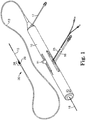
- FIG. 1 illustrates one embodiment of a rotational atherectomy device according to the present invention.
- the device includes a handle portion 10, an elongated, flexible drive shaft 20 having an eccentric enlarged abrading head 28, the abrading head having at least one groove 29, and an elongated catheter 13 extending distally from the handle portion 10.
- the drive shaft 20 is constructed from helically coiled wire as is known in the art and the abrading head 28 is fixedly attached thereto.
- Grooves 29 are illustrated along the tissue-removing surface of abrading head 28. In the illustrated embodiment grooves 29 are axial, though other arrangements of the grooves 29 are within the scope of the present invention and are discussed further herein.
- the catheter 13 has a lumen in which most of the length of the drive shaft 20 is disposed, except for the enlarged abrading head 28 and a short section distal to the enlarged abrading head 28.
- the drive shaft 20 also contains an inner lumen, permitting the drive shaft 20 to be advanced and rotated over a guide wire 15.
- a fluid supply line 17 may be provided for introducing a cooling and lubricating solution (typically saline or another biocompatible fluid) into the catheter 13.
- the handle 10 desirably contains a turbine (or similar rotational drive mechanism) for rotating the drive shaft 20 at high speeds.
- the handle 10 typically may be connected to a power source, such as compressed air delivered through a tube 16.
- a pair of fiber optic cables 25, alternatively a single fiber optic cable may be used, may also be provided for monitoring the speed of rotation of the turbine and drive shaft 20 (details regarding such handles and associated instrumentation are well known in the industry, and are described, e.g., in U.S. Pat. No. 5,314,407, issued to Auth ).
- the handle 10 also desirably includes a control knob 1 1 for advancing and retracting the turbine and drive shaft 20 with respect to the catheter 13 and the body of the handle.
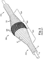
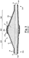
- FIGS. 2 and 3 illustrate details of a prior art abrading head comprising an eccentric enlarged diameter abrading section 28A of a drive shaft 20A.
- the drive shaft 20A comprises one or more helically wound wires 18 which define a guide wire lumen 19A and a hollow cavity 25A within the enlarged abrading section 28A. Except for the guide wire 15 traversing the hollow cavity 25A, the hollow cavity 25A is substantially empty.
- the eccentric enlarged diameter abrading section 28A includes, relative to the location of the stenosis, proximal 30A, intermediate 35A and distal 40A portions.
- Wire turns 33 of the proximal portion 30A of the eccentric enlarged diameter section 28A preferably have diameters that progressively increase distally at a generally constant rate, thereby forming generally the shape of a cone.
- Wire turns 41 of the distal portion 40A preferably have diameters that progressively decrease distally at a generally constant rate, thereby forming generally the shape of a cone.
- Wire turns 36 of the intermediate portion 35A are provided with gradually changing diameters to provide a generally convex outer surface which is shaped to provide a smooth transition between the proximal and distal conical portions of the enlarged eccentric diameter section 28A of the drive shaft 20A.
- At least part of the eccentric enlarged diameter abrading section of the drive shaft 28A (preferably the intermediate portion 35A) comprises an external surface capable of removing tissue.
- a tissue removing surface 37 comprising a coating of an abrasive material 24A to define a tissue removing segment of the drive shaft 20A is shown attached directly to the wire turns of the drive shaft 20A by a suitable binder 26A.
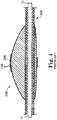
- Fig 4 illustrates another prior art rotational atherectomy device which, in contrast with the substantially hollow device of Figs 2 and 3 , employs a solid asymmetrical abrasive burr 28B attached to a flexible drive shaft 20B, rotated over a guide wire 15 such as provided by U.S. Pat No. 5,681 ,336 to Clement .
- the eccentric tissue removing burr 28B has a coating of abrasive particles 24B secured to a portion of its outer surface by a suitable binding material 26B. This construction has limited utility, however because, as Clement explains at Col.
- the asymmetrical burr 28B must be rotated at "lower speeds than are used with high speed ablation devices, to compensate for heat or imbalance.” That is, given both the size and mass of the solid burr-type construction, it is infeasible to rotate such a burr at the high speeds used during atherectomy procedures, i.e., 20,000-200,000 rpm. Further, the abrasive section of this prior art device is relatively smooth, i.e., grooves are not present. As a result, this prior art device will be less than efficient when dealing with non-calcified and/or soft stenoses.
- the abrading head 28 comprises three sections: a cone- shaped distal section 30, a cylindrical-shaped intermediate section 35 and a cone- shaped proximal section 40.
- the proximal section 40 comprises a proximal outer surface
- the intermediate section comprises an intermediate outer surface
- the distal section 30 comprises a distal outer surface, the proximal outer surface having diameters that increase distally, the distal outer surface having diameters that decrease distally, and the intermediate outer surface being cylindrical.
- the intermediate section 35 comprises axial grooves 29.
- the present invention may comprise at least one such groove 29 disposed on the outer surface of at least the intermediate section 35.
- the outer surface of the intermediate section 35 further comprises non-grooved sections 31 between each groove 29.
- the embodiment comprises the at least one groove 29 located within the intermediate section 35, though the distal 30 and/or proximal 40 sections may comprise at least one groove 29 in alternate embodiments.
- the groove(s) 29 aid in the abrading, cutting and/or grinding of soft and/or non-calcified tissue or plaque from the vessel.
- the groove(s) 29 provide a mechanism disrupting or breaking the hydraulic wedge that typically results when a relatively smooth surfaced abrasive head rotates at high speed against the stenosis and/or arterial wall.
- the groove(s) 29 thus provides increased contact between the abrasive head 28 and the stenosis and, as a result, improves abrasive efficiency and efficacy.
- the groove(s) 29 provide a mechanism for abrading, cutting and/or grinding non-calcified and/or soft tissue by allowing the soft tissue to expand slightly into the groove, rendering this tissue more amenable to abrasion, cutting and/or grinding, i.e., removal by the rapidly rotating abrading head 28. This is similar to the use of multiple, parallel blades on a razor; a hair portion left behind by a first blade may "spring up" and be cut by one or more subsequent blades.
- the groove(s) 29 provide a pathway allowing abraded, removed material to flow away from the cutting area.
- the number of groove(s) 29 may be one or more, i.e., two, three, four, five, six or any suitable number.
- the abrading head 28 may further comprise at least one tissue removing surface disposed on the external surface(s) of the intermediate section 35, the distal section 30 and/or the proximal section 40 to facilitate abrasion of the stenosis during high speed rotation.
- the tissue removing surface may comprise a coating of an abrasive material 24 bound to the external surface(s) of the intermediate section 35, the distal section 30 and/or the proximal section 40 of abrading head 28.
- the abrasive material 24 is bound to the non-grooved sections 31 located between each groove 29.
- the abrasive material 24 is further bound within the groove(s) 29.
- the at least one groove 29 may be curved in profile or may have a non-curvilinear profile, i.e., a flute shape as is well known to the skilled artisan.
- the abrasive material may be any suitable material, such as diamond powder, fused silica, titanium nitride, tungsten carbide, aluminum oxide, boron carbide, or other ceramic materials.
- the abrasive material is comprised of diamond chips (or diamond dust particles) attached directly to the tissue removing surface(s) by a suitable binder. Such attachment may be achieved using well known techniques, such as conventional electroplating or fusion technologies (see, e.g., U.S. Pat. No. 4,018,576 ).
- the external tissue removing surface may comprise mechanically or chemically roughening the external surface(s) of the intermediate portion 35, the distal portion 40 and/or the proximal portion 30 to provide a suitable abrasive tissue removing surface.
- the external surface may be etched or cut (e.g., with a laser) to provide small but effective abrading surfaces. Other similar techniques may also be utilized to provide a suitable tissue removing surface.
- an at least partially enclosed lumen or slot 23 may be provided longitudinally through the enlarged abrading head 28 along the rotational axis 21 of the drive shaft 20 for securing the abrading head 28 to the drive shaft 20 in a manner well known to those skilled in the art.
- a hollowed section 2 is defined by the eccentric abrading head 28 and is provided to lessen the mass of the abrading head 28 to facilitate atraumatic abrasion, and improve predictability of control of the orbital pathway of the abrading head 28 during high speed, i.e., 20,000 to 200,000 rpm, operation, and/or to increase the eccentricity and asymmetry of the abrading head 28 through designed manipulation of the center of mass of the abrading head 28 relative to the rotational axis of the drive shaft as will be discussed further infra, thereby increasing the rotational diameter of the abrading head 28.
- Alternate examples of abrading head, not forming part of the present invention, may not comprise the hollowed section 2. Hollowed section 2 is not required to achieve eccentricity of the abrading head 28, comprising a center of mass that is offset from the rotational axis of the drive shaft 20.
- abrading head 28 may be fixedly attached to the drive shaft 20, wherein the drive shaft comprises one single unit.
- the drive shaft 20 may comprise two separate pieces, wherein the enlarged eccentric abrading head 28 is fixedly attached to both drive shaft 20 pieces, with a gap therebetween.
- This two-piece drive shaft construction technique may, in combination with hollowed section 2, allow further manipulation of the placement of the center of mass of the abrading head 28.
- the size and shape of the hollowed section 2, when present, may be modified to optimize the orbital rotational path of the abrading head 28 for particularly desirable rotational speeds.
- At least one eccentric abrading head 28 may be attached to the drive shaft 20.
- One, two, three or more abrading heads 28 may be employed, each with differing geometries, profiles, number and placement of groove(s) 29, abrasive placement and other functional characteristics in order to maximize efficiency and efficacy.
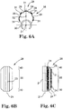
- Figs 5 and 6A-6C illustrates the distal 30 and proximal 40 sections being of symmetrical shape and length as well as equivalent slopes in the distal 30 and proximal sections leading up to the intermediate section 35.
- Alternate embodiments may increase the length of either the proximal portion 30 or the distal portion 40, to create an asymmetrical profile.
- the symmetry of the abrading head 28 as illustrated in Figs 5 and 6A-6C is preferred, though alternate embodiments may comprise a larger or smaller degree of slope in distal 30 and/or proximal 40 sections.
- the distal 30 and/or proximal 40 sections and/or the intermediate section 35 may have a longer or shorter length. Each such combination is within the scope of the present invention.
- the eccentric abrading head 28 of the present invention comprises a center of mass 32 that is spaced geometrically and radially away from the longitudinal rotational axis 21 of the drive shaft 20. Offsetting the center of mass 32 from the drive shaft's axis of rotation 21 provides the enlarged abrading head 28 with an eccentricity that permits it to open an artery to a diameter substantially larger during high-speed rotation than the nominal diameter of the enlarged eccentric abrading head 28. In accordance with the present invention the opened diameter is at least twice as large as the nominal resting diameter of the enlarged eccentric abrading head 28. Additionally, such offsetting of the center of mass 32 may be enhanced or manipulated by varying the amount of mass and location of mass in the intermediate section 35 by, e.g., including the hollowed section 2 and varying its size, location and shape within the intermediate section 35.
- the words “eccentric” and “eccentricity” are defined and used herein to refer to either a difference in location between the geometric center of the enlarged abrading head 28 and the rotational axis 21 of the drive shaft 20, or to a difference in location between the center of mass 32 of the enlarged abrading head 28 and the rotational axis 21 of the drive shaft 20. Either such difference, at the proper rotational speeds, will enable the eccentric enlarged abrading head 28 to open a stenosis to a diameter substantially greater than the nominal diameter of the eccentric enlarged abrading head 28.
- the abrading head 28 of the rotational atherectomy device of the invention may be constructed of stainless steel, tungsten or similar material.
- the abrading head 28 may be a single piece unitary construction or, alternatively, may be an assembly of two or more abrading head components fitted and fixed together to achieve the objects of the present invention.
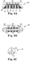
- FIGS 7A-7D another embodiment of the abrading head 28 is illustrated.
- This embodiment illustrates, inter alia, the variation of the slope of the distal 30 and proximal 40 sections as compared with the embodiment in Figs 6A-6C .
- the embodiment in Figs 7A-7D comprises a smaller degree of slope in the distal 30 and proximal 30 sections relative to the intermediate section 35. This smaller degree of slope may contribute to longer distal 30 and proximal 40 sections in comparison with the embodiment of Figs 6A-6C .
- axial grooves 29 are provided on the intermediate section 35 and not on the distal 30 and/or proximal 40 sections, though addition of groove(s) 29 thereon is within the scope of this invention.
- Abrasive material 24 is bound to the non-grooved sections 31 located between each groove 29 and the abrasive material 24 being further bound within the groove(s) 29.
- the center of mass 32 of the abrading head 28 is offset from the rotational axis 21 of the drive shaft 20 in this embodiment as well as in all others disclosed herein.
- the embodiment illustrated comprises relatively short distal 40 and proximal 30 sections in combination with a relatively long intermediate section 35 as compared with the embodiments discussed supra. This results in a relatively flattened configuration wherein the center of mass 32 is relatively close to the rotational axis 21 of the drive shaft 20 in comparison with that of the prior-discussed embodiments.
- this exemplary embodiment illustrates several of the variables that may be manipulated to maximize the efficacy of the design.
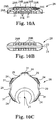
- Figs 9A-9C and 10A-10C Comparative examples that show some aspects of the abrading head 28 are shown in Figs 9A-9C and 10A-10C , but do not form part of the present invention. Specifically, in Figs 9A-9C , the groove(s) 29 are radial rather than axial with abrasive 24 in the non-grooved regions 31 defined between adjacent grooves 29.
- radial grooves 29R and axial grooves 29A intersect to form discrete non-grooved regions 31 with abrasive 24 thereon.
- These discrete non-grooved regions 31 may comprise, and are defined by, four edges 31 E to facilitate cutting of stenotic tissue, the sharp edges 31 E formed and defined by the intersection of radial grooves 29R with the axial grooves 29A on the intermediate section 35.
- the distal 30 and/or proximal 40 sections may comprise grooves 29 as well.
- the extent to which a stenosis in an artery can be opened to a diameter larger than the nominal diameter of the enlarged abrading head 28 of the present invention depends on several parameters, including the shape of the enlarged abrading head 28, the mass of the eccentric enlarged abrading head 28, the distribution of that mass within the abrading head 28 and, therefore, the location of the center of mass 32 within the abrading head 28 with respect to the rotational axis 21 of the drive shaft 20, and the speed of rotation of the drive shaft 20 and abrading head 28 mounted thereon.
- the speed of rotation of the abrading head 28 is a significant factor in determining the centrifugal force with which the tissue removing surface of the enlarged abrading head 28 is pressed against the stenotic tissue, thereby permitting the operator to control the rate of tissue removal.
- Control of the rotational speed also allows, to some extent, control over the maximum diameter to which the device will open a stenosis.
- Applicants have also found that the ability to reliably control the force with which the tissue removing surface is pressed against the stenotic tissue not only permits the operator to better control the rate of tissue removal but also provides better control of the size of the particles being removed.
- the abrading head 28 of the present invention may comprise more mass than typical prior art high speed atherectomy abrading devices.
- a larger orbit i.e., a larger rotational diameter
- using a smaller abrading head will allow for greater ease of access and less trauma during insertion.
- the eccentric enlarged abrading head 28 is repeatedly moved distally and proximally through the stenosis.
- the rotational speed of the device he or she is able to control the force with which the tissue removal surface is pressed against the stenotic tissue, thereby being able to better control the speed of the plaque removal as well as the particle size of tissue removed.
- the stenosis is being opened to a diameter larger than the nominal diameter of the enlarged abrading head 28, the cooling solution and the blood are able to constantly flow around the enlarged abrading head.
- the groove(s) 29, 29R and/or 29A provide a channel(s) for fluid flow around the abrading head 28.
- Such constant flow of blood and cooling solution constantly flushes away removed tissue particles, thus providing uniform release of removed particles, once the abrading head 28 has passed through the lesion once.
- the eccentric enlarged abrading head 28 may comprise a maximum cross-sectional diameter ranging between about 1.0 mm to about 3.0 mm.
- the eccentric enlarged abrading head may comprise cross-sectional diameters including, but not limited to: 1.0 mm, 1.25 mm, 1.50 mm, 1.75 mm, 2.0 mm, 2.25 mm, 2.50 mm, 2.75 mm, and 3.0 mm.
- cross-sectional diameters including, but not limited to: 1.0 mm, 1.25 mm, 1.50 mm, 1.75 mm, 2.0 mm, 2.25 mm, 2.50 mm, 2.75 mm, and 3.0 mm.
- the eccentricity of the enlarged abrading head 28 is dependent on a number of parameters, applicants have found that the following design parameters may be considered regarding the distance between the rotational axis 21 of the drive shaft 20 and the geometric center of a face of a transverse cross-section, taken at a position of maximum cross-sectional diameter of the eccentric enlarged abrading head: for a device having an eccentric enlarged abrading head with a maximum cross-sectional diameter between about 1.0 mm and about 1.5 mm, desirably the geometric center should be spaced away from the rotational axis of the drive shaft by a distance of at least about 0.02 mm, and preferably by a distance of at least about 0.035 mm; for a device having an eccentric enlarged abrading head with a maximum cross-sectional diameter between about 1.5 mm and about 1.75 mm, desirably the geometric center should be spaced away from the rotational axis of the drive shaft by a distance of at least about 0.05 mm, preferably by a
- Design parameters can also be based on the location of the center of mass.
- the center of mass should be spaced away from the rotational axis of the drive shaft by a distance of at least about 0.013 mm, and preferably by a distance of at least about 0.02 mm;
- the center of mass should be spaced away from the rotational axis of the drive shaft by a distance of at least about 0.03 mm, and preferably by a distance of at least about 0.05 mm;
- the center of mass should be spaced away from the rotational axis of the drive shaft by a distance of at least about 0.03 mm, and preferably by a distance of at least about 0.05 mm;
- the center of mass should be spaced away from the rotational axis of the drive shaft by a distance
- the design parameters are selected so that the enlarged abrading head 28 is sufficiently eccentric that, when rotated over a stationary guide wire 15 (held sufficiently taut so as to preclude any substantial movement of the guide wire) at a rotational speed greater than about 20,000 rpm, at least a portion of its tissue removing surface 37 may rotate through a path (whether or not such path is perfectly regular or circular) having a diameter larger than the maximum nominal diameter of the eccentric enlarged abrading head 28.
- At least a portion of the abrading head 28 may rotate through a path having a diameter at least about 10% larger than the maximum nominal diameter of the eccentric enlarged abrading head 28, preferably at least about 15% larger than the maximum nominal diameter of the eccentric enlarged abrading head 28, and most preferably at least about 20% larger than the maximum nominal diameter of the eccentric enlarged abrading head 28.
- At least a portion of the abrading head 28 may rotate through a path having a diameter at least about 20% larger than the maximum nominal diameter of the eccentric enlarged abrading head 28, preferably at least about 25% larger than the maximum nominal diameter of the eccentric enlarged abrading head 28, and most preferably at least about 30%larger than the maximum nominal diameter of the eccentric enlarged abrading head 28.
- At least a portion of the abrading head 28 may rotate through a path having a diameter at least about 30% larger than the maximum nominal diameter of the eccentric enlarged abrading head 28, and preferably at least about 40% larger than the maximum nominal diameter of the eccentric enlarged abrading head 28.
- design parameters are selected so that the enlarged abrading head 28 is sufficiently eccentric that, when rotated over a stationary guide wire 15 at a speed between about 20,000 rpm and about 200,000 rpm, at least a portion of its abrading head 28 rotates through a path (whether or not such path is perfectly regular or circular) with a maximum diameter that is substantially larger than the maximum nominal diameter of the resting eccentric enlarged abrading head 28.
- the present invention is capable of defining a substantially orbital path with a maximum diameter that is incrementally between at least about 50% and about 400% larger than the maximum nominal diameter of the resting eccentric enlarged abrading head 28.
- such orbital path comprises a maximum diameter that is between at least about 200% and about 400% larger than the maximum nominal diameter of the resting eccentric enlarged abrading head 28.
Description
- The invention relates to systems and devices for removing tissue from body passageways, such as removal of atherosclerotic plaque from arteries, utilizing a high-speed rotational atherectomy device.
- A variety of techniques and instruments have been developed for use in the removal or repair of tissue in arteries and similar body passageways. A frequent objective of such techniques and instruments is the removal of atherosclerotic plaques in a patient's arteries. Atherosclerosis is characterized by the buildup of fatty deposits (atheromas) in the intimal layer (under the endothelium) of a patient's blood vessels. Very often over time, what initially is deposited as relatively soft, cholesterol- rich atheromatous material hardens into a calcified atherosclerotic plaque. Such atheromas restrict the flow of blood, and therefore often are referred to as stenotic lesions or stenoses, the blocking material being referred to as stenotic material. If left untreated, such stenoses can cause angina, hypertension, myocardial infarction, strokes and the like.
- Rotational atherectomy procedures have become a common technique for removing such stenotic material. Such procedures are used most frequently to initiate the opening of calcified lesions in coronary arteries. Most often the rotational atherectomy procedure is not used alone, but is followed by a balloon angioplasty procedure, which, in turn, is very frequently followed by placement of a stent to assist in maintaining patentcy of the opened artery. For non-calcified lesions, balloon angioplasty most often is used alone to open the artery, and stents often are placed to maintain patentcy of the opened artery. Studies have shown, however, that a significant percentage of patients who have undergone balloon angioplasty and had a stent placed in an artery experience stent restenosis-i.e., blockage of the stent which most frequently develops over a period of time as a result of excessive growth of scar tissue within the stent. In such situations an atherectomy procedure is the preferred procedure to remove the excessive scar tissue from the stent (balloon angioplasty being not very effective within the stent), thereby restoring the patentcy of the artery.
- Several kinds of rotational atherectomy devices have been developed for attempting to remove stenotic material. In one type of device, such as that shown in
U.S. Pat. No. 4,990,134 (Auth ), a burr covered with an abrasive abrading material such as diamond particles is carried at the distal end of a flexible drive shaft. The burr is rotated at high speeds (typically, e.g., in the range of about 150,000-190,000 rpm) while it is advanced across the stenosis. As the burr is removing stenotic tissue, however, it blocks blood flow. Once the burr has been advanced across the stenosis, the artery will have been opened to a diameter equal to or only slightly larger than the maximum outer diameter of the burr. Frequently more than one size burr must be utilized to open an artery to the desired diameter. -
U.S. Pat. No. 5,314,438 (Shturman ) discloses another atherectomy device having a drive shaft with a section of the drive shaft having an enlarged diameter, at least a segment of this enlarged surface being covered with an abrasive material to define an abrasive segment of the drive shaft. When rotated at high speeds, the abrasive segment is capable of removing stenotic tissue from an artery. Though this atherectomy device possesses certain advantages over the Auth device due to its flexibility, it also is capable only of opening an artery to a diameter about equal to the diameter of the enlarged abrading surface of the drive shaft since the device is not eccentric in nature. -
U.S. Pat. No. 6,494,890 (Shturman ) discloses an atherectomy device having a drive shaft with an enlarged eccentric section, wherein at least a segment of this enlarged section is covered with an abrasive material. When rotated at high speeds, the abrasive segment is capable of removing stenotic tissue from an artery. The device is capable of opening an artery to a diameter that is larger than the resting diameter of the enlarged eccentric section due, in part, to the orbital rotational motion during high speed operation. Since the enlarged eccentric section comprises drive shaft wires that are not bound together, the enlarged eccentric section of the drive shaft may flex during placement within the stenosis or during high speed operation. This flexion allows for a larger diameter opening during high speed operation, but may also provide less control than desired over the diameter of the artery actually abraded. In addition, some stenotic tissue may block the passageway so completely that the Shturman device cannot be placed therethrough. Since Shturman requires that the enlarged eccentric section of the drive shaft be placed within the stenotic tissue to achieve abrasion, it will be less effective in cases where the enlarged eccentric section is prevented from moving into the stenosis. -
U.S. Pat No. 5,681 ,336 (Clement ) provides an eccentric tissue removing burr with a coating of abrasive particles secured to a portion of its outer surface by a suitable binding material. This construction is limited, however because, as Clement explains at Col. 3, lines 53-55, that the asymmetrical burr is rotated at "lower speeds than are used with high speed ablation devices, to compensate for heat or imbalance." That is, given both the size and mass of the solid burr, it is infeasible to rotate the burr at the high speeds used during atherectomy procedures, i.e., 20,000- 200,000 rpm. Essentially, the center of mass offset from the rotational axis of the drive shaft would result in development of significant centrifugal force, exerting too much pressure on the wall of the artery and creating too much heat and excessively large particles. -
U.S. Patent Application Publication No. 2008/0306498 A1 (Thatcher et al. ) provides a rotational atherectomy device having, in various embodiments, a flexible, elongated, rotatable drive shaft with at least one flexible eccentric enlarged abrading head attached thereto. In other embodiments, the eccentric abrading head is not flexible or partially flexible. At least part of the eccentric enlarged cutting head has a tissue removing surface—typically an abrasive surface. In certain embodiments, the abrading head will be at least partially hollow. When placed within an artery against stenotic tissue and rotated at sufficiently high speeds the eccentric nature of the enlarged cutting head causes the cutting head and drive shaft to rotate in such a fashion as to open the stenotic lesion to a diameter substantially larger than the outer diameter of the enlarged cutting head. Preferably the eccentric enlarged cutting head has a center of mass spaced radially from the rotational axis of the drive shaft, facilitating the ability of the device to open the stenotic lesion to a diameter substantially larger than the outer diameter of the enlarged cutting head when operated at high speeds. -
U.S. Patent No. 5,895,397 A (Jang et al. ) discloses front-end and side-on intravascular catheters comprising an abrasive head contained substantially within a housing. Aspiration means and flushing means are connected to the region of grinding to remove dislodged debris. A preferred embodiment has the abrasive surface of a rotatable head comprised of diamond powder. Another preferred embodiment has an ultrasonic transducer affixed to the head to permit transluminal imaging of the site of occlusion. -
WO 2000/024321 A2 (Boston Scientific Ltd. ) discloses an ablation burr having a body provided with an inner circumferential rim and an outer circumferential rim that are concentric and spaced longitudinally by a selected distance along the length of the burr. The outer circumferential rim has a generally smooth convex outer surface that reduces damage to a vessel wall or stent. A leading surface of the burr extends between the inner and outer circumferential rims in a substantially uniform, concave manner. An abrasive, for example, diamond grit, is provided on the leading surface. The burr is selectively rotated by a drive shaft, causing the abrasive leading surface of the burr to ablate unwanted deposits. -
U.S. Patent No. 5,308,354 A (Zacca et al. ) disclose a device for treating obstructions in vessels or small openings in the body, comprising a rotatable ablator tip which is guided to the obstruction in a reduced diameter configuration, expanded and rotated to remove the obstruction, and contracted to remove the device from the body. The variably expandable abrasive tip coil in one embodiment is actuated by piston means within the coil. A pair of collars is attached to the ends of the coil, and the piston effects relative longitudinal axial movement of the collars and the respective ends of the coil tip. When the ends of the coil tip are so moved, expansion and contraction of the diameter of the coil tip results. In another embodiment, the expansion tip coil is actuated by an expandable and contractible bellows disposed within the coil. In another embodiment, the expansion and contraction of the coil tip are effected by longitudinal axial movement of an internal coil attached to one end of the coil tip, within an outer coil attached to its other end. In another embodiment, expansion and contraction of the coil tip are effected by an inflatable balloon disposed within the coil tip. The balloon expansion means enlarges preferably at the central portion of the coil to make a bulge. In alternative embodiments, there is provided a combined atherectomy and balloon angioplasty device employing either a fixed or variable diameter rotatable abrasive burr, and an angioplasty balloon disposed proximal to the burr. -
U.S. Patent No. 5,728,129 A (Summers ) discloses a distal atherectomy catheter for removing obstructions, plaque, stenosis, occlusions, or the like from an artery or coronary vessel. The catheter comprises a flexible, hollow catheter tube. A cutting element is located within a cylindrical housing mounted at the distal end of the catheter tube. The cutting element is connected to a hollow, flexible drive shaft concentrically located within the catheter tube. The cutting element housing includes a side opening window or port providing access to the interior of the housing. An idler shaft journaled about the drive shaft provides a non-rotating surface adjacent the cutting element. An annular return passage is defined between the catheter tube and the flexible drive shaft providing a discharge passage communicating with external aspirating means for collection of cuttings removed by the cutting element from the artery or coronary vessel. A guide wire may extend through the catheter tube and cutting element for guiding the catheter to the occluded site in a vessel. The drive cable is connected to a drive motor housed within a handle housing. The catheter tube and cutter housing are enclosed within a sheath extending from the distal end of the catheter to the handle housing. -
WO 2001/054595 A1 (Rex Medical LP ) discloses an atherectomy device for removing plaque from the interior of a lumen upon travel of the device therethrough, comprising: a rotatable head having nose, central and tail portions; said head having a plurality of longitudinally extending cutting grooves formed therein commencing proximate juncture of said circular nose portion and said central portion and extending rearwardly therefrom. -
U.S. Patent Application Publication No. 2005/0123363 A1 (Ahrnkiel et al. ) discloses a routing tool for cutting material and an associated apparatus and method. The tool includes a substantially cylindrical shaft member having a shank portion and a cutting portion. The cutting portion includes a plurality of cutting teeth disposed peripherally about a first helix and an intersecting second helix. Each cutting tooth defines a first cutting clearance on a first cutting edge and a first clearance on a first non-cutting edge. The cutting tooth defines a second cutting clearance on a second cutting edge and a second clearance on a second non-cutting edge. A flat extends on each cutting tooth resulting in a circular land on an outside diameter of the cutting portion. -
U.S. Patent Application Publication No. 2009/0105736 A1 (Prudnikov et al. ) provides a rotational atherectomy device having a flexible, elongated, rotatable drive shaft with an abrasive section comprising an enlarged diameter section of the drive shaft or, alternatively, a solid abrasive crown which may be attached to the drive shaft. The device further comprises a proximal and/or a distal counterweight attached to the drive shaft, spaced from the abrasive section wherein each counterweight has its center of mass offset from the longitudinal axis of the drive shaft to stimulate orbital motion by the abrasive section. When placed within an artery against stenotic tissue and rotated at sufficiently high speeds (e.g., in the range of about 20,000 rpm to about 200,000 rpm) the orbiting nature of the abrasive section causes such section to rotate as to open the stenotic lesion to a diameter substantially larger than the resting outer diameter of the abrasive section. - In general, current tissue-removing elements comprise continuous abrasive surfaces in e.g., either a symmetrical or asymmetrical elliptical or spherical configuration. It is known that a hydraulic wedge forms in some cases between the current tissue-removing element design and the arterial wall and plaque, reducing the contact between the abrasive and the plaque and, as a result, reducing the efficacy of the procedure. Moreover, the relatively smooth abrasive face of current designs does not maximize abrading and/or cutting efficacy. Finally, the known relatively smooth tissue-removing element designs result in atherectomy procedures of unpredictable length when working with soft plaque and/or non-calcified lesions and/or diffuse lesions.
- Accordingly, there exists a need for an atherectomy device having a tissue-removing element with facial grooves and comprising additional cutting edges and features as well as providing a mechanism for breaking the hydraulic wedge that exists between the abrasive and the arterial wall and plaque. In addition, a need exists for a tissue-removing element that is more effective with soft plaque and/or non-calcified and/or diffuse lesions, thereby increasing the predictability of procedure outcome and length when working with such blockages.
- The invention is as defined in independent claim 1, with preferred embodiments defined in the dependent claims. The invention provides a rotational atherectomy system and device having, in various embodiments, a flexible, elongated, rotatable drive shaft with at least one eccentric abrading head attached thereto, the drive shaft having a rotational axis. The at least one eccentric abrading head having a mass, the abrading head mass including a distribution, and a nominal resting diameter and including proximal, intermediate and distal portions, wherein the proximal portion includes a proximal outer surface, the intermediate portion includes an intermediate outer surface, the intermediate portion having a mass located therein, and the distal portion includes a distal outer surface, the proximal outer surface having diameters that increase distally, the distal outer surface having diameters that decrease distally, and the intermediate outer surface being cylindrical, wherein at least the intermediate outer surface includes at least one axial groove and at least one non-grooved section, wherein the at least one non-grooved section includes abrasive coated thereon, wherein the at least one groove includes abrasive coated thereon, and wherein the abrading head defines a drive shaft lumen therethrough, wherein the drive shaft at least partially traverses the drive shaft lumen, the at least one eccentric abrading head further including a geometric center location radially spaced from the drive shaft's rotational axis, a hollowed section within the intermediate portion, the hollowed section lessening the amount of mass within the intermediate portion and affecting the distribution of the amount and location of the mass of the at least one eccentric abrading head, and a center of mass spaced radially from the drive shaft's rotational axis as a consequence of both the geometric center location and the size and shape of the hollowed section within the intermediate portion, wherein the at least one eccentric head is capable of achieving a high-speed rotational diameter that is at least twice as large as the nominal resting diameter of the eccentric abrading head. The eccentric enlarged abrading head with the center of mass spaced radially from the rotational axis of the drive shaft, facilitating the ability of the device to open the stenotic lesion to a diameter substantially larger than the outer diameter of the enlarged abrading head when operated at high speeds. The groove(s) provide improved efficacy in the abrasion of non-calcified and/or soft tissue as well as provide a means for breaking the hydraulic wedge between the abrading head and the stenotic tissue.
- An object of the invention is to provide a high-speed rotational atherectomy device having at least one eccentric abrading head operatively connected to a rotatable drive shaft and having a resting diameter smaller than its high-speed rotational diameter and comprising at least one groove along the tissue removing surface.
- Another object of the invention is to provide a high-speed rotational atherectomy device having at least one eccentric abrading head comprising at least one groove along the tissue removing surface of the abrading head for facilitating breaking the hydraulic wedge between the tissue removing surface and the stenotic tissue.
- Another object of the invention is to provide a high-speed rotational atherectomy device having at least one eccentric abrading head comprising at least one groove along the tissue removing surface of the abrading head for improving the efficacy in abrading non-calcified and/or soft stenotic tissue.
- Another object of the invention is to provide a high-speed rotational atherectomy device having at least one eccentric abrading head comprising at least one radial and/or axial groove along the tissue removing surface of the abrading head.
- The figures and the detailed description which follow more particularly exemplify these and other embodiments of the invention.
- The invention may be more completely understood in consideration of the following detailed description of various embodiments of the invention in connection with the accompanying drawings, which are as follows.
-
FIG. 1 is a perspective view of one embodiment of a non-flexible eccentric abrading head of a rotational atherectomy device of the invention; -
FIG. 2 is perspective, broken-away view of a prior art abrading head formed from wire turns of a rotatable drive shaft; -
FIG. 3 is a broken-away, longitudinal cross-sectional view of a prior art eccentric abrading head formed from the wire turns of a rotatable drive shaft; -
FIG. 4 is a broken away, longitudinal cross-sectional view of a prior art solid eccentric burr; -
FIG. 5 is a perspective view of one embodiment of an abrading head of the present invention; -
FIG. 6A is a front view of one embodiment of an abrading head of the present invention; -
FIG. 6B is a bottom view of one embodiment of an abrading head of the present invention; -
FIG. 6C is a side view of one embodiment of an abrading head of the present invention; -
FIG. 7A is a perspective view of one embodiment of an abrading head of the present invention; -
FIG. 7B is a side view of one embodiment of an abrading head of the present invention; -
FIG. 7C is a bottom view of one embodiment of an abrading head of the present invention; -
FIG. 7D is a front view of one embodiment of an abrading head of the present invention; -
FIG. 8A is a perspective view of one embodiment of an abrading head of the present invention; -
FIG. 8B is a side view of one embodiment of an abrading head of the present invention; -
FIG. 8C is a bottom view of one embodiment of an abrading head of the present invention; -
FIG. 8D is a front view of one embodiment of an abrading head of the present invention; -
FIG. 9A is a side view of a comparative example showing some aspects of an abrading head of the present disclosure, not forming part of the present invention; -
FIG. 9B is a bottom view of a comparative example showing some aspects of an abrading head of the present disclosure, not forming part of the present invention; -
FIG. 9C is a front view of a comparative example showing some aspects of an abrading head of the present disclosure, not forming part of the present invention; -
FIG. 10A is a side view of a comparative example showing some aspects of an abrading head of the present disclosure, not forming part of the present invention -
FIG. 10B is a bottom view of a comparative example showing some aspects of an abrading head of the present disclosure, not forming part of the present invention; -
FIG. 10C is a front view of a comparative example showing some aspects of an abrading head of the present disclosure, not forming part of the present invention; - While the invention is amenable to various modifications and alternative forms, specifics thereof are shown by way of example in the drawings and described in detail herein. It should be understood, however, that the intention is not to limit the invention to the particular embodiments described. On the contrary, the intention is to cover all modifications, equivalents, and alternatives falling within the scope of the invention, wherein the scope of the invention is defined by the appended claims.
-
FIG. 1 illustrates one embodiment of a rotational atherectomy device according to the present invention. The device includes ahandle portion 10, an elongated,flexible drive shaft 20 having an eccentricenlarged abrading head 28, the abrading head having at least onegroove 29, and anelongated catheter 13 extending distally from thehandle portion 10. Thedrive shaft 20 is constructed from helically coiled wire as is known in the art and the abradinghead 28 is fixedly attached thereto.Grooves 29 are illustrated along the tissue-removing surface of abradinghead 28. In the illustratedembodiment grooves 29 are axial, though other arrangements of thegrooves 29 are within the scope of the present invention and are discussed further herein. Thecatheter 13 has a lumen in which most of the length of thedrive shaft 20 is disposed, except for theenlarged abrading head 28 and a short section distal to the enlarged abradinghead 28. Thedrive shaft 20 also contains an inner lumen, permitting thedrive shaft 20 to be advanced and rotated over aguide wire 15. Afluid supply line 17 may be provided for introducing a cooling and lubricating solution (typically saline or another biocompatible fluid) into thecatheter 13. - The
handle 10 desirably contains a turbine (or similar rotational drive mechanism) for rotating thedrive shaft 20 at high speeds. Thehandle 10 typically may be connected to a power source, such as compressed air delivered through atube 16. A pair offiber optic cables 25, alternatively a single fiber optic cable may be used, may also be provided for monitoring the speed of rotation of the turbine and drive shaft 20 (details regarding such handles and associated instrumentation are well known in the industry, and are described, e.g., inU.S. Pat. No. 5,314,407, issued to Auth ). Thehandle 10 also desirably includes a control knob 1 1 for advancing and retracting the turbine and driveshaft 20 with respect to thecatheter 13 and the body of the handle. -
FIGS. 2 and3 illustrate details of a prior art abrading head comprising an eccentric enlargeddiameter abrading section 28A of adrive shaft 20A. Thedrive shaft 20A comprises one or morehelically wound wires 18 which define aguide wire lumen 19A and ahollow cavity 25A within theenlarged abrading section 28A. Except for theguide wire 15 traversing thehollow cavity 25A, thehollow cavity 25A is substantially empty. The eccentric enlargeddiameter abrading section 28A includes, relative to the location of the stenosis, proximal 30A, intermediate 35A and distal 40A portions. Wire turns 33 of theproximal portion 30A of the eccentricenlarged diameter section 28A preferably have diameters that progressively increase distally at a generally constant rate, thereby forming generally the shape of a cone. Wire turns 41 of thedistal portion 40A preferably have diameters that progressively decrease distally at a generally constant rate, thereby forming generally the shape of a cone. Wire turns 36 of theintermediate portion 35A are provided with gradually changing diameters to provide a generally convex outer surface which is shaped to provide a smooth transition between the proximal and distal conical portions of the enlargedeccentric diameter section 28A of thedrive shaft 20A. - Continuing with the prior art device, at least part of the eccentric enlarged diameter abrading section of the
drive shaft 28A (preferably theintermediate portion 35A) comprises an external surface capable of removing tissue. Atissue removing surface 37 comprising a coating of anabrasive material 24A to define a tissue removing segment of thedrive shaft 20A is shown attached directly to the wire turns of thedrive shaft 20A by asuitable binder 26A. -
Fig 4 illustrates another prior art rotational atherectomy device which, in contrast with the substantially hollow device ofFigs 2 and3 , employs a solid asymmetricalabrasive burr 28B attached to aflexible drive shaft 20B, rotated over aguide wire 15 such as provided byU.S. Pat No. 5,681 ,336 to Clement . The eccentrictissue removing burr 28B has a coating ofabrasive particles 24B secured to a portion of its outer surface by a suitablebinding material 26B. This construction has limited utility, however because, as Clement explains at Col. 3, lines 53-55, theasymmetrical burr 28B must be rotated at "lower speeds than are used with high speed ablation devices, to compensate for heat or imbalance." That is, given both the size and mass of the solid burr-type construction, it is infeasible to rotate such a burr at the high speeds used during atherectomy procedures, i.e., 20,000-200,000 rpm. Further, the abrasive section of this prior art device is relatively smooth, i.e., grooves are not present. As a result, this prior art device will be less than efficient when dealing with non-calcified and/or soft stenoses. - Turning now to
Figures 5 and6A-6C , one embodiment of the present invention is illustrated. The abradinghead 28 comprises three sections: a cone- shapeddistal section 30, a cylindrical-shapedintermediate section 35 and a cone- shapedproximal section 40. Thus, theproximal section 40 comprises a proximal outer surface, the intermediate section comprises an intermediate outer surface and thedistal section 30 comprises a distal outer surface, the proximal outer surface having diameters that increase distally, the distal outer surface having diameters that decrease distally, and the intermediate outer surface being cylindrical. As illustrated, theintermediate section 35 comprisesaxial grooves 29. The present invention may comprise at least onesuch groove 29 disposed on the outer surface of at least theintermediate section 35. The outer surface of theintermediate section 35 further comprisesnon-grooved sections 31 between eachgroove 29. - The embodiment comprises the at least one
groove 29 located within theintermediate section 35, though the distal 30 and/or proximal 40 sections may comprise at least onegroove 29 in alternate embodiments. The groove(s) 29 aid in the abrading, cutting and/or grinding of soft and/or non-calcified tissue or plaque from the vessel. In one aspect, the groove(s) 29 provide a mechanism disrupting or breaking the hydraulic wedge that typically results when a relatively smooth surfaced abrasive head rotates at high speed against the stenosis and/or arterial wall. The groove(s) 29 thus provides increased contact between theabrasive head 28 and the stenosis and, as a result, improves abrasive efficiency and efficacy. In a second aspect, the groove(s) 29 provide a mechanism for abrading, cutting and/or grinding non-calcified and/or soft tissue by allowing the soft tissue to expand slightly into the groove, rendering this tissue more amenable to abrasion, cutting and/or grinding, i.e., removal by the rapidly rotating abradinghead 28. This is similar to the use of multiple, parallel blades on a razor; a hair portion left behind by a first blade may "spring up" and be cut by one or more subsequent blades. In a third aspect, the groove(s) 29 provide a pathway allowing abraded, removed material to flow away from the cutting area. In various embodiments, the number of groove(s) 29 may be one or more, i.e., two, three, four, five, six or any suitable number. - The abrading
head 28 may further comprise at least one tissue removing surface disposed on the external surface(s) of theintermediate section 35, thedistal section 30 and/or theproximal section 40 to facilitate abrasion of the stenosis during high speed rotation. The tissue removing surface may comprise a coating of anabrasive material 24 bound to the external surface(s) of theintermediate section 35, thedistal section 30 and/or theproximal section 40 of abradinghead 28. As illustrated inFigures 5 and6A , theabrasive material 24 is bound to thenon-grooved sections 31 located between eachgroove 29. In accordance with the invention theabrasive material 24 is further bound within the groove(s) 29. In all embodiments of abradinghead 28 discussed herein and the equivalents thereof, the at least onegroove 29 may be curved in profile or may have a non-curvilinear profile, i.e., a flute shape as is well known to the skilled artisan. - As is well understood in the art, the abrasive material may be any suitable material, such as diamond powder, fused silica, titanium nitride, tungsten carbide, aluminum oxide, boron carbide, or other ceramic materials. Preferably the abrasive material is comprised of diamond chips (or diamond dust particles) attached directly to the tissue removing surface(s) by a suitable binder. Such attachment may be achieved using well known techniques, such as conventional electroplating or fusion technologies (see, e.g.,
U.S. Pat. No. 4,018,576 ). Alternately the external tissue removing surface may comprise mechanically or chemically roughening the external surface(s) of theintermediate portion 35, thedistal portion 40 and/or theproximal portion 30 to provide a suitable abrasive tissue removing surface. In yet another variation, the external surface may be etched or cut (e.g., with a laser) to provide small but effective abrading surfaces. Other similar techniques may also be utilized to provide a suitable tissue removing surface. - As best illustrated in
Figs. 6A-6C , an at least partially enclosed lumen orslot 23 may be provided longitudinally through the enlarged abradinghead 28 along therotational axis 21 of thedrive shaft 20 for securing the abradinghead 28 to thedrive shaft 20 in a manner well known to those skilled in the art. In the embodiment shown inFig 6C , ahollowed section 2 is defined by theeccentric abrading head 28 and is provided to lessen the mass of the abradinghead 28 to facilitate atraumatic abrasion, and improve predictability of control of the orbital pathway of the abradinghead 28 during high speed, i.e., 20,000 to 200,000 rpm, operation, and/or to increase the eccentricity and asymmetry of the abradinghead 28 through designed manipulation of the center of mass of the abradinghead 28 relative to the rotational axis of the drive shaft as will be discussed further infra, thereby increasing the rotational diameter of the abradinghead 28. Alternate examples of abrading head, not forming part of the present invention,, may not comprise the hollowedsection 2.Hollowed section 2 is not required to achieve eccentricity of the abradinghead 28, comprising a center of mass that is offset from the rotational axis of thedrive shaft 20. - In certain embodiments, abrading
head 28 may be fixedly attached to thedrive shaft 20, wherein the drive shaft comprises one single unit. Alternatively, as will be discussed below, thedrive shaft 20 may comprise two separate pieces, wherein the enlargedeccentric abrading head 28 is fixedly attached to both driveshaft 20 pieces, with a gap therebetween. This two-piece drive shaft construction technique may, in combination withhollowed section 2, allow further manipulation of the placement of the center of mass of the abradinghead 28. The size and shape of the hollowedsection 2, when present, may be modified to optimize the orbital rotational path of the abradinghead 28 for particularly desirable rotational speeds. Those skilled in the art will readily recognize the various possible configurations, each of which is within the scope of the present invention. - As will be readily recognized by the skilled artisan, at least one
eccentric abrading head 28 may be attached to thedrive shaft 20. One, two, three or more abrading heads 28 may be employed, each with differing geometries, profiles, number and placement of groove(s) 29, abrasive placement and other functional characteristics in order to maximize efficiency and efficacy. - The embodiment of
Figs 5 and6A-6C illustrates the distal 30 and proximal 40 sections being of symmetrical shape and length as well as equivalent slopes in the distal 30 and proximal sections leading up to theintermediate section 35. Alternate embodiments may increase the length of either theproximal portion 30 or thedistal portion 40, to create an asymmetrical profile. In general, the symmetry of the abradinghead 28 as illustrated inFigs 5 and6A-6C is preferred, though alternate embodiments may comprise a larger or smaller degree of slope in distal 30 and/or proximal 40 sections. Additionally, the distal 30 and/or proximal 40 sections and/or theintermediate section 35 may have a longer or shorter length. Each such combination is within the scope of the present invention. - Because the distal 30 and proximal 40 sections are cone-shaped while the
intermediate section 35 is cylindrical, theeccentric abrading head 28 of the present invention comprises a center ofmass 32 that is spaced geometrically and radially away from the longitudinalrotational axis 21 of thedrive shaft 20. Offsetting the center ofmass 32 from the drive shaft's axis ofrotation 21 provides theenlarged abrading head 28 with an eccentricity that permits it to open an artery to a diameter substantially larger during high-speed rotation than the nominal diameter of the enlargedeccentric abrading head 28. In accordance with the present invention the opened diameter is at least twice as large as the nominal resting diameter of the enlargedeccentric abrading head 28. Additionally, such offsetting of the center ofmass 32 may be enhanced or manipulated by varying the amount of mass and location of mass in theintermediate section 35 by, e.g., including the hollowedsection 2 and varying its size, location and shape within theintermediate section 35. - It should be understood that, as used herein, the words "eccentric" and "eccentricity" are defined and used herein to refer to either a difference in location between the geometric center of the enlarged abrading
head 28 and therotational axis 21 of thedrive shaft 20, or to a difference in location between the center ofmass 32 of the enlarged abradinghead 28 and therotational axis 21 of thedrive shaft 20. Either such difference, at the proper rotational speeds, will enable the eccentric enlarged abradinghead 28 to open a stenosis to a diameter substantially greater than the nominal diameter of the eccentric enlarged abradinghead 28. - The abrading
head 28 of the rotational atherectomy device of the invention may be constructed of stainless steel, tungsten or similar material. The abradinghead 28 may be a single piece unitary construction or, alternatively, may be an assembly of two or more abrading head components fitted and fixed together to achieve the objects of the present invention. - Turning now to
Figures 7A-7D , another embodiment of the abradinghead 28 is illustrated. This embodiment illustrates, inter alia, the variation of the slope of the distal 30 and proximal 40 sections as compared with the embodiment inFigs 6A-6C . The embodiment inFigs 7A-7D comprises a smaller degree of slope in the distal 30 and proximal 30 sections relative to theintermediate section 35. This smaller degree of slope may contribute to longer distal 30 and proximal 40 sections in comparison with the embodiment ofFigs 6A-6C . Again,axial grooves 29 are provided on theintermediate section 35 and not on the distal 30 and/or proximal 40 sections, though addition of groove(s) 29 thereon is within the scope of this invention.Abrasive material 24 is bound to thenon-grooved sections 31 located between eachgroove 29 and theabrasive material 24 being further bound within the groove(s) 29. The center ofmass 32 of the abradinghead 28 is offset from therotational axis 21 of thedrive shaft 20 in this embodiment as well as in all others disclosed herein. - With reference now to
Figures 8A-8D , the embodiment illustrated comprises relatively short distal 40 and proximal 30 sections in combination with a relatively longintermediate section 35 as compared with the embodiments discussed supra. This results in a relatively flattened configuration wherein the center ofmass 32 is relatively close to therotational axis 21 of thedrive shaft 20 in comparison with that of the prior-discussed embodiments. Thus, this exemplary embodiment illustrates several of the variables that may be manipulated to maximize the efficacy of the design. - Comparative examples that show some aspects of the abrading
head 28 are shown inFigs 9A-9C and10A-10C , but do not form part of the present invention. Specifically, inFigs 9A-9C , the groove(s) 29 are radial rather than axial with abrasive 24 in thenon-grooved regions 31 defined betweenadjacent grooves 29. - In
Figs 10A-10C , an example of theradial grooves 29R andaxial grooves 29A intersect to form discretenon-grooved regions 31 with abrasive 24 thereon. These discretenon-grooved regions 31 may comprise, and are defined by, fouredges 31 E to facilitate cutting of stenotic tissue, thesharp edges 31 E formed and defined by the intersection ofradial grooves 29R with theaxial grooves 29A on theintermediate section 35. The distal 30 and/or proximal 40 sections may comprisegrooves 29 as well. - The extent to which a stenosis in an artery can be opened to a diameter larger than the nominal diameter of the enlarged abrading
head 28 of the present invention depends on several parameters, including the shape of the enlarged abradinghead 28, the mass of the eccentric enlarged abradinghead 28, the distribution of that mass within the abradinghead 28 and, therefore, the location of the center ofmass 32 within the abradinghead 28 with respect to therotational axis 21 of thedrive shaft 20, and the speed of rotation of thedrive shaft 20 and abradinghead 28 mounted thereon. - The speed of rotation of the abrading
head 28 is a significant factor in determining the centrifugal force with which the tissue removing surface of the enlarged abradinghead 28 is pressed against the stenotic tissue, thereby permitting the operator to control the rate of tissue removal. Control of the rotational speed also allows, to some extent, control over the maximum diameter to which the device will open a stenosis. Applicants have also found that the ability to reliably control the force with which the tissue removing surface is pressed against the stenotic tissue not only permits the operator to better control the rate of tissue removal but also provides better control of the size of the particles being removed. - Although not wishing to be constrained to any particular theory of operation, applicants believe that offsetting the center of
mass 32 from the axis ofrotation 21 of thedrive shaft 20 produces an "orbital" movement of the enlarged abradinghead 28, the diameter of the "orbit" being controllable by varying, inter alia, the rotational speed of thedrive shaft 20. Applicants have empirically demonstrated that by varying the rotational speed of thedrive shaft 20 one can control the centrifugal force urging the tissue removing surface of the enlarged abradinghead 28 against the surface of the stenosis. The centrifugal force can be determined according to the formula:

where Fc is the centrifugal force, m is the mass of the enlarged abradinghead 28, Δx is the distance between the center ofmass 32 of the enlarged abradinghead 28 and therotational axis 21 of thedrive shaft 20, and n is the rotational speed in revolutions per minute (rpm). Controlling this force F0 provides control over the rapidity with which tissue is removed, control over the maximum diameter to which the device will open a stenosis, and improved control over the particle size of the tissue being removed. - The abrading
head 28 of the present invention may comprise more mass than typical prior art high speed atherectomy abrading devices. As a result, a larger orbit, i.e., a larger rotational diameter, may be achieved during high speed rotation which, in turn, allows for use of a smaller abrading head than with prior art devices. In addition to allowing for the creation of pilot holes in completely or substantially blocked arteries and the like, using a smaller abrading head will allow for greater ease of access and less trauma during insertion. - Operationally, using the rotational atherectomy device of the invention the eccentric enlarged abrading
head 28 is repeatedly moved distally and proximally through the stenosis. By changing the rotational speed of the device he or she is able to control the force with which the tissue removal surface is pressed against the stenotic tissue, thereby being able to better control the speed of the plaque removal as well as the particle size of tissue removed. Since the stenosis is being opened to a diameter larger than the nominal diameter of the enlarged abradinghead 28, the cooling solution and the blood are able to constantly flow around the enlarged abrading head. In addition, the groove(s) 29, 29R and/or 29A provide a channel(s) for fluid flow around the abradinghead 28. Such constant flow of blood and cooling solution constantly flushes away removed tissue particles, thus providing uniform release of removed particles, once the abradinghead 28 has passed through the lesion once. - The eccentric enlarged abrading
head 28 may comprise a maximum cross-sectional diameter ranging between about 1.0 mm to about 3.0 mm. Thus, the eccentric enlarged abrading head may comprise cross-sectional diameters including, but not limited to: 1.0 mm, 1.25 mm, 1.50 mm, 1.75 mm, 2.0 mm, 2.25 mm, 2.50 mm, 2.75 mm, and 3.0 mm. Those skilled in the art will readily recognize that the incremental increases of 0.25 mm within the above-listing of cross-sectional diameter are exemplary only, the present invention is not limited by the exemplary listing and, as a result, other incremental increases in cross-sectional diameter are possible and within the scope of the present invention. - Because, as described above, the eccentricity of the enlarged abrading head 28 is dependent on a number of parameters, applicants have found that the following design parameters may be considered regarding the distance between the rotational axis 21 of the drive shaft 20 and the geometric center of a face of a transverse cross-section, taken at a position of maximum cross-sectional diameter of the eccentric enlarged abrading head: for a device having an eccentric enlarged abrading head with a maximum cross-sectional diameter between about 1.0 mm and about 1.5 mm, desirably the geometric center should be spaced away from the rotational axis of the drive shaft by a distance of at least about 0.02 mm, and preferably by a distance of at least about 0.035 mm; for a device having an eccentric enlarged abrading head with a maximum cross-sectional diameter between about 1.5 mm and about 1.75 mm, desirably the geometric center should be spaced away from the rotational axis of the drive shaft by a distance of at least about 0.05 mm, preferably by a distance of at least about 0.07 mm, and most preferably by a distance of at least about 0.09 mm; for a device having an eccentric enlarged abrading head with a maximum cross- sectional diameter between about 1 .75 mm and about 2.0 mm, desirably the geometric center should be spaced away from the rotational axis of the drive shaft by a distance of at least about 0.1 mm, preferably by a distance of at least about 0.15 mm, and most preferably by a distance of at least about 0.2 mm; and for a device having an eccentric enlarged abrading head with a maximum cross-sectional diameter above 2.0 mm, desirably the geometric center should be spaced away from the rotational axis of the drive shaft by a distance of at least about 0.1 5 mm, preferably by a distance of at least about 0.25 mm, and most preferably by a distance of at least about 0.3 mm.
- Design parameters can also be based on the location of the center of mass. For a device having an eccentric
enlarged abrading head 28 with a maximum cross-sectional diameter between about 1.0 mm and about 1.5 mm, desirably the center of mass should be spaced away from the rotational axis of the drive shaft by a distance of at least about 0.013 mm, and preferably by a distance of at least about 0.02 mm; for a device having an eccentricenlarged abrading head 28 with a maximum cross-sectional diameter between about 1.5 mm and about 1.75 mm, desirably the center of mass should be spaced away from the rotational axis of the drive shaft by a distance of at least about 0.03 mm, and preferably by a distance of at least about 0.05 mm; for a device having an eccentric enlarged abrading head with a maximum cross-sectional diameter between about 1.75 mm and about 2.0 mm, desirably the center of mass should be spaced away from the rotational axis of the drive shaft by a distance of at least about 0.06 mm, and preferably by a distance of at least about 0.1 mm; and for a device having an eccentric enlarged abrading head with a maximum cross-sectional diameter above 2.0 mm, desirably the center of mass should be spaced away from the rotational axis of the drive shaft by a distance of at least about 0.1 mm, and preferably by a distance of at least about 0.16 mm. - Preferably the design parameters are selected so that the
enlarged abrading head 28 is sufficiently eccentric that, when rotated over a stationary guide wire 15 (held sufficiently taut so as to preclude any substantial movement of the guide wire) at a rotational speed greater than about 20,000 rpm, at least a portion of itstissue removing surface 37 may rotate through a path (whether or not such path is perfectly regular or circular) having a diameter larger than the maximum nominal diameter of the eccentric enlarged abradinghead 28. For example, and without limitation, for anenlarged abrading head 28 having a maximum diameter between about 1.5 mm and about 1.75 mm, at least a portion of the abradinghead 28 may rotate through a path having a diameter at least about 10% larger than the maximum nominal diameter of the eccentric enlarged abradinghead 28, preferably at least about 15% larger than the maximum nominal diameter of the eccentric enlarged abradinghead 28, and most preferably at least about 20% larger than the maximum nominal diameter of the eccentric enlarged abradinghead 28. For an enlarged abrading head having a maximum diameter between about 1.75 mm and about 2.0 mm, at least a portion of the abradinghead 28 may rotate through a path having a diameter at least about 20% larger than the maximum nominal diameter of the eccentric enlarged abradinghead 28, preferably at least about 25% larger than the maximum nominal diameter of the eccentric enlarged abradinghead 28, and most preferably at least about 30%larger than the maximum nominal diameter of the eccentric enlarged abradinghead 28. For anenlarged abrading head 28 having a maximum diameter of at least about 2.0 mm, at least a portion of the abradinghead 28 may rotate through a path having a diameter at least about 30% larger than the maximum nominal diameter of the eccentric enlarged abradinghead 28, and preferably at least about 40% larger than the maximum nominal diameter of the eccentric enlarged abradinghead 28. - Preferably design parameters are selected so that the
enlarged abrading head 28 is sufficiently eccentric that, when rotated over astationary guide wire 15 at a speed between about 20,000 rpm and about 200,000 rpm, at least a portion of its abradinghead 28 rotates through a path (whether or not such path is perfectly regular or circular) with a maximum diameter that is substantially larger than the maximum nominal diameter of the resting eccentric enlarged abradinghead 28. In various embodiments, the present invention is capable of defining a substantially orbital path with a maximum diameter that is incrementally between at least about 50% and about 400% larger than the maximum nominal diameter of the resting eccentric enlarged abradinghead 28. Desirably such orbital path comprises a maximum diameter that is between at least about 200% and about 400% larger than the maximum nominal diameter of the resting eccentric enlarged abradinghead 28. - The present invention should not be considered limited to the particular examples described above, but rather should be understood to cover all aspects of the invention. The scope of the invention is defined by the appended claims. Various modifications, equivalent processes, as well as numerous structures to which the present invention may be applicable will be readily apparent to those of skill in the art to which the present invention is directed upon review of the present specification and the appended claims.
Claims (13)
- A high-speed rotational atherectomy device for opening a stenosis in an artery having a given diameter, comprising:a guide wire (15) having a maximum diameter less than the diameter of the artery; anda flexible elongated, rotatable drive shaft (20) advanceable over the guide wire (15), the drive shaft (20) having a rotational axis (21); andat least one eccentric abrading head (28) attached to the drive shaft (20), the abrading head (28) having a mass, the abrading head mass comprising a distribution, and a nominal resting diameter and comprising proximal (30), intermediate (35) and distal (40) portions, wherein the proximal portion (30) comprises a proximal outer surface, the intermediate portion (35) comprises an intermediate outer surface, the intermediate portion (35) having a mass located therein, and the distal portion (40) comprises a distal outer surface, the proximal outer surface having diameters that increase distally, the distal outer surface having diameters that decrease distally, and the intermediate outer surface being cylindrical, wherein at least the intermediate outer surface comprises at least one axial groove (29) and at least one non-grooved section (31), wherein the at least one non-grooved section (31) comprises abrasive (24) coated thereon, wherein the at least one groove (29) comprises abrasive (24) coated thereon, and wherein the abrading head (28) defines a drive shaft lumen (23) therethrough, wherein the drive shaft (20) at least partially traverses the drive shaft lumen (23), the at least one eccentric abrading head (28) further comprising a geometric center location radially spaced from the drive shaft's rotational axis (21), a hollowed section (2) within the intermediate portion (35), the hollowed section (2) lessening the amount of mass within the intermediate portion (35) and affecting the distribution of the amount and location of the mass of the at least one eccentric abrading head (28), and a center of mass (32) spaced radially from the drive shaft's rotational axis (21) as a consequence of both the geometric center location and the size and shape of the hollowed section (2) within the intermediate portion (35), wherein the at least one eccentric head (28) is capable of achieving a high-speed rotational diameter that is at least twice as large as the nominal resting diameter of the eccentric abrading head (28).
- The rotational atherectomy device of claim 1, wherein the portion of the drive shaft (20) traversing the drive shaft lumen (23) and attaching thereto comprises a single, unbroken drive shaft.
- The rotational atherectomy device of claim 1, wherein the portion of the drive shaft (20) traversing the drive shaft lumen (23) and attaching thereto comprises at least two sections, each section attached to the drive shaft lumen (23) with a gap between the at least two drive shaft sections.
- The rotational atherectomy device of claim 1, wherein the eccentric abrading head (28) has a maximum cross-sectional diameter between about 1.0 mm and about 1.5 mm, and the center of mass (32) is spaced away from the rotational axis (21) of the drive shaft (20) by a distance of at least about 0.013 mm.
- The rotational atherectomy device of claim 1, wherein the eccentric abrading head (28) has a maximum cross-sectional diameter between about 1.5 mm and about 1.75 mm, and the center of mass (32) is spaced away from the rotational axis (21) of the drive shaft (20) by a distance of at least about 0.03 mm.
- The rotational atherectomy device of claim 1, wherein the eccentric abrading head (28) has a maximum cross-sectional diameter between about 1.75 mm and about 2.0 mm, and the center of mass (32) is spaced away from the rotational axis (21) of the drive shaft (20) by a distance of at least about 0.06 mm.
- The rotational atherectomy device of claim 1, wherein the eccentric abrading head (28) has a maximum cross-sectional diameter of at least about 2.0 mm, and the center of mass (32) is spaced away from the rotational axis (21) of the drive shaft (20) by a distance of at least about 0.1 mm.
- The rotational atherectomy device of claim 1, wherein the eccentric abrading head (28) has a maximum cross-sectional diameter between about 1.0 mm and about 1.5 mm, and the center of mass (32) is spaced away from the rotational axis (21) of the drive shaft (20) by a distance of at least about 0.02 mm.
- The rotational atherectomy device of claim 1, wherein the eccentric abrading head (28) has a maximum cross-sectional diameter between about 1.5 mm and about 1.75 mm, and the center of mass (32) is spaced away from the rotational axis (21) of the drive shaft (20) by a distance of at least about 0.05 mm.
- The rotational atherectomy device of claim 1, wherein the eccentric abrading head (28) has a maximum cross-sectional diameter between about 1.75 mm and about 2.0 mm, and the center of mass (32) is spaced away from the rotational axis (21) of the drive shaft (20) by a distance of at least about 0.1 mm.
- The rotational atherectomy device of claim 1, wherein the eccentric abrading head (28) has a maximum cross-sectional diameter of at least about 2.0 mm, and the center of mass (32) is spaced away from the rotational axis (21) of the drive shaft (20) by a distance of at least about 0.16 mm.
- The rotational atherectomy device of claim 1, further comprising the at least one groove (29) having a curvilinear profile.
- The rotational atherectomy device of claim 1, further comprising the at least one groove (29) having a non-curvilinear profile.
Applications Claiming Priority (2)
| Application Number | Priority Date | Filing Date | Title |
|---|---|---|---|
| US12/464,524 US8632557B2 (en) | 2009-05-12 | 2009-05-12 | Rotational atherectomy device and method to improve abrading efficiency |
| PCT/US2010/027829 WO2010132147A1 (en) | 2009-05-12 | 2010-03-18 | Rotational atherectomy device and method to improve abrading efficiency |
Publications (3)
| Publication Number | Publication Date |
|---|---|
| EP2429424A1 EP2429424A1 (en) | 2012-03-21 |
| EP2429424A4 EP2429424A4 (en) | 2015-03-04 |
| EP2429424B1 true EP2429424B1 (en) | 2021-12-08 |
Family
ID=43069131
Family Applications (1)
| Application Number | Title | Priority Date | Filing Date |
|---|---|---|---|
| EP10775219.8A Active EP2429424B1 (en) | 2009-05-12 | 2010-03-18 | Rotational atherectomy device to improve abrading efficiency |
Country Status (7)
| Country | Link |
|---|---|
| US (1) | US8632557B2 (en) |
| EP (1) | EP2429424B1 (en) |
| JP (1) | JP5654574B2 (en) |
| CN (1) | CN102438535B (en) |
| AU (1) | AU2010248097B2 (en) |
| CA (1) | CA2755424C (en) |
| WO (1) | WO2010132147A1 (en) |
Families Citing this family (56)
| Publication number | Priority date | Publication date | Assignee | Title |
|---|---|---|---|---|
| US9125562B2 (en) | 2009-07-01 | 2015-09-08 | Avinger, Inc. | Catheter-based off-axis optical coherence tomography imaging system |
| US8696695B2 (en) | 2009-04-28 | 2014-04-15 | Avinger, Inc. | Guidewire positioning catheter |
| JP6101078B2 (en) | 2009-05-28 | 2017-03-29 | アビンガー・インコーポレイテッドAvinger, Inc. | Optical coherence tomography for bioimaging |
| EP2448502B1 (en) | 2009-07-01 | 2022-04-06 | Avinger, Inc. | Atherectomy catheter with laterally-displaceable tip |
| WO2014039099A1 (en) | 2012-09-06 | 2014-03-13 | Avinger, Inc. | Balloon atherectomy catheters with imaging |
| US11382653B2 (en) | 2010-07-01 | 2022-07-12 | Avinger, Inc. | Atherectomy catheter |
| WO2012003430A2 (en) | 2010-07-01 | 2012-01-05 | Avinger, Inc. | Atherectomy catheters with longitudinally displaceable drive shafts |
| US9949754B2 (en) | 2011-03-28 | 2018-04-24 | Avinger, Inc. | Occlusion-crossing devices |
| CA2831306C (en) | 2011-03-28 | 2018-11-20 | Avinger, Inc. | Occlusion-crossing devices, imaging, and atherectomy devices |
| US9700347B2 (en) * | 2011-08-17 | 2017-07-11 | Samuel Shiber | Adaptive rotary catheter for opening obstructed bodily vessels |
| JP6356604B2 (en) | 2011-10-17 | 2018-07-11 | アビンガー・インコーポレイテッドAvinger, Inc. | Atherotomy catheters and non-contact actuation mechanisms for catheters |
| US9345406B2 (en) | 2011-11-11 | 2016-05-24 | Avinger, Inc. | Occlusion-crossing devices, atherectomy devices, and imaging |
| WO2013172974A1 (en) | 2012-05-14 | 2013-11-21 | Avinger, Inc. | Atherectomy catheter drive assemblies |
| EP2849636B1 (en) | 2012-05-14 | 2020-04-22 | Avinger, Inc. | Optical coherence tomography with graded index fiber for biological imaging |
| US11406412B2 (en) | 2012-05-14 | 2022-08-09 | Avinger, Inc. | Atherectomy catheters with imaging |
| US10335173B2 (en) | 2012-09-06 | 2019-07-02 | Avinger, Inc. | Re-entry stylet for catheter |
| US9498247B2 (en) | 2014-02-06 | 2016-11-22 | Avinger, Inc. | Atherectomy catheters and occlusion crossing devices |
| US11284916B2 (en) | 2012-09-06 | 2022-03-29 | Avinger, Inc. | Atherectomy catheters and occlusion crossing devices |
| WO2014143064A1 (en) | 2013-03-15 | 2014-09-18 | Avinger, Inc. | Chronic total occlusion crossing devices with imaging |
| EP2967507B1 (en) | 2013-03-15 | 2018-09-05 | Avinger, Inc. | Tissue collection device for catheter |
| CN105228514B (en) | 2013-03-15 | 2019-01-22 | 阿维格公司 | Optical pressure sensor component |
| US20150005791A1 (en) * | 2013-06-28 | 2015-01-01 | Cardiovascular Systems, Inc. | Atherectomy device having combined open/close drive shaft |
| EP3019096B1 (en) | 2013-07-08 | 2023-07-05 | Avinger, Inc. | System for identification of elastic lamina to guide interventional therapy |
| US9468457B2 (en) | 2013-09-30 | 2016-10-18 | Cardiovascular Systems, Inc. | Atherectomy device with eccentric crown |
| US20150089785A1 (en) * | 2013-09-30 | 2015-04-02 | Cardiovascular Systems, Inc. | Method of attaching an element to a drive shaft |
| CN104750638B (en) * | 2013-12-30 | 2018-10-19 | 北京信息科技大学 | A kind of interface adapter and the method for cutting out compatible with Wishbone |
| CA2938972A1 (en) | 2014-02-06 | 2015-08-13 | Avinger, Inc. | Atherectomy catheters and occlusion crossing devices |
| US10271869B2 (en) | 2014-03-01 | 2019-04-30 | Rex Medical, L.P. | Atherectomy device |
| EP3116417B1 (en) | 2014-03-12 | 2021-09-08 | Boston Scientific Limited | Infusion lubricated atherectomy catheter |
| CN107106190B (en) | 2014-07-08 | 2020-02-28 | 阿维格公司 | High-speed chronic full-closure crossing device |
| US10405878B2 (en) | 2014-07-25 | 2019-09-10 | Boston Scientific Scimed, Inc. | Rotatable medical device |
| CA2963135A1 (en) * | 2014-10-13 | 2016-04-21 | Hlt, Inc. | Inversion delivery device and method for a prosthesis |
| WO2016089847A1 (en) | 2014-12-04 | 2016-06-09 | Boston Scientific Scimed, Inc. | Rotatable medical device |
| US10433868B2 (en) | 2014-12-27 | 2019-10-08 | Rex Medical, L.P. | Artherectomy device |
| US10463389B2 (en) | 2014-12-27 | 2019-11-05 | Rex Medical, L.P. | Atherectomy device |
| CA2992272A1 (en) | 2015-07-13 | 2017-01-19 | Avinger, Inc. | Micro-molded anamorphic reflector lens for image guided therapeutic/diagnostic catheters |
| US11253292B2 (en) | 2015-09-13 | 2022-02-22 | Rex Medical, L.P. | Atherectomy device |
| CN108882857A (en) | 2016-01-25 | 2018-11-23 | 阿维格公司 | With the modified OCT image conduit of lag |
| US10307175B2 (en) | 2016-03-26 | 2019-06-04 | Rex Medical, L.P | Atherectomy device |
| JP6959255B2 (en) | 2016-04-01 | 2021-11-02 | アビンガー・インコーポレイテッドAvinger, Inc. | Catheter device for porridge resection |
| US10639062B2 (en) * | 2016-04-06 | 2020-05-05 | Cardio Flow, Inc. | Atherectomy devices and methods |
| US11344327B2 (en) | 2016-06-03 | 2022-05-31 | Avinger, Inc. | Catheter device with detachable distal end |
| EP3478190B1 (en) | 2016-06-30 | 2023-03-15 | Avinger, Inc. | Atherectomy catheter with shapeable distal tip |
| US10945757B2 (en) | 2016-10-18 | 2021-03-16 | The Regents Of The University Of Michigan | Two-phase technique to restore artery patency and a catheter temperature control system in atherectomy |
| WO2018136863A1 (en) * | 2017-01-23 | 2018-07-26 | Boston Scientific Scimed, Inc. | Necrosectomy devices and procedures |
| CN114948106A (en) | 2017-05-03 | 2022-08-30 | 美敦力瓦斯科尔勒公司 | Tissue removal catheter with guidewire isolation bushing |
| US11690645B2 (en) | 2017-05-03 | 2023-07-04 | Medtronic Vascular, Inc. | Tissue-removing catheter |
| EP3880096A1 (en) | 2018-11-16 | 2021-09-22 | Medtronic Vascular Inc. | Tissue-removing catheter |
| CN109483417B (en) * | 2018-12-28 | 2023-12-26 | 西安增材制造国家研究院有限公司 | Metal-based micro-lubrication grinding wheel and manufacturing method thereof |
| US11819236B2 (en) | 2019-05-17 | 2023-11-21 | Medtronic Vascular, Inc. | Tissue-removing catheter |
| US11793400B2 (en) | 2019-10-18 | 2023-10-24 | Avinger, Inc. | Occlusion-crossing devices |
| JP7042861B2 (en) * | 2020-03-23 | 2022-03-28 | バード・ペリフェラル・バスキュラー・インコーポレーテッド | Abrasive elements for rotary atherectomy system |
| JP7326419B2 (en) * | 2020-03-23 | 2023-08-15 | バード・ペリフェラル・バスキュラー・インコーポレーテッド | Abrasive elements for rotary atherectomy systems |
| EP4236837A1 (en) * | 2020-10-30 | 2023-09-06 | Boston Scientific Scimed, Inc. | Atherectomy burrs with blood flow enhancements |
| CN116367788A (en) * | 2020-11-02 | 2023-06-30 | 巴德外周血管股份有限公司 | Orbital atherectomy system with abrasive elements |
| CN114368161B (en) * | 2021-11-25 | 2024-03-26 | 广州博鑫医疗技术有限公司 | Manufacturing method of eccentric rotary grinding assembly and eccentric rotary grinding assembly |
Family Cites Families (34)
| Publication number | Priority date | Publication date | Assignee | Title |
|---|---|---|---|---|
| US2014A (en) * | 1841-03-24 | Machine ecu cutting square-joint dovetails | ||
| US1003A (en) * | 1838-11-09 | Windlass fob weighing anchors | ||
| US8030A (en) * | 1851-04-08 | Celia b | ||
| US3937222A (en) * | 1973-11-09 | 1976-02-10 | Surgical Design Corporation | Surgical instrument employing cutter means |
| US4445509A (en) * | 1982-02-04 | 1984-05-01 | Auth David C | Method and apparatus for removal of enclosed abnormal deposits |
| CA1293663C (en) * | 1986-01-06 | 1991-12-31 | David Christopher Auth | Transluminal microdissection device |
| US5728129A (en) | 1989-02-17 | 1998-03-17 | American Biomed, Inc. | Distal atherectomy catheter |
| US5100424A (en) * | 1990-05-21 | 1992-03-31 | Cardiovascular Imaging Systems, Inc. | Intravascular catheter having combined imaging abrasion head |
| US5217474A (en) | 1991-07-15 | 1993-06-08 | Zacca Nadim M | Expandable tip atherectomy method and apparatus |
| US5312427A (en) * | 1992-10-16 | 1994-05-17 | Shturman Cardiology Systems, Inc. | Device and method for directional rotational atherectomy |
| US5356418A (en) * | 1992-10-28 | 1994-10-18 | Shturman Cardiology Systems, Inc. | Apparatus and method for rotational atherectomy |
| US5643297A (en) * | 1992-11-09 | 1997-07-01 | Endovascular Instruments, Inc. | Intra-artery obstruction clearing apparatus and methods |
| US5571122A (en) * | 1992-11-09 | 1996-11-05 | Endovascular Instruments, Inc. | Unitary removal of plaque |
| CN2238619Y (en) * | 1995-03-29 | 1996-10-30 | 崔连群 | Rotary cutting and rotary polishing catheter driver |
| US5681336A (en) | 1995-09-07 | 1997-10-28 | Boston Scientific Corporation | Therapeutic device for treating vien graft lesions |
| US6183487B1 (en) | 1997-03-06 | 2001-02-06 | Scimed Life Systems, Inc. | Ablation device for reducing damage to vessels and/or in-vivo stents |
| US6494890B1 (en) * | 1997-08-14 | 2002-12-17 | Shturman Cardiology Systems, Inc. | Eccentric rotational atherectomy device |
| US6132444A (en) * | 1997-08-14 | 2000-10-17 | Shturman Cardiology Systems, Inc. | Eccentric drive shaft for atherectomy device and method for manufacture |
| US6146395A (en) * | 1998-03-05 | 2000-11-14 | Scimed Life Systems, Inc. | Ablation burr |
| US6579299B2 (en) * | 2000-01-31 | 2003-06-17 | Rex Medical, L.P. | Atherectomy device |
| US6572630B1 (en) * | 2000-01-31 | 2003-06-03 | Rex Medical, L.P | Atherectomy device |
| US6565588B1 (en) * | 2000-04-05 | 2003-05-20 | Pathway Medical Technologies, Inc. | Intralumenal material removal using an expandable cutting device |
| US6818001B2 (en) * | 2000-04-05 | 2004-11-16 | Pathway Medical Technologies, Inc. | Intralumenal material removal systems and methods |
| US7344546B2 (en) * | 2000-04-05 | 2008-03-18 | Pathway Medical Technologies | Intralumenal material removal using a cutting device for differential cutting |
| AU2002225680A1 (en) * | 2000-12-18 | 2002-07-01 | Scimed Life Systems, Inc. | Atherectomy burr with micro-engineered cutting surfaces |
| US6503261B1 (en) * | 2001-01-17 | 2003-01-07 | Scimed Life Systems, Inc. | Bi-directional atherectomy burr |
| US7507245B2 (en) * | 2001-10-19 | 2009-03-24 | Cardiovascular Systems, Inc. | Rotational angioplasty device with abrasive crown |
| US7090442B2 (en) | 2003-12-09 | 2006-08-15 | The Boeing Company | Shaper router and method |
| US20050149083A1 (en) * | 2004-01-07 | 2005-07-07 | Dmitriy Prudnikov | Terminal guide for rotational atherectomy device and method of using same |
| US20080132929A1 (en) * | 2005-07-19 | 2008-06-05 | O'sullivan Denis F | Surgical bur with anti-chatter flute geometry |
| KR101382094B1 (en) * | 2006-10-04 | 2014-04-04 | 바이엘 메디컬 케어 인크. | Interventional catheters |
| US8961551B2 (en) * | 2006-12-22 | 2015-02-24 | The Spectranetics Corporation | Retractable separating systems and methods |
| US8597313B2 (en) * | 2007-06-11 | 2013-12-03 | Cardiovascular Systems, Inc. | Eccentric abrading head for high-speed rotational atherectomy devices |
| US8348965B2 (en) | 2007-10-23 | 2013-01-08 | Cardiovascular Systems, Inc. | Rotational atherectomy device with counterweighting |
-
2009
- 2009-05-12 US US12/464,524 patent/US8632557B2/en active Active
-
2010
- 2010-03-18 CA CA2755424A patent/CA2755424C/en not_active Expired - Fee Related
- 2010-03-18 JP JP2012510806A patent/JP5654574B2/en active Active
- 2010-03-18 CN CN201080020846.1A patent/CN102438535B/en active Active
- 2010-03-18 WO PCT/US2010/027829 patent/WO2010132147A1/en active Application Filing
- 2010-03-18 EP EP10775219.8A patent/EP2429424B1/en active Active
- 2010-03-18 AU AU2010248097A patent/AU2010248097B2/en not_active Ceased
Also Published As
| Publication number | Publication date |
|---|---|
| AU2010248097A1 (en) | 2011-09-29 |
| WO2010132147A1 (en) | 2010-11-18 |
| EP2429424A1 (en) | 2012-03-21 |
| JP2012526606A (en) | 2012-11-01 |
| JP5654574B2 (en) | 2015-01-14 |
| CA2755424C (en) | 2017-07-18 |
| CN102438535A (en) | 2012-05-02 |
| CA2755424A1 (en) | 2010-11-18 |
| US20100292720A1 (en) | 2010-11-18 |
| AU2010248097B2 (en) | 2015-01-22 |
| US8632557B2 (en) | 2014-01-21 |
| EP2429424A4 (en) | 2015-03-04 |
| CN102438535B (en) | 2015-11-25 |
Similar Documents
| Publication | Publication Date | Title |
|---|---|---|
| EP2429424B1 (en) | Rotational atherectomy device to improve abrading efficiency | |
| EP2303149B1 (en) | Eccentric abrading and cutting head for high-speed rotational atherectomy devices | |
| EP2398405B1 (en) | Rotational atherectomy segmented abrading head with improved abrading efficiency | |
| AU2008261836B2 (en) | Eccentric abrading head for high-speed rotational atherectomy devices | |
| US10052124B2 (en) | Rotational atherectomy device with a system of eccentric abrading heads | |
| EP2280656B1 (en) | Eccentric abrading element for high-speed rotational atherectomy devices | |
| EP2967640B1 (en) | Devices for a piloting tip bushing for rotational atherectomy |
Legal Events
| Date | Code | Title | Description |
|---|---|---|---|
| PUAI | Public reference made under article 153(3) epc to a published international application that has entered the european phase |
Free format text: ORIGINAL CODE: 0009012 |
|
| 17P | Request for examination filed |
Effective date: 20120113 |
|
| AK | Designated contracting states |
Kind code of ref document: A1 Designated state(s): AT BE BG CH CY CZ DE DK EE ES FI FR GB GR HR HU IE IS IT LI LT LU LV MC MK MT NL NO PL PT RO SE SI SK SM TR |
|
| DAX | Request for extension of the european patent (deleted) | ||
| REG | Reference to a national code |
Ref country code: HK Ref legal event code: DE Ref document number: 1164674 Country of ref document: HK |
|
| A4 | Supplementary search report drawn up and despatched |
Effective date: 20150130 |
|
| RIC1 | Information provided on ipc code assigned before grant |
Ipc: A61B 17/22 20060101ALN20150126BHEP Ipc: A61B 17/32 20060101ALN20150126BHEP Ipc: A61B 17/3207 20060101AFI20150126BHEP |
|
| STAA | Information on the status of an ep patent application or granted ep patent |
Free format text: STATUS: EXAMINATION IS IN PROGRESS |
|
| 17Q | First examination report despatched |
Effective date: 20180620 |
|
| REG | Reference to a national code |
Ref country code: HK Ref legal event code: WD Ref document number: 1164674 Country of ref document: HK |
|
| STAA | Information on the status of an ep patent application or granted ep patent |
Free format text: STATUS: EXAMINATION IS IN PROGRESS |
|
| GRAP | Despatch of communication of intention to grant a patent |
Free format text: ORIGINAL CODE: EPIDOSNIGR1 |
|
| STAA | Information on the status of an ep patent application or granted ep patent |
Free format text: STATUS: GRANT OF PATENT IS INTENDED |
|
| RIC1 | Information provided on ipc code assigned before grant |
Ipc: A61B 17/3207 20060101AFI20210527BHEP Ipc: A61B 17/22 20060101ALN20210527BHEP Ipc: A61B 17/32 20060101ALN20210527BHEP |
|
| INTG | Intention to grant announced |
Effective date: 20210628 |
|
| GRAS | Grant fee paid |
Free format text: ORIGINAL CODE: EPIDOSNIGR3 |
|
| GRAA | (expected) grant |
Free format text: ORIGINAL CODE: 0009210 |
|
| STAA | Information on the status of an ep patent application or granted ep patent |
Free format text: STATUS: THE PATENT HAS BEEN GRANTED |
|
| AK | Designated contracting states |
Kind code of ref document: B1 Designated state(s): AT BE BG CH CY CZ DE DK EE ES FI FR GB GR HR HU IE IS IT LI LT LU LV MC MK MT NL NO PL PT RO SE SI SK SM TR |
|
| REG | Reference to a national code |
Ref country code: GB Ref legal event code: FG4D |
|
| REG | Reference to a national code |
Ref country code: AT Ref legal event code: REF Ref document number: 1453165 Country of ref document: AT Kind code of ref document: T Effective date: 20211215 Ref country code: CH Ref legal event code: EP |
|
| REG | Reference to a national code |
Ref country code: DE Ref legal event code: R096 Ref document number: 602010067896 Country of ref document: DE |
|
| REG | Reference to a national code |
Ref country code: IE Ref legal event code: FG4D |
|
| REG | Reference to a national code |
Ref country code: NL Ref legal event code: FP |
|
| REG | Reference to a national code |
Ref country code: LT Ref legal event code: MG9D |
|
| PG25 | Lapsed in a contracting state [announced via postgrant information from national office to epo] |
Ref country code: LT Free format text: LAPSE BECAUSE OF FAILURE TO SUBMIT A TRANSLATION OF THE DESCRIPTION OR TO PAY THE FEE WITHIN THE PRESCRIBED TIME-LIMIT Effective date: 20211208 Ref country code: FI Free format text: LAPSE BECAUSE OF FAILURE TO SUBMIT A TRANSLATION OF THE DESCRIPTION OR TO PAY THE FEE WITHIN THE PRESCRIBED TIME-LIMIT Effective date: 20211208 Ref country code: BG Free format text: LAPSE BECAUSE OF FAILURE TO SUBMIT A TRANSLATION OF THE DESCRIPTION OR TO PAY THE FEE WITHIN THE PRESCRIBED TIME-LIMIT Effective date: 20220308 |
|
| REG | Reference to a national code |
Ref country code: AT Ref legal event code: MK05 Ref document number: 1453165 Country of ref document: AT Kind code of ref document: T Effective date: 20211208 |
|
| PG25 | Lapsed in a contracting state [announced via postgrant information from national office to epo] |
Ref country code: SE Free format text: LAPSE BECAUSE OF FAILURE TO SUBMIT A TRANSLATION OF THE DESCRIPTION OR TO PAY THE FEE WITHIN THE PRESCRIBED TIME-LIMIT Effective date: 20211208 Ref country code: NO Free format text: LAPSE BECAUSE OF FAILURE TO SUBMIT A TRANSLATION OF THE DESCRIPTION OR TO PAY THE FEE WITHIN THE PRESCRIBED TIME-LIMIT Effective date: 20220308 Ref country code: LV Free format text: LAPSE BECAUSE OF FAILURE TO SUBMIT A TRANSLATION OF THE DESCRIPTION OR TO PAY THE FEE WITHIN THE PRESCRIBED TIME-LIMIT Effective date: 20211208 Ref country code: HR Free format text: LAPSE BECAUSE OF FAILURE TO SUBMIT A TRANSLATION OF THE DESCRIPTION OR TO PAY THE FEE WITHIN THE PRESCRIBED TIME-LIMIT Effective date: 20211208 Ref country code: GR Free format text: LAPSE BECAUSE OF FAILURE TO SUBMIT A TRANSLATION OF THE DESCRIPTION OR TO PAY THE FEE WITHIN THE PRESCRIBED TIME-LIMIT Effective date: 20220309 Ref country code: ES Free format text: LAPSE BECAUSE OF FAILURE TO SUBMIT A TRANSLATION OF THE DESCRIPTION OR TO PAY THE FEE WITHIN THE PRESCRIBED TIME-LIMIT Effective date: 20211208 |
|
| PG25 | Lapsed in a contracting state [announced via postgrant information from national office to epo] |
Ref country code: SM Free format text: LAPSE BECAUSE OF FAILURE TO SUBMIT A TRANSLATION OF THE DESCRIPTION OR TO PAY THE FEE WITHIN THE PRESCRIBED TIME-LIMIT Effective date: 20211208 Ref country code: SK Free format text: LAPSE BECAUSE OF FAILURE TO SUBMIT A TRANSLATION OF THE DESCRIPTION OR TO PAY THE FEE WITHIN THE PRESCRIBED TIME-LIMIT Effective date: 20211208 Ref country code: RO Free format text: LAPSE BECAUSE OF FAILURE TO SUBMIT A TRANSLATION OF THE DESCRIPTION OR TO PAY THE FEE WITHIN THE PRESCRIBED TIME-LIMIT Effective date: 20211208 Ref country code: PT Free format text: LAPSE BECAUSE OF FAILURE TO SUBMIT A TRANSLATION OF THE DESCRIPTION OR TO PAY THE FEE WITHIN THE PRESCRIBED TIME-LIMIT Effective date: 20220408 Ref country code: EE Free format text: LAPSE BECAUSE OF FAILURE TO SUBMIT A TRANSLATION OF THE DESCRIPTION OR TO PAY THE FEE WITHIN THE PRESCRIBED TIME-LIMIT Effective date: 20211208 Ref country code: CZ Free format text: LAPSE BECAUSE OF FAILURE TO SUBMIT A TRANSLATION OF THE DESCRIPTION OR TO PAY THE FEE WITHIN THE PRESCRIBED TIME-LIMIT Effective date: 20211208 |
|
| PG25 | Lapsed in a contracting state [announced via postgrant information from national office to epo] |
Ref country code: PL Free format text: LAPSE BECAUSE OF FAILURE TO SUBMIT A TRANSLATION OF THE DESCRIPTION OR TO PAY THE FEE WITHIN THE PRESCRIBED TIME-LIMIT Effective date: 20211208 Ref country code: AT Free format text: LAPSE BECAUSE OF FAILURE TO SUBMIT A TRANSLATION OF THE DESCRIPTION OR TO PAY THE FEE WITHIN THE PRESCRIBED TIME-LIMIT Effective date: 20211208 |
|
| REG | Reference to a national code |
Ref country code: DE Ref legal event code: R097 Ref document number: 602010067896 Country of ref document: DE |
|
| PG25 | Lapsed in a contracting state [announced via postgrant information from national office to epo] |
Ref country code: IS Free format text: LAPSE BECAUSE OF FAILURE TO SUBMIT A TRANSLATION OF THE DESCRIPTION OR TO PAY THE FEE WITHIN THE PRESCRIBED TIME-LIMIT Effective date: 20220408 |
|
| PLBE | No opposition filed within time limit |
Free format text: ORIGINAL CODE: 0009261 |
|
| STAA | Information on the status of an ep patent application or granted ep patent |
Free format text: STATUS: NO OPPOSITION FILED WITHIN TIME LIMIT |
|
| PG25 | Lapsed in a contracting state [announced via postgrant information from national office to epo] |
Ref country code: MC Free format text: LAPSE BECAUSE OF FAILURE TO SUBMIT A TRANSLATION OF THE DESCRIPTION OR TO PAY THE FEE WITHIN THE PRESCRIBED TIME-LIMIT Effective date: 20211208 Ref country code: DK Free format text: LAPSE BECAUSE OF FAILURE TO SUBMIT A TRANSLATION OF THE DESCRIPTION OR TO PAY THE FEE WITHIN THE PRESCRIBED TIME-LIMIT Effective date: 20211208 |
|
| REG | Reference to a national code |
Ref country code: CH Ref legal event code: PL |
|
| 26N | No opposition filed |
Effective date: 20220909 |
|
| GBPC | Gb: european patent ceased through non-payment of renewal fee |
Effective date: 20220318 |
|
| PG25 | Lapsed in a contracting state [announced via postgrant information from national office to epo] |
Ref country code: SI Free format text: LAPSE BECAUSE OF FAILURE TO SUBMIT A TRANSLATION OF THE DESCRIPTION OR TO PAY THE FEE WITHIN THE PRESCRIBED TIME-LIMIT Effective date: 20211208 |
|
| REG | Reference to a national code |
Ref country code: BE Ref legal event code: MM Effective date: 20220331 |
|
| PG25 | Lapsed in a contracting state [announced via postgrant information from national office to epo] |
Ref country code: LU Free format text: LAPSE BECAUSE OF NON-PAYMENT OF DUE FEES Effective date: 20220318 Ref country code: LI Free format text: LAPSE BECAUSE OF NON-PAYMENT OF DUE FEES Effective date: 20220331 Ref country code: IE Free format text: LAPSE BECAUSE OF NON-PAYMENT OF DUE FEES Effective date: 20220318 Ref country code: GB Free format text: LAPSE BECAUSE OF NON-PAYMENT OF DUE FEES Effective date: 20220318 Ref country code: CH Free format text: LAPSE BECAUSE OF NON-PAYMENT OF DUE FEES Effective date: 20220331 |
|
| PG25 | Lapsed in a contracting state [announced via postgrant information from national office to epo] |
Ref country code: BE Free format text: LAPSE BECAUSE OF NON-PAYMENT OF DUE FEES Effective date: 20220331 |
|
| PGFP | Annual fee paid to national office [announced via postgrant information from national office to epo] |
Ref country code: FR Payment date: 20230320 Year of fee payment: 14 |
|
| PG25 | Lapsed in a contracting state [announced via postgrant information from national office to epo] |
Ref country code: IT Free format text: LAPSE BECAUSE OF FAILURE TO SUBMIT A TRANSLATION OF THE DESCRIPTION OR TO PAY THE FEE WITHIN THE PRESCRIBED TIME-LIMIT Effective date: 20211208 |
|
| PGFP | Annual fee paid to national office [announced via postgrant information from national office to epo] |
Ref country code: DE Payment date: 20230217 Year of fee payment: 14 |
|
| P01 | Opt-out of the competence of the unified patent court (upc) registered |
Effective date: 20230428 |
|
| PGFP | Annual fee paid to national office [announced via postgrant information from national office to epo] |
Ref country code: NL Payment date: 20230322 Year of fee payment: 14 |
|
| PG25 | Lapsed in a contracting state [announced via postgrant information from national office to epo] |
Ref country code: HU Free format text: LAPSE BECAUSE OF FAILURE TO SUBMIT A TRANSLATION OF THE DESCRIPTION OR TO PAY THE FEE WITHIN THE PRESCRIBED TIME-LIMIT; INVALID AB INITIO Effective date: 20100318 |
|
| PGFP | Annual fee paid to national office [announced via postgrant information from national office to epo] |
Ref country code: NL Payment date: 20240212 Year of fee payment: 15 |