EP2429037A1 - Elément de serrage de cadre pour commutateurs électromécaniques doté d'une pièce de raccordement intégrée - Google Patents
Elément de serrage de cadre pour commutateurs électromécaniques doté d'une pièce de raccordement intégrée Download PDFInfo
- Publication number
- EP2429037A1 EP2429037A1 EP10176568A EP10176568A EP2429037A1 EP 2429037 A1 EP2429037 A1 EP 2429037A1 EP 10176568 A EP10176568 A EP 10176568A EP 10176568 A EP10176568 A EP 10176568A EP 2429037 A1 EP2429037 A1 EP 2429037A1
- Authority
- EP
- European Patent Office
- Prior art keywords
- frame
- clamping element
- connector
- frame clamping
- connecting piece
- Prior art date
- Legal status (The legal status is an assumption and is not a legal conclusion. Google has not performed a legal analysis and makes no representation as to the accuracy of the status listed.)
- Granted
Links
- 239000004020 conductor Substances 0.000 claims abstract description 35
- 238000005516 engineering process Methods 0.000 claims description 9
- 238000003780 insertion Methods 0.000 description 2
- 230000037431 insertion Effects 0.000 description 2
- 230000007704 transition Effects 0.000 description 2
- 238000004873 anchoring Methods 0.000 description 1
- 230000001419 dependent effect Effects 0.000 description 1
- 238000011161 development Methods 0.000 description 1
- 230000018109 developmental process Effects 0.000 description 1
- 230000000694 effects Effects 0.000 description 1
- 238000009434 installation Methods 0.000 description 1
- 239000011810 insulating material Substances 0.000 description 1
- 238000000034 method Methods 0.000 description 1
- 244000037459 secondary consumers Species 0.000 description 1
Images


Classifications
-
- H—ELECTRICITY
- H01—ELECTRIC ELEMENTS
- H01R—ELECTRICALLY-CONDUCTIVE CONNECTIONS; STRUCTURAL ASSOCIATIONS OF A PLURALITY OF MUTUALLY-INSULATED ELECTRICAL CONNECTING ELEMENTS; COUPLING DEVICES; CURRENT COLLECTORS
- H01R4/00—Electrically-conductive connections between two or more conductive members in direct contact, i.e. touching one another; Means for effecting or maintaining such contact; Electrically-conductive connections having two or more spaced connecting locations for conductors and using contact members penetrating insulation
- H01R4/28—Clamped connections, spring connections
- H01R4/38—Clamped connections, spring connections utilising a clamping member acted on by screw or nut
-
- H—ELECTRICITY
- H01—ELECTRIC ELEMENTS
- H01R—ELECTRICALLY-CONDUCTIVE CONNECTIONS; STRUCTURAL ASSOCIATIONS OF A PLURALITY OF MUTUALLY-INSULATED ELECTRICAL CONNECTING ELEMENTS; COUPLING DEVICES; CURRENT COLLECTORS
- H01R4/00—Electrically-conductive connections between two or more conductive members in direct contact, i.e. touching one another; Means for effecting or maintaining such contact; Electrically-conductive connections having two or more spaced connecting locations for conductors and using contact members penetrating insulation
- H01R4/28—Clamped connections, spring connections
- H01R4/48—Clamped connections, spring connections utilising a spring, clip, or other resilient member
- H01R4/4809—Clamped connections, spring connections utilising a spring, clip, or other resilient member using a leaf spring to bias the conductor toward the busbar
- H01R4/4846—Busbar details
-
- H—ELECTRICITY
- H01—ELECTRIC ELEMENTS
- H01R—ELECTRICALLY-CONDUCTIVE CONNECTIONS; STRUCTURAL ASSOCIATIONS OF A PLURALITY OF MUTUALLY-INSULATED ELECTRICAL CONNECTING ELEMENTS; COUPLING DEVICES; CURRENT COLLECTORS
- H01R4/00—Electrically-conductive connections between two or more conductive members in direct contact, i.e. touching one another; Means for effecting or maintaining such contact; Electrically-conductive connections having two or more spaced connecting locations for conductors and using contact members penetrating insulation
- H01R4/28—Clamped connections, spring connections
- H01R4/30—Clamped connections, spring connections utilising a screw or nut clamping member
- H01R4/36—Conductive members located under tip of screw
- H01R4/363—Conductive members located under tip of screw with intermediate part between tip and conductive member
-
- H—ELECTRICITY
- H01—ELECTRIC ELEMENTS
- H01R—ELECTRICALLY-CONDUCTIVE CONNECTIONS; STRUCTURAL ASSOCIATIONS OF A PLURALITY OF MUTUALLY-INSULATED ELECTRICAL CONNECTING ELEMENTS; COUPLING DEVICES; CURRENT COLLECTORS
- H01R4/00—Electrically-conductive connections between two or more conductive members in direct contact, i.e. touching one another; Means for effecting or maintaining such contact; Electrically-conductive connections having two or more spaced connecting locations for conductors and using contact members penetrating insulation
- H01R4/28—Clamped connections, spring connections
- H01R4/48—Clamped connections, spring connections utilising a spring, clip, or other resilient member
- H01R4/4809—Clamped connections, spring connections utilising a spring, clip, or other resilient member using a leaf spring to bias the conductor toward the busbar
- H01R4/48185—Clamped connections, spring connections utilising a spring, clip, or other resilient member using a leaf spring to bias the conductor toward the busbar adapted for axial insertion of a wire end
- H01R4/4819—Clamped connections, spring connections utilising a spring, clip, or other resilient member using a leaf spring to bias the conductor toward the busbar adapted for axial insertion of a wire end the spring shape allowing insertion of the conductor end when the spring is unbiased
- H01R4/4821—Single-blade spring
-
- H—ELECTRICITY
- H01—ELECTRIC ELEMENTS
- H01R—ELECTRICALLY-CONDUCTIVE CONNECTIONS; STRUCTURAL ASSOCIATIONS OF A PLURALITY OF MUTUALLY-INSULATED ELECTRICAL CONNECTING ELEMENTS; COUPLING DEVICES; CURRENT COLLECTORS
- H01R4/00—Electrically-conductive connections between two or more conductive members in direct contact, i.e. touching one another; Means for effecting or maintaining such contact; Electrically-conductive connections having two or more spaced connecting locations for conductors and using contact members penetrating insulation
- H01R4/28—Clamped connections, spring connections
- H01R4/48—Clamped connections, spring connections utilising a spring, clip, or other resilient member
- H01R4/4809—Clamped connections, spring connections utilising a spring, clip, or other resilient member using a leaf spring to bias the conductor toward the busbar
- H01R4/484—Spring housing details
- H01R4/4842—Spring housing details the spring housing being provided with a single opening for insertion of a spring-activating tool
Definitions
- the invention relates to a frame clamping element for electromechanical switching devices with integrated connector, comprising a frame with a thread for a terminal screw.
- Such a clamping arrangement which is to be attached to a housing of an electromechanical switching device, establishes an electrical connection between the interior of the electrical device and the periphery.
- sensors, actuators and also a power supply of the device can be connected in this way.
- the screw terminal in which a connected electrical line is inserted with one hand in the terminal point and held there and tightened a clamping screw with the other hand.
- the other basic type of terminal is the spring-type terminal, in which a tool, for example a screwdriver, is inserted with one hand into an unlocking opening, with the other hand to insert an electrical line to be connected in the so-released terminal point and hold it there until the terminal point after Removing the tool from the unlocking has unfolded their spring clamping effect.
- a tool for example a screwdriver
- switching devices with insulating material are usually equipped with outgoing and incoming terminals, which are arranged in this purpose on both sides of the housing formed clamping receptacles.
- the outgoing and incoming terminals are electrically connected to the associated connection tracks of the switching device.
- the object of the present invention is to provide a frame clamping element for electromechanical switching devices, which provides both a connection option for main connections, as well as for small conductors, for example are provided for control voltages or secondary consumers.
- a frame clamping element for electromechanical switching devices with integrated connection piece comprising a frame with a thread for a terminal screw.
- the invention is characterized in that the connecting piece is arranged within the frame of the frame clamping element and is designed both for receiving a plurality of conductors and / or for receiving a plurality of power take-off connectors.
- the frame clamping element according to the invention is preferably formed in one piece and comprises a threaded connection screw, under which the connection piece according to the invention is arranged in a frame. From this arrangement, there is the advantage that no additional terminals must be used, which serve to connect additional small conductors, such as auxiliary conductor terminals in screw connection technology.
- the connector according to the invention is formed so that it is bent into a U-shape with lateral webs.
- a resilient element is used in the U-shape.
- On the front side of the U-shaped contact piece a plurality of openings are attached. In these openings small conductors or power supply connector can be inserted, which are clamped by the resilient element.
- a frame clamp is built around this curved connector, which allows the connection of at least two large conductors. The customer is up this way possible to connect two conductors in screw technology and / or preferably at least two small conductors in spring-type technology at each connection of an electromechanical switching device preferably.
- the frame clamping element comprises a threaded screw connection part for receiving a screw and a frame in which the connection piece is mounted.
- the fferan gleichteil is preferably U-shaped with two legs and one, the two legs connecting transition region.
- the frame is preferably rectangular in shape with four side parts.
- the screw is passed through the first leg of the threaded connector and through the top of the frame.
- the second leg of the fferan gleichteils has on its underside a projection. Below this projection, the connector is arranged in the frame. Above and below the connector main connections can be introduced in the form of electrical conductors.
- the connector is also preferably U-shaped with two legs and a connecting portion.
- the legs are preferably formed differently long, wherein the longer leg has a preferably S-shaped extension.
- In the connection area are a plurality, preferably two through-openings for small conductor or power take-off connector.
- a resilient element is arranged, which preferably has two resilient clamping legs, which are preferably of different lengths.
- the one clamping leg is preferably formed semi-concentrically in its end region and rests on the longer leg of the connecting piece.
- the second clamping leg rests on the shorter leg of the connecting piece and has a tongue-like extension which extends beyond the leg of the connecting piece.
- a particularly advantageous embodiment provides that the connecting piece is formed in two parts, wherein this bipartite results from a housing element and a spring element.
- the resilient element is mounted in the housing element, wherein the resilient element is biased by the housing boundary.
- the connector has a plurality of slots for receiving power take-off connectors.
- the connector is U-shaped with two legs and a connection area. In the connecting region of the legs are a plurality, preferably two slots, for small conductor or power take-off connector.
- the slots are arranged in an advantageous manner so that the resilient element in the connector fixed the inserted power supply connector or that the conductor or power supply connector are clamped by the resilient element.
- the resilient element is designed such that the power take-off connector can be latched. From this arrangement according to the invention results in a secure connection of power supply connector and frame clamping element.
- the latching is releasable by a screwdriver.
- the connector is arranged in the frame, that a plurality of conductors can be connected. This variability of the connector allows versatility of the entire switching device.
- the conductors can be connected in screwing.
- the invention provides that the power take-off plug can be connected by spring-loaded technology.
- the frame clamping element according to the invention is formed in one piece and allows the customer to connect at each port of an electromechanical switching device, a plurality of large conductors in screwing and a plurality of small conductors in spring technology.
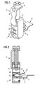
- Fig. 1 shows an inventive frame clamping element 1, which has a threaded fastener part 2 for receiving a screw 3 and a frame 4, in which a connector 5 is mounted.
- the fferan gleichteil 2 is preferably U-shaped with two legs 6, 7 and one, the two legs connecting transition areas 8.
- the frame 4 is preferably rectangular in shape with four side panels.
- the screw 3 is guided by the first leg 6 of the fferan gleichteils 2 and through the top 9 of the frame.
- the connecting piece 5 main connections can be introduced in the form of electrical lines.
- the connecting piece 5 is preferably formed as a U-shaped housing member having two legs 10, 11 and a connecting portion 12.
- the legs 10, 11 are preferably formed differently long, wherein the longer leg 11 has a preferably S-shaped extension 13.
- In the connection region 12 are a plurality, preferably two through openings 14 for small conductors or Off Power plug.
- a resilient element 15 is arranged, which preferably has two resilient clamping legs.
- Fig. 2 also the frame clamping element 1 according to the invention is shown.
- the second leg 7 of the SSan gleichteils 2 has a projection 16 on its underside.
- the connector 5 main terminals can be introduced in the form of electrical conductors.
- the resilient element 15 is arranged, which preferably has two resilient clamping legs 17, 18.
- the clamping leg 17 is preferably formed in its end region semi-concentric and rests on the longer leg 11 of the connecting piece 5.
- the second clamping leg 18 rests on the shorter leg 10 of the connecting piece 5 and has a tongue-like extension 19, which extends beyond the leg 10 of the connecting piece 5.
- Fig. 3 the connector 5 is shown, which is designed for receiving conductors and / or power supply connectors.
- the connecting piece 5 has a U-shaped main body with the two legs 10, 11 and a connecting portion 12. In this case, the longer leg 11 to the S-shaped extension 13.
- the connection region 12 are a plurality, preferably two through openings 14 for the connection of smaller conductors or power supply connector.
- the resilient element 15 is arranged, which preferably has two resilient clamping legs 17, 18.
- the clamping leg 17 of the resilient element 15 is preferably formed in its end region semi-concentric and rests on the longer leg 11 of the connecting piece 5.
- the second clamping leg 18 rests on the shorter leg 10 of the connecting piece 5 and has a tongue-like extension 19, which extends beyond the leg 10 of the connecting piece 5.
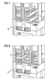
- Fig. 5 is an electromechanical switching device 20 with inventive frame clamping element 1 shows.
- the frame clamping element 1 has the front through the insertion openings 14 for small conductor and / or power supply connector.
- Fig. 6 shows a section Fig. 5 with the frame clamping element 1 according to the invention, wherein essentially the connection piece 5 is shown with its different slots.
- Fig. 7 shows the electromechanical switching device 20 with frame clamping element 1, in which electrical conductors 22 are clamped.
- Fig. 8 is an embodiment for an electromechanical switching device with frame clamping element 1 dardeterrorism, in which a power take-off connector 23 is inserted.
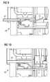
- Fig. 9 shows the connector 5 of the (2004)klemmelements 1 in its structural environment within an electromechanical switching device 20 with pre-positioned power supply connector 23.
- the power take-off connector 23 is guided through the insertion opening 14 of the connecting piece 5 in the interior of the connecting piece 5, where it meets the resilient element 15.
- connection piece 5 of the frame clamping element 5 is shown in its structural environment within an electromechanical switching device 20 with an attached power take-off connector 23.
- Out Fig. 10 shows that the power take-off connector 23 is mounted between the leg 10 of the connecting piece 5 and the clamping leg 18 of the resilient member 15.
- Fig. 11 shows the frame clamping element 1 in its structural environment within an electromechanical switching device 20 with clamped power take-off connector 23 during the release process by a screwdriver 24.
- the screwdriver 24 presses on the tongue-like projection 19 of the resilient element 15.
- the tongue-like projection 19 thereby dissolves from its anchoring, so that the power take-off plug 23 can be pulled out.
- the frame clamping element according to the invention is formed in one piece and allows the customer to connect at each port of an electromechanical switching device, a plurality of large conductors in screwing and a plurality of small conductors in spring technology.
Landscapes
- Connector Housings Or Holding Contact Members (AREA)
- Details Of Connecting Devices For Male And Female Coupling (AREA)
Priority Applications (1)
| Application Number | Priority Date | Filing Date | Title |
|---|---|---|---|
| EP10176568.3A EP2429037B1 (fr) | 2010-09-14 | 2010-09-14 | Elément de serrage de cadre pour commutateurs électromécaniques doté d'une pièce de raccordement intégrée |
Applications Claiming Priority (1)
| Application Number | Priority Date | Filing Date | Title |
|---|---|---|---|
| EP10176568.3A EP2429037B1 (fr) | 2010-09-14 | 2010-09-14 | Elément de serrage de cadre pour commutateurs électromécaniques doté d'une pièce de raccordement intégrée |
Publications (2)
| Publication Number | Publication Date |
|---|---|
| EP2429037A1 true EP2429037A1 (fr) | 2012-03-14 |
| EP2429037B1 EP2429037B1 (fr) | 2016-01-13 |
Family
ID=43502092
Family Applications (1)
| Application Number | Title | Priority Date | Filing Date |
|---|---|---|---|
| EP10176568.3A Not-in-force EP2429037B1 (fr) | 2010-09-14 | 2010-09-14 | Elément de serrage de cadre pour commutateurs électromécaniques doté d'une pièce de raccordement intégrée |
Country Status (1)
| Country | Link |
|---|---|
| EP (1) | EP2429037B1 (fr) |
Cited By (4)
| Publication number | Priority date | Publication date | Assignee | Title |
|---|---|---|---|---|
| EP2665129A1 (fr) * | 2012-05-14 | 2013-11-20 | Omron Corporation | Bloc de terminal |
| EP2849286A1 (fr) * | 2013-09-17 | 2015-03-18 | Schneider Electric Industries SAS | Borne à double système de raccordement électrique, en particulier pour un appareil de protection électrique basse tension, et appareil comportant une telle borne |
| CN105301298A (zh) * | 2015-11-30 | 2016-02-03 | 杭州西湖电子研究所 | 用于电力变压器自动化检测的分线夹具 |
| CN108493066A (zh) * | 2018-05-30 | 2018-09-04 | 乐清市高科环保电子有限公司 | 一种导电结构、连接单元及断路器 |
Citations (7)
| Publication number | Priority date | Publication date | Assignee | Title |
|---|---|---|---|---|
| DE1196742B (de) * | 1961-09-06 | 1965-07-15 | Siemens Ag | Klemme zum Verbinden elektrischer Leiterteile |
| DE3504317A1 (de) * | 1985-02-08 | 1986-08-14 | Licentia Patent-Verwaltungs-Gmbh, 6000 Frankfurt | Klemme fuer elektrische leiter |
| EP0893846A1 (fr) * | 1997-07-21 | 1999-01-27 | Abb Control | Appareil électrique portant un support de contact fixe et une borne de raccordement |
| EP1028489A1 (fr) * | 1999-02-10 | 2000-08-16 | ABBPATENT GmbH | Dispositif de bornes de connexion pour des conducteurs à fil et des conducteurs plats de barre omnibus pour un appareillage électrique |
| DE19934550A1 (de) * | 1999-07-20 | 2001-02-08 | Hager Electro Gmbh | Anschlußklemme für elektrische Leiter |
| EP1505692A1 (fr) * | 2003-07-22 | 2005-02-09 | Hager Electro | Dispositif de connexion double pour appareils èlectriques du type disjoncteur |
| EP1796214A1 (fr) * | 2005-12-09 | 2007-06-13 | Schneider Electric Industries Sas | Borne de connexion électrique et appareil électrique de coupure comportant une telle borne |
-
2010
- 2010-09-14 EP EP10176568.3A patent/EP2429037B1/fr not_active Not-in-force
Patent Citations (7)
| Publication number | Priority date | Publication date | Assignee | Title |
|---|---|---|---|---|
| DE1196742B (de) * | 1961-09-06 | 1965-07-15 | Siemens Ag | Klemme zum Verbinden elektrischer Leiterteile |
| DE3504317A1 (de) * | 1985-02-08 | 1986-08-14 | Licentia Patent-Verwaltungs-Gmbh, 6000 Frankfurt | Klemme fuer elektrische leiter |
| EP0893846A1 (fr) * | 1997-07-21 | 1999-01-27 | Abb Control | Appareil électrique portant un support de contact fixe et une borne de raccordement |
| EP1028489A1 (fr) * | 1999-02-10 | 2000-08-16 | ABBPATENT GmbH | Dispositif de bornes de connexion pour des conducteurs à fil et des conducteurs plats de barre omnibus pour un appareillage électrique |
| DE19934550A1 (de) * | 1999-07-20 | 2001-02-08 | Hager Electro Gmbh | Anschlußklemme für elektrische Leiter |
| EP1505692A1 (fr) * | 2003-07-22 | 2005-02-09 | Hager Electro | Dispositif de connexion double pour appareils èlectriques du type disjoncteur |
| EP1796214A1 (fr) * | 2005-12-09 | 2007-06-13 | Schneider Electric Industries Sas | Borne de connexion électrique et appareil électrique de coupure comportant une telle borne |
Cited By (9)
| Publication number | Priority date | Publication date | Assignee | Title |
|---|---|---|---|---|
| EP2665129A1 (fr) * | 2012-05-14 | 2013-11-20 | Omron Corporation | Bloc de terminal |
| CN103427171A (zh) * | 2012-05-14 | 2013-12-04 | 欧姆龙株式会社 | 端子平台块 |
| US9033727B2 (en) | 2012-05-14 | 2015-05-19 | Omron Corporation | Terminal platform block |
| CN103427171B (zh) * | 2012-05-14 | 2016-06-01 | 欧姆龙株式会社 | 端子平台块 |
| EP2849286A1 (fr) * | 2013-09-17 | 2015-03-18 | Schneider Electric Industries SAS | Borne à double système de raccordement électrique, en particulier pour un appareil de protection électrique basse tension, et appareil comportant une telle borne |
| FR3010838A1 (fr) * | 2013-09-17 | 2015-03-20 | Schneider Electric Ind Sas | Borne a double systeme de raccordement electrique, en particulier pour un appareil de protection electrique basse tension, et appareil comportant une telle borne |
| CN105301298A (zh) * | 2015-11-30 | 2016-02-03 | 杭州西湖电子研究所 | 用于电力变压器自动化检测的分线夹具 |
| CN105301298B (zh) * | 2015-11-30 | 2018-03-23 | 杭州西湖电子研究所 | 用于电力变压器自动化检测的分线夹具 |
| CN108493066A (zh) * | 2018-05-30 | 2018-09-04 | 乐清市高科环保电子有限公司 | 一种导电结构、连接单元及断路器 |
Also Published As
| Publication number | Publication date |
|---|---|
| EP2429037B1 (fr) | 2016-01-13 |
Similar Documents
| Publication | Publication Date | Title |
|---|---|---|
| EP1811604B1 (fr) | Barette à bornes électriques | |
| DE102013101830B4 (de) | Elektrische Anschlussklemme und Verfahren zu dessen Montage | |
| EP2255410B1 (fr) | Barrette a bornes ou bloc de barrettes a bornes | |
| EP3028345B1 (fr) | Élément de contact pour ensemble enfichable d'un système de bus guidé en particulier à l'extérieur | |
| DE102011113333B4 (de) | Elektrische Reihenklemme und Reihenklemmenblock | |
| EP2839544B1 (fr) | Bornier de test | |
| DE102012011676B4 (de) | Befestigungsklemme und Baueinheit mit zwei Befestigungsklemmen und mehreren nebeneinander angeordneten Reihenklemmen | |
| EP3342005B1 (fr) | Bloc de jonction électrique | |
| WO2012175205A1 (fr) | Borne de raccordement électrique | |
| EP2385540B1 (fr) | Dispositif de réception de sécurité, notamment pour boîtes de raccordement d'installations photovoltaïques | |
| EP3259807B1 (fr) | Bloc de jonction électrique | |
| EP2429037B1 (fr) | Elément de serrage de cadre pour commutateurs électromécaniques doté d'une pièce de raccordement intégrée | |
| DE102010040322A1 (de) | Schiebevorrichtung zur Befestigung eines Gehäuses | |
| DE102004040859B4 (de) | Elektrische Reihenklemme und Prüfstecker zur Verwendung bei einer elektrischen Klemme | |
| DE102008025433B4 (de) | Klemmenanschlußblock | |
| DE102008025432A1 (de) | KLemmenanschlußblock | |
| EP2936617A1 (fr) | Chambre de raccordement multiple à barre omnibus | |
| DE102010033112B4 (de) | Elektroinstallationsgerät | |
| DE202011000622U1 (de) | Sammelschienenabgreifklemme | |
| EP2489100B1 (fr) | Borne à vis avec couvercle et appareil de coupure d'installation | |
| DE102007058730A1 (de) | Adapter mit einem Kontaktteil, elektrische Verbindungsklemme oder elektrisches Gerät und Verwendung des Adapters | |
| WO2012013442A1 (fr) | Ensemble de bornes pour un sectionneur de puissance dans la technique des équilibreurs | |
| DE102011081037A1 (de) | Anschlussklemme und Schutzschaltgerät | |
| DE102008062852A1 (de) | Verbindungsanordnung mit einem elektrischen Gerät, insbesondere ein Schalt- oder Schutzgerät und einem weiteren Bauteil | |
| EP1983541A1 (fr) | Borne à vis et appareil d'installation |
Legal Events
| Date | Code | Title | Description |
|---|---|---|---|
| AK | Designated contracting states |
Kind code of ref document: A1 Designated state(s): AL AT BE BG CH CY CZ DE DK EE ES FI FR GB GR HR HU IE IS IT LI LT LU LV MC MK MT NL NO PL PT RO SE SI SK SM TR |
|
| AX | Request for extension of the european patent |
Extension state: BA ME RS |
|
| PUAI | Public reference made under article 153(3) epc to a published international application that has entered the european phase |
Free format text: ORIGINAL CODE: 0009012 |
|
| 17P | Request for examination filed |
Effective date: 20120606 |
|
| RAP1 | Party data changed (applicant data changed or rights of an application transferred) |
Owner name: SIEMENS AKTIENGESELLSCHAFT |
|
| GRAP | Despatch of communication of intention to grant a patent |
Free format text: ORIGINAL CODE: EPIDOSNIGR1 |
|
| RIC1 | Information provided on ipc code assigned before grant |
Ipc: H01R 4/38 20060101ALI20150629BHEP Ipc: H01R 4/48 20060101ALI20150629BHEP Ipc: H01R 4/36 20060101AFI20150629BHEP |
|
| INTG | Intention to grant announced |
Effective date: 20150803 |
|
| RIN1 | Information on inventor provided before grant (corrected) |
Inventor name: BODENMEIER, MARTIN Inventor name: SPERL, TOBIAS |
|
| GRAS | Grant fee paid |
Free format text: ORIGINAL CODE: EPIDOSNIGR3 |
|
| GRAA | (expected) grant |
Free format text: ORIGINAL CODE: 0009210 |
|
| AK | Designated contracting states |
Kind code of ref document: B1 Designated state(s): AL AT BE BG CH CY CZ DE DK EE ES FI FR GB GR HR HU IE IS IT LI LT LU LV MC MK MT NL NO PL PT RO SE SI SK SM TR |
|
| REG | Reference to a national code |
Ref country code: GB Ref legal event code: FG4D Free format text: NOT ENGLISH |
|
| REG | Reference to a national code |
Ref country code: CH Ref legal event code: EP |
|
| REG | Reference to a national code |
Ref country code: IE Ref legal event code: FG4D Free format text: LANGUAGE OF EP DOCUMENT: GERMAN |
|
| REG | Reference to a national code |
Ref country code: AT Ref legal event code: REF Ref document number: 771058 Country of ref document: AT Kind code of ref document: T Effective date: 20160215 |
|
| REG | Reference to a national code |
Ref country code: DE Ref legal event code: R096 Ref document number: 502010010928 Country of ref document: DE |
|
| REG | Reference to a national code |
Ref country code: LT Ref legal event code: MG4D |
|
| REG | Reference to a national code |
Ref country code: NL Ref legal event code: MP Effective date: 20160113 |
|
| PG25 | Lapsed in a contracting state [announced via postgrant information from national office to epo] |
Ref country code: NL Free format text: LAPSE BECAUSE OF FAILURE TO SUBMIT A TRANSLATION OF THE DESCRIPTION OR TO PAY THE FEE WITHIN THE PRESCRIBED TIME-LIMIT Effective date: 20160113 |
|
| PG25 | Lapsed in a contracting state [announced via postgrant information from national office to epo] |
Ref country code: FI Free format text: LAPSE BECAUSE OF FAILURE TO SUBMIT A TRANSLATION OF THE DESCRIPTION OR TO PAY THE FEE WITHIN THE PRESCRIBED TIME-LIMIT Effective date: 20160113 Ref country code: NO Free format text: LAPSE BECAUSE OF FAILURE TO SUBMIT A TRANSLATION OF THE DESCRIPTION OR TO PAY THE FEE WITHIN THE PRESCRIBED TIME-LIMIT Effective date: 20160413 Ref country code: ES Free format text: LAPSE BECAUSE OF FAILURE TO SUBMIT A TRANSLATION OF THE DESCRIPTION OR TO PAY THE FEE WITHIN THE PRESCRIBED TIME-LIMIT Effective date: 20160113 Ref country code: IT Free format text: LAPSE BECAUSE OF FAILURE TO SUBMIT A TRANSLATION OF THE DESCRIPTION OR TO PAY THE FEE WITHIN THE PRESCRIBED TIME-LIMIT Effective date: 20160113 Ref country code: GR Free format text: LAPSE BECAUSE OF FAILURE TO SUBMIT A TRANSLATION OF THE DESCRIPTION OR TO PAY THE FEE WITHIN THE PRESCRIBED TIME-LIMIT Effective date: 20160414 Ref country code: HR Free format text: LAPSE BECAUSE OF FAILURE TO SUBMIT A TRANSLATION OF THE DESCRIPTION OR TO PAY THE FEE WITHIN THE PRESCRIBED TIME-LIMIT Effective date: 20160113 |
|
| PG25 | Lapsed in a contracting state [announced via postgrant information from national office to epo] |
Ref country code: IS Free format text: LAPSE BECAUSE OF FAILURE TO SUBMIT A TRANSLATION OF THE DESCRIPTION OR TO PAY THE FEE WITHIN THE PRESCRIBED TIME-LIMIT Effective date: 20160513 Ref country code: PL Free format text: LAPSE BECAUSE OF FAILURE TO SUBMIT A TRANSLATION OF THE DESCRIPTION OR TO PAY THE FEE WITHIN THE PRESCRIBED TIME-LIMIT Effective date: 20160113 Ref country code: PT Free format text: LAPSE BECAUSE OF FAILURE TO SUBMIT A TRANSLATION OF THE DESCRIPTION OR TO PAY THE FEE WITHIN THE PRESCRIBED TIME-LIMIT Effective date: 20160513 Ref country code: LV Free format text: LAPSE BECAUSE OF FAILURE TO SUBMIT A TRANSLATION OF THE DESCRIPTION OR TO PAY THE FEE WITHIN THE PRESCRIBED TIME-LIMIT Effective date: 20160113 Ref country code: LT Free format text: LAPSE BECAUSE OF FAILURE TO SUBMIT A TRANSLATION OF THE DESCRIPTION OR TO PAY THE FEE WITHIN THE PRESCRIBED TIME-LIMIT Effective date: 20160113 Ref country code: SE Free format text: LAPSE BECAUSE OF FAILURE TO SUBMIT A TRANSLATION OF THE DESCRIPTION OR TO PAY THE FEE WITHIN THE PRESCRIBED TIME-LIMIT Effective date: 20160113 |
|
| REG | Reference to a national code |
Ref country code: FR Ref legal event code: PLFP Year of fee payment: 7 |
|
| REG | Reference to a national code |
Ref country code: DE Ref legal event code: R097 Ref document number: 502010010928 Country of ref document: DE |
|
| PG25 | Lapsed in a contracting state [announced via postgrant information from national office to epo] |
Ref country code: DK Free format text: LAPSE BECAUSE OF FAILURE TO SUBMIT A TRANSLATION OF THE DESCRIPTION OR TO PAY THE FEE WITHIN THE PRESCRIBED TIME-LIMIT Effective date: 20160113 Ref country code: EE Free format text: LAPSE BECAUSE OF FAILURE TO SUBMIT A TRANSLATION OF THE DESCRIPTION OR TO PAY THE FEE WITHIN THE PRESCRIBED TIME-LIMIT Effective date: 20160113 |
|
| PLBE | No opposition filed within time limit |
Free format text: ORIGINAL CODE: 0009261 |
|
| STAA | Information on the status of an ep patent application or granted ep patent |
Free format text: STATUS: NO OPPOSITION FILED WITHIN TIME LIMIT |
|
| PG25 | Lapsed in a contracting state [announced via postgrant information from national office to epo] |
Ref country code: CZ Free format text: LAPSE BECAUSE OF FAILURE TO SUBMIT A TRANSLATION OF THE DESCRIPTION OR TO PAY THE FEE WITHIN THE PRESCRIBED TIME-LIMIT Effective date: 20160113 Ref country code: SM Free format text: LAPSE BECAUSE OF FAILURE TO SUBMIT A TRANSLATION OF THE DESCRIPTION OR TO PAY THE FEE WITHIN THE PRESCRIBED TIME-LIMIT Effective date: 20160113 Ref country code: SK Free format text: LAPSE BECAUSE OF FAILURE TO SUBMIT A TRANSLATION OF THE DESCRIPTION OR TO PAY THE FEE WITHIN THE PRESCRIBED TIME-LIMIT Effective date: 20160113 Ref country code: RO Free format text: LAPSE BECAUSE OF FAILURE TO SUBMIT A TRANSLATION OF THE DESCRIPTION OR TO PAY THE FEE WITHIN THE PRESCRIBED TIME-LIMIT Effective date: 20160113 |
|
| 26N | No opposition filed |
Effective date: 20161014 |
|
| PG25 | Lapsed in a contracting state [announced via postgrant information from national office to epo] |
Ref country code: BE Free format text: LAPSE BECAUSE OF NON-PAYMENT OF DUE FEES Effective date: 20160930 Ref country code: BG Free format text: LAPSE BECAUSE OF FAILURE TO SUBMIT A TRANSLATION OF THE DESCRIPTION OR TO PAY THE FEE WITHIN THE PRESCRIBED TIME-LIMIT Effective date: 20160413 Ref country code: SI Free format text: LAPSE BECAUSE OF FAILURE TO SUBMIT A TRANSLATION OF THE DESCRIPTION OR TO PAY THE FEE WITHIN THE PRESCRIBED TIME-LIMIT Effective date: 20160113 |
|
| PG25 | Lapsed in a contracting state [announced via postgrant information from national office to epo] |
Ref country code: MC Free format text: LAPSE BECAUSE OF FAILURE TO SUBMIT A TRANSLATION OF THE DESCRIPTION OR TO PAY THE FEE WITHIN THE PRESCRIBED TIME-LIMIT Effective date: 20160113 |
|
| REG | Reference to a national code |
Ref country code: CH Ref legal event code: PL |
|
| GBPC | Gb: european patent ceased through non-payment of renewal fee |
Effective date: 20160914 |
|
| REG | Reference to a national code |
Ref country code: IE Ref legal event code: MM4A |
|
| PG25 | Lapsed in a contracting state [announced via postgrant information from national office to epo] |
Ref country code: IE Free format text: LAPSE BECAUSE OF NON-PAYMENT OF DUE FEES Effective date: 20160914 Ref country code: CH Free format text: LAPSE BECAUSE OF NON-PAYMENT OF DUE FEES Effective date: 20160930 Ref country code: LI Free format text: LAPSE BECAUSE OF NON-PAYMENT OF DUE FEES Effective date: 20160930 Ref country code: GB Free format text: LAPSE BECAUSE OF NON-PAYMENT OF DUE FEES Effective date: 20160914 |
|
| PG25 | Lapsed in a contracting state [announced via postgrant information from national office to epo] |
Ref country code: LU Free format text: LAPSE BECAUSE OF NON-PAYMENT OF DUE FEES Effective date: 20160914 |
|
| REG | Reference to a national code |
Ref country code: FR Ref legal event code: PLFP Year of fee payment: 8 |
|
| REG | Reference to a national code |
Ref country code: AT Ref legal event code: MM01 Ref document number: 771058 Country of ref document: AT Kind code of ref document: T Effective date: 20160914 |
|
| REG | Reference to a national code |
Ref country code: BE Ref legal event code: MM Effective date: 20160930 |
|
| PG25 | Lapsed in a contracting state [announced via postgrant information from national office to epo] |
Ref country code: AT Free format text: LAPSE BECAUSE OF NON-PAYMENT OF DUE FEES Effective date: 20160914 |
|
| PG25 | Lapsed in a contracting state [announced via postgrant information from national office to epo] |
Ref country code: CY Free format text: LAPSE BECAUSE OF FAILURE TO SUBMIT A TRANSLATION OF THE DESCRIPTION OR TO PAY THE FEE WITHIN THE PRESCRIBED TIME-LIMIT Effective date: 20160113 Ref country code: HU Free format text: LAPSE BECAUSE OF FAILURE TO SUBMIT A TRANSLATION OF THE DESCRIPTION OR TO PAY THE FEE WITHIN THE PRESCRIBED TIME-LIMIT; INVALID AB INITIO Effective date: 20100914 |
|
| PG25 | Lapsed in a contracting state [announced via postgrant information from national office to epo] |
Ref country code: MT Free format text: LAPSE BECAUSE OF FAILURE TO SUBMIT A TRANSLATION OF THE DESCRIPTION OR TO PAY THE FEE WITHIN THE PRESCRIBED TIME-LIMIT Effective date: 20160113 Ref country code: TR Free format text: LAPSE BECAUSE OF FAILURE TO SUBMIT A TRANSLATION OF THE DESCRIPTION OR TO PAY THE FEE WITHIN THE PRESCRIBED TIME-LIMIT Effective date: 20160113 Ref country code: MK Free format text: LAPSE BECAUSE OF FAILURE TO SUBMIT A TRANSLATION OF THE DESCRIPTION OR TO PAY THE FEE WITHIN THE PRESCRIBED TIME-LIMIT Effective date: 20160113 |
|
| REG | Reference to a national code |
Ref country code: FR Ref legal event code: PLFP Year of fee payment: 9 |
|
| PG25 | Lapsed in a contracting state [announced via postgrant information from national office to epo] |
Ref country code: AL Free format text: LAPSE BECAUSE OF FAILURE TO SUBMIT A TRANSLATION OF THE DESCRIPTION OR TO PAY THE FEE WITHIN THE PRESCRIBED TIME-LIMIT Effective date: 20160113 |
|
| PGFP | Annual fee paid to national office [announced via postgrant information from national office to epo] |
Ref country code: FR Payment date: 20190918 Year of fee payment: 10 |
|
| PGFP | Annual fee paid to national office [announced via postgrant information from national office to epo] |
Ref country code: DE Payment date: 20191119 Year of fee payment: 10 |
|
| REG | Reference to a national code |
Ref country code: DE Ref legal event code: R119 Ref document number: 502010010928 Country of ref document: DE |
|
| PG25 | Lapsed in a contracting state [announced via postgrant information from national office to epo] |
Ref country code: FR Free format text: LAPSE BECAUSE OF NON-PAYMENT OF DUE FEES Effective date: 20200930 Ref country code: DE Free format text: LAPSE BECAUSE OF NON-PAYMENT OF DUE FEES Effective date: 20210401 |