EP2425487B1 - Mechanismus zur wärmeableitung in einer antenne - Google Patents
Mechanismus zur wärmeableitung in einer antenne Download PDFInfo
- Publication number
- EP2425487B1 EP2425487B1 EP10719452.4A EP10719452A EP2425487B1 EP 2425487 B1 EP2425487 B1 EP 2425487B1 EP 10719452 A EP10719452 A EP 10719452A EP 2425487 B1 EP2425487 B1 EP 2425487B1
- Authority
- EP
- European Patent Office
- Prior art keywords
- absorbing member
- radar absorbing
- transmission system
- microwave
- hollow tubes
- Prior art date
- Legal status (The legal status is an assumption and is not a legal conclusion. Google has not performed a legal analysis and makes no representation as to the accuracy of the status listed.)
- Active
Links
Images

Classifications
-
- H—ELECTRICITY
- H01—ELECTRIC ELEMENTS
- H01Q—ANTENNAS, i.e. RADIO AERIALS
- H01Q1/00—Details of, or arrangements associated with, antennas
- H01Q1/42—Housings not intimately mechanically associated with radiating elements, e.g. radome
- H01Q1/421—Means for correcting aberrations introduced by a radome
-
- H—ELECTRICITY
- H01—ELECTRIC ELEMENTS
- H01Q—ANTENNAS, i.e. RADIO AERIALS
- H01Q1/00—Details of, or arrangements associated with, antennas
- H01Q1/02—Arrangements for de-icing; Arrangements for drying-out ; Arrangements for cooling; Arrangements for preventing corrosion
-
- H—ELECTRICITY
- H01—ELECTRIC ELEMENTS
- H01Q—ANTENNAS, i.e. RADIO AERIALS
- H01Q1/00—Details of, or arrangements associated with, antennas
- H01Q1/42—Housings not intimately mechanically associated with radiating elements, e.g. radome
- H01Q1/422—Housings not intimately mechanically associated with radiating elements, e.g. radome comprising two or more layers of dielectric material
-
- H—ELECTRICITY
- H01—ELECTRIC ELEMENTS
- H01Q—ANTENNAS, i.e. RADIO AERIALS
- H01Q17/00—Devices for absorbing waves radiated from an antenna; Combinations of such devices with active antenna elements or systems
- H01Q17/001—Devices for absorbing waves radiated from an antenna; Combinations of such devices with active antenna elements or systems for modifying the directional characteristic of an aerial
-
- H—ELECTRICITY
- H01—ELECTRIC ELEMENTS
- H01Q—ANTENNAS, i.e. RADIO AERIALS
- H01Q17/00—Devices for absorbing waves radiated from an antenna; Combinations of such devices with active antenna elements or systems
- H01Q17/002—Devices for absorbing waves radiated from an antenna; Combinations of such devices with active antenna elements or systems using short elongated elements as dissipative material, e.g. metallic threads or flake-like particles
Definitions
- This disclosure generally relates to antennas, and more particularly, to a thermal dissipation mechanism that may be used to absorb heat from a radar absorbing member of an antenna.
- Antennas operating in the microwave frequency range use various directing or reflecting elements with relatively precise physical characteristics.
- a protective covering commonly referred to as a radome may be placed over the antenna.
- the radome separates the elements of the antenna from various environmental aspects, such as precipitation, humidity, solar radiation, or other forms of debris that may compromise the performance of the antenna.
- An example of such a microwave antenna system can be found in EP 1635187 .
- a heat dissipation system includes an elongated radar absorbing member configured with a thermal dissipation mechanism.
- the radar absorbing member extends proximate a junction of a microwave antenna enclosure that houses an antenna and a radome that covers an opening in the microwave antenna enclosure.
- the radar absorbing member absorbs electro-magnetic energy incident upon the junction.
- the thermal dissipation mechanism absorbs heat generated by the absorbed electro-magnetic energy.
- one embodiment of the radar absorbing member configured with the thermal dissipation mechanism may allow increased output power density levels than may be provided by known radar absorbing member designs.
- Radar absorbing members are often used with radomes of microwave antennas to reduce its effective radar cross-section (RCS), reduce electro-magnetic interference, and/or improve the antenna's pattern. Because these radar absorbing members inherently absorb electro-magnetic radiation, they may limit the transmitted output power density generated by the microwave antenna.
- the thermal dissipation mechanism actively cools the radar absorbing member during operation; thus, the output power density level generated by the microwave antenna may be increased without causing excessive heating of the radar absorbing member and/or other components adjacent to the radar absorbing member, such as the radome configured on the microwave antenna.
- radomes may be positioned over an opening of the microwave antenna enclosure such that electro-magnetic radiation passes through freely while shielding its relatively delicate elements and associated electronics from the ambient environment.
- radomes may typically include low radio-frequency (RF) loss materials to not unduly affect the radiation pattern of the antenna.
- radomes may provide relatively good protection, their constituent materials may form an electrical discontinuity with adjacent antenna enclosures that house their respective antennas.
- the junction at the edge of the radome may be used to reduce the electro-magnetic interference (EMI) contribution to other co-located antennas by reducing the electro-magnetic energy trapped in the radome. It can also improve antenna pattern by reducing scattered contributions to sidelobe levels. It can also be used to reduce its radar cross-section (RCS).
- EMI electro-magnetic interference
- the junction may be covered by a radar absorbing material to absorb electro-magnetic radiation incident upon the junction. This radar absorbing material, however, may trap a significant amount of heat when used in conjunction with antennas that generate relatively high output power density signals.
- FIGURES 1A and 1B show one embodiment of a microwave antenna 10 that may benefit from the teachings of the present disclosure.
- Microwave antenna 10 includes one or more radiating elements 12 ( FIGURE 1B ) that are housed in an enclosure 14.
- Enclosure 14 has an opening 16 that is covered by a radome 18.
- the interface of enclosure 14 and radome 18 forms a junction 20 that is covered by a radar absorbing member 22.
- radar absorbing member 22 is configured with a thermal dissipation mechanism that removes heat from radar absorbing member 22 due to the transmission of electro-magnetic radiation by radiating elements 12.
- Radiating elements 12 may be any type of physical structure that transmits and/or receives electro-magnetic radiation. Radiating elements 12 transmit electro-magnetic radiation with an output power density that may cause heat build-up inside radar absorbing member 22. In some cases, radiating elements 12 generate electro-magnetic radiation having an output power density that is greater than 0.78 Watts per square cm (W/cm 2 ) or 5 Watts per square inch (W/in 2 ). Electro-magnetic radiation at these output power density levels may cause excessive heating within the radar absorbing member 22. In some cases, the radar absorbing member 22 may be helpful in improving the antenna performance or radar cross-section (RCS).
- RCS radar cross-section
- radar absorbing member 22 may be useful for enhancing the transparency of microwave antenna 10 from detection by radar, its electro-magnetic absorbing characteristic also absorbs electro-magnetic radiation generated by radiating elements 12. Because radar absorbing member 22 may be made of a generally thermally insulative material, it may experience excessive heat build-up when radiating elements 12 transmit electro-magnetic radiation. In some cases, this excessive heat build-up in radar absorbing member 22 may cause various types of damage to radome 18, such as delamination of the various layers of radome 18 from one another.
- FIGURE 2 is an enlarged, cross-sectional view of one embodiment of a thermal spreader 26 that may be configured in radar absorbing member 22.
- thermal spreader 26 is a type of thermal dissipation mechanism that may be disposed within radar absorbing member 22.
- Thermal spreader 26 is thermally coupled to radar absorbing member 22 and a support frame 28 configured on antenna enclosure 14 that may be used for attachment and support of radome 18 on enclosure 14.
- Thermal spreader 26 is formed of a thermally conductive material to conduct heat away from radar absorbing member 22.
- support frame 28 is made of a thermally conductive material, such as metal, that readily conducts heat away from radar absorbing member 22.
- Thermal spreader 26 may be thermally coupled to support frame 28 using any suitable approach.
- thermal spreader 26 is maintained in physical contact with radar absorbing member 22 and support frame 28 using fasteners, such as bolts, or a suitable adhesive.
- thermal coupling may be enhanced by a relatively thin layer of heat transfer compound, such as a ceramic-based thermal grease or a metal-based thermal grease that is sandwiched between thermal spreader 26 and support frame 28 and/or radar absorbing member 22.
- Thermal spreader 26 may be made of any suitable type of material.
- thermal spreader 26 is made of a metal, such as aluminum, that has a relatively high degree of thermal conductivity.
- thermal spreader 26 has a shape that does not unduly affect the propagation pattern of antenna elements 12 or adversely affect the transparency of microwave antenna 10 to radar detection.
- suitable materials for this purpose may include, aluminum, copper, chemical vapor deposition (CVD) diamond, pyrolytic graphite, K-1100 carbon fibers and copper infiltrated carbon fibers.
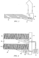
- FIGURE 3 is an enlarged, cross-sectional view of microwave antenna 10 incorporating an alternative embodiment of a thermal dissipation mechanism according to the teachings of the present disclosure.
- thermal dissipation mechanism includes one or more elongated hollow tubes 30a and 30b that convey a fluid coolant through corresponding radar absorbing members 32a and 32b.
- Hollow tubes 30a and 30b are fluidly coupled to an antenna cooling system 34 that cools the fluid coolant that has been heated by hollow tubes 30a and 30b.
- Hollow tubes 30a and 30b have an elongated extent that may extend through a portion or through the entire length of their associated elongated radar absorbing members 32a and 32b.
- Radome 34 as shown is a layered radome 34 having several core layers 36 alternatively disposed over a laminate layer 38 in which radar absorbing member 32b is disposed within the laminate layer 38.
- hollow tubes 30a and 30b may be configured in radar absorbing members 32a and 32b for use on any suitable type of radome having multiple layers as shown or on the radome 18 configuration as shown in FIGURE 2 .
- Hollow tubes 30a and 30b may have any suitable type of cross-sectional shape.
- hollow tubes 30a have a generally circular cross-sectional shape while the single hollow tube 30b has a cross-sectional shape that is generally similar to the shape of radar absorbing member 22, which in this particular case is triangular in shape.
- a fluid coolant flows through hollow tubes 30a and 30b to absorb heat generated inside radar absorbing member 22.
- This fluid coolant may operate as a two-phase fluid coolant in which the coolant enters hollow tubes 30a and 30b in liquid form and boils or vaporizes such that some or all of the fluid coolant leaves the hollow tubes 30a and 30b as a vapor.
- the fluid coolant may operate as a single-phase coolant in which the coolant enters hollow tubes 30a and 30b as a liquid, increases in temperature, and exits again in all or mostly liquid form.
- Heat absorbed by the fluid coolant may be removed in any suitable manner.
- movement of the fluid coolant through hollow tubes 30a and 30b may be provided by convection. That is, the heating of fluid coolant within radar absorbing member 22 causes its movement to another location where it may be cooled.
- hollow tubes 30a and 30b may be thermally coupled to radar enclosure 14 for cooling of the fluid coolant.
- hollow tubes 30a and 30b are coupled to antenna cooling system 34 that is also used to remove heat from other portions of microwave antenna 10.
- antenna cooling system 34 may be configured to receive heated fluid coolant from an electrical circuit that is used to generate electro-magnetic energy through antenna elements 12.
- the fluid coolant used in the embodiment of FIGURE 3 may include, but is not limited to, freon, polyalphaolefin, a mixture of ethylene glycol and water, a mixture of propylene glycol and water, a fluorinert and a range of isomers of an alkylated aromatic.
- the liquid may be a perfluorocarbon, such as octafluoropropane, perfluorohexane, or perfluorodecalin. These perfluorocarbons are relatively inert and generally electrically insulative making them well suited for use around microwave antenna 10.
- microwave antenna 10 without departing from the scope of the invention.
- the components used to make radar absorbing member 22 may be integrated or separated.
- hollow tubes 30a and/or 30b may be integrally formed with radar absorbing member 22 in which they are made of the same material from which radar absorbing material is made.
- the operations of the thermal dissipation mechanism may be performed by more, fewer, or other components.
- antenna cooling system may also include a thermometer that is coupled to radar absorbing member 22 for monitoring its operating temperature and thus, controlling its operating temperature within a specified range.
- each refers to each member of a set or each member of a subset of a set.
Landscapes
- Details Of Aerials (AREA)
- Aerials With Secondary Devices (AREA)
- Radar Systems Or Details Thereof (AREA)
Claims (12)
- Ein Mikrowellenübertragungssystem (10), umfassend:ein Mikrowellenantennengehäuse (14);ein Radom (18), das eine Öffnung (16) im Mikrowellenantennengehäuse (14) abdeckt, wobei das Mikrowellenantennengehäuse (14) und das Radom (18) aus unterschiedlichen Materialien hergestellt sind, sodass an der Verbindungsstelle (20) des Mikrowellenantennengehäuses (14) und des Radoms (18) eine elektrische Diskontinuität gebildet wird; undein längliches Radarabsorptionselement (22), das sich unmittelbar von der Verbindungsstelle (20) erstreckt, wobei das Radarabsorptionselement (22) funktioniert, um die elektromagnetische Energie, die auf die Verbindungsstelle (20) einfällt, zu absorbieren;gekennzeichnet durch einen Wärmeableitungsmechanismus (26), der in dem länglichen Radarabsorptionselement (22) ausgebildet ist und funktioniert, um Wärme von dem länglichen Radarabsorptionselement (22) zu entfernen.
- Das Mikrowellenübertragungssystem (10) von Anspruch 1, worin der Wärmeableitungsmechanismus (26) ein wärmeleitfähiges Material umfasst, welches das längliche Radarabsorptionselement (22) an das Mikrowellenantenenngehäuse (14) koppelt.
- Das Mikrowellenübertragungssystem (10) von Anspruch 2, worin das wärmeleitfähige Material ein metallisches Material umfasst.
- Das Mikrowellenübertragungssystem (10) von Anspruch 1, worin der Wärmeableitungsmechanismus (26) eine oder mehrere hohle Röhren (30) umfasst, die funktionsfähig sind, um ein Kühlmittel durch das längliche Radarabsorptionselement (22) zum Entfernen von Wärme aus dem länglichen Radarabsorptionselement (22) zu befördern.
- Das Mikrowellenübertragungssystem (10) von Anspruch 4, worin das Kühlmittel funktionsfähig ist, um mithilfe einer Konvektionswirkung des Kühlmittels durch die eine oder mehreren hohlen Röhren (30) befördert zu werden.
- Das Mikrowellenübertragungssystem (10) von Anspruch 4, worin das Kühlmittel funktionsfähig ist, um unter Verwendung einer Pumpe durch die eine oder mehreren hohlen Röhren (30) befördert zu werden.
- Das Mikrowellenübertragungssystem (10) von Anspruch 4, worin die eine oder mehreren hohlen Röhren (30) fluid an ein Kühlsystem (34) einer Mikrowellenantenne gekoppelt sind, die im Mikrowellenantennengehäuse (14) ausgebildet ist, welches ein oder mehrere Strahlungselemente (12) aufweist, wobei das Kühlsystem (34) funktionsfähig ist, um Wärme von den Strahlungselementen (12) und dem Radarabsorptionselement (22) zu entfernen.
- Das Mikrowellenübertragungssystem (10) von Anspruch 4, worin die eine oder mehreren hohlen Röhren (30) thermisch an einen Stützrahmen (28) des Mikrowellenantennengehäuses (14) gekoppelt sind, sodass der Stützrahmen (28) Wärme von der einen oder mehreren hohlen Röhren empfängt.
- Das Mikrowellenübertragungssystem (10) von Anspruch 4, worin die eine oder mehreren hohlen Röhren (30) eine kreisförmige Querschnittsform aufweist.
- Das Mikrowellenübertragungssystem (10) von Anspruch 4, worin die eine oder mehreren hohlen Röhren (30) eine einzelne Röhre (30b) umfassen, die eine Querschnittsform aufweist, welche im Allgemeinen ähnlich wie eine Querschnittsform des Radarabsorptionselements (22) ist.
- Das Mikrowellenübertragungssystem (10) von Anspruch 10, worin das Radarabsorptionselement (22) einen keilförmigen Querschnitt aufweist.
- Das Mikrowellenübertragungssystem (10) von Anspruch 1, worin das Mikrowellenantennengehäuse (14) ein Antennenelement (12) beinhaltet, das funktionsfähig ist, um die elektromagnetische Energie mit einer Leistungsdichte von mehr als 0,78 Watt pro cm2 (5 Watt pro Quadratzoll) zu erzeugen.
Applications Claiming Priority (2)
| Application Number | Priority Date | Filing Date | Title |
|---|---|---|---|
| US12/432,496 US8045329B2 (en) | 2009-04-29 | 2009-04-29 | Thermal dissipation mechanism for an antenna |
| PCT/US2010/031539 WO2010126728A1 (en) | 2009-04-29 | 2010-04-19 | Thermal dissipation mechanism for an antenna |
Publications (2)
| Publication Number | Publication Date |
|---|---|
| EP2425487A1 EP2425487A1 (de) | 2012-03-07 |
| EP2425487B1 true EP2425487B1 (de) | 2013-12-18 |
Family
ID=42313001
Family Applications (1)
| Application Number | Title | Priority Date | Filing Date |
|---|---|---|---|
| EP10719452.4A Active EP2425487B1 (de) | 2009-04-29 | 2010-04-19 | Mechanismus zur wärmeableitung in einer antenne |
Country Status (4)
| Country | Link |
|---|---|
| US (1) | US8045329B2 (de) |
| EP (1) | EP2425487B1 (de) |
| ES (1) | ES2446351T3 (de) |
| WO (1) | WO2010126728A1 (de) |
Families Citing this family (15)
| Publication number | Priority date | Publication date | Assignee | Title |
|---|---|---|---|---|
| US8933860B2 (en) * | 2012-06-12 | 2015-01-13 | Integral Laser Solutions, Inc. | Active cooling of high speed seeker missile domes and radomes |
| CN102769185A (zh) * | 2012-06-29 | 2012-11-07 | 常州亚邦天线有限公司 | 天线防护罩 |
| US20140354064A1 (en) * | 2013-05-29 | 2014-12-04 | Escape Dynamics, Inc. | System and method for safe, wireless energy transmission |
| US20170347490A1 (en) * | 2016-05-24 | 2017-11-30 | Texas Instruments Incorporated | High-frequency antenna structure with high thermal conductivity and high surface area |
| CN107942292A (zh) * | 2017-10-27 | 2018-04-20 | 四川嘉义雷科电子技术有限公司 | 设置有气体冷却装置的测距设备 |
| US10910706B2 (en) * | 2018-01-19 | 2021-02-02 | Mediatek Inc. | Radar sensor housing design |
| EP3780260B1 (de) * | 2018-04-11 | 2024-10-23 | KMW Inc. | Antennenvorrichtung mit mehreren eingängen und mehreren ausgängen |
| CN110048229B (zh) * | 2019-04-01 | 2023-11-21 | 贵州航天电子科技有限公司 | 一种高效防泄漏的保护罩 |
| US12244052B2 (en) * | 2020-06-26 | 2025-03-04 | Motorola Mobility Llc | Communication device having a heat sink antenna |
| CN111902019B (zh) * | 2020-07-16 | 2022-10-18 | 上海无线电设备研究所 | 一种星载相控阵雷达的热控装置 |
| US11382205B2 (en) * | 2020-09-16 | 2022-07-05 | Aptiv Technologies Limited | Heatsink shield with thermal-contact dimples for thermal-energy distribution in a radar assembly |
| CN213989165U (zh) * | 2020-10-13 | 2021-08-17 | 深圳市大疆创新科技有限公司 | 雷达装置、雷达安装装置及可移动设备 |
| DE102021124090A1 (de) | 2021-09-17 | 2023-03-23 | 4A Manufacturing Gmbh | Integrierte Rahmenstruktur |
| CN114051359B (zh) * | 2021-10-26 | 2022-10-21 | 华睿交通科技股份有限公司 | 温度场仿真方法 |
| CN116454584B (zh) * | 2023-04-23 | 2023-10-27 | 安徽耀峰雷达科技有限公司 | 一种精确散热的雷达天线结构 |
Family Cites Families (39)
| Publication number | Priority date | Publication date | Assignee | Title |
|---|---|---|---|---|
| GB870917A (en) | 1957-10-11 | 1961-06-21 | Microcell Ltd | Improvements in or relating to cooling aircraft or component parts thereof |
| US3818983A (en) * | 1972-09-18 | 1974-06-25 | Borg Warner | Cooled enclosure |
| US4044396A (en) * | 1975-08-14 | 1977-08-23 | The United States Of America As Represented By The Secretary Of The Air Force | Heat pipe cooling of airborne phased array radar |
| US4057104A (en) * | 1976-08-26 | 1977-11-08 | Westinghouse Electric Corporation | Temperature controlled airborne electronic assembly |
| US4493010A (en) * | 1982-11-05 | 1985-01-08 | Lockheed Corporation | Electronic packaging module utilizing phase-change conductive cooling |
| US4998181A (en) * | 1987-12-15 | 1991-03-05 | Texas Instruments Incorporated | Coldplate for cooling electronic equipment |
| US5276455A (en) * | 1991-05-24 | 1994-01-04 | The Boeing Company | Packaging architecture for phased arrays |
| US5488380A (en) * | 1991-05-24 | 1996-01-30 | The Boeing Company | Packaging architecture for phased arrays |
| US5423498A (en) * | 1993-04-27 | 1995-06-13 | E-Systems, Inc. | Modular liquid skin heat exchanger |
| US5570092A (en) * | 1994-04-11 | 1996-10-29 | Hughes Danbury Optical Systems, Inc. | Reduction of scatter from material discontinuities |
| US5960861A (en) * | 1995-04-05 | 1999-10-05 | Raytheon Company | Cold plate design for thermal management of phase array-radar systems |
| JP2957463B2 (ja) * | 1996-03-11 | 1999-10-04 | 日本電気株式会社 | パッチアンテナおよびその製造方法 |
| US5930117A (en) * | 1996-05-07 | 1999-07-27 | Sheldahl, Inc. | Heat sink structure comprising a microarray of thermal metal heat channels or vias in a polymeric or film layer |
| JPH1051213A (ja) * | 1996-08-05 | 1998-02-20 | Toshiba Corp | 空中線装置 |
| US6059017A (en) * | 1998-04-20 | 2000-05-09 | The United States Of America As Represented By The Secretary Of The Navy | Directional heat exchanger |
| US6084772A (en) * | 1998-09-03 | 2000-07-04 | Nortel Networks Corporation | Electronics enclosure for power electronics with passive thermal management |
| US7069975B1 (en) * | 1999-09-16 | 2006-07-04 | Raytheon Company | Method and apparatus for cooling with a phase change material and heat pipes |
| US6377219B2 (en) * | 2000-01-11 | 2002-04-23 | Cool Options, Inc. | Composite molded antenna assembly |
| CA2405143A1 (en) * | 2000-04-07 | 2001-10-18 | The Chief Controller, Research And Development | Transmit/receiver module for active phased array antenna |
| US7017651B1 (en) * | 2000-09-13 | 2006-03-28 | Raytheon Company | Method and apparatus for temperature gradient control in an electronic system |
| US6388317B1 (en) * | 2000-09-25 | 2002-05-14 | Lockheed Martin Corporation | Solid-state chip cooling by use of microchannel coolant flow |
| US6456224B1 (en) * | 2001-07-05 | 2002-09-24 | Northrop Grummancorporation | Edge concealment system for abating radar detectability of aircraft |
| US7178586B2 (en) * | 2001-07-13 | 2007-02-20 | Lytron, Inc. | Flattened tube cold plate for liquid cooling electrical components |
| JP2003298270A (ja) * | 2002-03-29 | 2003-10-17 | Mitsubishi Electric Corp | アンテナ装置 |
| US6937471B1 (en) * | 2002-07-11 | 2005-08-30 | Raytheon Company | Method and apparatus for removing heat from a circuit |
| US6836131B2 (en) * | 2002-08-16 | 2004-12-28 | Credence Systems Corp. | Spray cooling and transparent cooling plate thermal management system |
| JP2004077399A (ja) | 2002-08-22 | 2004-03-11 | Hitachi Ltd | ミリ波レーダ |
| EP1404024B1 (de) * | 2002-09-27 | 2008-07-30 | Fujitsu Limited | Funkgerät für Freilufteinsatz |
| US7061446B1 (en) * | 2002-10-24 | 2006-06-13 | Raytheon Company | Method and apparatus for controlling temperature gradients within a structure being cooled |
| US6952345B2 (en) * | 2003-10-31 | 2005-10-04 | Raytheon Company | Method and apparatus for cooling heat-generating structure |
| US7138958B2 (en) * | 2004-02-27 | 2006-11-21 | Andrew Corporation | Reflector antenna radome with backlobe suppressor ring and method of manufacturing |
| US7292439B2 (en) * | 2005-01-19 | 2007-11-06 | Raytheon Company | Thermal management system and method for electronic assemblies |
| US7443354B2 (en) * | 2005-08-09 | 2008-10-28 | The Boeing Company | Compliant, internally cooled antenna apparatus and method |
| US7545323B2 (en) * | 2005-10-31 | 2009-06-09 | The Boeing Company | Phased array antenna systems and methods |
| US20080106482A1 (en) * | 2006-11-08 | 2008-05-08 | Alan Cherrette | Electronically scanned hemispheric antenna |
| US7548424B2 (en) * | 2007-03-12 | 2009-06-16 | Raytheon Company | Distributed transmit/receive integrated microwave module chip level cooling system |
| US7940524B2 (en) * | 2007-10-01 | 2011-05-10 | Raytheon Company | Remote cooling of a phased array antenna |
| US8698691B2 (en) * | 2008-07-30 | 2014-04-15 | Ratheon Company | Internal cooling system for a radome |
| US8497812B2 (en) * | 2009-01-30 | 2013-07-30 | Raytheon Company | Composite radome and radiator structure |
-
2009
- 2009-04-29 US US12/432,496 patent/US8045329B2/en active Active
-
2010
- 2010-04-19 WO PCT/US2010/031539 patent/WO2010126728A1/en not_active Ceased
- 2010-04-19 ES ES10719452.4T patent/ES2446351T3/es active Active
- 2010-04-19 EP EP10719452.4A patent/EP2425487B1/de active Active
Also Published As
| Publication number | Publication date |
|---|---|
| EP2425487A1 (de) | 2012-03-07 |
| ES2446351T3 (es) | 2014-03-07 |
| US8045329B2 (en) | 2011-10-25 |
| WO2010126728A1 (en) | 2010-11-04 |
| US20100277867A1 (en) | 2010-11-04 |
Similar Documents
| Publication | Publication Date | Title |
|---|---|---|
| EP2425487B1 (de) | Mechanismus zur wärmeableitung in einer antenne | |
| KR100995082B1 (ko) | 안테나 모듈의 온도 제어 시스템 | |
| JP5469745B2 (ja) | アビオニクスシャーシ | |
| JP5624381B2 (ja) | アビオニクス用シャーシ | |
| US8222541B2 (en) | Avionics chassis | |
| JP2012531039A (ja) | アビオニクスシャーシ | |
| EP2313946B3 (de) | Radom mit einem internen kühlsystem | |
| CN101032053B (zh) | 用于贴片天线的引脚形鳍片接地面 | |
| WO1992003034A1 (en) | Heat-conductive metal ceramic composite material panel system for improved heat dissipation | |
| KR20040089097A (ko) | 로시 매체를 포함하는 emi실딩 | |
| US9674984B2 (en) | Plastic chassis for liquid cooled electronic components | |
| JP2009099753A (ja) | ヒートシンク | |
| WO2019221054A1 (ja) | アンテナ、アレイアンテナ及び無線通信装置 | |
| EP2494649B1 (de) | Wärmeeffizienter dielektrischer resonatorträger | |
| KR20180047977A (ko) | 레이더 장치 및 그의 케이스 구조 | |
| JPWO2008035540A1 (ja) | 電子装置搭載機器とその共振抑制方法 | |
| CN117013881A (zh) | 一种电磁波到直流电的能量转换装置 | |
| Zhou et al. | Substrate integrated waveguides slot antenna array with heatsink enclosed | |
| CN120728206B (zh) | 一种微波合路器 | |
| Marwaha | Surekha Rani, Anupma Marwaha & | |
| CN119450982A (zh) | 一种无线访问接入点设备 | |
| CN121507386A (zh) | 辐射振子结构以及天线单元 | |
| JP2009253253A (ja) | 冷却フィン | |
| HUP0700251A2 (hu) | Elektromos fûtõrendszer radommal ellátott mikrohullámú parabolaantennához |
Legal Events
| Date | Code | Title | Description |
|---|---|---|---|
| PUAI | Public reference made under article 153(3) epc to a published international application that has entered the european phase |
Free format text: ORIGINAL CODE: 0009012 |
|
| 17P | Request for examination filed |
Effective date: 20111117 |
|
| AK | Designated contracting states |
Kind code of ref document: A1 Designated state(s): AT BE BG CH CY CZ DE DK EE ES FI FR GB GR HR HU IE IS IT LI LT LU LV MC MK MT NL NO PL PT RO SE SI SK SM TR |
|
| DAX | Request for extension of the european patent (deleted) | ||
| GRAP | Despatch of communication of intention to grant a patent |
Free format text: ORIGINAL CODE: EPIDOSNIGR1 |
|
| INTG | Intention to grant announced |
Effective date: 20130715 |
|
| GRAS | Grant fee paid |
Free format text: ORIGINAL CODE: EPIDOSNIGR3 |
|
| GRAA | (expected) grant |
Free format text: ORIGINAL CODE: 0009210 |
|
| AK | Designated contracting states |
Kind code of ref document: B1 Designated state(s): AT BE BG CH CY CZ DE DK EE ES FI FR GB GR HR HU IE IS IT LI LT LU LV MC MK MT NL NO PL PT RO SE SI SK SM TR |
|
| REG | Reference to a national code |
Ref country code: GB Ref legal event code: FG4D |
|
| REG | Reference to a national code |
Ref country code: CH Ref legal event code: EP |
|
| REG | Reference to a national code |
Ref country code: AT Ref legal event code: REF Ref document number: 645955 Country of ref document: AT Kind code of ref document: T Effective date: 20140115 |
|
| REG | Reference to a national code |
Ref country code: IE Ref legal event code: FG4D |
|
| REG | Reference to a national code |
Ref country code: DE Ref legal event code: R096 Ref document number: 602010012514 Country of ref document: DE Effective date: 20140213 |
|
| REG | Reference to a national code |
Ref country code: ES Ref legal event code: FG2A Ref document number: 2446351 Country of ref document: ES Kind code of ref document: T3 Effective date: 20140307 |
|
| REG | Reference to a national code |
Ref country code: NL Ref legal event code: VDEP Effective date: 20131218 |
|
| PG25 | Lapsed in a contracting state [announced via postgrant information from national office to epo] |
Ref country code: HR Free format text: LAPSE BECAUSE OF FAILURE TO SUBMIT A TRANSLATION OF THE DESCRIPTION OR TO PAY THE FEE WITHIN THE PRESCRIBED TIME-LIMIT Effective date: 20131218 Ref country code: FI Free format text: LAPSE BECAUSE OF FAILURE TO SUBMIT A TRANSLATION OF THE DESCRIPTION OR TO PAY THE FEE WITHIN THE PRESCRIBED TIME-LIMIT Effective date: 20131218 Ref country code: LT Free format text: LAPSE BECAUSE OF FAILURE TO SUBMIT A TRANSLATION OF THE DESCRIPTION OR TO PAY THE FEE WITHIN THE PRESCRIBED TIME-LIMIT Effective date: 20131218 Ref country code: NO Free format text: LAPSE BECAUSE OF FAILURE TO SUBMIT A TRANSLATION OF THE DESCRIPTION OR TO PAY THE FEE WITHIN THE PRESCRIBED TIME-LIMIT Effective date: 20140318 Ref country code: SE Free format text: LAPSE BECAUSE OF FAILURE TO SUBMIT A TRANSLATION OF THE DESCRIPTION OR TO PAY THE FEE WITHIN THE PRESCRIBED TIME-LIMIT Effective date: 20131218 |
|
| REG | Reference to a national code |
Ref country code: AT Ref legal event code: MK05 Ref document number: 645955 Country of ref document: AT Kind code of ref document: T Effective date: 20131218 |
|
| REG | Reference to a national code |
Ref country code: LT Ref legal event code: MG4D |
|
| PG25 | Lapsed in a contracting state [announced via postgrant information from national office to epo] |
Ref country code: LV Free format text: LAPSE BECAUSE OF FAILURE TO SUBMIT A TRANSLATION OF THE DESCRIPTION OR TO PAY THE FEE WITHIN THE PRESCRIBED TIME-LIMIT Effective date: 20131218 |
|
| PG25 | Lapsed in a contracting state [announced via postgrant information from national office to epo] |
Ref country code: IS Free format text: LAPSE BECAUSE OF FAILURE TO SUBMIT A TRANSLATION OF THE DESCRIPTION OR TO PAY THE FEE WITHIN THE PRESCRIBED TIME-LIMIT Effective date: 20140418 Ref country code: EE Free format text: LAPSE BECAUSE OF FAILURE TO SUBMIT A TRANSLATION OF THE DESCRIPTION OR TO PAY THE FEE WITHIN THE PRESCRIBED TIME-LIMIT Effective date: 20131218 Ref country code: BE Free format text: LAPSE BECAUSE OF FAILURE TO SUBMIT A TRANSLATION OF THE DESCRIPTION OR TO PAY THE FEE WITHIN THE PRESCRIBED TIME-LIMIT Effective date: 20131218 |
|
| PG25 | Lapsed in a contracting state [announced via postgrant information from national office to epo] |
Ref country code: AT Free format text: LAPSE BECAUSE OF FAILURE TO SUBMIT A TRANSLATION OF THE DESCRIPTION OR TO PAY THE FEE WITHIN THE PRESCRIBED TIME-LIMIT Effective date: 20131218 Ref country code: PL Free format text: LAPSE BECAUSE OF FAILURE TO SUBMIT A TRANSLATION OF THE DESCRIPTION OR TO PAY THE FEE WITHIN THE PRESCRIBED TIME-LIMIT Effective date: 20131218 Ref country code: PT Free format text: LAPSE BECAUSE OF FAILURE TO SUBMIT A TRANSLATION OF THE DESCRIPTION OR TO PAY THE FEE WITHIN THE PRESCRIBED TIME-LIMIT Effective date: 20140418 Ref country code: SK Free format text: LAPSE BECAUSE OF FAILURE TO SUBMIT A TRANSLATION OF THE DESCRIPTION OR TO PAY THE FEE WITHIN THE PRESCRIBED TIME-LIMIT Effective date: 20131218 Ref country code: RO Free format text: LAPSE BECAUSE OF FAILURE TO SUBMIT A TRANSLATION OF THE DESCRIPTION OR TO PAY THE FEE WITHIN THE PRESCRIBED TIME-LIMIT Effective date: 20131218 Ref country code: NL Free format text: LAPSE BECAUSE OF FAILURE TO SUBMIT A TRANSLATION OF THE DESCRIPTION OR TO PAY THE FEE WITHIN THE PRESCRIBED TIME-LIMIT Effective date: 20131218 Ref country code: CY Free format text: LAPSE BECAUSE OF FAILURE TO SUBMIT A TRANSLATION OF THE DESCRIPTION OR TO PAY THE FEE WITHIN THE PRESCRIBED TIME-LIMIT Effective date: 20131218 Ref country code: CZ Free format text: LAPSE BECAUSE OF FAILURE TO SUBMIT A TRANSLATION OF THE DESCRIPTION OR TO PAY THE FEE WITHIN THE PRESCRIBED TIME-LIMIT Effective date: 20131218 |
|
| REG | Reference to a national code |
Ref country code: DE Ref legal event code: R097 Ref document number: 602010012514 Country of ref document: DE |
|
| PLBE | No opposition filed within time limit |
Free format text: ORIGINAL CODE: 0009261 |
|
| STAA | Information on the status of an ep patent application or granted ep patent |
Free format text: STATUS: NO OPPOSITION FILED WITHIN TIME LIMIT |
|
| PG25 | Lapsed in a contracting state [announced via postgrant information from national office to epo] |
Ref country code: DK Free format text: LAPSE BECAUSE OF FAILURE TO SUBMIT A TRANSLATION OF THE DESCRIPTION OR TO PAY THE FEE WITHIN THE PRESCRIBED TIME-LIMIT Effective date: 20131218 |
|
| 26N | No opposition filed |
Effective date: 20140919 |
|
| PG25 | Lapsed in a contracting state [announced via postgrant information from national office to epo] |
Ref country code: MC Free format text: LAPSE BECAUSE OF FAILURE TO SUBMIT A TRANSLATION OF THE DESCRIPTION OR TO PAY THE FEE WITHIN THE PRESCRIBED TIME-LIMIT Effective date: 20131218 Ref country code: LU Free format text: LAPSE BECAUSE OF FAILURE TO SUBMIT A TRANSLATION OF THE DESCRIPTION OR TO PAY THE FEE WITHIN THE PRESCRIBED TIME-LIMIT Effective date: 20140419 |
|
| REG | Reference to a national code |
Ref country code: CH Ref legal event code: PL |
|
| REG | Reference to a national code |
Ref country code: DE Ref legal event code: R097 Ref document number: 602010012514 Country of ref document: DE Effective date: 20140919 |
|
| REG | Reference to a national code |
Ref country code: IE Ref legal event code: MM4A |
|
| PG25 | Lapsed in a contracting state [announced via postgrant information from national office to epo] |
Ref country code: LI Free format text: LAPSE BECAUSE OF NON-PAYMENT OF DUE FEES Effective date: 20140430 Ref country code: CH Free format text: LAPSE BECAUSE OF NON-PAYMENT OF DUE FEES Effective date: 20140430 |
|
| PG25 | Lapsed in a contracting state [announced via postgrant information from national office to epo] |
Ref country code: IE Free format text: LAPSE BECAUSE OF NON-PAYMENT OF DUE FEES Effective date: 20140419 |
|
| PG25 | Lapsed in a contracting state [announced via postgrant information from national office to epo] |
Ref country code: SI Free format text: LAPSE BECAUSE OF FAILURE TO SUBMIT A TRANSLATION OF THE DESCRIPTION OR TO PAY THE FEE WITHIN THE PRESCRIBED TIME-LIMIT Effective date: 20131218 |
|
| REG | Reference to a national code |
Ref country code: FR Ref legal event code: PLFP Year of fee payment: 7 |
|
| PG25 | Lapsed in a contracting state [announced via postgrant information from national office to epo] |
Ref country code: MT Free format text: LAPSE BECAUSE OF FAILURE TO SUBMIT A TRANSLATION OF THE DESCRIPTION OR TO PAY THE FEE WITHIN THE PRESCRIBED TIME-LIMIT Effective date: 20131218 |
|
| PG25 | Lapsed in a contracting state [announced via postgrant information from national office to epo] |
Ref country code: SM Free format text: LAPSE BECAUSE OF FAILURE TO SUBMIT A TRANSLATION OF THE DESCRIPTION OR TO PAY THE FEE WITHIN THE PRESCRIBED TIME-LIMIT Effective date: 20131218 |
|
| PG25 | Lapsed in a contracting state [announced via postgrant information from national office to epo] |
Ref country code: GR Free format text: LAPSE BECAUSE OF FAILURE TO SUBMIT A TRANSLATION OF THE DESCRIPTION OR TO PAY THE FEE WITHIN THE PRESCRIBED TIME-LIMIT Effective date: 20140319 Ref country code: BG Free format text: LAPSE BECAUSE OF FAILURE TO SUBMIT A TRANSLATION OF THE DESCRIPTION OR TO PAY THE FEE WITHIN THE PRESCRIBED TIME-LIMIT Effective date: 20131218 |
|
| PG25 | Lapsed in a contracting state [announced via postgrant information from national office to epo] |
Ref country code: TR Free format text: LAPSE BECAUSE OF FAILURE TO SUBMIT A TRANSLATION OF THE DESCRIPTION OR TO PAY THE FEE WITHIN THE PRESCRIBED TIME-LIMIT Effective date: 20131218 Ref country code: HU Free format text: LAPSE BECAUSE OF FAILURE TO SUBMIT A TRANSLATION OF THE DESCRIPTION OR TO PAY THE FEE WITHIN THE PRESCRIBED TIME-LIMIT; INVALID AB INITIO Effective date: 20100419 |
|
| REG | Reference to a national code |
Ref country code: FR Ref legal event code: PLFP Year of fee payment: 8 |
|
| REG | Reference to a national code |
Ref country code: FR Ref legal event code: PLFP Year of fee payment: 9 |
|
| PG25 | Lapsed in a contracting state [announced via postgrant information from national office to epo] |
Ref country code: MK Free format text: LAPSE BECAUSE OF FAILURE TO SUBMIT A TRANSLATION OF THE DESCRIPTION OR TO PAY THE FEE WITHIN THE PRESCRIBED TIME-LIMIT Effective date: 20131218 |
|
| P01 | Opt-out of the competence of the unified patent court (upc) registered |
Effective date: 20230530 |
|
| PGFP | Annual fee paid to national office [announced via postgrant information from national office to epo] |
Ref country code: FR Payment date: 20250319 Year of fee payment: 16 |
|
| PGFP | Annual fee paid to national office [announced via postgrant information from national office to epo] |
Ref country code: IT Payment date: 20250319 Year of fee payment: 16 Ref country code: GB Payment date: 20250319 Year of fee payment: 16 |
|
| PGFP | Annual fee paid to national office [announced via postgrant information from national office to epo] |
Ref country code: DE Payment date: 20250319 Year of fee payment: 16 |
|
| PGFP | Annual fee paid to national office [announced via postgrant information from national office to epo] |
Ref country code: ES Payment date: 20250502 Year of fee payment: 16 |