EP2425229B1 - Ansteuer- und auswerteschaltung, messgerät sowie verfahren zum messen der konzentration eines gases - Google Patents
Ansteuer- und auswerteschaltung, messgerät sowie verfahren zum messen der konzentration eines gases Download PDFInfo
- Publication number
- EP2425229B1 EP2425229B1 EP10722567.4A EP10722567A EP2425229B1 EP 2425229 B1 EP2425229 B1 EP 2425229B1 EP 10722567 A EP10722567 A EP 10722567A EP 2425229 B1 EP2425229 B1 EP 2425229B1
- Authority
- EP
- European Patent Office
- Prior art keywords
- digital
- signal
- gas
- analog converter
- analog
- Prior art date
- Legal status (The legal status is an assumption and is not a legal conclusion. Google has not performed a legal analysis and makes no representation as to the accuracy of the status listed.)
- Not-in-force
Links
Images
Classifications
-
- G—PHYSICS
- G01—MEASURING; TESTING
- G01N—INVESTIGATING OR ANALYSING MATERIALS BY DETERMINING THEIR CHEMICAL OR PHYSICAL PROPERTIES
- G01N21/00—Investigating or analysing materials by the use of optical means, i.e. using sub-millimetre waves, infrared, visible or ultraviolet light
- G01N21/17—Systems in which incident light is modified in accordance with the properties of the material investigated
- G01N21/25—Colour; Spectral properties, i.e. comparison of effect of material on the light at two or more different wavelengths or wavelength bands
- G01N21/31—Investigating relative effect of material at wavelengths characteristic of specific elements or molecules, e.g. atomic absorption spectrometry
- G01N21/39—Investigating relative effect of material at wavelengths characteristic of specific elements or molecules, e.g. atomic absorption spectrometry using tunable lasers
-
- G—PHYSICS
- G01—MEASURING; TESTING
- G01J—MEASUREMENT OF INTENSITY, VELOCITY, SPECTRAL CONTENT, POLARISATION, PHASE OR PULSE CHARACTERISTICS OF INFRARED, VISIBLE OR ULTRAVIOLET LIGHT; COLORIMETRY; RADIATION PYROMETRY
- G01J1/00—Photometry, e.g. photographic exposure meter
- G01J1/42—Photometry, e.g. photographic exposure meter using electric radiation detectors
- G01J1/4257—Photometry, e.g. photographic exposure meter using electric radiation detectors applied to monitoring the characteristics of a beam, e.g. laser beam, headlamp beam
-
- G—PHYSICS
- G01—MEASURING; TESTING
- G01N—INVESTIGATING OR ANALYSING MATERIALS BY DETERMINING THEIR CHEMICAL OR PHYSICAL PROPERTIES
- G01N21/00—Investigating or analysing materials by the use of optical means, i.e. using sub-millimetre waves, infrared, visible or ultraviolet light
- G01N21/17—Systems in which incident light is modified in accordance with the properties of the material investigated
- G01N21/25—Colour; Spectral properties, i.e. comparison of effect of material on the light at two or more different wavelengths or wavelength bands
- G01N21/27—Colour; Spectral properties, i.e. comparison of effect of material on the light at two or more different wavelengths or wavelength bands using photo-electric detection ; circuits for computing concentration
- G01N21/274—Calibration, base line adjustment, drift correction
-
- G—PHYSICS
- G01—MEASURING; TESTING
- G01N—INVESTIGATING OR ANALYSING MATERIALS BY DETERMINING THEIR CHEMICAL OR PHYSICAL PROPERTIES
- G01N21/00—Investigating or analysing materials by the use of optical means, i.e. using sub-millimetre waves, infrared, visible or ultraviolet light
- G01N21/17—Systems in which incident light is modified in accordance with the properties of the material investigated
- G01N21/25—Colour; Spectral properties, i.e. comparison of effect of material on the light at two or more different wavelengths or wavelength bands
- G01N21/31—Investigating relative effect of material at wavelengths characteristic of specific elements or molecules, e.g. atomic absorption spectrometry
- G01N21/35—Investigating relative effect of material at wavelengths characteristic of specific elements or molecules, e.g. atomic absorption spectrometry using infrared light
- G01N21/3504—Investigating relative effect of material at wavelengths characteristic of specific elements or molecules, e.g. atomic absorption spectrometry using infrared light for analysing gases, e.g. multi-gas analysis
-
- G—PHYSICS
- G01—MEASURING; TESTING
- G01N—INVESTIGATING OR ANALYSING MATERIALS BY DETERMINING THEIR CHEMICAL OR PHYSICAL PROPERTIES
- G01N21/00—Investigating or analysing materials by the use of optical means, i.e. using sub-millimetre waves, infrared, visible or ultraviolet light
- G01N21/17—Systems in which incident light is modified in accordance with the properties of the material investigated
- G01N21/59—Transmissivity
- G01N21/61—Non-dispersive gas analysers
-
- G—PHYSICS
- G01—MEASURING; TESTING
- G01N—INVESTIGATING OR ANALYSING MATERIALS BY DETERMINING THEIR CHEMICAL OR PHYSICAL PROPERTIES
- G01N21/00—Investigating or analysing materials by the use of optical means, i.e. using sub-millimetre waves, infrared, visible or ultraviolet light
- G01N21/84—Systems specially adapted for particular applications
- G01N21/85—Investigating moving fluids or granular solids
- G01N21/8507—Probe photometers, i.e. with optical measuring part dipped into fluid sample
-
- G—PHYSICS
- G01—MEASURING; TESTING
- G01N—INVESTIGATING OR ANALYSING MATERIALS BY DETERMINING THEIR CHEMICAL OR PHYSICAL PROPERTIES
- G01N21/00—Investigating or analysing materials by the use of optical means, i.e. using sub-millimetre waves, infrared, visible or ultraviolet light
- G01N21/17—Systems in which incident light is modified in accordance with the properties of the material investigated
- G01N21/25—Colour; Spectral properties, i.e. comparison of effect of material on the light at two or more different wavelengths or wavelength bands
- G01N21/31—Investigating relative effect of material at wavelengths characteristic of specific elements or molecules, e.g. atomic absorption spectrometry
- G01N21/39—Investigating relative effect of material at wavelengths characteristic of specific elements or molecules, e.g. atomic absorption spectrometry using tunable lasers
- G01N2021/396—Type of laser source
- G01N2021/399—Diode laser
-
- G—PHYSICS
- G01—MEASURING; TESTING
- G01N—INVESTIGATING OR ANALYSING MATERIALS BY DETERMINING THEIR CHEMICAL OR PHYSICAL PROPERTIES
- G01N2201/00—Features of devices classified in G01N21/00
- G01N2201/06—Illumination; Optics
- G01N2201/061—Sources
- G01N2201/06113—Coherent sources; lasers
- G01N2201/0612—Laser diodes
-
- G—PHYSICS
- G01—MEASURING; TESTING
- G01N—INVESTIGATING OR ANALYSING MATERIALS BY DETERMINING THEIR CHEMICAL OR PHYSICAL PROPERTIES
- G01N2201/00—Features of devices classified in G01N21/00
- G01N2201/06—Illumination; Optics
- G01N2201/069—Supply of sources
- G01N2201/0691—Modulated (not pulsed supply)
-
- G—PHYSICS
- G01—MEASURING; TESTING
- G01N—INVESTIGATING OR ANALYSING MATERIALS BY DETERMINING THEIR CHEMICAL OR PHYSICAL PROPERTIES
- G01N2201/00—Features of devices classified in G01N21/00
- G01N2201/12—Circuits of general importance; Signal processing
- G01N2201/121—Correction signals
-
- G—PHYSICS
- G01—MEASURING; TESTING
- G01N—INVESTIGATING OR ANALYSING MATERIALS BY DETERMINING THEIR CHEMICAL OR PHYSICAL PROPERTIES
- G01N2201/00—Features of devices classified in G01N21/00
- G01N2201/12—Circuits of general importance; Signal processing
- G01N2201/124—Sensitivity
- G01N2201/1245—Averaging several measurements
-
- G—PHYSICS
- G01—MEASURING; TESTING
- G01N—INVESTIGATING OR ANALYSING MATERIALS BY DETERMINING THEIR CHEMICAL OR PHYSICAL PROPERTIES
- G01N2201/00—Features of devices classified in G01N21/00
- G01N2201/12—Circuits of general importance; Signal processing
- G01N2201/127—Calibration; base line adjustment; drift compensation
- G01N2201/12746—Calibration values determination
- G01N2201/12753—Calibration values determination and storage
Definitions
- the invention relates to the field of control and evaluation circuits referred to in the preamble of claim 1. Art, measuring devices with such a circuit and method referred to in the preamble of claim 7 Art.
- the invention relates to the determination of the concentration of one or more gases by transmission measurement.
- the transmission measurement determines the absorption of an absorption line of the or each gas and deduces from this the concentration of or each of the gases.
- tunable semiconductor lasers have come on the market whose line width is significantly narrower than the typical absorption line of a gas of interest here of about 1 nm, and whose laser line can be changed by more than 1 nm by the strength of the current flowing through the semiconductor laser current.
- the change of the laser line is in particular due to a change in the refractive index to a higher temperature of the semiconductor crystal.
- the refractive index change has about a 20-fold greater influence on the wavelength than the change in the spatial Expansion of the semiconductor crystal with the same temperature change.
- Such semiconductor lasers are used for space analysis, in particular for expedition to other planets.
- the strongly nonlinear characteristic of the semiconductor laser must be calculated by a fit of the measuring points. Such a method is from the US 2006/0044562 A1 known, wherein the characteristic of the semiconductor laser is approximated by a straight line.
- a similar procedure is from the US 6,091,504 known. However, this method works with two detectors. A beam splitter directs a portion of the laser light onto a first detector. The other part of the laser light is directed through a gas sample line to a second detector. Both detector signals are supplied to a compensation circuit which removes the carrier waveform (sawtooth) with which the semiconductor laser which generates the laser light is driven. A similar procedure with 2 detectors is from the US 6,150,661 known. Another, similar gas detector is from the WO 2008/079032 A2 known. In this case, the signal for driving the laser is generated by an addition of three signals by means of an operational amplifier. The first two signals, namely a sine and a triangle signal, are generated by direct digital synthesis. The third signal is a calibration voltage offset generated by a digital-to-analog converter or pulse width modulator under the control of a microprocessor.
- the EP 1 475 618 A1 discloses a wavelength modulation spectroscopy system.
- the frequency of a laser is modulated with a sinusoidal fundamental.
- the frequency modulation is partially converted into amplitude modulation.
- One measures at a harmonic of the fundamental because the laser is less noisy there.
- the sinusoidal fundamental wave is pre-distorted by adding a harmonic.
- the object is achieved in that a reference signal is subtracted from the received from a photodiode transmission signal.
- a reference signal is subtracted from the received from a photodiode transmission signal.
- a digital memory is used to store a characteristic curve.
- An analog addition of an offset to the signal supplied by a second digital-to-analog converter to generate an analog signal to drive the semiconductor laser keeps the dynamic range and thus the cost of the second digital-to-analog converter low.
- the address lines of the digital memory for storing a characteristic curve can be advantageously connected to the digital inputs of the second digital-to-analog converter. This reduces the complexity of the required control signals.
- a symmetrical sawtooth signal at the digital inputs of the second digital-to-analog converter ensures uniform heating and cooling of the semiconductor crystal of the laser and thus for a uniform passage through the absorption line of the gas to be measured.
- the area under the absorption line of the gas to be measured is easily obtained and thus a measure of the concentration of the gas to be measured.
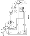
- FIG. 1 a schematic diagram of the control and evaluation circuit according to the invention.
- FIG. 1 shows a schematic diagram of the control and evaluation circuit according to the invention.
- the gas to be measured may be co-located with other gases in a cuvette 2. Pneumatic connections on the cuvette allow gas exchange in the cuvette 2.
- Light in the region of an absorption line of the gas to be measured is transmitted through a distributed feedback (DFB) semiconductor laser 1 ) generated. Transmitted light is converted by a photodiode 3 into an electric current.
- a current-to-voltage converter 4 converts the current supplied by the photodiode 3 into a voltage. It is known to those skilled in the art that a current-to-voltage converter 4 may include an operational amplifier fed back through a resistor and, if necessary, an inverter. The output signal of the current-voltage converter 4 is referred to as the transmission signal 21.
- a subtracter 5 subtracts the transmission signal 21 from a reference signal 20.
- the subtractor supplies a difference signal which is fed to an analog-to-digital converter 6.
- the analog-to-digital converter 6 samples at a frequency of 5 to 10 kHz.
- the subtracter 5 may have an offset adjustment 19 in order to optimally use the dynamic range of the analog-to-digital converter 6 and to keep the required resolution and thus the costs of the analog-to-digital converter 6 low.
- the digital output signal of the analog-to-digital converter 6 can be supplied to a computer 7 or a microprocessor.
- the computer 7 or a microprocessor generates a digital control signal, which is supplied to both the address inputs of the memory 8, as well as the digital-to-analog converter 10.
- the control signal has, for example, a periodic, in particular symmetrical, sawtooth time course and a frequency of 5 Hz.
- the digital-to-analog converter 10 generates from the digital control signal an analog control signal to which the differential amplifier 11 in cooperation with the resistors 12 and 13 a first offset added.
- This first offset roughly matches the semiconductor laser 1 to the absorption line to be measured, so that the semiconductor laser 1 at the minimum output voltage of the digital-to-analog converter 10 light with a frequency above the absorption line and at maximum output voltage of the digital-to-analog converter 10 generates light at a frequency below the absorption line. It is also possible to set the first offset so that, in the case of a control signal equal to the arithmetic mean of minimum and maximum control signal, laser light is generated whose frequency corresponds to the maximum of the absorption line. In this way, the dynamics of the digital-to-analog converter 10 is used optimally. Moreover, the differential amplifier 11 also assumes the function of a power amplifier, so that, in particular, sufficient current is made available for the semiconductor laser 1. The current through the semiconductor laser is also referred to as a drive signal 17.
- this compensation is effected by the memory 8.
- suitable values are stored which correspond to the transmission signal 21 at a zero concentration of the gas to be measured, so that the difference signal at the output of the subtractor 5 is as zero as possible.
- Zero concentration can be understood as the concentration that the gas to be measured has in the ambient air. This concentration is not zero, in particular for the gases N 2 and O 2 . Even with CO 2 , it may be necessary to consider the approximately 0.04% share in the air. This definition of zero concentration allows easy calibration of the device in the ambient air. Alternatively, a gas cylinder with a gas mixture of known composition or a calibration cuvette with an enclosed test gas can also be used for the calibration.
- the semiconductor laser 1 (manufacturer: Nanoplus GmbH, serial number 350 / 10-23) is mounted in a TO5 housing by means of a mounts.
- the mount includes a Peltier element 14 and a thermistor 15. Therefore, the Peltier element 14 and the housing of the semiconductor laser 1 are in thermal contact 24, which in the FIG. 1 is shown by a dashed line.
- the Peltier element is driven by a driver 16.
- In the in FIG. 1 illustrated embodiment includes the Computer 7 a feedback loop from the thermistor 15 via the driver 16 to the Peltier element 14, so that the temperature of the mounts is kept largely constant and thus in particular unaffected by ambient temperature fluctuations.
- the temperature of the semiconductor laser 1 itself deviates more or less from the temperature of the mounts depending on the height of the control signal.
- any conventional memory module can be used as the memory 8.
- pure ROM Read Only Memory
- Writable, non-volatile memories such as EEPROMs (Electrically Erasable Programmable ROM) are well suited.
- EEPROMs Electrical Erasable Programmable ROM
- FIG. 1 In the embodiment shown, even a RAM (random access memory) is used, into which the memory cells are rewritten each time the device is switched on (booting) via the data line 22.
- a computer 7 has a nonvolatile memory such as a hard disk.
- the data line 22 allows recalibration.
- the evaluation of the difference signal is performed by integration over the n-times passing through an absorption line, where n is a natural number (1, 2, 3, ...) and you get an integral signal.
- n is a natural number (1, 2, 3, ...)
- Each falling and each rising edge of the symmetrical, sawtooth-shaped control signal corresponds to passing through the absorption line. It is thus integrated over a time that takes one or more rising and / or falling edges of the control signal.
- This can be done analogously by an integrator or digitally by summing the samples supplied by the analog-to-digital converter 6.
- the latter is in the in FIG. 1 realized embodiment illustrated.
- the integration or summation of the noise is pressed to an acceptable level.
- the integral signal has a good proportionality to the gas concentration, more precisely to the deviation of the gas concentration from the zero concentration.
- the difference signal will fluctuate at least between two values corresponding to ⁇ 1/2 bit of the resolution of the digital-to-analog converters 9 and 10.
- the two values may depend on the level of the digital control signal due to the non-linear characteristic of the semiconductor laser 1.
- the accuracy can be improved by otherwise the same parameters stored in the memory 8 values be calculated so that the integral signal as possible only varies by a value corresponding to ⁇ 1/2-bit resolution of the digital-to-analog converter 9 and 10.
- FIG. 1 shown embodiment used only for measuring the O 2 concentration at a wavelength of 760.26 nm. It is envisaged to determine concentrations of the following gases: CO, O 2 , CO 2 , C 2 H 2 , CH 4 , He, SF 6 and NO.
Landscapes
- Physics & Mathematics (AREA)
- Spectroscopy & Molecular Physics (AREA)
- General Physics & Mathematics (AREA)
- General Health & Medical Sciences (AREA)
- Life Sciences & Earth Sciences (AREA)
- Chemical & Material Sciences (AREA)
- Analytical Chemistry (AREA)
- Biochemistry (AREA)
- Health & Medical Sciences (AREA)
- Immunology (AREA)
- Pathology (AREA)
- Optics & Photonics (AREA)
- Engineering & Computer Science (AREA)
- Mathematical Physics (AREA)
- Theoretical Computer Science (AREA)
- Investigating Or Analysing Materials By Optical Means (AREA)
Description
- Die Erfindung bezieht sich auf das Gebiet von Ansteuer- und Auswerteschaltungen der im Oberbegriff des Patentanspruchs 1 genannten Art, Messgeräte mit einer solchen Schaltung sowie Verfahren der im Oberbegriff des Patentanspruchs 7 genannten Art.
- Die Erfindung bezieht sich auf die Bestimmung der Konzentration eines oder mehrerer Gase durch Transmissionsmessung. Insbesondere wird durch die Transmissionsmessung die Absorption einer Absorptionslinie des bzw. jedes Gases bestimmt und hieraus auf die Konzentration des beziehungsweise jedes der Gase geschlossen.
- Im Stand der Technik sind verschiedene Messanordnungen und -verfahren bekannt, bei denen aufgrund der Absorption einer Absorptionslinie eines Gases auf die Konzentration des Gases in einem Messvolumen geschlossen wird. Im Prinzip können diese Verfahren auch zur Analyse von Gasgemischen verwendet werden, wobei für jedes Gas mindestens eine Messung in einer Absorptionslinie erfolgen muss und idealerweise jede Absorptionslinie in einem anderen Bereich des Lichtspektrums liegen sollte. Im folgenden werden wir uns auf die Bestimmung der Konzentration eines einzigen Gases, beispielsweise O2, CO2, He oder N2 in Luft beschränken. Bei Gasen, die natürlicherweise in nennenswerten Umfang in natürlicher Luft vorkommen, also O2 und N2, eventuell auch CO2, wird unter Konzentration die absolut vorhandene Gasmenge verstanden. Medizintechnische Messverfahren, bei denen die Konzentration der oben genannten Gase gemessen wird, sind u. a. in der
EP 1772098 A1 (VI11P) beschrieben. - Kürzlich sind durchstimmbare Halbleiterlaser auf den Markt gekommen, deren Linienbreite deutlich schmaler als die typische Absorptionslinie eines hier interessierenden Gases von ca 1 nm ist, und deren Laserlinie um mehr als 1 nm durch die Stärke des durch den Halbleiterlaser fließenden Stromes verändert werden kann. Die Veränderung der Laserlinie ist insbesondere über eine Änderung des Brechungsindex auf eine höhere Temperatur des Halbleiterkristallszurückzuführen. Die Brechungsindexänderung hat einen ca 20-fach stärkeren Einfluss auf die Wellenlänge als die Änderung der räumlichen Ausdehnung des Halbleiterkristalls bei gleicher Temperaturänderung. Solche Halbleiterlaser werden für Analysen in der Raumfahrt, insbesondere bei Expedition im zu anderen Planeten, eingesetzt. Um die Absorption des zu messenden Gases zu bestimmen, muss die stark nichtlineare Kennlinie des Halbleiterlasers durch einen Fit aus den Messpunkten herausgerechnet werden. Ein solches Verfahren ist aus der
US 2006/0044562 A1 bekannt, wobei die Kennlinie des Halbleiterlasers durch eine Gerade angenähert wird. - Ein ähnliches Verfahren ist aus der
US 6,091,504 bekannt. Allerdings arbeitet dieses Verfahren mit zwei Detektoren. Ein Strahlteiler lenkt einen Teil des Laserlichts auf einen ersten Detektor. Der andere Teil des Laserlichts wird durch eine Gasprobenzeile auf einen zweiten Detektor gelenkt. Beide Detektorsignale werden einer Kompensationsschaltung zugeführt, die die Trägerwellenform (Sägezahn) entfernt, mit der der Halbleiterlaser angesteuert wird, der das Laserlicht erzeugt. Ein ähnliches Verfahren mit 2 Detektoren ist aus derUS 6,150,661 bekannt. Ein weiterer, ähnlicher Gasdetektor ist aus derWO 2008/079032 A2 bekannt. Dabei wird das Signal zur Ansteuerung der Laser durch eine Addition von drei Signalen mittels eines Operationsverstärkers erzeugt. Die ersten beiden Signale, nämlich ein Sinus- und Dreieckssignal werden mittels direkter digitaler Synthese erzeugt. Das dritte Signal ist ein Geichspannungsoffset, der von einem Digital-Analog-Wandler oder Pulsweitenmodulator unter Steuerung eines Mikroprozessors erzeugt wird. - Die
EP 1 475 618 A1 offenbart ein Wellenlängen-Modulations-Spektroskopie-System. Die Frequenz eines Lasers wird mit einer sinusförmigen Grundwelle moduliert.
Durch Wechselwirkung mit einer Gasprobe wird die Frequenzmodulation teilweise in Amplitudenmodulation umgewandelt. Man misst bei einer Oberwelle der Grundwelle, weil dort der Laser weniger rauscht. Um kostengünstige, weniger lineare Laser einsetzen zu können, wird die sinusförmige Grundwelle durch Addition einer Oberwelle vorverzerrt. - Es ist Aufgabe der Erfindung eine Ansteuer- und Auswerteschaltung sowie ein entsprechendes Verfahren anzugeben, das auf irdische Verhältnisse abgestimmt ist.
- Diese Aufgabe wird durch den Gegenstand der unabhängigen Ansprüche gelöst.
- Insbesondere wird die Aufgabe dadurch gelöst, dass ein Referenzsignal von dem von einer Fotodiode aufgenommenen Transmissionssignal abgezogen wird. Hierdurch wird die nichtlineare Kennlinie des Halbleiterlasers auf überraschend einfache Weise kompensiert. Das möglicherweise geringfügig höhere Gewicht spielt 5 auf der Erde keine Rolle.
- Bevorzugte Ausführungsformen der Erfindung sind Gegenstand der Unteransprüche.
- Erfindungsgemäß wird zur Speicherung einer Kennlinie ein digitaler Speicher eingesetzt.
- Aufgrund der guten Dynamik und einfachen Bauweise von analogen Subtrahierern wird die Subtraktion des Transmissionssignals vom Referenzsignal analog durchgeführt. Der hierfür erforderliche Digital-Analog-Wandler ist billiger als ein entsprechender Analog-Digital-Wandler und stellt somit kein gewichtiges Argument gegen eine analoge Subtraktion dar.
- Eine analoge Addition eines Offsets zu dem von einem zweiten Digital-Analog-Wandler gelieferten Signals zur Erzeugung eines analogen Signals zur Ansteuerung des Halbleiterlasers hält den Dynamikbereich und damit die Kosten des zweiten Digital-Analog-Wandlers gering.
- Die Adressleitungen des digitalen Speichers zur Speicherung einer Kennlinie können in vorteilhafter Weise mit den digitalen Eingängen des zweiten Digital-Analog-Wandlers verbunden sein. Dies reduziert die Komplexität der erforderlichen Steuersignale.
- Ein symmetrisches Sägezahnsignal an den digitalen Eingängen des zweiten Digital-Analog-Wandlers sorgt für eine gleichmäßige Erwärmung und Abkühlung des Halbleiterkristalls des Lasers und damit für ein gleichmäßiges Durchfahren der Absorptionslinie des zu messenden Gases.
- Durch Integration des Ausgangssignal des Subtrahierers entweder über eine Periode des Treibersignals oder die Zeitdauer von einem Minimum bis zu einem Maximum des Treibersignals oder die Zeitdauer von einem Maximum bis zu einem Minimum des Treibersignals erhält man auf einfache Weise die Fläche unter der Absorptionslinie des zu messenden Gases und damit ein Maß für die Konzentration des zu messenden Gases.
- Im Folgenden wird eine bevorzugte Ausführungsform der Erfindung unter Bezugnahme auf die beiliegenden Zeichnungen näher erläutert. Dabei zeigt
Fig. 1 einen Prinzipschaltplan der erfindungsgemäßen Ansteuer- und Auswerteschaltung. -
Figur 1 zeigt einen Prinzipschaltplan der erfindungsgemäßen Ansteuer- und Auswerteschaltung. Das zu messende Gas befindet sich möglicherweise zusammen mit anderen Gasen in einer Küvette 2. Pneumatische Anschlüsse an der Küvette ermöglichen einen Gasaustausch in der Küvette 2. Licht im Bereich einer Absorptionslinie des zu messenden Gases wird durch einen DFB-Halbleiterlaser 1 (DFB: distributed feedback) erzeugt. Transmittiertes Licht wird durch eine Fotodiode 3 in einen elektrischen Strom gewandelt. Ein Strom-Spannungs-Wandler 4 wandelt den von der Fotodiode 3 gelieferten Strom in eine Spannung. Fachleuten ist bekannt, dass ein Strom-Spannung-Wandler 4 einen durch einen Widerstand rückgekoppelten Operationsverstärker und, falls erforderlich, einen Inverter enthalten kann. Das Ausgangssignal des Strom-Spannung-Wandlers 4 wird als Transmissionssignal 21 bezeichnet. - Ein Subtrahierer 5 subtrahiert das Transmissionssignal 21 von einem Referenzsignal 20. Der Subtrahierer liefert ein Differenzsignal, das einem Analog-Digital-Wandler 6 zugeführt wird. Der Analog-Digital-Wandler 6 tastet mit einer Frequenz von 5 bis 10 kHz ab. Der Subtrahierer 5 kann einen Offset-Abgleich 19 aufweisen, um den Dynamikbereich des Analog-Digital-Wandlers 6 optimal zu nutzen und die erforderliche Auflösung und damit die Kosten des Analog-Digital-Wandlers 6 gering zu halten. Das digitale Ausgangssignal des Analog-Digital-Wandlers 6 kann einem Computer 7 oder einem Mikroprozessor zugeführt werden.
- Der Computer 7 oder ein Mikroprozessor erzeugt ein digitales Steuersignal, das sowohl den Adresseingängen des Speichers 8, als auch dem Digital-Analog-Wandler 10 zugeführt wird. Das Steuersignal hat beispielsweise einen periodischen, insbesondere symmetrischen, sägezahnförmigen zeitlichen Verlauf und eine Frequenz von 5 Hz. Der Digital-Analog-Wandler 10 erzeugt aus dem digitalen Steuersignal ein analoges Steuersignal, zu dem der Differenzverstärker 11 im Zusammenwirken mit den Widerständen 12 und 13 einen ersten Offset addiert. Dieser erste Offset stimmt den Halbleiterlaser 1 grob auf die zu messende Absorptionslinie ab, so dass der Halbleiterlaser 1 bei der minimalen Ausgangspannung des Digital-Analog-Wandlers 10 Licht mit einer Frequenz oberhalb der Absorptionslinie und bei maximaler Ausgangspannung des Digital-Analog-Wandlers 10 Licht mit einer Frequenz unterhalb der Absorptionslinie erzeugt. Man kann den ersten Offset auch so einstellen, dass bei einem Steuersignal gleich dem arithmetische Mittel aus minimalem und maximalem Steuersignal Laserlicht erzeugt wird, dessen Frequenz dem Maximum der Absorptionslinie entspricht. Auf diese Art und Weise wird die Dynamik des Digital-Analog-Wandlers 10 optimal genutzt. Im übrigen übernimmt der Differenzverstärker 11 auch die Funktion eines Leistungsverstärkers, so dass insbesondere genügend Strom für den Halbleiterlaser 1 zur Verfügung gestellt wird. Der Strom durch den Halbleiterlaser wird auch als Treibersignal 17 bezeichnet.
- Bei einer Änderung des Stroms durch den Halbleiterlaser 1 ändert sich nicht nur die Frequenz des emittierten Lichts, was bei dieser Anwendung erwünscht ist, sondern es ändert sich auch die Intensität des emittierten Lichts, was irgendwie kompensiert werden muss. Erfindungsgemäß erfolgt diese Kompensation durch den Speicher 8. In den Speicherzellen des Speichers 8 sind geeignete Werte abgelegt, die dem Transmissionssignal 21 bei einer Nullkonzentration des zu messenden Gases entsprechen, so dass das Differenzsignal am Ausgang des Subtrahierers 5 möglichst null ist.
- Unter Nullkonzentration kann die Konzentration verstanden werden, die das zu messende Gas in der Umgebungsluft hat. Diese Konzentration ist insbesondere für die Gase N2 und O2 ungleich null. Auch bei CO2 kann es erforderlich sein, die etwa 0,04% Anteil in der Luft zu berücksichtigen. Diese Definition der Nullkonzentration ermöglicht eine einfache Kalibrierung des Geräts in der Umgebungsluft. Alternativ kann auch eine Gasflasche mit einem Gasgemisch bekannter Zusammensetzung oder eine Kalibrierküvette mit einem eingeschlossenen Testgas zur Kalibrierung verwendet werden.
- Der Halbleiterlaser 1 (Hersteller: Nanoplus GmbH, Seriennummer 350/10-23) ist in einem TO5-Gehäuse mittels eines Mounts befestigt. Der Mount enthält ein Peltierelement 14 und einen Thermistor 15. Deshalb stehen das Peltierelement 14 und das Gehäuse des Halbleiterlasers 1 in thermischen Kontakt 24, der in der
Figur 1 durch eine gestrichelte Linie dargestellt ist. Das Peltierelement wird von einem Treiber 16 angesteuert. In der inFigur 1 dargestellten Ausführungsform schließt der Computer 7 eine Rückkoppelschleife vom Thermistor 15 über den Treiber 16 zum Peltierelement 14, so dass die Temperatur des Mounts weit gehend konstant gehalten wird und damit insbesondere von Umgebungstemperaturschwankungen unbeeinflusst bleibt. Die Temperatur des Halbleiterlasers 1 selbst weicht von der Temperatur des Mounts je nach Höhe des Steuersignals mehr oder weniger ab. - Als Speicher 8 kann im Prinzip jeder herkömmliche Speicherbaustein verwendet werden. Allerdings ist ein reines ROM (Read Only Memory) unpraktisch, weil es keine Nachkalibrierung zulässt. Gut geeignet sind beschreibbare, nichtflüchtige Speicher wie beispielsweise EEPROMs (Electrically Erasable Programmable ROM). In der in
Figur 1 dargestellten Ausführungsform wird sogar ein RAM (Random Access Memory) verwendet, in das bei jedem Einschaltvorgang (Booten) über die Datenleitung 22 die Speicherzellen neu geschrieben werden. Üblicherweise weist ein Computer 7 einen nichtflüchtigen Speicher wie beispielsweise eine Festplatte auf. Die Datenleitung 22 ermöglicht eine Nachkalibrierung. - Die Auswertung des Differenzsignals erfolgt durch Integration über das n-malige Durchfahren einer Absorptionslinie, wobei n eine natürliche Zahl (1, 2, 3, ...) ist und man ein Integralsignal erhält. Jede fallende und jede steigende Flanke des symmetrischen, sägezahnförmigen Steuersignals entspricht einem Durchfahren der Absorptionslinie. Es wird also über eine Zeit integriert, die eine oder mehrere steigenden oder/und fallenden Flanken des Steuersignals dauert. Dies kann analog durch einen Integrator erfolgen oder digital durch Aufsummieren der vom Analog-Digital-Wandler 6 gelieferten Abtastwerte. Letzteres ist in der in
Figur 1 dargestellten Ausführungsform realisiert. Durch die Integration bzw. das Aufsummieren wird das Rauschen auf ein akzeptables Niveau gedrückt. Das Integralsignal weist eine gute Proportionalität zur Gaskonzentration, genauer zur Abweichung der Gaskonzentration von der Nullkonzentration auf. - Aufgrund der begrenzten Auflösung der Digital-Analog-Wandler 9 und 10 wird das Differenzsignal mindestens zwischen zwei Werten schwanken, die ±1/2 Bit der Auflösung der Digital-Analog-Wandler 9 und 10 entsprechen. Die beiden Werte können aufgrund der nichtlinearen Kennlinie des Halbleiterlasers 1 von der Höhe des digitalen Steuersignals abhängen. Die Genauigkeit kann bei sonst gleichen Parametern dadurch verbessert werden, dass die im Speicher 8 abgelegten Werte so berechnet werden, dass das Integralsignal möglichst auch nur um einen Wert schwankt, der ±1/2 Bit der Auflösung der Digital-Analog-Wandler 9 und 10 entspricht. An dieser Stelle braucht man nicht bescheiden sein und kann den Bereich des Steuersignals heranziehen, in dem ±1/2 Bit zu einem besonders geringen Differenzsignal führen. Für eine so exakte Kalibrierung wird man die Absorptionslinie deutlich öfter als bei einer normalen Messung durchfahren müssen, um das Rauschen weiter zu senken und die Reproduzierbarkeit zu erhöhen.
- Bisher wurde die in
Figur 1 dargestellte Ausführungsform nur zur Messung der O2-Konzentration bei einer Wellenlänge von 760,26 nm eingesetzt. Es ist angedacht, Konzentrationen folgender Gase zu bestimmen: CO, O2, CO2, C2H2, CH4, He, SF6 und NO. -
- 1
- DFB-Laserdiode
- 2
- Küvette
- 3
- Fotodiode
- 4
- Strom-Spannungs-Wandler
- 5
- Subtrahierer
- 6
- Analog-Digital-Wandler
- 7
- Computer
- 8
- Speicher
- 9
- Digital-Analog-Wandler
- 10
- Digital-Analog-Wandler
- 11
- Differenzverstärker
- 12, 13
- Widerstand
- 14
- Peltierelement
- 15
- Thermistor
- 16
- Treiber
- 17
- Treibersignal
- 19
- Offset-Abgleich
- 20
- Referenzsignal
- 21
- Transmissionssignal (von Fotodiode)
- 22
- Datenleitung
- 23
- Steuersignal
- 24
- thermischer Kontakt
Claims (11)
- Ansteuer- und Auswerteschaltung für eine Laserdiode (1) und eine Fotodiode (3) zur Bestimmung der Konzentration eines Gases, wobei die Laserdiode geeignet ist, Licht im Bereich einer Absorptionslinie des Gases zu erzeugen, mit:einem Treiber (10, 11, 12, 13) zur Erzeugung eines Stroms (17) für die Laserdiode (1), wobei der Treiber einen ersten Digital-Analog-Wandler (10) aufweist, der ein digitales Steuersignal (23) zur Erzeugung des Stroms (17) analog wandelt;eine Baugruppe (8, 9) zur Erzeugung eines Referenzsignals (20); undeinem Subtrahierer (5) zum Subtrahieren des Referenzsignals (20) von dem von der Fotodiode gelieferten Signal (21);dadurch gekennzeichnet, dassdie Baugruppe zur Erzeugung eines Referenzsignals (20) ferner umfasst:einen digitalen Speicher (8) zur Speicherung einer Kennlinie, wobei die Kennlinie so gewählt ist, dass bei Nullkonzentration des Gases ein Differenzsignal am Ausgang des Subtrahierers (5) für alle während des Betriebs der Schaltung vorkommenden Werte des Steuersignals (23) null ist, wobei der digitale Speicher (8) elektrisch mit dem Eingang des ersten Digital-Analog-Wandler (10) verbunden ist, sodass dem digitalen Speicher (8) im Betrieb ebenfalls das digitale Steuersignal (23) zugeführt wird;einem zweiten Digital-Analog-Wandler (9), der elektrisch so mit dem digitalen Speicher (8) verbunden ist, dass der zweite Digital-Analog-Wandler (9) aus dem digitalen Speicher (8) ausgelesene, digitale Werte erhält und der zweite Digital-Analog-Wandler (9) die erhaltenen Werte in das Referenzsignal (20) wandelt.
- Schaltung gemäß Anspruch 1, dadurch gekennzeichnet, dass der Treiber ferner einen Addierer (11, 12, 13) umfasst, der so elektrisch mit dem ersten Digital-Analog-Wandler (10) verbunden ist, dass dem Addierer (11, 12,13) das analoge Ausgangssignal des ersten Digital-Analog-Wandlers (10) zugeführt wird und der Addierer (11, 12, 13) zu dem analogen Ausgangssignal des ersten Digital-Analog-Wandlers (10) einen ersten konstanten Offset addieren kann, wobei der Ausgang des Addierers (11, 12, 13) mit der Laserdiode (1) verbindbar ist.
- Schaltung gemäß Anspruch 2, dadurch gekennzeichnet, dass die Adressleitungen des digitalen Speichers (8) elektrisch mit den digitalen Eingängen des ersten Digital-Analog-Wandlers (10) verbunden sind.
- Schaltung gemäß Anspruch 2 oder 3, dadurch gekennzeichnet, dass ein Mikroprozessor (7) mit den digitalen Eingängen des ersten Digital-Analog-Wandlers (10) verbunden ist und an diesen ein symmetrisches Sägezahnsignal anlegen kann.
- Schaltung gemäß einem der obigen Ansprüche, ferner gekennzeichnet durch einen Integrator (6, 7), der mit dem Ausgang des Subtrahierers (5) elektrisch verbunden ist, wobei der Integrator geeignet ist, das Ausgangssignal des Subtrahierers (5) entweder über eine Periode des Stroms (17) oder die Zeitdauer von einem Minimum bis zu einem Maximum des Stroms (17) oder die Zeitdauer von einem Maximum bis zu einem Minimum des Stroms (17) zu integrieren.
- Messgerät zur Bestimmung der Konzentration eines Gases mit:einer Küvette (2), die das Gas enthält;eine durchstimmbare Laserdiode (1) zum Erzeugen von Licht im Bereich einer Absorptionslinie des Gases;einer Fotodiode (3) zum Erfassen des durch das Gas in der Küvette (2) transmittierten Lichts; undeiner Schaltung gemäß einem der obigen Ansprüche, die elektrisch mit der Laserdiode (1) und der Fotodiode (3) verbunden ist.
- Verfahren zum Messen der Konzentration eines Gases mit:Analog-wandeln eines digitalen Steuersignals (23) in einem ersten Digital-Analog-Wandlers (10) um einen Strom (17) für eine Laserdiode (1) zu erzeugen;Erzeugen von Licht in der Laserdiode (1) in einer Absorptionslinie des Gases, wobei die Wellenlänge des erzeugten Lichts von dem Strom (17) abhängt und die Intensität des erzeugten Lichts ebenfalls von dem Strom (17) abhängt;Messen des durch einen räumlichen Bereich (2) transmittierten Lichts,wobei sich in dem räumlichen Bereich das Gas befindet, wobei hierdurch ein Transmissionssignal (21) erzeugt wird; undSubtrahieren eines Referenzsignals (20) von dem Transmissionssignal (21) durch einen analogen Subtrahierer (5), um ein Differenzsignal zu erhalten;gekennzeichnet durch:Führen des digitalen Steuersignals (23) zu einem digitalen Speicher (8);Auslesen einer digitalen Darstellung des Referenzsignals (20) aus dem digitalen Speicher (8), wobei die digitale Darstellung des Referenzsignals (20) dem digitalen Steuersignal (23) zugeordnet ist und zu einer Kennlinie gehört,wobei der digitale Speicher (8) die Kennlinie speichert, wobei die Kennlinie so gewählt ist, dass bei Nullkonzentration des Gases für alle vorkommenden Werte des Steuersignals (23) das Differenzsignal null ist; undAnalog-wandeln der digitalen Darstellung des Referenzsignals (20) in einem zweiten Digital-Analog-Wandler (9), um das Referenzsignal (20) zu erhalten.
- Verfahren gemäß Anspruch 7, ferner gekennzeichnet durch:Analoges Addieren (11, 12, 13) eines ersten konstanten Offsets zu einem analogen Ausgangssignal eines ersten Digital-Analog-Wandlers (10), um den Strom (17) zum Ansteuern der Laserdiode (1) zum Erzeugen des Lichts zu erhalten.
- Verfahren gemäß Anspruch 8, ferner gekennzeichnet durch:Führen des digitalen Steuersignals (23) auf den Adressleitungen zu dem digitalen Speicher (8) und auf den digitalen Eingängen des ersten Digital-Analog-Wandlers (10).
- Verfahren gemäß Anspruch 8 oder 9, ferner gekennzeichnet durch:Erzeugen eines symmetrischen Sägezahnsignals durch einen Mikroprozessor (7) an den digitalen Eingängen des ersten Digital-Analog-Wandlers (10).
- Verfahren gemäß einem der Ansprüche 8 bis 10, ferner gekennzeichnet durch:Integrieren (6, 7) des Differenzsignals entweder über eine Periode des Stroms (17) oder die Zeitdauer von einem Minimum bis zu einem Maximum des Stroms (17) oder die Zeitdauer von einem Maximum bis zu einem Minimum des Stroms (17).
Applications Claiming Priority (2)
| Application Number | Priority Date | Filing Date | Title |
|---|---|---|---|
| DE102009018620A DE102009018620A1 (de) | 2009-04-27 | 2009-04-27 | Ansteuer- und Auswerteschaltung, Messgerät sowie Verfahren zum Messen der Konzentration eines Gases |
| PCT/DE2010/050018 WO2010124685A2 (de) | 2009-04-27 | 2010-04-14 | Ansteuer- und auswerteschaltung, messgerät sowie verfahren zum messen der konzentration eines gases |
Publications (2)
| Publication Number | Publication Date |
|---|---|
| EP2425229A2 EP2425229A2 (de) | 2012-03-07 |
| EP2425229B1 true EP2425229B1 (de) | 2016-08-31 |
Family
ID=42635225
Family Applications (1)
| Application Number | Title | Priority Date | Filing Date |
|---|---|---|---|
| EP10722567.4A Not-in-force EP2425229B1 (de) | 2009-04-27 | 2010-04-14 | Ansteuer- und auswerteschaltung, messgerät sowie verfahren zum messen der konzentration eines gases |
Country Status (5)
| Country | Link |
|---|---|
| US (1) | US8736842B2 (de) |
| EP (1) | EP2425229B1 (de) |
| DE (1) | DE102009018620A1 (de) |
| ES (1) | ES2599982T3 (de) |
| WO (1) | WO2010124685A2 (de) |
Families Citing this family (2)
| Publication number | Priority date | Publication date | Assignee | Title |
|---|---|---|---|---|
| AU2013311606B2 (en) | 2012-09-07 | 2017-10-05 | Inserm (Institut National De La Sante Et De La Recherche Medicale) | Inhibiting peptides derived from triggering receptor expressed on myeloid cells-1 (TREM-1) Trem-Like Transcript 1 (TLT-1) and uses thereof |
| CN114460023B (zh) * | 2022-04-14 | 2022-08-05 | 华电智控(北京)技术有限公司 | 一种用于同时测量多种气体浓度的检测方法、系统和装置 |
Family Cites Families (14)
| Publication number | Priority date | Publication date | Assignee | Title |
|---|---|---|---|---|
| DE3627876A1 (de) * | 1986-08-16 | 1988-02-25 | Felten & Guilleaume Energie | Verfahren und einrichtung zum messen der gaskonzentration in einem gasgemisch |
| US5184017A (en) * | 1989-09-12 | 1993-02-02 | Sensors, Inc. | Method and apparatus for detecting a component gas in a sample |
| DE4122572A1 (de) * | 1991-07-08 | 1993-01-14 | Draegerwerk Ag | Verfahren zum betrieb einer laserdiode |
| US5448071A (en) | 1993-04-16 | 1995-09-05 | Bruce W. McCaul | Gas spectroscopy |
| JP3381755B2 (ja) * | 1994-10-11 | 2003-03-04 | セイコーエプソン株式会社 | 画像の粒状性を減らすための改良された適応性のあるフィルタリングおよび閾値設定の方法及び装置 |
| US5818578A (en) * | 1995-10-10 | 1998-10-06 | American Air Liquide Inc. | Polygonal planar multipass cell, system and apparatus including same, and method of use |
| US6091504A (en) * | 1998-05-21 | 2000-07-18 | Square One Technology, Inc. | Method and apparatus for measuring gas concentration using a semiconductor laser |
| DE19962178A1 (de) * | 1999-12-22 | 2001-06-28 | Siemens Ag | Verfahren zur Signalbearbeitung in der Laserspektroskopie |
| EP1475618B1 (de) | 2003-05-09 | 2008-12-10 | Siemens Aktiengesellschaft | Verfahren und System zur Wellenlängenmodulationsspektroskopie |
| GB2412728A (en) * | 2004-04-02 | 2005-10-05 | Lee Paul Richman | High integrity gas detector |
| US20060044562A1 (en) * | 2004-08-25 | 2006-03-02 | Norsk Elektro Optikk As | Gas monitor |
| DE102005055938A1 (de) * | 2004-12-20 | 2006-06-29 | Heidelberger Druckmaschinen Ag | Vorrichtung und Verfahren zum Erkennen von Feuchtigkeit in einem Druckplattenbelichter |
| EP1772098B1 (de) | 2005-10-10 | 2014-02-26 | CareFusion Germany 234 GmbH | Messkopf für diagnostische Instrumente und Verfahren |
| WO2008079032A2 (en) * | 2006-12-22 | 2008-07-03 | Photonic Innovations Limited | Gas detector |
-
2009
- 2009-04-27 DE DE102009018620A patent/DE102009018620A1/de not_active Withdrawn
-
2010
- 2010-04-14 ES ES10722567.4T patent/ES2599982T3/es active Active
- 2010-04-14 EP EP10722567.4A patent/EP2425229B1/de not_active Not-in-force
- 2010-04-14 WO PCT/DE2010/050018 patent/WO2010124685A2/de not_active Ceased
- 2010-04-14 US US13/266,610 patent/US8736842B2/en active Active
Also Published As
| Publication number | Publication date |
|---|---|
| US20120281220A1 (en) | 2012-11-08 |
| US8736842B2 (en) | 2014-05-27 |
| EP2425229A2 (de) | 2012-03-07 |
| DE102009018620A1 (de) | 2010-10-28 |
| ES2599982T3 (es) | 2017-02-06 |
| WO2010124685A2 (de) | 2010-11-04 |
| WO2010124685A3 (de) | 2011-03-03 |
Similar Documents
| Publication | Publication Date | Title |
|---|---|---|
| DE19840345B4 (de) | Verfahren und Vorrichtung zum quantitativen Aufspüren eines vorgegebenen Gases | |
| EP3559634B1 (de) | Verfahren zur korrektur der wellenlänge und des abstimmbereichs eines laserspektrometers | |
| EP1183520A2 (de) | Gassensoranordnung | |
| EP2803975A1 (de) | Verfahren zur Laserspektroskopie von Gasen | |
| DE4110095A1 (de) | Verfahren und vorrichtung zur spektroskopischen messung der konzentration eines gasbestandteiles | |
| EP1108206A1 (de) | Photometrische vorrichtung und photometrisches verfahren zum ermitteln des brennwertes eines prüfgases | |
| DE102013202289B4 (de) | Verfahren und Anordnung zur Ansteuerung einer wellenlängendurchstimmbaren Laserdiode in einem Spektrometer | |
| DE4204126A1 (de) | Verfahren und vorrichtung zur steuerung der frequenz und der ausgangsleistung eines abstimmbaren diodenlasers | |
| EP2425229B1 (de) | Ansteuer- und auswerteschaltung, messgerät sowie verfahren zum messen der konzentration eines gases | |
| DE10002196A1 (de) | Methode zur Positionsregelung von Drehspiegeln mittels einer optischen Spiegelpositionsbestimmung | |
| EP3633352B1 (de) | Verfahren und anordnung zum relativen referenzieren eines zielgases in einem optischen messsystem für die laserspektroskopie | |
| DE102013201459B4 (de) | Verfahren zur Messung der Konzentration einer Gaskomponente in einem Messgas | |
| EP2848918B1 (de) | Gasanalysator | |
| DE69712053T2 (de) | Gegen umwelteinflüsse unempfindlicher optischer sensor mit verbesserter störsignalunterdrückung | |
| DE102004025448A1 (de) | Verfahren zum Messen eines Spektrums einer Messprobe mittels eines Infrarot-Spektrometers und derartiges Infrarot-Spektrometer | |
| EP0419525B1 (de) | Vorrichtung zur messung der strahlungsleistung von lasern | |
| DE69807844T2 (de) | Gerät zur messung des sauerstottgehaltes im einem gas | |
| EP3816609B1 (de) | Vorrichtung und verfahren zur ferndetektion eines zielgases | |
| WO2015039936A1 (de) | Verfahren und gasanalysator zur messung der konzentration einer gaskomponente in einem messgas | |
| EP1063518B1 (de) | Vorrichtung zur Analyse einer Gasprobe mittels Infrarot-Absorption | |
| EP3364169B1 (de) | Prozess-gasanalysator | |
| DE2435908B2 (de) | Photometer | |
| DE68923966T2 (de) | Schaltung zur steuerung des einstellungspunktes in einer infrarot-gasanalysiervorrichtung. | |
| DE102010006770A1 (de) | Verfahren zur Bestimmung von Strömungsgeschwindigkeiten in mit Partikeln versetzten Fluiden mittels Doppler-Global-Velozimeter | |
| DE3830834C2 (de) |
Legal Events
| Date | Code | Title | Description |
|---|---|---|---|
| PUAI | Public reference made under article 153(3) epc to a published international application that has entered the european phase |
Free format text: ORIGINAL CODE: 0009012 |
|
| 17P | Request for examination filed |
Effective date: 20111013 |
|
| AK | Designated contracting states |
Kind code of ref document: A2 Designated state(s): AT BE BG CH CY CZ DE DK EE ES FI FR GB GR HR HU IE IS IT LI LT LU LV MC MK MT NL NO PL PT RO SE SI SK SM TR |
|
| RIN1 | Information on inventor provided before grant (corrected) |
Inventor name: SCHERER, HELMUT Inventor name: SCHRADER, DIETER Inventor name: MENNINGER, STEFAN |
|
| DAX | Request for extension of the european patent (deleted) | ||
| 17Q | First examination report despatched |
Effective date: 20141103 |
|
| GRAP | Despatch of communication of intention to grant a patent |
Free format text: ORIGINAL CODE: EPIDOSNIGR1 |
|
| INTG | Intention to grant announced |
Effective date: 20160324 |
|
| RIN1 | Information on inventor provided before grant (corrected) |
Inventor name: SCHERER, HELMUT Inventor name: MENNINGER, STEFAN Inventor name: SCHRADER, DIETER |
|
| GRAS | Grant fee paid |
Free format text: ORIGINAL CODE: EPIDOSNIGR3 |
|
| GRAA | (expected) grant |
Free format text: ORIGINAL CODE: 0009210 |
|
| AK | Designated contracting states |
Kind code of ref document: B1 Designated state(s): AT BE BG CH CY CZ DE DK EE ES FI FR GB GR HR HU IE IS IT LI LT LU LV MC MK MT NL NO PL PT RO SE SI SK SM TR |
|
| REG | Reference to a national code |
Ref country code: CH Ref legal event code: EP Ref country code: GB Ref legal event code: FG4D Free format text: NOT ENGLISH |
|
| REG | Reference to a national code |
Ref country code: IE Ref legal event code: FG4D Free format text: LANGUAGE OF EP DOCUMENT: GERMAN |
|
| REG | Reference to a national code |
Ref country code: DE Ref legal event code: R096 Ref document number: 502010012301 Country of ref document: DE |
|
| REG | Reference to a national code |
Ref country code: AT Ref legal event code: REF Ref document number: 825414 Country of ref document: AT Kind code of ref document: T Effective date: 20161015 |
|
| REG | Reference to a national code |
Ref country code: LT Ref legal event code: MG4D |
|
| REG | Reference to a national code |
Ref country code: NL Ref legal event code: MP Effective date: 20160831 |
|
| PG25 | Lapsed in a contracting state [announced via postgrant information from national office to epo] |
Ref country code: LT Free format text: LAPSE BECAUSE OF FAILURE TO SUBMIT A TRANSLATION OF THE DESCRIPTION OR TO PAY THE FEE WITHIN THE PRESCRIBED TIME-LIMIT Effective date: 20160831 Ref country code: NO Free format text: LAPSE BECAUSE OF FAILURE TO SUBMIT A TRANSLATION OF THE DESCRIPTION OR TO PAY THE FEE WITHIN THE PRESCRIBED TIME-LIMIT Effective date: 20161130 Ref country code: FI Free format text: LAPSE BECAUSE OF FAILURE TO SUBMIT A TRANSLATION OF THE DESCRIPTION OR TO PAY THE FEE WITHIN THE PRESCRIBED TIME-LIMIT Effective date: 20160831 Ref country code: HR Free format text: LAPSE BECAUSE OF FAILURE TO SUBMIT A TRANSLATION OF THE DESCRIPTION OR TO PAY THE FEE WITHIN THE PRESCRIBED TIME-LIMIT Effective date: 20160831 |
|
| REG | Reference to a national code |
Ref country code: ES Ref legal event code: FG2A Ref document number: 2599982 Country of ref document: ES Kind code of ref document: T3 Effective date: 20170206 |
|
| PG25 | Lapsed in a contracting state [announced via postgrant information from national office to epo] |
Ref country code: NL Free format text: LAPSE BECAUSE OF FAILURE TO SUBMIT A TRANSLATION OF THE DESCRIPTION OR TO PAY THE FEE WITHIN THE PRESCRIBED TIME-LIMIT Effective date: 20160831 Ref country code: GR Free format text: LAPSE BECAUSE OF FAILURE TO SUBMIT A TRANSLATION OF THE DESCRIPTION OR TO PAY THE FEE WITHIN THE PRESCRIBED TIME-LIMIT Effective date: 20161201 Ref country code: SE Free format text: LAPSE BECAUSE OF FAILURE TO SUBMIT A TRANSLATION OF THE DESCRIPTION OR TO PAY THE FEE WITHIN THE PRESCRIBED TIME-LIMIT Effective date: 20160831 Ref country code: LV Free format text: LAPSE BECAUSE OF FAILURE TO SUBMIT A TRANSLATION OF THE DESCRIPTION OR TO PAY THE FEE WITHIN THE PRESCRIBED TIME-LIMIT Effective date: 20160831 |
|
| REG | Reference to a national code |
Ref country code: FR Ref legal event code: PLFP Year of fee payment: 8 |
|
| PG25 | Lapsed in a contracting state [announced via postgrant information from national office to epo] |
Ref country code: RO Free format text: LAPSE BECAUSE OF FAILURE TO SUBMIT A TRANSLATION OF THE DESCRIPTION OR TO PAY THE FEE WITHIN THE PRESCRIBED TIME-LIMIT Effective date: 20160831 Ref country code: EE Free format text: LAPSE BECAUSE OF FAILURE TO SUBMIT A TRANSLATION OF THE DESCRIPTION OR TO PAY THE FEE WITHIN THE PRESCRIBED TIME-LIMIT Effective date: 20160831 |
|
| PG25 | Lapsed in a contracting state [announced via postgrant information from national office to epo] |
Ref country code: CZ Free format text: LAPSE BECAUSE OF FAILURE TO SUBMIT A TRANSLATION OF THE DESCRIPTION OR TO PAY THE FEE WITHIN THE PRESCRIBED TIME-LIMIT Effective date: 20160831 Ref country code: SK Free format text: LAPSE BECAUSE OF FAILURE TO SUBMIT A TRANSLATION OF THE DESCRIPTION OR TO PAY THE FEE WITHIN THE PRESCRIBED TIME-LIMIT Effective date: 20160831 Ref country code: PT Free format text: LAPSE BECAUSE OF FAILURE TO SUBMIT A TRANSLATION OF THE DESCRIPTION OR TO PAY THE FEE WITHIN THE PRESCRIBED TIME-LIMIT Effective date: 20170102 Ref country code: PL Free format text: LAPSE BECAUSE OF FAILURE TO SUBMIT A TRANSLATION OF THE DESCRIPTION OR TO PAY THE FEE WITHIN THE PRESCRIBED TIME-LIMIT Effective date: 20160831 Ref country code: SM Free format text: LAPSE BECAUSE OF FAILURE TO SUBMIT A TRANSLATION OF THE DESCRIPTION OR TO PAY THE FEE WITHIN THE PRESCRIBED TIME-LIMIT Effective date: 20160831 Ref country code: DK Free format text: LAPSE BECAUSE OF FAILURE TO SUBMIT A TRANSLATION OF THE DESCRIPTION OR TO PAY THE FEE WITHIN THE PRESCRIBED TIME-LIMIT Effective date: 20160831 Ref country code: BG Free format text: LAPSE BECAUSE OF FAILURE TO SUBMIT A TRANSLATION OF THE DESCRIPTION OR TO PAY THE FEE WITHIN THE PRESCRIBED TIME-LIMIT Effective date: 20161130 |
|
| REG | Reference to a national code |
Ref country code: DE Ref legal event code: R097 Ref document number: 502010012301 Country of ref document: DE |
|
| PLBE | No opposition filed within time limit |
Free format text: ORIGINAL CODE: 0009261 |
|
| STAA | Information on the status of an ep patent application or granted ep patent |
Free format text: STATUS: NO OPPOSITION FILED WITHIN TIME LIMIT |
|
| 26N | No opposition filed |
Effective date: 20170601 |
|
| PG25 | Lapsed in a contracting state [announced via postgrant information from national office to epo] |
Ref country code: SI Free format text: LAPSE BECAUSE OF FAILURE TO SUBMIT A TRANSLATION OF THE DESCRIPTION OR TO PAY THE FEE WITHIN THE PRESCRIBED TIME-LIMIT Effective date: 20160831 |
|
| REG | Reference to a national code |
Ref country code: CH Ref legal event code: PL |
|
| REG | Reference to a national code |
Ref country code: IE Ref legal event code: MM4A |
|
| PG25 | Lapsed in a contracting state [announced via postgrant information from national office to epo] |
Ref country code: MC Free format text: LAPSE BECAUSE OF FAILURE TO SUBMIT A TRANSLATION OF THE DESCRIPTION OR TO PAY THE FEE WITHIN THE PRESCRIBED TIME-LIMIT Effective date: 20160831 |
|
| PG25 | Lapsed in a contracting state [announced via postgrant information from national office to epo] |
Ref country code: LI Free format text: LAPSE BECAUSE OF NON-PAYMENT OF DUE FEES Effective date: 20170430 Ref country code: CH Free format text: LAPSE BECAUSE OF NON-PAYMENT OF DUE FEES Effective date: 20170430 Ref country code: LU Free format text: LAPSE BECAUSE OF NON-PAYMENT OF DUE FEES Effective date: 20170414 |
|
| REG | Reference to a national code |
Ref country code: BE Ref legal event code: MM Effective date: 20170430 |
|
| REG | Reference to a national code |
Ref country code: FR Ref legal event code: PLFP Year of fee payment: 9 |
|
| PG25 | Lapsed in a contracting state [announced via postgrant information from national office to epo] |
Ref country code: IE Free format text: LAPSE BECAUSE OF NON-PAYMENT OF DUE FEES Effective date: 20170414 |
|
| PG25 | Lapsed in a contracting state [announced via postgrant information from national office to epo] |
Ref country code: BE Free format text: LAPSE BECAUSE OF NON-PAYMENT OF DUE FEES Effective date: 20170430 |
|
| REG | Reference to a national code |
Ref country code: AT Ref legal event code: MM01 Ref document number: 825414 Country of ref document: AT Kind code of ref document: T Effective date: 20170414 |
|
| PG25 | Lapsed in a contracting state [announced via postgrant information from national office to epo] |
Ref country code: AT Free format text: LAPSE BECAUSE OF NON-PAYMENT OF DUE FEES Effective date: 20170414 |
|
| PG25 | Lapsed in a contracting state [announced via postgrant information from national office to epo] |
Ref country code: MT Free format text: LAPSE BECAUSE OF FAILURE TO SUBMIT A TRANSLATION OF THE DESCRIPTION OR TO PAY THE FEE WITHIN THE PRESCRIBED TIME-LIMIT Effective date: 20160831 |
|
| PG25 | Lapsed in a contracting state [announced via postgrant information from national office to epo] |
Ref country code: HU Free format text: LAPSE BECAUSE OF FAILURE TO SUBMIT A TRANSLATION OF THE DESCRIPTION OR TO PAY THE FEE WITHIN THE PRESCRIBED TIME-LIMIT; INVALID AB INITIO Effective date: 20100414 |
|
| PG25 | Lapsed in a contracting state [announced via postgrant information from national office to epo] |
Ref country code: CY Free format text: LAPSE BECAUSE OF NON-PAYMENT OF DUE FEES Effective date: 20160831 |
|
| PG25 | Lapsed in a contracting state [announced via postgrant information from national office to epo] |
Ref country code: MK Free format text: LAPSE BECAUSE OF FAILURE TO SUBMIT A TRANSLATION OF THE DESCRIPTION OR TO PAY THE FEE WITHIN THE PRESCRIBED TIME-LIMIT Effective date: 20160831 |
|
| REG | Reference to a national code |
Ref country code: DE Ref legal event code: R082 Ref document number: 502010012301 Country of ref document: DE Representative=s name: HELLMICH, WOLFGANG, DIPL.-PHYS.UNIV. DR.-ING., DE Ref country code: DE Ref legal event code: R081 Ref document number: 502010012301 Country of ref document: DE Owner name: VYAIRE MEDICAL GMBH, DE Free format text: FORMER OWNER: CAREFUSION GERMANY 234 GMBH, 97204 HOECHBERG, DE |
|
| PG25 | Lapsed in a contracting state [announced via postgrant information from national office to epo] |
Ref country code: TR Free format text: LAPSE BECAUSE OF FAILURE TO SUBMIT A TRANSLATION OF THE DESCRIPTION OR TO PAY THE FEE WITHIN THE PRESCRIBED TIME-LIMIT Effective date: 20160831 |
|
| PG25 | Lapsed in a contracting state [announced via postgrant information from national office to epo] |
Ref country code: IS Free format text: LAPSE BECAUSE OF FAILURE TO SUBMIT A TRANSLATION OF THE DESCRIPTION OR TO PAY THE FEE WITHIN THE PRESCRIBED TIME-LIMIT Effective date: 20161231 |
|
| PGFP | Annual fee paid to national office [announced via postgrant information from national office to epo] |
Ref country code: ES Payment date: 20200511 Year of fee payment: 11 Ref country code: FR Payment date: 20200429 Year of fee payment: 11 |
|
| PGFP | Annual fee paid to national office [announced via postgrant information from national office to epo] |
Ref country code: IT Payment date: 20200424 Year of fee payment: 11 Ref country code: GB Payment date: 20200429 Year of fee payment: 11 |
|
| PGFP | Annual fee paid to national office [announced via postgrant information from national office to epo] |
Ref country code: DE Payment date: 20200629 Year of fee payment: 11 |
|
| REG | Reference to a national code |
Ref country code: DE Ref legal event code: R119 Ref document number: 502010012301 Country of ref document: DE |
|
| GBPC | Gb: european patent ceased through non-payment of renewal fee |
Effective date: 20210414 |
|
| PG25 | Lapsed in a contracting state [announced via postgrant information from national office to epo] |
Ref country code: FR Free format text: LAPSE BECAUSE OF NON-PAYMENT OF DUE FEES Effective date: 20210430 Ref country code: GB Free format text: LAPSE BECAUSE OF NON-PAYMENT OF DUE FEES Effective date: 20210414 Ref country code: DE Free format text: LAPSE BECAUSE OF NON-PAYMENT OF DUE FEES Effective date: 20211103 |
|
| REG | Reference to a national code |
Ref country code: ES Ref legal event code: FD2A Effective date: 20220701 |
|
| PG25 | Lapsed in a contracting state [announced via postgrant information from national office to epo] |
Ref country code: ES Free format text: LAPSE BECAUSE OF NON-PAYMENT OF DUE FEES Effective date: 20210415 |
|
| PG25 | Lapsed in a contracting state [announced via postgrant information from national office to epo] |
Ref country code: IT Free format text: LAPSE BECAUSE OF NON-PAYMENT OF DUE FEES Effective date: 20200414 |
|
| PG25 | Lapsed in a contracting state [announced via postgrant information from national office to epo] |
Ref country code: IT Free format text: LAPSE BECAUSE OF NON-PAYMENT OF DUE FEES Effective date: 20210414 |