EP2425229B1 - Circuit de commande et d'évaluation, appareil de mesure, et procédé pour mesurer la concentration d'un gaz - Google Patents
Circuit de commande et d'évaluation, appareil de mesure, et procédé pour mesurer la concentration d'un gaz Download PDFInfo
- Publication number
- EP2425229B1 EP2425229B1 EP10722567.4A EP10722567A EP2425229B1 EP 2425229 B1 EP2425229 B1 EP 2425229B1 EP 10722567 A EP10722567 A EP 10722567A EP 2425229 B1 EP2425229 B1 EP 2425229B1
- Authority
- EP
- European Patent Office
- Prior art keywords
- digital
- signal
- gas
- analog converter
- analog
- Prior art date
- Legal status (The legal status is an assumption and is not a legal conclusion. Google has not performed a legal analysis and makes no representation as to the accuracy of the status listed.)
- Not-in-force
Links
Images
Classifications
-
- G—PHYSICS
- G01—MEASURING; TESTING
- G01N—INVESTIGATING OR ANALYSING MATERIALS BY DETERMINING THEIR CHEMICAL OR PHYSICAL PROPERTIES
- G01N21/00—Investigating or analysing materials by the use of optical means, i.e. using sub-millimetre waves, infrared, visible or ultraviolet light
- G01N21/17—Systems in which incident light is modified in accordance with the properties of the material investigated
- G01N21/25—Colour; Spectral properties, i.e. comparison of effect of material on the light at two or more different wavelengths or wavelength bands
- G01N21/31—Investigating relative effect of material at wavelengths characteristic of specific elements or molecules, e.g. atomic absorption spectrometry
- G01N21/39—Investigating relative effect of material at wavelengths characteristic of specific elements or molecules, e.g. atomic absorption spectrometry using tunable lasers
-
- G—PHYSICS
- G01—MEASURING; TESTING
- G01J—MEASUREMENT OF INTENSITY, VELOCITY, SPECTRAL CONTENT, POLARISATION, PHASE OR PULSE CHARACTERISTICS OF INFRARED, VISIBLE OR ULTRAVIOLET LIGHT; COLORIMETRY; RADIATION PYROMETRY
- G01J1/00—Photometry, e.g. photographic exposure meter
- G01J1/42—Photometry, e.g. photographic exposure meter using electric radiation detectors
- G01J1/4257—Photometry, e.g. photographic exposure meter using electric radiation detectors applied to monitoring the characteristics of a beam, e.g. laser beam, headlamp beam
-
- G—PHYSICS
- G01—MEASURING; TESTING
- G01N—INVESTIGATING OR ANALYSING MATERIALS BY DETERMINING THEIR CHEMICAL OR PHYSICAL PROPERTIES
- G01N21/00—Investigating or analysing materials by the use of optical means, i.e. using sub-millimetre waves, infrared, visible or ultraviolet light
- G01N21/17—Systems in which incident light is modified in accordance with the properties of the material investigated
- G01N21/25—Colour; Spectral properties, i.e. comparison of effect of material on the light at two or more different wavelengths or wavelength bands
- G01N21/27—Colour; Spectral properties, i.e. comparison of effect of material on the light at two or more different wavelengths or wavelength bands using photo-electric detection ; circuits for computing concentration
- G01N21/274—Calibration, base line adjustment, drift correction
-
- G—PHYSICS
- G01—MEASURING; TESTING
- G01N—INVESTIGATING OR ANALYSING MATERIALS BY DETERMINING THEIR CHEMICAL OR PHYSICAL PROPERTIES
- G01N21/00—Investigating or analysing materials by the use of optical means, i.e. using sub-millimetre waves, infrared, visible or ultraviolet light
- G01N21/17—Systems in which incident light is modified in accordance with the properties of the material investigated
- G01N21/25—Colour; Spectral properties, i.e. comparison of effect of material on the light at two or more different wavelengths or wavelength bands
- G01N21/31—Investigating relative effect of material at wavelengths characteristic of specific elements or molecules, e.g. atomic absorption spectrometry
- G01N21/35—Investigating relative effect of material at wavelengths characteristic of specific elements or molecules, e.g. atomic absorption spectrometry using infrared light
- G01N21/3504—Investigating relative effect of material at wavelengths characteristic of specific elements or molecules, e.g. atomic absorption spectrometry using infrared light for analysing gases, e.g. multi-gas analysis
-
- G—PHYSICS
- G01—MEASURING; TESTING
- G01N—INVESTIGATING OR ANALYSING MATERIALS BY DETERMINING THEIR CHEMICAL OR PHYSICAL PROPERTIES
- G01N21/00—Investigating or analysing materials by the use of optical means, i.e. using sub-millimetre waves, infrared, visible or ultraviolet light
- G01N21/17—Systems in which incident light is modified in accordance with the properties of the material investigated
- G01N21/59—Transmissivity
- G01N21/61—Non-dispersive gas analysers
-
- G—PHYSICS
- G01—MEASURING; TESTING
- G01N—INVESTIGATING OR ANALYSING MATERIALS BY DETERMINING THEIR CHEMICAL OR PHYSICAL PROPERTIES
- G01N21/00—Investigating or analysing materials by the use of optical means, i.e. using sub-millimetre waves, infrared, visible or ultraviolet light
- G01N21/84—Systems specially adapted for particular applications
- G01N21/85—Investigating moving fluids or granular solids
- G01N21/8507—Probe photometers, i.e. with optical measuring part dipped into fluid sample
-
- G—PHYSICS
- G01—MEASURING; TESTING
- G01N—INVESTIGATING OR ANALYSING MATERIALS BY DETERMINING THEIR CHEMICAL OR PHYSICAL PROPERTIES
- G01N21/00—Investigating or analysing materials by the use of optical means, i.e. using sub-millimetre waves, infrared, visible or ultraviolet light
- G01N21/17—Systems in which incident light is modified in accordance with the properties of the material investigated
- G01N21/25—Colour; Spectral properties, i.e. comparison of effect of material on the light at two or more different wavelengths or wavelength bands
- G01N21/31—Investigating relative effect of material at wavelengths characteristic of specific elements or molecules, e.g. atomic absorption spectrometry
- G01N21/39—Investigating relative effect of material at wavelengths characteristic of specific elements or molecules, e.g. atomic absorption spectrometry using tunable lasers
- G01N2021/396—Type of laser source
- G01N2021/399—Diode laser
-
- G—PHYSICS
- G01—MEASURING; TESTING
- G01N—INVESTIGATING OR ANALYSING MATERIALS BY DETERMINING THEIR CHEMICAL OR PHYSICAL PROPERTIES
- G01N2201/00—Features of devices classified in G01N21/00
- G01N2201/06—Illumination; Optics
- G01N2201/061—Sources
- G01N2201/06113—Coherent sources; lasers
- G01N2201/0612—Laser diodes
-
- G—PHYSICS
- G01—MEASURING; TESTING
- G01N—INVESTIGATING OR ANALYSING MATERIALS BY DETERMINING THEIR CHEMICAL OR PHYSICAL PROPERTIES
- G01N2201/00—Features of devices classified in G01N21/00
- G01N2201/06—Illumination; Optics
- G01N2201/069—Supply of sources
- G01N2201/0691—Modulated (not pulsed supply)
-
- G—PHYSICS
- G01—MEASURING; TESTING
- G01N—INVESTIGATING OR ANALYSING MATERIALS BY DETERMINING THEIR CHEMICAL OR PHYSICAL PROPERTIES
- G01N2201/00—Features of devices classified in G01N21/00
- G01N2201/12—Circuits of general importance; Signal processing
- G01N2201/121—Correction signals
-
- G—PHYSICS
- G01—MEASURING; TESTING
- G01N—INVESTIGATING OR ANALYSING MATERIALS BY DETERMINING THEIR CHEMICAL OR PHYSICAL PROPERTIES
- G01N2201/00—Features of devices classified in G01N21/00
- G01N2201/12—Circuits of general importance; Signal processing
- G01N2201/124—Sensitivity
- G01N2201/1245—Averaging several measurements
-
- G—PHYSICS
- G01—MEASURING; TESTING
- G01N—INVESTIGATING OR ANALYSING MATERIALS BY DETERMINING THEIR CHEMICAL OR PHYSICAL PROPERTIES
- G01N2201/00—Features of devices classified in G01N21/00
- G01N2201/12—Circuits of general importance; Signal processing
- G01N2201/127—Calibration; base line adjustment; drift compensation
- G01N2201/12746—Calibration values determination
- G01N2201/12753—Calibration values determination and storage
Definitions
- the invention relates to the field of control and evaluation circuits referred to in the preamble of claim 1. Art, measuring devices with such a circuit and method referred to in the preamble of claim 7 Art.
- the invention relates to the determination of the concentration of one or more gases by transmission measurement.
- the transmission measurement determines the absorption of an absorption line of the or each gas and deduces from this the concentration of or each of the gases.
- tunable semiconductor lasers have come on the market whose line width is significantly narrower than the typical absorption line of a gas of interest here of about 1 nm, and whose laser line can be changed by more than 1 nm by the strength of the current flowing through the semiconductor laser current.
- the change of the laser line is in particular due to a change in the refractive index to a higher temperature of the semiconductor crystal.
- the refractive index change has about a 20-fold greater influence on the wavelength than the change in the spatial Expansion of the semiconductor crystal with the same temperature change.
- Such semiconductor lasers are used for space analysis, in particular for expedition to other planets.
- the strongly nonlinear characteristic of the semiconductor laser must be calculated by a fit of the measuring points. Such a method is from the US 2006/0044562 A1 known, wherein the characteristic of the semiconductor laser is approximated by a straight line.
- a similar procedure is from the US 6,091,504 known. However, this method works with two detectors. A beam splitter directs a portion of the laser light onto a first detector. The other part of the laser light is directed through a gas sample line to a second detector. Both detector signals are supplied to a compensation circuit which removes the carrier waveform (sawtooth) with which the semiconductor laser which generates the laser light is driven. A similar procedure with 2 detectors is from the US 6,150,661 known. Another, similar gas detector is from the WO 2008/079032 A2 known. In this case, the signal for driving the laser is generated by an addition of three signals by means of an operational amplifier. The first two signals, namely a sine and a triangle signal, are generated by direct digital synthesis. The third signal is a calibration voltage offset generated by a digital-to-analog converter or pulse width modulator under the control of a microprocessor.
- the EP 1 475 618 A1 discloses a wavelength modulation spectroscopy system.
- the frequency of a laser is modulated with a sinusoidal fundamental.
- the frequency modulation is partially converted into amplitude modulation.
- One measures at a harmonic of the fundamental because the laser is less noisy there.
- the sinusoidal fundamental wave is pre-distorted by adding a harmonic.
- the object is achieved in that a reference signal is subtracted from the received from a photodiode transmission signal.
- a reference signal is subtracted from the received from a photodiode transmission signal.
- a digital memory is used to store a characteristic curve.
- An analog addition of an offset to the signal supplied by a second digital-to-analog converter to generate an analog signal to drive the semiconductor laser keeps the dynamic range and thus the cost of the second digital-to-analog converter low.
- the address lines of the digital memory for storing a characteristic curve can be advantageously connected to the digital inputs of the second digital-to-analog converter. This reduces the complexity of the required control signals.
- a symmetrical sawtooth signal at the digital inputs of the second digital-to-analog converter ensures uniform heating and cooling of the semiconductor crystal of the laser and thus for a uniform passage through the absorption line of the gas to be measured.
- the area under the absorption line of the gas to be measured is easily obtained and thus a measure of the concentration of the gas to be measured.
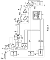
- FIG. 1 a schematic diagram of the control and evaluation circuit according to the invention.
- FIG. 1 shows a schematic diagram of the control and evaluation circuit according to the invention.
- the gas to be measured may be co-located with other gases in a cuvette 2. Pneumatic connections on the cuvette allow gas exchange in the cuvette 2.
- Light in the region of an absorption line of the gas to be measured is transmitted through a distributed feedback (DFB) semiconductor laser 1 ) generated. Transmitted light is converted by a photodiode 3 into an electric current.
- a current-to-voltage converter 4 converts the current supplied by the photodiode 3 into a voltage. It is known to those skilled in the art that a current-to-voltage converter 4 may include an operational amplifier fed back through a resistor and, if necessary, an inverter. The output signal of the current-voltage converter 4 is referred to as the transmission signal 21.
- a subtracter 5 subtracts the transmission signal 21 from a reference signal 20.
- the subtractor supplies a difference signal which is fed to an analog-to-digital converter 6.
- the analog-to-digital converter 6 samples at a frequency of 5 to 10 kHz.
- the subtracter 5 may have an offset adjustment 19 in order to optimally use the dynamic range of the analog-to-digital converter 6 and to keep the required resolution and thus the costs of the analog-to-digital converter 6 low.
- the digital output signal of the analog-to-digital converter 6 can be supplied to a computer 7 or a microprocessor.
- the computer 7 or a microprocessor generates a digital control signal, which is supplied to both the address inputs of the memory 8, as well as the digital-to-analog converter 10.
- the control signal has, for example, a periodic, in particular symmetrical, sawtooth time course and a frequency of 5 Hz.
- the digital-to-analog converter 10 generates from the digital control signal an analog control signal to which the differential amplifier 11 in cooperation with the resistors 12 and 13 a first offset added.
- This first offset roughly matches the semiconductor laser 1 to the absorption line to be measured, so that the semiconductor laser 1 at the minimum output voltage of the digital-to-analog converter 10 light with a frequency above the absorption line and at maximum output voltage of the digital-to-analog converter 10 generates light at a frequency below the absorption line. It is also possible to set the first offset so that, in the case of a control signal equal to the arithmetic mean of minimum and maximum control signal, laser light is generated whose frequency corresponds to the maximum of the absorption line. In this way, the dynamics of the digital-to-analog converter 10 is used optimally. Moreover, the differential amplifier 11 also assumes the function of a power amplifier, so that, in particular, sufficient current is made available for the semiconductor laser 1. The current through the semiconductor laser is also referred to as a drive signal 17.
- this compensation is effected by the memory 8.
- suitable values are stored which correspond to the transmission signal 21 at a zero concentration of the gas to be measured, so that the difference signal at the output of the subtractor 5 is as zero as possible.
- Zero concentration can be understood as the concentration that the gas to be measured has in the ambient air. This concentration is not zero, in particular for the gases N 2 and O 2 . Even with CO 2 , it may be necessary to consider the approximately 0.04% share in the air. This definition of zero concentration allows easy calibration of the device in the ambient air. Alternatively, a gas cylinder with a gas mixture of known composition or a calibration cuvette with an enclosed test gas can also be used for the calibration.
- the semiconductor laser 1 (manufacturer: Nanoplus GmbH, serial number 350 / 10-23) is mounted in a TO5 housing by means of a mounts.
- the mount includes a Peltier element 14 and a thermistor 15. Therefore, the Peltier element 14 and the housing of the semiconductor laser 1 are in thermal contact 24, which in the FIG. 1 is shown by a dashed line.
- the Peltier element is driven by a driver 16.
- In the in FIG. 1 illustrated embodiment includes the Computer 7 a feedback loop from the thermistor 15 via the driver 16 to the Peltier element 14, so that the temperature of the mounts is kept largely constant and thus in particular unaffected by ambient temperature fluctuations.
- the temperature of the semiconductor laser 1 itself deviates more or less from the temperature of the mounts depending on the height of the control signal.
- any conventional memory module can be used as the memory 8.
- pure ROM Read Only Memory
- Writable, non-volatile memories such as EEPROMs (Electrically Erasable Programmable ROM) are well suited.
- EEPROMs Electrical Erasable Programmable ROM
- FIG. 1 In the embodiment shown, even a RAM (random access memory) is used, into which the memory cells are rewritten each time the device is switched on (booting) via the data line 22.
- a computer 7 has a nonvolatile memory such as a hard disk.
- the data line 22 allows recalibration.
- the evaluation of the difference signal is performed by integration over the n-times passing through an absorption line, where n is a natural number (1, 2, 3, ...) and you get an integral signal.
- n is a natural number (1, 2, 3, ...)
- Each falling and each rising edge of the symmetrical, sawtooth-shaped control signal corresponds to passing through the absorption line. It is thus integrated over a time that takes one or more rising and / or falling edges of the control signal.
- This can be done analogously by an integrator or digitally by summing the samples supplied by the analog-to-digital converter 6.
- the latter is in the in FIG. 1 realized embodiment illustrated.
- the integration or summation of the noise is pressed to an acceptable level.
- the integral signal has a good proportionality to the gas concentration, more precisely to the deviation of the gas concentration from the zero concentration.
- the difference signal will fluctuate at least between two values corresponding to ⁇ 1/2 bit of the resolution of the digital-to-analog converters 9 and 10.
- the two values may depend on the level of the digital control signal due to the non-linear characteristic of the semiconductor laser 1.
- the accuracy can be improved by otherwise the same parameters stored in the memory 8 values be calculated so that the integral signal as possible only varies by a value corresponding to ⁇ 1/2-bit resolution of the digital-to-analog converter 9 and 10.
- FIG. 1 shown embodiment used only for measuring the O 2 concentration at a wavelength of 760.26 nm. It is envisaged to determine concentrations of the following gases: CO, O 2 , CO 2 , C 2 H 2 , CH 4 , He, SF 6 and NO.
Landscapes
- Physics & Mathematics (AREA)
- Spectroscopy & Molecular Physics (AREA)
- General Physics & Mathematics (AREA)
- General Health & Medical Sciences (AREA)
- Life Sciences & Earth Sciences (AREA)
- Chemical & Material Sciences (AREA)
- Analytical Chemistry (AREA)
- Biochemistry (AREA)
- Health & Medical Sciences (AREA)
- Immunology (AREA)
- Pathology (AREA)
- Optics & Photonics (AREA)
- Engineering & Computer Science (AREA)
- Mathematical Physics (AREA)
- Theoretical Computer Science (AREA)
- Investigating Or Analysing Materials By Optical Means (AREA)
Claims (11)
- Circuit de commande et d'évaluation pour une diode laser (1) et une photodiode (3) pour déterminer la concentration d'un gaz, la diode laser étant adaptée pour produire de la lumière dans la plage d'une ligne d'absorption du gaz, avec :un pilote (10, 11, 12, 13) pour produire un courant (17) pour la diode laser (1), le pilote comportant un premier convertisseur numérique-analogique (10) convertissant en analogique un signal de commande numérique (23) pour produire le courant (17) ;un module (8, 9) pour produire un signal de référence (20) ; etun soustracteur (5) pour soustraire le signal de référence (20) au signal (21) fourni par la photodiode;caractérisé en ce que :le module pour produire un signal de référence (20) comprend en outre:une mémoire numérique (8) pour mémoriser une courbe caractéristique, la courbe caractéristique étant sélectionnée de telle sorte qu'en cas de concentration nulle du gaz, un signal différentiel est nul à la sortie du soustracteur (5) pour toutes les valeurs du signal de commande (23) se produisant pendant le fonctionnement du circuit, la mémoire numérique (8) étant reliée électriquement à l'entrée du premier convertisseur numérique-analogique (10), de sorte que le signal de commande numérique (23) est également amené à la mémoire numérique (8) en fonctionnement ;un deuxième convertisseur numérique-analogique (9) est relié électriquement de telle sorte à la mémoire numérique (8) que le deuxième convertisseur numérique-analogique (9) tire de la mémoire numérique (8) les valeurs numériques collectées et que le deuxième convertisseur numérique-analogique (9) convertit les valeurs obtenues en signal de référence (20).
- Circuit selon la revendication 1, caractérisé en ce que le pilote comprend en outre un additionneur (11, 12, 13) relié électriquement de telle sorte au premier convertisseur numérique-analogique (10) que le signal de sortie analogique du premier convertisseur numérique-analogique (10) est amené à l'additionneur (11, 12,13) et que l'additionneur (11, 12, 13) peut ajouter au signal de sortie analogique du premier convertisseur numérique-analogique (10) un premier décalage constant, la sortie de l'additionneur (11, 12, 13) pouvant être reliée à la diode laser (1).
- Circuit selon la revendication 2, caractérisé en ce que les lignes d'adresse de la mémoire numérique (8) sont reliées électriquement aux entrées numériques du premier convertisseur numérique-analogique (10).
- Circuit selon la revendication 2 ou 3, caractérisé en ce qu'un microprocesseur (7) est relié aux entrées numériques du premier convertisseur numérique-analogique (10) et peut appliquer au niveau de celui-ci un signal en dents de scie symétrique.
- Circuit selon l'une quelconque des revendications précédentes, caractérisé en outre par un intégrateur (6, 7) relié électriquement à la sortie du soustracteur (5), l'intégrateur étant adapté pour intégrer le signal de sortie du soustracteur (5) soit sur une période du courant (17) soit sur la durée allant d'un minimum à un maximum du courant (17) soit sur la durée allant d'un maximum à un minimum du courant (17).
- Appareil de mesure pour déterminer la concentration d'un gaz avec :une cuvette (2), contenant le gaz ;une diode laser (1) à fréquences d'accord pour produire de la lumière dans la plage d'une ligne d'absorption du gaz ;une photodiode (3) pour détecter la lumière transmise par le gaz contenu dans la cuvette (2) ; etun circuit selon l'une quelconque des revendications précédentes, relié électriquement à la diode laser (1) et à la photodiode (3).
- Procédé pour mesurer la concentration d'un gaz avec :conversion analogique d'un signal de commande numérique (23) dans un premier convertisseur numérique-analogique (10) pour produire un courant (17) pour une diode laser (1);production de lumière dans la diode laser (1) dans une ligne d'absorption du gaz, la longueur d'onde dépendant de la lumière produite par le courant (17) et l'intensité de la lumière produite dépendant également du courant (17) ;mesure de la lumière transmise à travers une région (2) dans l'espace le gaz se trouvant dans cette région dans l'espace, un signal de transmission (21) étant produit à travers elle ; etsoustraction d'un signal de référence (20) à un signal de transmission (21) par le biais d'un soustracteur analogique (5), pour obtenir un signal différentiel;caractérisé par :amenée du signal de commande numérique (23) à une mémoire numérique (8) ;collecte d'une représentation numérique du signal de référence (20) hors de la mémoire numérique (8) mise à jour, la représentation numérique du signal de référence (20) étant associée au signal de commande numérique (23) et appartenant à une courbe caractéristique ;la mémoire numérique (8) mémorisant la courbe caractéristique, la courbe caractéristique étant sélectionnée de telle sorte qu'en cas de concentration nulle du gaz pour toutes les valeurs du signal de commande (23) se produisant, le signal différentiel est nul; etconversion analogique de la représentation numérique du signal de référence (20) dans un deuxième convertisseur numérique-analogique (9), pour obtenir le signal de référence (20).
- Procédé selon la revendication 7, caractérisé en outre par:addition analogique (11, 12, 13) d'un premier décalage constant à un signal de sortie analogique d'un premier convertisseur numérique-analogique (10), pour obtenir le courant (17) servant à commander la diode laser (1) en vue de produire la lumière.
- Procédé selon la revendication 8, caractérisé en outre par:amenée du signal de commande numérique (23) sur les lignes d'adresse jusqu'à la mémoire numérique (8) et sur les entrées numériques du premier convertisseur numérique-analogique (10).
- Procédé selon la revendication 8 ou 9, caractérisé en outre par:production d'un signal en dents de scie symétrique par le biais d'un microprocesseur (7) au niveau des entrées numériques du premier convertisseur numérique-analogique (10).
- Procédé selon l'une quelconque des revendications 8 à 10, caractérisé en outre par :intégration (6, 7) du signal différentiel soit sur une période du courant (17) soit sur la durée allant d'un minimum à un maximum du courant (17) soit sur la durée allant d'un maximum à un minimum du courant (17).
Applications Claiming Priority (2)
| Application Number | Priority Date | Filing Date | Title |
|---|---|---|---|
| DE102009018620A DE102009018620A1 (de) | 2009-04-27 | 2009-04-27 | Ansteuer- und Auswerteschaltung, Messgerät sowie Verfahren zum Messen der Konzentration eines Gases |
| PCT/DE2010/050018 WO2010124685A2 (fr) | 2009-04-27 | 2010-04-14 | Circuit de commande et d'évaluation, appareil de mesure, et procédé pour mesurer la concentration d'un gaz |
Publications (2)
| Publication Number | Publication Date |
|---|---|
| EP2425229A2 EP2425229A2 (fr) | 2012-03-07 |
| EP2425229B1 true EP2425229B1 (fr) | 2016-08-31 |
Family
ID=42635225
Family Applications (1)
| Application Number | Title | Priority Date | Filing Date |
|---|---|---|---|
| EP10722567.4A Not-in-force EP2425229B1 (fr) | 2009-04-27 | 2010-04-14 | Circuit de commande et d'évaluation, appareil de mesure, et procédé pour mesurer la concentration d'un gaz |
Country Status (5)
| Country | Link |
|---|---|
| US (1) | US8736842B2 (fr) |
| EP (1) | EP2425229B1 (fr) |
| DE (1) | DE102009018620A1 (fr) |
| ES (1) | ES2599982T3 (fr) |
| WO (1) | WO2010124685A2 (fr) |
Families Citing this family (2)
| Publication number | Priority date | Publication date | Assignee | Title |
|---|---|---|---|---|
| PL2892920T3 (pl) | 2012-09-07 | 2020-08-24 | INSERM (Institut National de la Santé et de la Recherche Médicale) | Peptydy hamujące pochodzące z receptora aktywującego wykazującego ekspresję na podobnym do trem transkrypcie 1 (tlt-1) komórek szpikowych-1 (trem-1) i ich zastosowania |
| CN114460023B (zh) * | 2022-04-14 | 2022-08-05 | 华电智控(北京)技术有限公司 | 一种用于同时测量多种气体浓度的检测方法、系统和装置 |
Family Cites Families (14)
| Publication number | Priority date | Publication date | Assignee | Title |
|---|---|---|---|---|
| DE3627876A1 (de) * | 1986-08-16 | 1988-02-25 | Felten & Guilleaume Energie | Verfahren und einrichtung zum messen der gaskonzentration in einem gasgemisch |
| US5184017A (en) * | 1989-09-12 | 1993-02-02 | Sensors, Inc. | Method and apparatus for detecting a component gas in a sample |
| DE4122572A1 (de) * | 1991-07-08 | 1993-01-14 | Draegerwerk Ag | Verfahren zum betrieb einer laserdiode |
| US5448071A (en) | 1993-04-16 | 1995-09-05 | Bruce W. McCaul | Gas spectroscopy |
| JP3381755B2 (ja) * | 1994-10-11 | 2003-03-04 | セイコーエプソン株式会社 | 画像の粒状性を減らすための改良された適応性のあるフィルタリングおよび閾値設定の方法及び装置 |
| US5818578A (en) * | 1995-10-10 | 1998-10-06 | American Air Liquide Inc. | Polygonal planar multipass cell, system and apparatus including same, and method of use |
| US6091504A (en) * | 1998-05-21 | 2000-07-18 | Square One Technology, Inc. | Method and apparatus for measuring gas concentration using a semiconductor laser |
| DE19962178A1 (de) | 1999-12-22 | 2001-06-28 | Siemens Ag | Verfahren zur Signalbearbeitung in der Laserspektroskopie |
| EP1475618B1 (fr) * | 2003-05-09 | 2008-12-10 | Siemens Aktiengesellschaft | Méthode et système de spectroscopie à modulation de longueur d'onde |
| GB2412728A (en) | 2004-04-02 | 2005-10-05 | Lee Paul Richman | High integrity gas detector |
| US20060044562A1 (en) * | 2004-08-25 | 2006-03-02 | Norsk Elektro Optikk As | Gas monitor |
| DE102005055938A1 (de) * | 2004-12-20 | 2006-06-29 | Heidelberger Druckmaschinen Ag | Vorrichtung und Verfahren zum Erkennen von Feuchtigkeit in einem Druckplattenbelichter |
| ES2455995T3 (es) | 2005-10-10 | 2014-04-21 | Carefusion Germany 234 Gmbh | Cabezal de medición para instrumentos de diagnóstico y método |
| WO2008079032A2 (fr) * | 2006-12-22 | 2008-07-03 | Photonic Innovations Limited | Détecteur de gaz |
-
2009
- 2009-04-27 DE DE102009018620A patent/DE102009018620A1/de not_active Withdrawn
-
2010
- 2010-04-14 EP EP10722567.4A patent/EP2425229B1/fr not_active Not-in-force
- 2010-04-14 WO PCT/DE2010/050018 patent/WO2010124685A2/fr not_active Ceased
- 2010-04-14 ES ES10722567.4T patent/ES2599982T3/es active Active
- 2010-04-14 US US13/266,610 patent/US8736842B2/en active Active
Also Published As
| Publication number | Publication date |
|---|---|
| WO2010124685A2 (fr) | 2010-11-04 |
| US8736842B2 (en) | 2014-05-27 |
| EP2425229A2 (fr) | 2012-03-07 |
| DE102009018620A1 (de) | 2010-10-28 |
| WO2010124685A3 (fr) | 2011-03-03 |
| ES2599982T3 (es) | 2017-02-06 |
| US20120281220A1 (en) | 2012-11-08 |
Similar Documents
| Publication | Publication Date | Title |
|---|---|---|
| DE19840345B4 (de) | Verfahren und Vorrichtung zum quantitativen Aufspüren eines vorgegebenen Gases | |
| EP3559634B1 (fr) | Procédé de correction de la longueur d'onde et de la gamme d'accord d'un spectromètre à laser | |
| WO2000073768A2 (fr) | Dispositif de capteur de gaz | |
| EP2803975A1 (fr) | Procédé destiné à la spectroscopie laser de gaz | |
| EP1108206A1 (fr) | Dispositif et procede photometriques permettant de determiner le pouvoir calorifique d'un gaz d'essai | |
| DE102013202289B4 (de) | Verfahren und Anordnung zur Ansteuerung einer wellenlängendurchstimmbaren Laserdiode in einem Spektrometer | |
| DE4204126A1 (de) | Verfahren und vorrichtung zur steuerung der frequenz und der ausgangsleistung eines abstimmbaren diodenlasers | |
| EP2425229B1 (fr) | Circuit de commande et d'évaluation, appareil de mesure, et procédé pour mesurer la concentration d'un gaz | |
| DE10002196A1 (de) | Methode zur Positionsregelung von Drehspiegeln mittels einer optischen Spiegelpositionsbestimmung | |
| EP3633352B1 (fr) | Procédé et dispositif de référencement relatif d'un gaz cible dans un système de mesure optique pour la spectroscopie laser | |
| DE102013201459B4 (de) | Verfahren zur Messung der Konzentration einer Gaskomponente in einem Messgas | |
| EP2848918B1 (fr) | Analyseur de gaz | |
| DE102011080086A1 (de) | Verfahren zur Messung der Konzentration einer Gaskomponente in einem Messgas | |
| DE69712053T2 (de) | Gegen umwelteinflüsse unempfindlicher optischer sensor mit verbesserter störsignalunterdrückung | |
| DE102004025448A1 (de) | Verfahren zum Messen eines Spektrums einer Messprobe mittels eines Infrarot-Spektrometers und derartiges Infrarot-Spektrometer | |
| EP0419525B1 (fr) | Dispositif pour mesurer la puissance de rayonnement de lasers | |
| DE69807844T2 (de) | Gerät zur messung des sauerstottgehaltes im einem gas | |
| EP3816609B1 (fr) | Dispositif et procédé de détection à distance d'un gaz cible | |
| WO2015039936A1 (fr) | Procédé et analyseur de gaz permettant de mesurer la concentration d'un composant gazeux dans un gaz de mesure | |
| EP1063518B1 (fr) | Appareil pour analyser un échantillon gazeux par l'absorption d'infrarouge | |
| EP2455733A1 (fr) | Procédé et agencement de mesure pour la spectroscopie à modulation de longueurs d'onde | |
| EP3364169B1 (fr) | Analyseur de gaz de procédé | |
| DE68923966T2 (de) | Schaltung zur steuerung des einstellungspunktes in einer infrarot-gasanalysiervorrichtung. | |
| DE102010006770A1 (de) | Verfahren zur Bestimmung von Strömungsgeschwindigkeiten in mit Partikeln versetzten Fluiden mittels Doppler-Global-Velozimeter | |
| DE3830834C2 (fr) |
Legal Events
| Date | Code | Title | Description |
|---|---|---|---|
| PUAI | Public reference made under article 153(3) epc to a published international application that has entered the european phase |
Free format text: ORIGINAL CODE: 0009012 |
|
| 17P | Request for examination filed |
Effective date: 20111013 |
|
| AK | Designated contracting states |
Kind code of ref document: A2 Designated state(s): AT BE BG CH CY CZ DE DK EE ES FI FR GB GR HR HU IE IS IT LI LT LU LV MC MK MT NL NO PL PT RO SE SI SK SM TR |
|
| RIN1 | Information on inventor provided before grant (corrected) |
Inventor name: SCHERER, HELMUT Inventor name: SCHRADER, DIETER Inventor name: MENNINGER, STEFAN |
|
| DAX | Request for extension of the european patent (deleted) | ||
| 17Q | First examination report despatched |
Effective date: 20141103 |
|
| GRAP | Despatch of communication of intention to grant a patent |
Free format text: ORIGINAL CODE: EPIDOSNIGR1 |
|
| INTG | Intention to grant announced |
Effective date: 20160324 |
|
| RIN1 | Information on inventor provided before grant (corrected) |
Inventor name: SCHERER, HELMUT Inventor name: MENNINGER, STEFAN Inventor name: SCHRADER, DIETER |
|
| GRAS | Grant fee paid |
Free format text: ORIGINAL CODE: EPIDOSNIGR3 |
|
| GRAA | (expected) grant |
Free format text: ORIGINAL CODE: 0009210 |
|
| AK | Designated contracting states |
Kind code of ref document: B1 Designated state(s): AT BE BG CH CY CZ DE DK EE ES FI FR GB GR HR HU IE IS IT LI LT LU LV MC MK MT NL NO PL PT RO SE SI SK SM TR |
|
| REG | Reference to a national code |
Ref country code: CH Ref legal event code: EP Ref country code: GB Ref legal event code: FG4D Free format text: NOT ENGLISH |
|
| REG | Reference to a national code |
Ref country code: IE Ref legal event code: FG4D Free format text: LANGUAGE OF EP DOCUMENT: GERMAN |
|
| REG | Reference to a national code |
Ref country code: DE Ref legal event code: R096 Ref document number: 502010012301 Country of ref document: DE |
|
| REG | Reference to a national code |
Ref country code: AT Ref legal event code: REF Ref document number: 825414 Country of ref document: AT Kind code of ref document: T Effective date: 20161015 |
|
| REG | Reference to a national code |
Ref country code: LT Ref legal event code: MG4D |
|
| REG | Reference to a national code |
Ref country code: NL Ref legal event code: MP Effective date: 20160831 |
|
| PG25 | Lapsed in a contracting state [announced via postgrant information from national office to epo] |
Ref country code: LT Free format text: LAPSE BECAUSE OF FAILURE TO SUBMIT A TRANSLATION OF THE DESCRIPTION OR TO PAY THE FEE WITHIN THE PRESCRIBED TIME-LIMIT Effective date: 20160831 Ref country code: NO Free format text: LAPSE BECAUSE OF FAILURE TO SUBMIT A TRANSLATION OF THE DESCRIPTION OR TO PAY THE FEE WITHIN THE PRESCRIBED TIME-LIMIT Effective date: 20161130 Ref country code: FI Free format text: LAPSE BECAUSE OF FAILURE TO SUBMIT A TRANSLATION OF THE DESCRIPTION OR TO PAY THE FEE WITHIN THE PRESCRIBED TIME-LIMIT Effective date: 20160831 Ref country code: HR Free format text: LAPSE BECAUSE OF FAILURE TO SUBMIT A TRANSLATION OF THE DESCRIPTION OR TO PAY THE FEE WITHIN THE PRESCRIBED TIME-LIMIT Effective date: 20160831 |
|
| REG | Reference to a national code |
Ref country code: ES Ref legal event code: FG2A Ref document number: 2599982 Country of ref document: ES Kind code of ref document: T3 Effective date: 20170206 |
|
| PG25 | Lapsed in a contracting state [announced via postgrant information from national office to epo] |
Ref country code: NL Free format text: LAPSE BECAUSE OF FAILURE TO SUBMIT A TRANSLATION OF THE DESCRIPTION OR TO PAY THE FEE WITHIN THE PRESCRIBED TIME-LIMIT Effective date: 20160831 Ref country code: GR Free format text: LAPSE BECAUSE OF FAILURE TO SUBMIT A TRANSLATION OF THE DESCRIPTION OR TO PAY THE FEE WITHIN THE PRESCRIBED TIME-LIMIT Effective date: 20161201 Ref country code: SE Free format text: LAPSE BECAUSE OF FAILURE TO SUBMIT A TRANSLATION OF THE DESCRIPTION OR TO PAY THE FEE WITHIN THE PRESCRIBED TIME-LIMIT Effective date: 20160831 Ref country code: LV Free format text: LAPSE BECAUSE OF FAILURE TO SUBMIT A TRANSLATION OF THE DESCRIPTION OR TO PAY THE FEE WITHIN THE PRESCRIBED TIME-LIMIT Effective date: 20160831 |
|
| REG | Reference to a national code |
Ref country code: FR Ref legal event code: PLFP Year of fee payment: 8 |
|
| PG25 | Lapsed in a contracting state [announced via postgrant information from national office to epo] |
Ref country code: RO Free format text: LAPSE BECAUSE OF FAILURE TO SUBMIT A TRANSLATION OF THE DESCRIPTION OR TO PAY THE FEE WITHIN THE PRESCRIBED TIME-LIMIT Effective date: 20160831 Ref country code: EE Free format text: LAPSE BECAUSE OF FAILURE TO SUBMIT A TRANSLATION OF THE DESCRIPTION OR TO PAY THE FEE WITHIN THE PRESCRIBED TIME-LIMIT Effective date: 20160831 |
|
| PG25 | Lapsed in a contracting state [announced via postgrant information from national office to epo] |
Ref country code: CZ Free format text: LAPSE BECAUSE OF FAILURE TO SUBMIT A TRANSLATION OF THE DESCRIPTION OR TO PAY THE FEE WITHIN THE PRESCRIBED TIME-LIMIT Effective date: 20160831 Ref country code: SK Free format text: LAPSE BECAUSE OF FAILURE TO SUBMIT A TRANSLATION OF THE DESCRIPTION OR TO PAY THE FEE WITHIN THE PRESCRIBED TIME-LIMIT Effective date: 20160831 Ref country code: PT Free format text: LAPSE BECAUSE OF FAILURE TO SUBMIT A TRANSLATION OF THE DESCRIPTION OR TO PAY THE FEE WITHIN THE PRESCRIBED TIME-LIMIT Effective date: 20170102 Ref country code: PL Free format text: LAPSE BECAUSE OF FAILURE TO SUBMIT A TRANSLATION OF THE DESCRIPTION OR TO PAY THE FEE WITHIN THE PRESCRIBED TIME-LIMIT Effective date: 20160831 Ref country code: SM Free format text: LAPSE BECAUSE OF FAILURE TO SUBMIT A TRANSLATION OF THE DESCRIPTION OR TO PAY THE FEE WITHIN THE PRESCRIBED TIME-LIMIT Effective date: 20160831 Ref country code: DK Free format text: LAPSE BECAUSE OF FAILURE TO SUBMIT A TRANSLATION OF THE DESCRIPTION OR TO PAY THE FEE WITHIN THE PRESCRIBED TIME-LIMIT Effective date: 20160831 Ref country code: BG Free format text: LAPSE BECAUSE OF FAILURE TO SUBMIT A TRANSLATION OF THE DESCRIPTION OR TO PAY THE FEE WITHIN THE PRESCRIBED TIME-LIMIT Effective date: 20161130 |
|
| REG | Reference to a national code |
Ref country code: DE Ref legal event code: R097 Ref document number: 502010012301 Country of ref document: DE |
|
| PLBE | No opposition filed within time limit |
Free format text: ORIGINAL CODE: 0009261 |
|
| STAA | Information on the status of an ep patent application or granted ep patent |
Free format text: STATUS: NO OPPOSITION FILED WITHIN TIME LIMIT |
|
| 26N | No opposition filed |
Effective date: 20170601 |
|
| PG25 | Lapsed in a contracting state [announced via postgrant information from national office to epo] |
Ref country code: SI Free format text: LAPSE BECAUSE OF FAILURE TO SUBMIT A TRANSLATION OF THE DESCRIPTION OR TO PAY THE FEE WITHIN THE PRESCRIBED TIME-LIMIT Effective date: 20160831 |
|
| REG | Reference to a national code |
Ref country code: CH Ref legal event code: PL |
|
| REG | Reference to a national code |
Ref country code: IE Ref legal event code: MM4A |
|
| PG25 | Lapsed in a contracting state [announced via postgrant information from national office to epo] |
Ref country code: MC Free format text: LAPSE BECAUSE OF FAILURE TO SUBMIT A TRANSLATION OF THE DESCRIPTION OR TO PAY THE FEE WITHIN THE PRESCRIBED TIME-LIMIT Effective date: 20160831 |
|
| PG25 | Lapsed in a contracting state [announced via postgrant information from national office to epo] |
Ref country code: LI Free format text: LAPSE BECAUSE OF NON-PAYMENT OF DUE FEES Effective date: 20170430 Ref country code: CH Free format text: LAPSE BECAUSE OF NON-PAYMENT OF DUE FEES Effective date: 20170430 Ref country code: LU Free format text: LAPSE BECAUSE OF NON-PAYMENT OF DUE FEES Effective date: 20170414 |
|
| REG | Reference to a national code |
Ref country code: BE Ref legal event code: MM Effective date: 20170430 |
|
| REG | Reference to a national code |
Ref country code: FR Ref legal event code: PLFP Year of fee payment: 9 |
|
| PG25 | Lapsed in a contracting state [announced via postgrant information from national office to epo] |
Ref country code: IE Free format text: LAPSE BECAUSE OF NON-PAYMENT OF DUE FEES Effective date: 20170414 |
|
| PG25 | Lapsed in a contracting state [announced via postgrant information from national office to epo] |
Ref country code: BE Free format text: LAPSE BECAUSE OF NON-PAYMENT OF DUE FEES Effective date: 20170430 |
|
| REG | Reference to a national code |
Ref country code: AT Ref legal event code: MM01 Ref document number: 825414 Country of ref document: AT Kind code of ref document: T Effective date: 20170414 |
|
| PG25 | Lapsed in a contracting state [announced via postgrant information from national office to epo] |
Ref country code: AT Free format text: LAPSE BECAUSE OF NON-PAYMENT OF DUE FEES Effective date: 20170414 |
|
| PG25 | Lapsed in a contracting state [announced via postgrant information from national office to epo] |
Ref country code: MT Free format text: LAPSE BECAUSE OF FAILURE TO SUBMIT A TRANSLATION OF THE DESCRIPTION OR TO PAY THE FEE WITHIN THE PRESCRIBED TIME-LIMIT Effective date: 20160831 |
|
| PG25 | Lapsed in a contracting state [announced via postgrant information from national office to epo] |
Ref country code: HU Free format text: LAPSE BECAUSE OF FAILURE TO SUBMIT A TRANSLATION OF THE DESCRIPTION OR TO PAY THE FEE WITHIN THE PRESCRIBED TIME-LIMIT; INVALID AB INITIO Effective date: 20100414 |
|
| PG25 | Lapsed in a contracting state [announced via postgrant information from national office to epo] |
Ref country code: CY Free format text: LAPSE BECAUSE OF NON-PAYMENT OF DUE FEES Effective date: 20160831 |
|
| PG25 | Lapsed in a contracting state [announced via postgrant information from national office to epo] |
Ref country code: MK Free format text: LAPSE BECAUSE OF FAILURE TO SUBMIT A TRANSLATION OF THE DESCRIPTION OR TO PAY THE FEE WITHIN THE PRESCRIBED TIME-LIMIT Effective date: 20160831 |
|
| REG | Reference to a national code |
Ref country code: DE Ref legal event code: R082 Ref document number: 502010012301 Country of ref document: DE Representative=s name: HELLMICH, WOLFGANG, DIPL.-PHYS.UNIV. DR.-ING., DE Ref country code: DE Ref legal event code: R081 Ref document number: 502010012301 Country of ref document: DE Owner name: VYAIRE MEDICAL GMBH, DE Free format text: FORMER OWNER: CAREFUSION GERMANY 234 GMBH, 97204 HOECHBERG, DE |
|
| PG25 | Lapsed in a contracting state [announced via postgrant information from national office to epo] |
Ref country code: TR Free format text: LAPSE BECAUSE OF FAILURE TO SUBMIT A TRANSLATION OF THE DESCRIPTION OR TO PAY THE FEE WITHIN THE PRESCRIBED TIME-LIMIT Effective date: 20160831 |
|
| PG25 | Lapsed in a contracting state [announced via postgrant information from national office to epo] |
Ref country code: IS Free format text: LAPSE BECAUSE OF FAILURE TO SUBMIT A TRANSLATION OF THE DESCRIPTION OR TO PAY THE FEE WITHIN THE PRESCRIBED TIME-LIMIT Effective date: 20161231 |
|
| PGFP | Annual fee paid to national office [announced via postgrant information from national office to epo] |
Ref country code: ES Payment date: 20200511 Year of fee payment: 11 Ref country code: FR Payment date: 20200429 Year of fee payment: 11 |
|
| PGFP | Annual fee paid to national office [announced via postgrant information from national office to epo] |
Ref country code: IT Payment date: 20200424 Year of fee payment: 11 Ref country code: GB Payment date: 20200429 Year of fee payment: 11 |
|
| PGFP | Annual fee paid to national office [announced via postgrant information from national office to epo] |
Ref country code: DE Payment date: 20200629 Year of fee payment: 11 |
|
| REG | Reference to a national code |
Ref country code: DE Ref legal event code: R119 Ref document number: 502010012301 Country of ref document: DE |
|
| GBPC | Gb: european patent ceased through non-payment of renewal fee |
Effective date: 20210414 |
|
| PG25 | Lapsed in a contracting state [announced via postgrant information from national office to epo] |
Ref country code: FR Free format text: LAPSE BECAUSE OF NON-PAYMENT OF DUE FEES Effective date: 20210430 Ref country code: GB Free format text: LAPSE BECAUSE OF NON-PAYMENT OF DUE FEES Effective date: 20210414 Ref country code: DE Free format text: LAPSE BECAUSE OF NON-PAYMENT OF DUE FEES Effective date: 20211103 |
|
| REG | Reference to a national code |
Ref country code: ES Ref legal event code: FD2A Effective date: 20220701 |
|
| PG25 | Lapsed in a contracting state [announced via postgrant information from national office to epo] |
Ref country code: ES Free format text: LAPSE BECAUSE OF NON-PAYMENT OF DUE FEES Effective date: 20210415 |
|
| PG25 | Lapsed in a contracting state [announced via postgrant information from national office to epo] |
Ref country code: IT Free format text: LAPSE BECAUSE OF NON-PAYMENT OF DUE FEES Effective date: 20200414 |
|
| PG25 | Lapsed in a contracting state [announced via postgrant information from national office to epo] |
Ref country code: IT Free format text: LAPSE BECAUSE OF NON-PAYMENT OF DUE FEES Effective date: 20210414 |