EP2425226B1 - Pipettengerät - Google Patents
Pipettengerät Download PDFInfo
- Publication number
- EP2425226B1 EP2425226B1 EP09844122.3A EP09844122A EP2425226B1 EP 2425226 B1 EP2425226 B1 EP 2425226B1 EP 09844122 A EP09844122 A EP 09844122A EP 2425226 B1 EP2425226 B1 EP 2425226B1
- Authority
- EP
- European Patent Office
- Prior art keywords
- pipette
- pipette tip
- instrument
- tip
- installed removable
- Prior art date
- Legal status (The legal status is an assumption and is not a legal conclusion. Google has not performed a legal analysis and makes no representation as to the accuracy of the status listed.)
- Active
Links
Images


Classifications
-
- G—PHYSICS
- G01—MEASURING; TESTING
- G01N—INVESTIGATING OR ANALYSING MATERIALS BY DETERMINING THEIR CHEMICAL OR PHYSICAL PROPERTIES
- G01N15/00—Investigating characteristics of particles; Investigating permeability, pore-volume or surface-area of porous materials
- G01N15/10—Investigating individual particles
- G01N15/1031—Investigating individual particles by measuring electrical or magnetic effects
- G01N15/12—Investigating individual particles by measuring electrical or magnetic effects by observing changes in resistance or impedance across apertures when traversed by individual particles, e.g. by using the Coulter principle
-
- B—PERFORMING OPERATIONS; TRANSPORTING
- B01—PHYSICAL OR CHEMICAL PROCESSES OR APPARATUS IN GENERAL
- B01L—CHEMICAL OR PHYSICAL LABORATORY APPARATUS FOR GENERAL USE
- B01L3/00—Containers or dishes for laboratory use, e.g. laboratory glassware; Droppers
- B01L3/02—Burettes; Pipettes
- B01L3/021—Pipettes, i.e. with only one conduit for withdrawing and redistributing liquids
- B01L3/0217—Pipettes, i.e. with only one conduit for withdrawing and redistributing liquids of the plunger pump type
- B01L3/0237—Details of electronic control, e.g. relating to user interface
-
- B—PERFORMING OPERATIONS; TRANSPORTING
- B01—PHYSICAL OR CHEMICAL PROCESSES OR APPARATUS IN GENERAL
- B01L—CHEMICAL OR PHYSICAL LABORATORY APPARATUS FOR GENERAL USE
- B01L2200/00—Solutions for specific problems relating to chemical or physical laboratory apparatus
- B01L2200/14—Process control and prevention of errors
- B01L2200/141—Preventing contamination, tampering
-
- B—PERFORMING OPERATIONS; TRANSPORTING
- B01—PHYSICAL OR CHEMICAL PROCESSES OR APPARATUS IN GENERAL
- B01L—CHEMICAL OR PHYSICAL LABORATORY APPARATUS FOR GENERAL USE
- B01L2200/00—Solutions for specific problems relating to chemical or physical laboratory apparatus
- B01L2200/14—Process control and prevention of errors
- B01L2200/143—Quality control, feedback systems
- B01L2200/146—Employing pressure sensors
-
- B—PERFORMING OPERATIONS; TRANSPORTING
- B01—PHYSICAL OR CHEMICAL PROCESSES OR APPARATUS IN GENERAL
- B01L—CHEMICAL OR PHYSICAL LABORATORY APPARATUS FOR GENERAL USE
- B01L2400/00—Moving or stopping fluids
- B01L2400/04—Moving fluids with specific forces or mechanical means
- B01L2400/0475—Moving fluids with specific forces or mechanical means specific mechanical means and fluid pressure
- B01L2400/0487—Moving fluids with specific forces or mechanical means specific mechanical means and fluid pressure fluid pressure, pneumatics
-
- G—PHYSICS
- G01—MEASURING; TESTING
- G01N—INVESTIGATING OR ANALYSING MATERIALS BY DETERMINING THEIR CHEMICAL OR PHYSICAL PROPERTIES
- G01N35/00—Automatic analysis not limited to methods or materials provided for in any single one of groups G01N1/00 - G01N33/00; Handling materials therefor
- G01N35/10—Devices for transferring samples or any liquids to, in, or from, the analysis apparatus, e.g. suction devices, injection devices
- G01N2035/1027—General features of the devices
- G01N2035/1048—General features of the devices using the transfer device for another function
- G01N2035/1062—General features of the devices using the transfer device for another function for testing the liquid while it is in the transfer device
Definitions
- This invention relates to devices that may be used repetitively to extract a precise volume of fluid from a bulk container of fluid.
- a pipette is arguably one of the most commonly used hand tools in a wet chemistry laboratory environment. Typically, a pipette is used to extract one or more sub-sample from a bulk container of fluid. (This disclosure will generally make specific reference to a pipette tip, in an attempt to distinguish the removable tip over the pipette instrument itself).
- Pipettes are commercially available in various configurations that may be used repetitively to extract and dispense precisely metered quantities of fluid. Commercially available pipettes include both hand-held models and bench-top models that may be variously automated, or robotically controlled.
- WO2009/045343 discloses a hand-held pipette instrument, the pipette instrument comprising:
- a pipettor that include sensors for sensing parameters useful for fluid handling.
- a pipettor can include an integral impedance sensor useful for counting particles and/or calculating particle concentration.
- the invention provides a hand-held pipette instrument as specified in claim 1.
- the pipette instrument may be used to interrogate particles in a fluid sample as the sample is extracted from a bulk container of particle-bearing fluid.
- the invention provides a method of particle counting as specified in claim 8.
- the pipette instrument may include a hydrophobic barrier element disposed to resist flow of fluid from an installed pipette tip past the barrier element and further into the pipette instrument.
- a pressure transducer is disposed in communication with the microprocessor to monitor a suction pressure profile delivered to the pipette tip interface.
- the pipette instruments may include a USB port structured to permit communication between the pipette instrument and a remote terminal. It is within contemplation to provide a wireless communication module structured to permit communication between the pipette instrument and a remote terminal.
- Software may be loaded into the memory effective to program the microprocessor to permit the pipette instrument to perform a selected test.
- Preferred pipette instruments include a user control system operable to select a desired mode of operation of the pipette instrument from a plurality of operable modes.
- One user operable control system includes a track wheel, and a start button.
- a track wheel can be disposed to interface for actuation by rolling along a length axis of a finger of a hand that is holding the pipette body such that the wheel is disposed in registration with a distal portion of a user's finger.
- the track wheel may be structured to provide an input to the pipette instrument by permitting a finger to depress the track wheel in a trigger-squeezing motion.
- One operable source of suction includes a surplus vacuum in a reservoir, and a regulator operable to down-regulate that surplus vacuum disposed for action between the reservoir and pipette tip interface effective to place a desired vacuum profile in communication with an installed pipette tip.
- Surplus vacuum may be created by user displacement of a biased element associated with the body.
- Surplus vacuum can also be created with an electric pump.
- a preferred source of suction comprises an electric pump operable under control of the microprocessor directly to generate an actual desired suction profile delivered to the pipette tip interface.
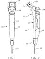
- Pipette 100 includes a generally cylindrical, extended body 102.
- a surface of body 102 is structured to form a palm gripping area 104 and a finger gripping area, generally 106.
- the illustrated pipette 100 includes a plurality of controls forming a system to receive a user input, including button 108, and scroll wheel 110.
- button 108 is disposed for user actuation by a user's thumb during one-handed operation of pipette 100.
- Scroll wheel 1 10 is disposed to fit under a user's finger, such as the pointer finger, and may be actuated by rolling along a length axis of a finger of a hand that is holding the body 100.
- a currently preferred scroll wheel 1 10 is also adapted to receive actuation by depressing the entire wheel with a finger tip, similar to pulling the trigger of a handgun.
- a display device 112 may be included, e.g. to indicate selection choices to a user, and to show data results.
- a distal end of pipette 100 is structured to receive one of a plurality of pipette tips, such as the installed tip 114.
- Pipette tip 114 may be characterized as an instrumented pipette tip, in that provisions are made for the tip 1 14 to cooperate with the pipette 100 to interrogate particles as fluid is inspired through the tip 114.
- instrumented pipette tips that cooperate with a pipette instrument are used once, then discarded.
- a tip interface module, generally 116 may be provided to facilitate regular maintenance of a pipette instrument, such as pipette 100, as will be described in more detail below.
- the body of pipette 100 houses a vacuum pump 120 disposed in-circuit with the button 108 to effect a suction on an installed pipette tip.
- button 108 serves as a familiar interface to a user of a conventional hand-held pipette instrument.
- An air reservoir 122 and pneumatic manifold 124 are used to regulate a pressure profile that is applied over a time increment to a pipette tip, such as tip 114.
- Pressure transducer 126 provides a feedback signal for the control system.
- the solenoid valve 128 is used as a purge valve to terminate a suction applied by the pump and reservoir.
- the control system is orchestrated by a programmable microprocessor and associated memory 130, which can be variously programmed to substantially automatically perform a desired test.
- Software may be loaded into memory effective to program the microprocessor to permit the pipette instrument to perform a selected test.
- the suction system associated with a pipette instrument desirably has an on-board pressure transducer disposed to measure the actual pressure profile that is delivered to a removable pipette tip.
- three types of suction systems have been built and tested: 1) Generate surplus vacuum using a manually actuated air cylinder and down-regulate using a microprocessor controlled proportional valve and pressure transducer. Vent with a solenoid valve. 2) Generate the vacuum as needed using a microprocessor controlled PID loop with a small vacuum pump (on demand) and a pressure transducer. Vent with a solenoid valve. This is the currently preferred embodiment. It is also desirable to include a "reservoir tank" to dampen the applied vacuum, but that is not critical.
- Interrogation electronics are disposed for connection in-circuit with certain installed pipette tips.
- the interrogation electronics are configured to detect and/or interpret Coulter principle phenomena, and/or Stokes shift phenomena, which occur on-board the pipette tip.
- the interrogation electronics are configured to communicate one or more applied signals to the pipette tip, and relay a resulting signal from the pipette tip to the microprocessor for data manipulation and, typically, display of an output on display device 1 12.
- a communication link such as a USB connector 134, wireless transmitter, or other communication device, is provided to facilitate transporting acquired and/or processed test signal data to a remote terminal or storage facility.
- Electrical power is desirably provided by a rechargeable electrical power source, such as a battery pack generally indicated at 136.
- a rechargeable electrical power source such as a battery pack generally indicated at 136.
- the device 100 could be embodied as a corded device that receives power from a plug-in electrical utility, such as a wall socket.
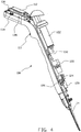
- FIG. 5 illustrates an alternative arrangement for providing a pressure profile to a pipette tip.
- the embodiment generally indicated at 140 includes a vacuum cylinder 142 disposed in fluid circuit with a proportional valve 144 and a pneumatic manifold 124.
- Pressure transducer 126 provides a feedback signal to the microprocessor, which is programmed to apply a desired profile to an installed pipette tip.
- a purge valve 128 is included in operable fluid circuit to release suction at the completion of an applied pressure profile. Tubing stretches that would place the various components in fluid circuit have been omitted for clarity of illustration.
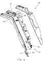
- FIG. 6 illustrates certain desirable details of a currently preferred tip interface, generally indicated at 148.
- a replaceable hydrophobic barrier 150 is carried on removable module 1 16, and resists fluid flow beyond itself and further into the pipette instrument generally indicated at 152. Therefore, inspired fluid is at least substantially retained inside a removable pipette tip.
- the O-ring 154 is disposed to form a seal against a face of an installed pipette tip through which to transmit the applied suction profile.
- a spring 156 may be included to provide a bias to encourage proper and effective seal formation between the O-ring 154 and a cooperating surface of the tip.
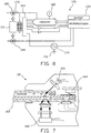
- the pipette portion generally indicated at 160 desirably carries orienting structure effective to facilitate coupling with a removable pipette tip 162.
- An installed tip 162 may be positioned to couple with an optional edge connector 164, effective to place interrogation circuitry into communication with electrodes carried by the tip 162. Therefore, interrogation circuitry may detect and/or interpret Coulter principle phenomena, which occurs on-board the pipette tip as fluid is inspired into the tip 162.
- the installed tip 162 may be positioned between a radiation source 166 and a radiation receiver 168.
- the source 166 and receiver 168 place interrogation circuitry into communication with the pipette tip 162 effective to detect, and/or interpret, Stokes shift phenomena that may occur on-board the pipette tip as fluid is inspired into the tip 162.
- An operable radiation source may include a fiber optic cable, which permits remote disposition of a radiation source (e.g. laser, LED) at a convenient location of a pipette.
- the receiver may include a fiber optic cable arranged to transport a phase-shifted signal to a radiation detector disposed at a convenient remote location. Locating certain components at a remote location facilitates construction of a more slender pipette tip area.
- An operable interrogation circuitry is generally indicated at 170 in FIG. 8 .
- a microprocessor and memory 172 desirably are placed into a cooperating operable relationship with the interrogation circuitry 170.
- One or more electrical signal generator 174 is disposed to apply a signal with reference to ground 176 onto pins, generally 178, of a communication interface for a removable pipette tip 1 14, such as edge connector 164.
- a light source 180 may be included to apply a radiation signal to an interrogation zone of a pipette tip.
- a signal detector, such as ohmmeter 182 and/or light detector 184, is disposed to interrogate corresponding signals received from a tip.
- Electrodes carried by a tip 114 may be provided to form stimulated electrodes to apply a signal to fluid flowing through the tip; interrogation electrodes that return a data signal from the tip to the pipette; and trigger electrodes that may be disposed to indicate the location of a fluid wave-front at certain locations disposed along a conduit through the tip.
- Trigger electrodes can be used, for example, to start and stop a test that is at least partially automated. Electrodes may also be used to provide a continuity signal, for examples: to verify proper installation of a tip in the pipette, or to identify a particular tip and perform a corresponding data collection procedure.
- FIG. 9 illustrates operation of a representative pipette instrument, generally indicated at 210.
- the pipette 210 may sometimes be tethered through a cable 212, such as a USB cable, to a remote data receiver 214, such as a personal computer.
- Test data may be uploaded to the receiver 214 through cable 212, or in certain embodiments, using wireless communication 216.
- a suction pressure profile that starts at about local atmospheric pressure, then ramps to a substantially constant pressure of about 20 inches Of H2O (vacuum) for 2-5 seconds, and then ramps to about 40 inches of H2O (vacuum) for the remainder of the test.
- a ramp event is typically effected substantially as a step change in pressure, within the capability of the equipment.
- either a ramp event, or an entire pressure profile may be structured to apply any function of pressure over any increment of time that is desired in any particular case.
- different pressure profiles may be applied to different pipette tips, such as tips that are used for different tests.
- tips structured to interrogate larger particles may require a different pressure profile than tips structured to interrogate very small particles.
- a flat pressure profile, or substantially constant pressure having any operable magnitude may be applied to obtain workable results for many, if not all, pipette tips.
- FIGs. 10 through 12 are screen shots (histograms) of particle count vs. particle size, and are representative of data that may be obtained and displayed.
- FIG. 10 is a histogram of a particle suspension containing three differently sized latex beads (8, 10, and 15 ⁇ m).
- FIG. 11 illustrates test results of a suspension of one tight distribution of a single population of precision 10 ⁇ m beads.
- FIG. 12 is a histogram of a particle suspension containing a population of cultured malian cells with an average size of about 16 ⁇ m.
- Track wheel can be used (scrolling and/or indexing) to navigate through the menus (i.e., saving files, retrieving files, transferring files, etc.).
- USB cable may be used to recharge the battery and transfer histogram files to a PC.
- a desired particle test is typically selected by a user by way of a control input, typically with the scroll wheel and with reference to one or more menu presented on display device 1 12.
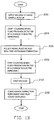
- a pipette tip is installed in a pipette, and the tip is dipped into a bulk container of fluid to be tested. Suction is applied as indicated at step 220.
- a trigger signal obtained from the pipette tip can be used to start data collection, as indicated at step 224.
- the microprocessor processes at least one signal obtained from the tip as fluid is inspired, and generates a real-time histogram, as indicated at step 226.
- a second trigger signal may be used to terminate data collection, as indicated at step 228.
- Applied suction is then terminated, as indicated at step 230. If desired, coincidence correction may be performed on a displayed piece of data, as indicated at step 232.
- the pipette tip is typically discarded after a single use.
- the data signal (differential voltage in the currently preferred embodiment) is obtained from the tip and is amplified immediately. It is then digitized and run through a real time peak finding (or pulse finding) algorithm by the microprocessor.
- peak finding or pulse finding
- peaks over a certain size threshold i.e., voltage threshold
- the corresponding peak voltage is placed in a "bin” that corresponds to particle size.
- bins i.e., individual bars
- the "observed" particle count is the count obtained right off the raw histogram, usually between two lines (i.e., a lower and upper threshold) that can be positioned by the user.
- the observed count is coincidence corrected to obtain the "true” count.
- Observed counts are almost equal to True counts at low particle concentrations.
- a fudge-factor equation may be used to determine True count from Observed counts.
- An operable such equation is presented in the paper " Coincidence correction for electrical-zone (Coulter-counter) particle size analysers" by E.J. Wynn and M. J. Hounslow, Department of Chemical Engineering, University of Cambridge, Pembroke Street, Cambridge CB2 3RA, UK .
- Pipette tips may be calibrated (for coincidence correction) using serial dilutions of latex beads (as per the above-referenced paper).
- the user can ALSO calibrate (this is a different type of calibration) the pipette x-axis (particle size) using solutions of latex beads with a known size. This is a manual process where the user dials in the x-axis to match the known bead size.
- a representative Coulter-style stimulus signal applied to a pipette tip by the interrogation circuitry includes a signal and a ground. It is currently preferred to supply a source and a sink for a constant-current stimulus using one electrode disposed on each side of an interrogation orifice carried by a pipette tip. The key is to pass a measurable signal through the orifice somehow. While currently preferred to apply a constant current, it is also possible to apply a constant voltage, although not ideal. It is currently preferred to use a DC stimulus, but AC is also possible. At least one measurement electrode is required. It is currently preferred to use two (one disposed on each side of the interrogation orifice), in a differential mode.
Landscapes
- Chemical & Material Sciences (AREA)
- Health & Medical Sciences (AREA)
- Chemical Kinetics & Catalysis (AREA)
- Clinical Laboratory Science (AREA)
- Life Sciences & Earth Sciences (AREA)
- Human Computer Interaction (AREA)
- Dispersion Chemistry (AREA)
- Physics & Mathematics (AREA)
- Engineering & Computer Science (AREA)
- Analytical Chemistry (AREA)
- Biochemistry (AREA)
- General Health & Medical Sciences (AREA)
- General Physics & Mathematics (AREA)
- Immunology (AREA)
- Pathology (AREA)
- Sampling And Sample Adjustment (AREA)
- Devices For Use In Laboratory Experiments (AREA)
Claims (8)
- Handpipettengerät (100, 140, 152, 210), wobei das Pipettengerät umfasst:eine installierte entfernbare Pipettenspitze (114, 162); undeinen Körper (102), der trägt:eine Saugquelle (120, 142);eine Pipettenspitzenschnittstelle (148), die dafür ausgelegt ist, um die genannte installierte entfernbare Pipettenspitze (114, 162) zu halten und um die genannte installierte entfernbare Pipettenspitze (114, 162) in Kommunikation mit der genannten Saugquelle (120, 142) zu platzieren; undeine elektrische Energiequelle (136) in betreibbarer Assoziation mit:einem Anzeigefeld (112), das einem Benutzer Informationen visuell präsentieren kann; undeinem Mikroprozessor und einem assoziierten Speicher (130, 172); wobei:
die genannte Pipettenspitzenschnittstelle (148) ferner strukturiert und eingerichtet ist, um die genannte installierte entfernbare Pipettenspitze (114, 162) in Kommunikation mit Abfrageschaltungen (132, 170) anzuordnen, die von dem genannten Körper getragen wird und dafür ausgelegt ist, um ein Eingangssignal von der genannten installierten entfernbaren Pipettenspitze zu empfangen, wobei die genannten Abfrageschaltungen (132, 170) für eine Partikelzählung durch die Detektion von Signalen geeignet sind, welche aus Stokes-Verschiebungsphänomenen resultieren, die in der genannten installierten entfernbaren Pipettenspitze (114, 162) auftreten, und/oder die genannten Abfrageschaltungen (132, 170) für eine Partikelzählung durch die Detektion von Signalen geeignet sind, welche aus Coulter-Prinzip-Phänomenen resultieren, die in der genannten installierten entfernbaren Pipettenspitze (114, 162) auftreten, wobei das Pipettengerät dafür ausgelegt ist, um im Gebrauch zu ermöglichen, dass eine untere Spannungsschwellengrenze und eine obere Spannungsschwellengrenze der detektierten Signale ausgewählt werden, und wobei das Pipettengerät dafür ausgelegt ist, um eine Partikelzählung auf der Basis von Daten zu berechnen, die zwischen den ausgewählten Grenzen gesammelt werden. - Pipettengerät nach Anspruch 1, ferner umfassend ein hydrophobes Barrierenelement (150), das auf einem entfernbaren Spitzenschnittstellenmodul (116) getragen wird und dafür geeignet ist, um einer Fluidströmung von der genannten installierten entfernbaren Pipettenspitze (114, 162) an dem Barrierenelement (150) vorbei und weiter in das genannte Pipettengerät entgegenzuwirken.
- Pipettengerät nach Anspruch 1 oder 2, ferner umfassend:
ein von einem Benutzer bedienbares Steuersystem, das betreibbar ist, um einen gewünschten Betriebsmodus des genannten Pipettengeräts unter einer Vielzahl von Betriebsmodi auszuwählen, wobei das genannte von einem Benutzer bedienbare Steuersystem ein Wählrad (110) umfasst, das angeordnet ist, um eine Schnittstelle zur Betätigung durch Rollen entlang einer Längsachse eines Fingers einer Hand zu bilden, die den genannten Körper hält, und strukturiert ist, um einen Eingang in das genannte Pipetteninstrument zu liefern, indem gestattet wird, dass der genannte Finger auf das genannte Wählrad (110) in einer Auslöserdrückbewegung drückt. - Pipettengerät nach Anspruch 1, 2 oder 3, ferner umfassend:
einen Druckwandler (126), der in Kommunikation mit dem genannten Mikroprozessor (130) steht und angeordnet ist, um ein Saugdruckprofil zu überwachen, das an die genannte Pipettenspitzenschnittstelle (148) geliefert wird. - Pipettengerät nach einem der vorhergehenden Ansprüche, wobei:die genannte Saugquelle ein überschüssiges Vakuum in einem Behälter (142) umfasst; undein Regler (144), der betreibbar ist, um das genannte überschüssige Vakuum abwärts zu regeln, zur Wirkung zwischen dem genannten Behälter (142) und der genannten Pipettenspitzenschnittstelle (148) angeordnet ist, die effektiv ist, um ein gewünschtes Vakuumprofil in Kommunikation mit der genannten installierten entfernbaren Pipettenspitze (114, 162) zu platzieren.
- Pipettengerät nach einem der Ansprüche 1 bis 4, wobei:
die genannte Saugquelle eine elektrische Pumpe (120) umfasst, die unter der Steuerung des genannten Mikroprozessors betreibbar ist, um direkt ein tatsächliches gewünschtes Saugprofil zu erzeugen, das an die genannte Pipettenspitzenschnittstelle (148) geliefert wird. - Pipettengerät nach Anspruch 1, wobei:
ein Handabschnitt (102) des genannten Pipettengeräts dafür ausgelegt ist, um sowohl:ein erstes Signal an die genannte installierte entfernbare Pipettenspitze (114, 162) anzulegen; als auchein zweites Signal von der genannten installierten entfernbaren Pipettenspitze (114, 162) zu empfangen, wobei das genannte zweite Signal von dem genannten ersten Signal verschieden ist. - Verfahren zur Partikelzählung unter Verwendung des Handpipettengeräts nach Anspruch 1, umfassend:Bereitstellen des Handpipettengeräts;Detektieren von Signalen, welche aus Stokes-Verschiebungsphänomenen resultieren, die in der installierten entfernbaren Pipettenspitze (114, 162) auftreten; und/oderDetektieren von Signalen, welche aus Coulter-Prinzip-Phänomenen resultieren, die in der genannten installierten entfernbaren Pipettenspitze (114, 162) auftreten;Auswählen einer unteren Spannungsschwellengrenze und einer oberen Spannungsschwellengrenze der detektierten Signale; undBerechnen einer Partikelzählung auf der Basis von Daten, die zwischen den ausgewählten Grenzen gesammelt werden.
Applications Claiming Priority (1)
| Application Number | Priority Date | Filing Date | Title |
|---|---|---|---|
| PCT/US2009/002564 WO2010126459A1 (en) | 2009-04-27 | 2009-04-27 | Pipette instrument |
Publications (3)
| Publication Number | Publication Date |
|---|---|
| EP2425226A1 EP2425226A1 (de) | 2012-03-07 |
| EP2425226A4 EP2425226A4 (de) | 2016-09-07 |
| EP2425226B1 true EP2425226B1 (de) | 2020-10-07 |
Family
ID=43032405
Family Applications (1)
| Application Number | Title | Priority Date | Filing Date |
|---|---|---|---|
| EP09844122.3A Active EP2425226B1 (de) | 2009-04-27 | 2009-04-27 | Pipettengerät |
Country Status (7)
| Country | Link |
|---|---|
| US (1) | US9470616B2 (de) |
| EP (1) | EP2425226B1 (de) |
| JP (1) | JP5550719B2 (de) |
| CN (1) | CN102414550B (de) |
| ES (1) | ES2835181T3 (de) |
| SG (1) | SG175303A1 (de) |
| WO (1) | WO2010126459A1 (de) |
Families Citing this family (15)
| Publication number | Priority date | Publication date | Assignee | Title |
|---|---|---|---|---|
| US9333502B1 (en) | 2012-09-13 | 2016-05-10 | E. I. Spectra, Llc | Sample-acquiring microfluidic tester |
| CN104117396B (zh) * | 2013-04-26 | 2016-08-10 | 中国科学院化学研究所 | 具有超疏水性的移液枪枪头及其制备方法 |
| US9915614B2 (en) * | 2013-04-26 | 2018-03-13 | Academia Sinica | Microfluidic systems and devices for molecular capture, manipulation, and analysis |
| ES2716898T3 (es) | 2013-10-15 | 2019-06-17 | Ecole Polytechnique Fed Lausanne Epfl | Punta detectora con sensor de impedancia eléctrica |
| WO2015141764A1 (ja) * | 2014-03-20 | 2015-09-24 | 独立行政法人産業技術総合研究所 | ピペット装置及び液体処理システム |
| KR20150115391A (ko) | 2014-04-04 | 2015-10-14 | 쓰리엠 이노베이티브 프로퍼티즈 캄파니 | 피펫 장치 |
| WO2016035180A1 (ja) * | 2014-09-03 | 2016-03-10 | 独立行政法人産業技術総合研究所 | 電動ピペットシステム、電動ピペット及び作業手順表示装置 |
| FR3037825B1 (fr) * | 2015-06-24 | 2017-07-28 | Gilson Sas | Bouton de commande ameliore pour pipette de prelevement |
| JP6842242B2 (ja) * | 2016-03-22 | 2021-03-17 | 株式会社アイカムス・ラボ | 分注システム |
| US11253850B2 (en) | 2016-07-14 | 2022-02-22 | Hewlett-Packard Development Company, L.P. | Pipette dispenser tip utilizing print head |
| US10864515B2 (en) * | 2016-11-11 | 2020-12-15 | Walid Habbal | Automated pipette manipulation system |
| EP3335795B1 (de) | 2016-12-16 | 2019-03-27 | Eppendorf AG | Verfahren zum dosieren von flüssigkeit mittels einer pipette und einer spritze und pipette zum betätigen einer spritze zum dosieren von flüssigkeit |
| CN106622418B (zh) * | 2017-01-31 | 2019-02-05 | 佛山市顺德区罗恩科学仪器有限公司 | 移液器移液参数调节操作方法 |
| CN111655375B (zh) * | 2017-11-30 | 2022-08-23 | 康宁股份有限公司 | 双轴取向的热塑性移液器、其形成方法和设备 |
| WO2020214224A1 (en) * | 2019-04-18 | 2020-10-22 | Siemens Healthcare Diagnostics Inc. | Integrated microfluidic device with pipette adaptation |
Family Cites Families (59)
| Publication number | Priority date | Publication date | Assignee | Title |
|---|---|---|---|---|
| US3910702A (en) * | 1974-02-12 | 1975-10-07 | Particle Technology Inc | Apparatus for detecting particles employing apertured light emitting device |
| US4734261A (en) | 1985-01-29 | 1988-03-29 | Fuji Photo Film Co., Ltd. | Duplex pipette |
| AT391634B (de) * | 1988-05-04 | 1990-11-12 | Avl Verbrennungskraft Messtech | Analysengeraet |
| WO1991001486A1 (en) | 1989-07-24 | 1991-02-07 | Tritech Partners | New and improved sample liquid aspirating and dispensing probe |
| WO1991016675A1 (en) * | 1990-04-06 | 1991-10-31 | Applied Biosystems, Inc. | Automated molecular biology laboratory |
| US5509318A (en) | 1993-10-13 | 1996-04-23 | Manostat Corporation | Memory Mopet |
| DE4427725C2 (de) | 1994-08-05 | 1996-10-24 | Inst Chemo Biosensorik | Meßeinrichtung zur Analyse von Flüssigkeiten |
| US5504011A (en) | 1994-10-21 | 1996-04-02 | International Technidyne Corporation | Portable test apparatus and associated method of performing a blood coagulation test |
| US5432098A (en) | 1994-10-31 | 1995-07-11 | Dynatech Precision Sampling Corporation | Apparatus, and process, for automatically sampling solids and semi-solids materials for analysis |
| US6117394A (en) * | 1996-04-10 | 2000-09-12 | Smith; James C. | Membrane filtered pipette tip |
| JPH10318904A (ja) | 1996-06-10 | 1998-12-04 | Toa Medical Electronics Co Ltd | 粒子画像分析装置およびその分析用プログラムを記録した記録媒体 |
| US6710871B1 (en) | 1997-06-09 | 2004-03-23 | Guava Technologies, Inc. | Method and apparatus for detecting microparticles in fluid samples |
| FI107026B (fi) * | 1998-08-26 | 2001-05-31 | Biohit Oyj | Imulaitteen kärki ja menetelmä nesteen annostelemiseksi imulaitteella |
| JP4101994B2 (ja) | 1999-01-21 | 2008-06-18 | シスメックス株式会社 | 粒子分析装置および自動粒子分析方法 |
| US6299841B1 (en) * | 1999-03-05 | 2001-10-09 | Rainin Instrument Co., Inc. | Bilaterally symmetrical battery powered microprocessor controlled lightweight hand-holdable electronic pipette |
| DE19933458B4 (de) | 1999-07-15 | 2015-08-20 | Eppendorf Ag | Einrichtungen und Systeme zum Handhaben von Flüssigkeitsproben |
| AU4491100A (en) * | 1999-07-21 | 2001-02-13 | Surromed, Inc. | System for microvolume laser scanning cytometry |
| US6244119B1 (en) | 1999-08-03 | 2001-06-12 | Wallac Oy | Multichannel pipette system and pipette tips therefor |
| US6399024B1 (en) | 2000-02-01 | 2002-06-04 | Incyte Genomics, Inc. | Multichannel pipette head |
| WO2002000346A2 (en) | 2000-06-26 | 2002-01-03 | Vistalab Technologies, Inc. | Handheld pipette |
| JP4271835B2 (ja) | 2000-08-18 | 2009-06-03 | アークレイ株式会社 | ピペット装置 |
| CN2462374Y (zh) * | 2001-01-05 | 2001-11-28 | 胡乃钢 | 一种可导电的移液器吸头 |
| CN1368402A (zh) * | 2001-02-07 | 2002-09-11 | 胡乃钢 | 一种带自控装置的移液器 |
| US6982063B2 (en) * | 2001-05-25 | 2006-01-03 | Matrix Technologies Corp | Automated pipetting system |
| US6838278B2 (en) | 2001-10-22 | 2005-01-04 | Midatlantic Diagnostics, Inc. | Device for cell transfer |
| WO2003048786A2 (en) | 2001-11-30 | 2003-06-12 | Bristol-Myers Squibb Company | Pipette configurations and arrays thereof for measuring cellular electrical properties |
| US6702990B1 (en) | 2002-02-05 | 2004-03-09 | The Gel Company | Spot picker |
| US6889557B2 (en) | 2002-02-11 | 2005-05-10 | Bechtel Bwxt Idaho, Llc | Network and topology for identifying, locating and quantifying physical phenomena, systems and methods for employing same |
| US7093507B2 (en) | 2003-05-12 | 2006-08-22 | Bel-Art Products, Inc. | Pipette control arrangement |
| US7396512B2 (en) * | 2003-11-04 | 2008-07-08 | Drummond Scientific Company | Automatic precision non-contact open-loop fluid dispensing |
| US7976793B2 (en) * | 2003-11-27 | 2011-07-12 | Gilson S.A.S. | Electronic pipette |
| WO2005121780A2 (en) * | 2003-12-09 | 2005-12-22 | Board Of Regents, The University Of Texas System | Methods and apparatus for characterizing, measuring, and dispensing fluids |
| WO2005069935A2 (en) * | 2004-01-20 | 2005-08-04 | University Of Medicine And Dentistry Of New Jersey | METHODS FOR MEASURING TRANSFORMING GROWTH FACTOR BETA (TGF-β) RECEPTOR SIGNALING ACTIVITY AND USES THEREOF |
| DE102004003433B4 (de) | 2004-01-21 | 2006-03-23 | Eppendorf Ag | Pipettiervorrichtung mit einer Abwurfeinrichtung für Pipettenspitzen |
| FI20040291A0 (fi) * | 2004-02-25 | 2004-02-25 | Thermo Electron Oy | Elektroninen pipetti |
| DE102004016003B4 (de) * | 2004-04-01 | 2006-05-04 | Eppendorf Ag | Elektronische Pipette |
| US7955865B2 (en) | 2004-06-09 | 2011-06-07 | The University Of British Columbia | Reagent delivery apparatus and methods |
| US7457709B2 (en) * | 2005-12-20 | 2008-11-25 | Beckman Coulter, Inc. | Systems and methods for particle counting |
| US8171778B2 (en) | 2006-05-05 | 2012-05-08 | E I Spectra, LLC | Thin film particle sensor |
| US7520164B1 (en) * | 2006-05-05 | 2009-04-21 | E.I. Spectra, Llc | Thin film particle sensor |
| EP1859868A1 (de) | 2006-05-23 | 2007-11-28 | F.Hoffmann-La Roche Ag | Beheizbare Pipette |
| DE102006024051A1 (de) * | 2006-05-23 | 2007-12-06 | Eppendorf Ag | Elektronische Dosiervorrichtung zum Dosieren von Flüssigkeiten |
| DE102006032859A1 (de) * | 2006-07-14 | 2008-01-17 | Eppendorf Ag | Elektronische Dosiervorrichtung zum Dosieren von Flüssigkeiten |
| US7448287B2 (en) | 2006-10-02 | 2008-11-11 | Palo Alto Research Center Incorporated | Pipette with agitation feature |
| US7835000B2 (en) | 2006-11-03 | 2010-11-16 | Los Alamos National Security, Llc | System and method for measuring particles in a sample stream of a flow cytometer or the like |
| US7794664B2 (en) | 2006-11-16 | 2010-09-14 | Idexx Laboratories, Inc. | Pipette tip |
| GB2446204A (en) | 2007-01-12 | 2008-08-06 | Univ Brunel | A Microfluidic device |
| GB0705699D0 (en) | 2007-03-24 | 2007-05-02 | Oxford Biosensors Ltd | Reagent devices |
| US8186913B2 (en) | 2007-04-16 | 2012-05-29 | The General Hospital Corporation | Systems and methods for particle focusing in microchannels |
| FR2917648B1 (fr) | 2007-06-25 | 2009-09-25 | Gilson Sas Soc Par Actions Sim | Pipette permettant un prelevement de liquide par mouvement de va-et-vient du piston. |
| US7726212B2 (en) * | 2007-06-29 | 2010-06-01 | Rainin Instrument, Llc | Hybrid manual-electronic pipette |
| EP2031403B1 (de) | 2007-08-27 | 2016-02-17 | Roche Diagnostics GmbH | Verfahren zur Überwachung eines Flüssigkeitsübertragungsprozesses |
| US7540205B2 (en) * | 2007-09-17 | 2009-06-02 | Viaflo Corp. | Electronic pipettor |
| JP5658566B2 (ja) * | 2007-09-29 | 2015-01-28 | イーアイ・スペクトラ・エルエルシー | 計装ピペット先端 |
| EP2214833A4 (de) * | 2007-11-27 | 2012-11-14 | El Spectra Llc | Pipetteninstrument auf fluoreszenzbasis |
| US8153949B2 (en) | 2008-12-18 | 2012-04-10 | Palo Alto Research Center Incorporated | Obtaining sensing results indicating time variation |
| JP2011512125A (ja) | 2008-02-01 | 2011-04-21 | ザ リージェンツ オブ ザ ユニバーシティ オブ カリフォルニア | マイクロ流体画像サイトメトリ |
| JP2011528439A (ja) * | 2008-07-16 | 2011-11-17 | インターナショナル・テクニダイン・コーポレーション | 血液凝固測定および試験のためのキュベットベースの装置 |
| US8231842B2 (en) | 2010-01-22 | 2012-07-31 | Tecan Trading Ag | Positive displacement pump with pressure sensor |
-
2009
- 2009-04-27 CN CN200980158970.1A patent/CN102414550B/zh active Active
- 2009-04-27 JP JP2012508437A patent/JP5550719B2/ja active Active
- 2009-04-27 US US13/266,450 patent/US9470616B2/en active Active
- 2009-04-27 SG SG2011077260A patent/SG175303A1/en unknown
- 2009-04-27 EP EP09844122.3A patent/EP2425226B1/de active Active
- 2009-04-27 WO PCT/US2009/002564 patent/WO2010126459A1/en not_active Ceased
- 2009-04-27 ES ES09844122T patent/ES2835181T3/es active Active
Non-Patent Citations (1)
| Title |
|---|
| None * |
Also Published As
| Publication number | Publication date |
|---|---|
| US9470616B2 (en) | 2016-10-18 |
| JP5550719B2 (ja) | 2014-07-16 |
| US20120046883A1 (en) | 2012-02-23 |
| EP2425226A4 (de) | 2016-09-07 |
| JP2012525585A (ja) | 2012-10-22 |
| WO2010126459A1 (en) | 2010-11-04 |
| ES2835181T3 (es) | 2021-06-22 |
| CN102414550A (zh) | 2012-04-11 |
| SG175303A1 (en) | 2011-11-28 |
| EP2425226A1 (de) | 2012-03-07 |
| CN102414550B (zh) | 2014-07-16 |
Similar Documents
| Publication | Publication Date | Title |
|---|---|---|
| EP2425226B1 (de) | Pipettengerät | |
| WO2005121780A2 (en) | Methods and apparatus for characterizing, measuring, and dispensing fluids | |
| EP3100038B1 (de) | Impedanzprüfung mit wechselstromfrequenzregelung | |
| US9952125B2 (en) | Remote sampling bypass for a gas analyser | |
| US7010991B2 (en) | Surface particle detector | |
| EP1497636B1 (de) | VERFAHREN ZUR BEURTEILUNG VON GEFAHRENANALYSEPRüFPUNKTE | |
| JP2012525585A5 (de) | ||
| US9791361B2 (en) | Method and apparatus for measuring aerosol particles of exhaust gas | |
| IL161556A (en) | Handheld sensing apparatus | |
| CN113667597B (zh) | 一种集液滴取样、样本处理、检测一体化的采样枪及方法 | |
| US20200381853A1 (en) | Tip connector for fluidic and electrical connection | |
| DE102011117963A1 (de) | Fluidtransfervorrichtung | |
| US10352954B2 (en) | Sensing tip with electrical impedance sensor | |
| US20180264470A1 (en) | Voltage upconverter | |
| WO2008076623A2 (en) | Method and system for collecting cells of a biological specimen | |
| US20250297873A1 (en) | Portable gas monitor | |
| US20200030791A1 (en) | Multimode microfluidic data routing | |
| WO2015053795A1 (en) | Colorimetric gas monitoring system with storage magazine for disposable test elements | |
| EP4007923B1 (de) | Aspirat-abgabevorrichtung und ensprechende verfahren | |
| Bheemavarapu et al. | Intelligent pipetting system towards automatic liquid handling applications | |
| KR102405796B1 (ko) | 표면오염물질 채취 장치 | |
| WO2009066987A2 (en) | Apparatus for soil nutrient analysis | |
| KR100801963B1 (ko) | 액체 샘플의 흡입/배출량이 디스플레이되는 피펫 |
Legal Events
| Date | Code | Title | Description |
|---|---|---|---|
| PUAI | Public reference made under article 153(3) epc to a published international application that has entered the european phase |
Free format text: ORIGINAL CODE: 0009012 |
|
| 17P | Request for examination filed |
Effective date: 20111110 |
|
| AK | Designated contracting states |
Kind code of ref document: A1 Designated state(s): AT BE BG CH CY CZ DE DK EE ES FI FR GB GR HR HU IE IS IT LI LT LU LV MC MK MT NL NO PL PT RO SE SI SK TR |
|
| DAX | Request for extension of the european patent (deleted) | ||
| RIC1 | Information provided on ipc code assigned before grant |
Ipc: G01N 15/12 20060101ALI20160404BHEP Ipc: B01L 3/02 20060101ALI20160404BHEP Ipc: G01N 1/14 20060101AFI20160404BHEP |
|
| RA4 | Supplementary search report drawn up and despatched (corrected) |
Effective date: 20160804 |
|
| RIC1 | Information provided on ipc code assigned before grant |
Ipc: G01N 1/14 20060101AFI20160729BHEP Ipc: G01N 15/12 20060101ALI20160729BHEP Ipc: B01L 3/02 20060101ALI20160729BHEP |
|
| STAA | Information on the status of an ep patent application or granted ep patent |
Free format text: STATUS: REQUEST FOR EXAMINATION WAS MADE |
|
| STAA | Information on the status of an ep patent application or granted ep patent |
Free format text: STATUS: EXAMINATION IS IN PROGRESS |
|
| 17Q | First examination report despatched |
Effective date: 20180213 |
|
| RAP1 | Party data changed (applicant data changed or rights of an application transferred) |
Owner name: EL SPECTRA, LLC |
|
| GRAP | Despatch of communication of intention to grant a patent |
Free format text: ORIGINAL CODE: EPIDOSNIGR1 |
|
| STAA | Information on the status of an ep patent application or granted ep patent |
Free format text: STATUS: GRANT OF PATENT IS INTENDED |
|
| INTG | Intention to grant announced |
Effective date: 20200619 |
|
| GRAS | Grant fee paid |
Free format text: ORIGINAL CODE: EPIDOSNIGR3 |
|
| GRAA | (expected) grant |
Free format text: ORIGINAL CODE: 0009210 |
|
| STAA | Information on the status of an ep patent application or granted ep patent |
Free format text: STATUS: THE PATENT HAS BEEN GRANTED |
|
| AK | Designated contracting states |
Kind code of ref document: B1 Designated state(s): AT BE BG CH CY CZ DE DK EE ES FI FR GB GR HR HU IE IS IT LI LT LU LV MC MK MT NL NO PL PT RO SE SI SK TR |
|
| REG | Reference to a national code |
Ref country code: GB Ref legal event code: FG4D |
|
| REG | Reference to a national code |
Ref country code: CH Ref legal event code: EP Ref country code: AT Ref legal event code: REF Ref document number: 1321674 Country of ref document: AT Kind code of ref document: T Effective date: 20201015 |
|
| REG | Reference to a national code |
Ref country code: DE Ref legal event code: R096 Ref document number: 602009062903 Country of ref document: DE |
|
| REG | Reference to a national code |
Ref country code: IE Ref legal event code: FG4D |
|
| REG | Reference to a national code |
Ref country code: CH Ref legal event code: NV Representative=s name: DR. LUSUARDI AG, CH |
|
| REG | Reference to a national code |
Ref country code: NL Ref legal event code: FP |
|
| REG | Reference to a national code |
Ref country code: DE Ref legal event code: R082 Ref document number: 602009062903 Country of ref document: DE Representative=s name: HL KEMPNER PATENTANWAELTE, SOLICITORS (ENGLAND, DE Ref country code: DE Ref legal event code: R082 Ref document number: 602009062903 Country of ref document: DE Representative=s name: HL KEMPNER PARTG MBB, DE Ref country code: DE Ref legal event code: R082 Ref document number: 602009062903 Country of ref document: DE Representative=s name: HL KEMPNER PATENTANWALT, RECHTSANWALT, SOLICIT, DE |
|
| REG | Reference to a national code |
Ref country code: AT Ref legal event code: MK05 Ref document number: 1321674 Country of ref document: AT Kind code of ref document: T Effective date: 20201007 |
|
| PG25 | Lapsed in a contracting state [announced via postgrant information from national office to epo] |
Ref country code: GR Free format text: LAPSE BECAUSE OF FAILURE TO SUBMIT A TRANSLATION OF THE DESCRIPTION OR TO PAY THE FEE WITHIN THE PRESCRIBED TIME-LIMIT Effective date: 20210108 Ref country code: PT Free format text: LAPSE BECAUSE OF FAILURE TO SUBMIT A TRANSLATION OF THE DESCRIPTION OR TO PAY THE FEE WITHIN THE PRESCRIBED TIME-LIMIT Effective date: 20210208 Ref country code: NO Free format text: LAPSE BECAUSE OF FAILURE TO SUBMIT A TRANSLATION OF THE DESCRIPTION OR TO PAY THE FEE WITHIN THE PRESCRIBED TIME-LIMIT Effective date: 20210107 Ref country code: FI Free format text: LAPSE BECAUSE OF FAILURE TO SUBMIT A TRANSLATION OF THE DESCRIPTION OR TO PAY THE FEE WITHIN THE PRESCRIBED TIME-LIMIT Effective date: 20201007 |
|
| REG | Reference to a national code |
Ref country code: LT Ref legal event code: MG4D |
|
| PG25 | Lapsed in a contracting state [announced via postgrant information from national office to epo] |
Ref country code: AT Free format text: LAPSE BECAUSE OF FAILURE TO SUBMIT A TRANSLATION OF THE DESCRIPTION OR TO PAY THE FEE WITHIN THE PRESCRIBED TIME-LIMIT Effective date: 20201007 Ref country code: BG Free format text: LAPSE BECAUSE OF FAILURE TO SUBMIT A TRANSLATION OF THE DESCRIPTION OR TO PAY THE FEE WITHIN THE PRESCRIBED TIME-LIMIT Effective date: 20210107 Ref country code: IS Free format text: LAPSE BECAUSE OF FAILURE TO SUBMIT A TRANSLATION OF THE DESCRIPTION OR TO PAY THE FEE WITHIN THE PRESCRIBED TIME-LIMIT Effective date: 20210207 Ref country code: LV Free format text: LAPSE BECAUSE OF FAILURE TO SUBMIT A TRANSLATION OF THE DESCRIPTION OR TO PAY THE FEE WITHIN THE PRESCRIBED TIME-LIMIT Effective date: 20201007 Ref country code: PL Free format text: LAPSE BECAUSE OF FAILURE TO SUBMIT A TRANSLATION OF THE DESCRIPTION OR TO PAY THE FEE WITHIN THE PRESCRIBED TIME-LIMIT Effective date: 20201007 Ref country code: SE Free format text: LAPSE BECAUSE OF FAILURE TO SUBMIT A TRANSLATION OF THE DESCRIPTION OR TO PAY THE FEE WITHIN THE PRESCRIBED TIME-LIMIT Effective date: 20201007 |
|
| REG | Reference to a national code |
Ref country code: ES Ref legal event code: FG2A Ref document number: 2835181 Country of ref document: ES Kind code of ref document: T3 Effective date: 20210622 |
|
| PG25 | Lapsed in a contracting state [announced via postgrant information from national office to epo] |
Ref country code: HR Free format text: LAPSE BECAUSE OF FAILURE TO SUBMIT A TRANSLATION OF THE DESCRIPTION OR TO PAY THE FEE WITHIN THE PRESCRIBED TIME-LIMIT Effective date: 20201007 |
|
| REG | Reference to a national code |
Ref country code: DE Ref legal event code: R097 Ref document number: 602009062903 Country of ref document: DE |
|
| PG25 | Lapsed in a contracting state [announced via postgrant information from national office to epo] |
Ref country code: SK Free format text: LAPSE BECAUSE OF FAILURE TO SUBMIT A TRANSLATION OF THE DESCRIPTION OR TO PAY THE FEE WITHIN THE PRESCRIBED TIME-LIMIT Effective date: 20201007 Ref country code: RO Free format text: LAPSE BECAUSE OF FAILURE TO SUBMIT A TRANSLATION OF THE DESCRIPTION OR TO PAY THE FEE WITHIN THE PRESCRIBED TIME-LIMIT Effective date: 20201007 Ref country code: EE Free format text: LAPSE BECAUSE OF FAILURE TO SUBMIT A TRANSLATION OF THE DESCRIPTION OR TO PAY THE FEE WITHIN THE PRESCRIBED TIME-LIMIT Effective date: 20201007 Ref country code: CZ Free format text: LAPSE BECAUSE OF FAILURE TO SUBMIT A TRANSLATION OF THE DESCRIPTION OR TO PAY THE FEE WITHIN THE PRESCRIBED TIME-LIMIT Effective date: 20201007 Ref country code: LT Free format text: LAPSE BECAUSE OF FAILURE TO SUBMIT A TRANSLATION OF THE DESCRIPTION OR TO PAY THE FEE WITHIN THE PRESCRIBED TIME-LIMIT Effective date: 20201007 |
|
| PLBE | No opposition filed within time limit |
Free format text: ORIGINAL CODE: 0009261 |
|
| STAA | Information on the status of an ep patent application or granted ep patent |
Free format text: STATUS: NO OPPOSITION FILED WITHIN TIME LIMIT |
|
| PG25 | Lapsed in a contracting state [announced via postgrant information from national office to epo] |
Ref country code: DK Free format text: LAPSE BECAUSE OF FAILURE TO SUBMIT A TRANSLATION OF THE DESCRIPTION OR TO PAY THE FEE WITHIN THE PRESCRIBED TIME-LIMIT Effective date: 20201007 |
|
| 26N | No opposition filed |
Effective date: 20210708 |
|
| PG25 | Lapsed in a contracting state [announced via postgrant information from national office to epo] |
Ref country code: MC Free format text: LAPSE BECAUSE OF FAILURE TO SUBMIT A TRANSLATION OF THE DESCRIPTION OR TO PAY THE FEE WITHIN THE PRESCRIBED TIME-LIMIT Effective date: 20201007 Ref country code: SI Free format text: LAPSE BECAUSE OF FAILURE TO SUBMIT A TRANSLATION OF THE DESCRIPTION OR TO PAY THE FEE WITHIN THE PRESCRIBED TIME-LIMIT Effective date: 20201007 |
|
| PG25 | Lapsed in a contracting state [announced via postgrant information from national office to epo] |
Ref country code: LU Free format text: LAPSE BECAUSE OF NON-PAYMENT OF DUE FEES Effective date: 20210427 |
|
| PG25 | Lapsed in a contracting state [announced via postgrant information from national office to epo] |
Ref country code: IE Free format text: LAPSE BECAUSE OF NON-PAYMENT OF DUE FEES Effective date: 20210427 |
|
| PG25 | Lapsed in a contracting state [announced via postgrant information from national office to epo] |
Ref country code: IS Free format text: LAPSE BECAUSE OF FAILURE TO SUBMIT A TRANSLATION OF THE DESCRIPTION OR TO PAY THE FEE WITHIN THE PRESCRIBED TIME-LIMIT Effective date: 20210207 |
|
| PG25 | Lapsed in a contracting state [announced via postgrant information from national office to epo] |
Ref country code: HU Free format text: LAPSE BECAUSE OF FAILURE TO SUBMIT A TRANSLATION OF THE DESCRIPTION OR TO PAY THE FEE WITHIN THE PRESCRIBED TIME-LIMIT; INVALID AB INITIO Effective date: 20090427 Ref country code: CY Free format text: LAPSE BECAUSE OF FAILURE TO SUBMIT A TRANSLATION OF THE DESCRIPTION OR TO PAY THE FEE WITHIN THE PRESCRIBED TIME-LIMIT Effective date: 20201007 |
|
| PG25 | Lapsed in a contracting state [announced via postgrant information from national office to epo] |
Ref country code: MK Free format text: LAPSE BECAUSE OF FAILURE TO SUBMIT A TRANSLATION OF THE DESCRIPTION OR TO PAY THE FEE WITHIN THE PRESCRIBED TIME-LIMIT Effective date: 20201007 |
|
| PG25 | Lapsed in a contracting state [announced via postgrant information from national office to epo] |
Ref country code: TR Free format text: LAPSE BECAUSE OF FAILURE TO SUBMIT A TRANSLATION OF THE DESCRIPTION OR TO PAY THE FEE WITHIN THE PRESCRIBED TIME-LIMIT Effective date: 20201007 |
|
| PG25 | Lapsed in a contracting state [announced via postgrant information from national office to epo] |
Ref country code: MT Free format text: LAPSE BECAUSE OF FAILURE TO SUBMIT A TRANSLATION OF THE DESCRIPTION OR TO PAY THE FEE WITHIN THE PRESCRIBED TIME-LIMIT Effective date: 20201007 |
|
| PGFP | Annual fee paid to national office [announced via postgrant information from national office to epo] |
Ref country code: DE Payment date: 20250319 Year of fee payment: 17 |
|
| PGFP | Annual fee paid to national office [announced via postgrant information from national office to epo] |
Ref country code: ES Payment date: 20250502 Year of fee payment: 17 |
|
| PGFP | Annual fee paid to national office [announced via postgrant information from national office to epo] |
Ref country code: CH Payment date: 20250501 Year of fee payment: 17 |
|
| PGFP | Annual fee paid to national office [announced via postgrant information from national office to epo] |
Ref country code: GB Payment date: 20260319 Year of fee payment: 18 |
|
| PGFP | Annual fee paid to national office [announced via postgrant information from national office to epo] |
Ref country code: BE Payment date: 20260319 Year of fee payment: 18 Ref country code: IT Payment date: 20260319 Year of fee payment: 18 |
|
| PGFP | Annual fee paid to national office [announced via postgrant information from national office to epo] |
Ref country code: NL Payment date: 20260319 Year of fee payment: 18 |
|
| PGFP | Annual fee paid to national office [announced via postgrant information from national office to epo] |
Ref country code: FR Payment date: 20260319 Year of fee payment: 18 |