EP2425207B1 - Dispositif et procédé de mesure d'un mouvement relatif d'une cible - Google Patents
Dispositif et procédé de mesure d'un mouvement relatif d'une cible Download PDFInfo
- Publication number
- EP2425207B1 EP2425207B1 EP10720240.0A EP10720240A EP2425207B1 EP 2425207 B1 EP2425207 B1 EP 2425207B1 EP 10720240 A EP10720240 A EP 10720240A EP 2425207 B1 EP2425207 B1 EP 2425207B1
- Authority
- EP
- European Patent Office
- Prior art keywords
- coil
- target
- relative movement
- time
- oscillating circuit
- Prior art date
- Legal status (The legal status is an assumption and is not a legal conclusion. Google has not performed a legal analysis and makes no representation as to the accuracy of the status listed.)
- Active
Links
Images


Classifications
-
- G—PHYSICS
- G01—MEASURING; TESTING
- G01D—MEASURING NOT SPECIALLY ADAPTED FOR A SPECIFIC VARIABLE; ARRANGEMENTS FOR MEASURING TWO OR MORE VARIABLES NOT COVERED IN A SINGLE OTHER SUBCLASS; TARIFF METERING APPARATUS; MEASURING OR TESTING NOT OTHERWISE PROVIDED FOR
- G01D5/00—Mechanical means for transferring the output of a sensing member; Means for converting the output of a sensing member to another variable where the form or nature of the sensing member does not constrain the means for converting; Transducers not specially adapted for a specific variable
- G01D5/12—Mechanical means for transferring the output of a sensing member; Means for converting the output of a sensing member to another variable where the form or nature of the sensing member does not constrain the means for converting; Transducers not specially adapted for a specific variable using electric or magnetic means
- G01D5/14—Mechanical means for transferring the output of a sensing member; Means for converting the output of a sensing member to another variable where the form or nature of the sensing member does not constrain the means for converting; Transducers not specially adapted for a specific variable using electric or magnetic means influencing the magnitude of a current or voltage
- G01D5/20—Mechanical means for transferring the output of a sensing member; Means for converting the output of a sensing member to another variable where the form or nature of the sensing member does not constrain the means for converting; Transducers not specially adapted for a specific variable using electric or magnetic means influencing the magnitude of a current or voltage by varying inductance, e.g. by a movable armature
- G01D5/22—Mechanical means for transferring the output of a sensing member; Means for converting the output of a sensing member to another variable where the form or nature of the sensing member does not constrain the means for converting; Transducers not specially adapted for a specific variable using electric or magnetic means influencing the magnitude of a current or voltage by varying inductance, e.g. by a movable armature differentially influencing two coils
- G01D5/2208—Mechanical means for transferring the output of a sensing member; Means for converting the output of a sensing member to another variable where the form or nature of the sensing member does not constrain the means for converting; Transducers not specially adapted for a specific variable using electric or magnetic means influencing the magnitude of a current or voltage by varying inductance, e.g. by a movable armature differentially influencing two coils by influencing the self-induction of the coils
- G01D5/2216—Mechanical means for transferring the output of a sensing member; Means for converting the output of a sensing member to another variable where the form or nature of the sensing member does not constrain the means for converting; Transducers not specially adapted for a specific variable using electric or magnetic means influencing the magnitude of a current or voltage by varying inductance, e.g. by a movable armature differentially influencing two coils by influencing the self-induction of the coils by a movable ferromagnetic element, e.g. a core
-
- G—PHYSICS
- G01—MEASURING; TESTING
- G01D—MEASURING NOT SPECIALLY ADAPTED FOR A SPECIFIC VARIABLE; ARRANGEMENTS FOR MEASURING TWO OR MORE VARIABLES NOT COVERED IN A SINGLE OTHER SUBCLASS; TARIFF METERING APPARATUS; MEASURING OR TESTING NOT OTHERWISE PROVIDED FOR
- G01D5/00—Mechanical means for transferring the output of a sensing member; Means for converting the output of a sensing member to another variable where the form or nature of the sensing member does not constrain the means for converting; Transducers not specially adapted for a specific variable
- G01D5/12—Mechanical means for transferring the output of a sensing member; Means for converting the output of a sensing member to another variable where the form or nature of the sensing member does not constrain the means for converting; Transducers not specially adapted for a specific variable using electric or magnetic means
- G01D5/14—Mechanical means for transferring the output of a sensing member; Means for converting the output of a sensing member to another variable where the form or nature of the sensing member does not constrain the means for converting; Transducers not specially adapted for a specific variable using electric or magnetic means influencing the magnitude of a current or voltage
- G01D5/20—Mechanical means for transferring the output of a sensing member; Means for converting the output of a sensing member to another variable where the form or nature of the sensing member does not constrain the means for converting; Transducers not specially adapted for a specific variable using electric or magnetic means influencing the magnitude of a current or voltage by varying inductance, e.g. by a movable armature
- G01D5/22—Mechanical means for transferring the output of a sensing member; Means for converting the output of a sensing member to another variable where the form or nature of the sensing member does not constrain the means for converting; Transducers not specially adapted for a specific variable using electric or magnetic means influencing the magnitude of a current or voltage by varying inductance, e.g. by a movable armature differentially influencing two coils
- G01D5/2208—Mechanical means for transferring the output of a sensing member; Means for converting the output of a sensing member to another variable where the form or nature of the sensing member does not constrain the means for converting; Transducers not specially adapted for a specific variable using electric or magnetic means influencing the magnitude of a current or voltage by varying inductance, e.g. by a movable armature differentially influencing two coils by influencing the self-induction of the coils
- G01D5/2225—Mechanical means for transferring the output of a sensing member; Means for converting the output of a sensing member to another variable where the form or nature of the sensing member does not constrain the means for converting; Transducers not specially adapted for a specific variable using electric or magnetic means influencing the magnitude of a current or voltage by varying inductance, e.g. by a movable armature differentially influencing two coils by influencing the self-induction of the coils by a movable non-ferromagnetic conductive element
Definitions
- the invention relates to a device for measuring a relative movement of a target, comprising a controller, with at least one coil and at least one reference coil, which inductively cooperate with the target for measuring a relative movement, with one connected to the coil and / or with the reference coil Capacitance, wherein at least parts of the capacitance and the coils form at least two electrical oscillating circuits, with at least one electrical power supply connected to the control for excitation of the oscillating circuits and with an evaluation circuit having a timing element, in particular a TDC element, connected to the oscillating circuits for generating, is connected by the respective excitation of the resonant circuits dependent timing data, on the relative movement of the target can be deduced.
- a controller with at least one coil and at least one reference coil, which inductively cooperate with the target for measuring a relative movement, with one connected to the coil and / or with the reference coil Capacitance, wherein at least parts of the capacitance and the coils form at least two electrical oscillating circuit
- a structurally simple device for measuring a relative movement, in particular position measurement, of a target it is from the DE10322447A1 known, with the aid of a timing member, in particular a TDC member or a "Time to Digital Converter" module to record timing data from an excited resonant circuit, which resonant circuit is formed between a capacitor and a inductively cooperating with the coil coil.
- a timing member in particular a TDC member or a "Time to Digital Converter” module to record timing data from an excited resonant circuit, which resonant circuit is formed between a capacitor and a inductively cooperating with the coil coil.
- this time measurement data which may contain, for example, information on a period of oscillation of a tapped output voltage of the resonant circuit and / or information on the decay time of the output voltage of the resonant circuit to a predetermined voltage level, now taking into account the known physical relationships and the known electrical characteristics of the components on the position be deduced the target.
- the DE10322447A1 In order to be able to take into account disturbing influences which are difficult to take into account when measuring the position, as can be the case, for example, by a temperature drift, the DE10322447A1 to provide a temperature sensor circuit with temperature sensors positioned close to the coil. Based on the temperature values measured in this way, the position of the target determined via the oscillating circuit can now be improved in accuracy.
- such circuits are relatively expensive and require in a negative way an increase in the number of analog components, which can increase both the error and the susceptibility.
- This measure is comparatively structurally complex and can not preclude mutual interference even through interaction with a common target.
- the DE10130572A1 may therefore cause interference with the individual measurement results can not avoid what a robust method of measuring a relative movement can not achieve.
- further disturbing influences which may represent, for example, aging of the analog components, of the DE10130572A1 is not taken into account, which unconsidered disturbances in general can lead to an unexpected detuning of the resonant circuit, which is particularly important factor when a time measurement is required in a comparatively short time intervals with a required high resolution or accuracy, which is generally in position measurements of time data is the case.
- the invention is therefore based on the object, starting from the above-described prior art to provide a device and a method for extremely accurate measurement of relative movement on the basis of timing data that is not only extremely self-sufficient against any interference, but also a ensure extremely accurate and repeatable measurement.
- the device should be comparatively easy to maintain and structurally simple.
- the invention achieves the stated object with regard to the device in that the reference coil is arranged relative to the target and the coil in such a way that the reference coil is acted upon by a relative movement of the target with a change that is essentially opposite to that of the coil is to be able to draw on the basis of a difference of the time measurement data on the relative movement of the target can.
- interference effects can be compensated if the reference coil is arranged relative to the target and the coil in such a way that the reference coil is subjected to a relative inductive change relative to the coil during a relative movement of the target, in order to determine the relative movement of the target based on a subtraction of the time measurement data to be able to conclude.
- the technical effect can be exploited that with a relative movement almost identical detected disturbances in a nearly identical manner in the measurement data of the two resonant circuits can be eliminated by a difference.
- Such difference formation can be performed, for example, by a computing unit, but other means for calculating a difference are conceivable.
- the device is comparatively easy to maintain in terms of their analog components, because even aging-related interference of the analog components can be neglected.
- decoupling of the coils need not be provided, because by subtracting these mutual interference can also be neglected.
- the device according to the invention is therefore characterized not only by its constructive simplicity and ease of maintenance but also by its accurate and repeatable measurement, but can also be used universally by low susceptibility, as is often required in magnetic bearings.
- a substantially opposite inductive change can be taken into account here.
- the situation may be advantageous if a reference coil which can be connected to the capacitance for forming a second resonant circuit is provided, wherein the second resonant circuit excited as a function of the control comprises at least the reference coil and the capacitance.
- the second resonant circuit excited as a function of the control comprises at least the reference coil and the capacitance.
- the influence of the disturbing effects on the measurement of a relative movement can be reduced.
- timing data of vibrations between the coil and the capacitance on the one hand and the reference coil and the capacitance on the other hand as well as oscillations between the coil, reference coil and the capacitance may be useful for this purpose.
- increased tolerances in the electrical parameters and / or even aging of the capacitance in the measurement according to the invention can be neglected, so that a device which is not only comparatively easy to adjust but also extremely resistant to disturbing influences can be created.
- the invention can therefore always ensure that an accurate and repeatable measurement, be it for position measurement or for measuring a rotation angle, is feasible.
- the device according to the invention can be comparatively easy to maintain, because an adjustment of the device or the resonant circuits in a simple manner via the reference coil is possible.
- a reference coil interacts inductively with the target for measurement, then the reference coil can likewise be used to measure the relative movement.
- the effect of the interference of the capacitance is further reduced and thus the accuracy of the measurement of the relative movement can be improved
- Constructive simplicity may result if a reference coil substantially identical in inductance to the coil is provided.
- the disturbing effects in such an embodiment are equally noticeable in both measurement results, which can ensure a simple difference.
- an adjustment of the resonant circuits with such coils can be made comparatively easy.
- Simple construction conditions for a time measurement by means of a timing element result when the evaluation circuit comprises a comparator connected to the resonant circuits and the time measuring element, which generates a timing signal dependent on the respectively excited resonant circuit and a comparison voltage for the time measuring element.
- the accuracy in the measurement of the relative movement of a target can be improved if at least the coil interacts inductively with the target according to the eddy current principle. It is then possible to use the change in the damping of electrical oscillations associated with a change in the relative position of the target, to improve the resolution of the time measurement and thus also the accuracy.
- at least the resonant circuit with the coil must be designed so electrically only of the resonant circuits, that in this under excitation vibration creates a subdued vibration, in which case the comparison voltage may have a lying between the heights of the start and rest voltage of the resonant circuit voltage level.
- the changed damping advantageously results in an increased change in the time measurement data can be used, advantageous to increase the resolution of the relative movement.
- the comparison stage for transmitting a switching signal having at least two signal edges is connected to the time measuring element, wherein the time measuring element generates time measurement data based on time measurements between temporally different edges, then the accuracy of the measurement can be further improved by also using, for example, a difference of a running time of the comparison stage can be corrected from the time measurement data.
- the device for measuring the relative movement of a target in an electric machine having a rotor, a stator and a rotor bearing on the stator magnetic bearing having a magnetic bearing control is used.
- Such an electric machine may be, for example, a bearingless motor.
- the rotor can serve as a target for the position measuring device, and on the other hand, the comparatively accurate position measurement data of the rotor can be supplied to the magnetic bearing control, when the magnetic bearing control controls the magnetic bearing in accordance with this measurement.
- a comparatively fast-reacting magnetic bearing control can be created.
- the invention solves the stated problem with regard to the method in that during the measurement a difference dependent on the acquired time data of the first and the second resonant circuit is taken into account, wherein at least during a time measurement of the second resonant circuit the reference coil cooperates inductively with the target.
- the position measurement can be improved in particular if, during the position measurement, a difference dependent on the detected time data of the first and the second resonant circuit is taken into account, wherein the reference coil cooperates inductively with the target at least during a time measurement of the second resonant circuit.
- the inductive change of the reference coil is opposite to the coil, because then an increased resolution can be created by reduced interference effects.
- the method for position measurement additionally takes into account the time measurement data of another underdamped or overdamped, electrical oscillation of a second excited resonant circuit, which forms at least between a reference coil and the capacitance of the one resonant circuit.
- the measurement can be supplied to the relative movement of a target an increased amount of time measurement data, which differ at least in the presence of the different coils or the coil and the reference coil.
- Based on the common use of the capacity can now be closed taking into account the known physical relationships and the known electrical characteristics of the components on any parasitic effects of capacity. These disturbing effects can thus be taken into account in the measurement of the relative movement, which can represent, for example, an angle or position measurement, what comparatively balanced as well as against external influences autarkic conditions for an accurate process can create.
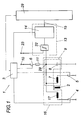
- a target 2 has a controller 3, which is connected to the switches 4, 5 and 6.
- a coil 7 cooperates inductively, so that it comes with a relative movement of the target 2 relative to the coil 7, depending on the operating principle and "apparent" change of the inductance of the coil 7, which can be detected.
- the coil 7 forms with the capacity 8 a resonant circuit 9, for which the coil 7 is connected to the capacitor 8 and the switch 5 is closed.
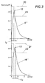
- the oscillating circuit 9 has been to be excited to produce an underdamped vibration 9 '(which is also referred to as damped vibration) or an overdamped vibration 9 "(which is usually referred to as a discharge curve), for which purpose a power supply 10 is provided, which Control can be switched on the switch 6.
- a power supply 10 which Control can be switched on the switch 6.
- the switch 5 and the switch 4 is open, so that the capacitor 8 can be charged via the resistor 11 to a starting voltage 12.
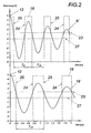
- the switch 6 is opened, and the switch 5 for the production of Fig. 2 respectively.
- Fig. 3 The respective mode of vibration can be adjusted by a suitable choice of the electrical parameters of the components in question and is readily possible for a person skilled in the art.
- This oscillation 9 'or 9 is evaluated by an evaluation circuit 13.
- the evaluation circuit 13 on a timing element 14 that is connected to the resonant circuit 9 for generating, dependent on the excitation of the resonant circuit 9 timing data t 9 ' and t 9 " tapped at the output of the timing element via a data bus 15 can be what the Figures 2 and 3 can be seen.
- the time measurement data t 9 ' or t 9 " can now be deduced the position of the target 2, because this is recognizable in a change to the previous oscillation or to the relevant previous time measurement data to be able to perform an extremely accurate position measurement, points the device 1 has a reference coil 17 which can be connected to the capacitance 8 to form a second oscillating circuit 16.
- either the coil 7 or the reference coil 17 now forms a resonant circuit 9 excited by the power supply 10 16 and 16 with the capacitance 8, wherein for each resonant circuit 9 or 16, the controller 3 charges the capacitor 8 to a starting voltage 12 via the switch 6, as already explained above second oscillating circuit 16 are therefore available additional time measurement data t 16 ' or t 16 " on the data bus 15.
- This Data can then be sent to a computing unit 29 be fed so as to compensate for interference effects by the capacity 8 in the position measurement can. For example, then the effect of aging of the capacitance 8 in the position measurement is no longer a, whereby a frequent maintenance to balance the device 1 can be omitted. It is conceivable to take into account for measuring the position and time measurement data of a vibration of a resonant circuit of coil 7 parallel to the reference coil 17 with the capacity, which has not been shown in detail.
- the reference coil 17, which is essentially the same in particular in the inductive properties of the coil 7, also interacts inductively with the target 2 for position measurement.
- the reference coil can therefore serve not only to balance the device but also to provide position-dependent time measurement data t 16 ' or t 16 "of the arithmetic unit 29.
- this is advantageous when the reference coil 17 is arranged relative to the target 2 and the coil 7 such that the reference coil 17 is subjected to a change in position of the target 2 with a substantially opposite to the coil 7 inductive change, which in Fig. 1 is shown in more detail. It can be seen that, when the target 2 is displaced in the direction of the coil 7, the same change in the distance between the target 2 and the reference coil 17 occurs. This change in position is not only in the time measurement data t 9 ' and t 9 " and t 16' and t 16" recognizable, but it can also be interfering with the position measurement and interference, acting on both coils 7 and 17, eliminated with a difference become what creates a particularly self-sufficient device 1.
- the timing element 14 is designed such that it can make a time measurement on the basis of switching signals 18 and 19 or 20 and 21.
- the evaluation circuit 13 comprises a comparator 22 connected to the resonant circuit 9, 16 and the time measuring element 14, in particular a comparator.
- the comparison stage 22 now generates a dependent of the excited resonant circuit 9, 16 and a comparison voltage 23 switching signal 18 and 19 and 20 and 21, based on the timing element 14 can easily make a time measurement.
- the pulse-like switching signals 18 and 19 or 20 and 21 have rising signal edges 24 and falling signal edges 25, based on which the timing element 14 time measurement data t 9 ' and t 9 " and t 16' and t 19" generates.
- timing data t 9 ' or t 9 " or t 16' or t 16" and / or t 26 can be used between the falling and / or rising signal edges 24 and / or 25.
- the coils 7 and 17 interact inductively with the target 2 according to the eddy current principle in order to be able to use a changed signal attenuation in addition to a frequency change for the time measurement. Furthermore, the resonant circuits 9 and 16 are electrically designed such that in these excitation an underdamped oscillation 9 'or 16' is formed. In order to increase the resolution of the time measurement or position measurement, the comparison voltage 23 has a voltage level lying between the heights of the starting voltage 12 and the quiescent voltage 27 of the oscillating circuits 9 and 16, which results in the Figures 2 and 3 can be removed.
- Fig. 4 can be a schematic representation of a use of Fig. 1 shown device to be detected in an electric machine with a magnetic bearing, wherein for the sake of clarity, only the rotor of the electric machine can be seen.
- the rotor serves as a target for the coils 7, 17, 7 'and 17'.
- the coils 7, 17 and 7 ', 17' are each connected via nodes 28 and 28 'with other components, which have been omitted for clarity.
- the other components will be apparent to one skilled in the art with a linkage of the node 28 of Fig. 1 with the nodes 28 and 28 '.
- a parallel construction connected at a node 28 and 28 ' is provided in order to provide on the basis of the parallelization for a faster position measurement can.
- the data of the position measurement to the target 2 can then be supplied to the magnetic bearing control so as to adjust the position of the rotor to the stator in that the magnetic bearing control controls the magnetic bearing.
- a coil 7 or 7 'and a reference coil 17 or 17' are arranged diametrically opposite each other at a distance from the rotor for each radial movement axis of the rotor.
- the after Fig. 1 shown device 1 for measuring the relative movement can also be used for an angle measurement, which is the Fig. 5 can be taken closer.
- the coils 7 and 17 are aligned with respect to a disc-shaped target 2 and interact with this inductively.
- the target 2 has various cake corner-shaped fields 30 and 31, which act inductively on the coils 7 and 17 in different ways, so that upon rotation of the target 2, its relative movement can be detected and recorded by time measurement data from the device.
- the number of fields 30, 31 can be adjusted.
Landscapes
- Physics & Mathematics (AREA)
- General Physics & Mathematics (AREA)
- Transmission And Conversion Of Sensor Element Output (AREA)
- Measurement Of Length, Angles, Or The Like Using Electric Or Magnetic Means (AREA)
Claims (10)
- Dispositif (1) de mesure d'un mouvement relatif d'une cible (2), comportant une commande (3) ; au moins une bobine (7) et au moins une bobine de référence (17), les deux bobines (7 et 17) interagissant de façon inductive avec la cible (2) pour la mesure d'un mouvement relatif; un condensateur (8) connecté à la bobine (7) et/ou à la bobine de référence (17), au moins des parties du condensateur (8) et des bobines (7, 17)) formant au moins deux circuits oscillants électriques (9, 16) ; au moins une alimentation électrique (10) connectée à la commande (3), destinée à exciter les circuits oscillants (9, 16) ; et au moins un circuit d'évaluation (13) comprenant un organe de mesure temporelle (14), notamment un organe TDC (convertisseur temps/numérique), connecté aux circuits oscillants (9, 16) pour produire des données de mesure temporelle (t9' ou. t9" et t16' ou t16") dépendant de l'excitation respective des circuits oscillants (9, 16), permettant de déduire le mouvement relatif de la cible (2), caractérisé en ce que la bobine de référence (17) est disposée de telle manière par rapport à la cible (2) et à la bobine (7) que la bobine de référence (17) est soumise à une variation inductive essentiellement opposée à la bobine (7) en cas de mouvement relatif de la cible (2) afin de pouvoir déduire le mouvement relatif de la cible (2) sur la base d'une soustraction des données de mesure temporelle (t9', t9" et t16', t16").
- Dispositif selon revendication 1, caractérisé en ce que la bobine de référence (17) est définie dans ses propriétés inductives essentiellement identiques à la bobine (7).
- Dispositif selon revendication 1 ou 2, caractérisé en ce qu'en fonction de la commande (3), soit la bobine (7) soit la bobine de référence (17) définit un circuit oscillant (9, 16) excité par l'alimentation électrique, avec le condensateur (8).
- Dispositif selon revendication 1, 2 ou 3, caractérisé en ce que le circuit d'évaluation (13) comprend une étape de comparaison (22) reliée aux circuits oscillants (9, 16) et à l'organe de mesure temporelle (14), ladite étape produisant, pour la mesure temporelle, un signal de commutation (18, 19 et 20, 31) dépendant de chaque circuit oscillant (9, 16) excité et d'une tension de comparaison (23), pour l'organe de mesure temporelle (14).
- Dispositif selon revendication 4, caractérisé en ce qu'au moins la bobine (7) interagit de manière inductive avec la cible (2) d'après le principe des courants de Foucault, et en ce que par les circuits oscillants (9, 16) au moins le circuit oscillant (9) est disposé électriquement avec la bobine (7) de manière à ce que dans ce circuit, en cas d'excitation une oscillation (9') à faible amortissement apparaît, où la tension de comparaison (23) présente une hauteur de tension située entre les hauteurs de tension d'excitation et de repos (12, 27) du circuit oscillant (7).
- Dispositif selon revendication 4 ou 5, caractérisé en ce que l'étape de comparaison (22) pour la transmission d'un signal de commutation (18 ou 19 et 20 ou 21) présentant au moins deux flancs de signal (24, 25), est reliée à l'organe de mesure temporelle (14) où l'organe de mesure temporelle (14) produit des données de mesure temporelle sur la base de mesures temporelles entre les flancs (24, 25) différents d'un point de vue temporel.
- Application du dispositif de mesure d'un mouvement relatif d'une cible (2), selon l'une des revendications 1 à 6, avec une machine électrique, plus particulièrement un moteur sans palier, dont la machine électrique présente un rotor, un stator et un palier magnétique logeant le rotor au stator, avec une commande à palier magnétique, où le rotor sert, du moins partiellement, à mesurer la position en tant que cible (2) pour le dispositif (1), et la commande à palier magnétique considérant cette mesure du dispositif (1) commande en contrôlant le palier magnétique.
- Application selon la revendication 7, caractérisé en ce que, pour chaque axe de mouvement radial du rotor, une bobine (7, 7') et une bobine de référence (17, 17") sont agencées de manière diamétralement opposée à une certaine distance du rotor.
- Procédé de mesure d'un mouvement relatif d'une cible (2) où à l'aide d'une oscillation (9', 9") électrique de faible ou de fort amortissement d'un circuit oscillant excité (9) qui se forme au moins entre un condensateur (8) et une bobine (7) interagissant de manière inductive avec la cible (2), regroupe des données de mesure temporelle (t9', t9"), permettant de déduire le mouvement relatif de la cible (2), où les données de mesure temporelle (t16', t16") d'une autre oscillation (16', 16") électrique de faible ou de fort amortissement d'un deuxième circuit oscillant (16) excité, seront de surcroît prises en compte pour la mesure, ledit circuit se formant au moins entre le bobine de référence (17) et le condensateur (8) de l'un des circuits oscillants (9), caractérisé en ce que lors de la mesure, une différence est prise en compte en fonction des données temporelles saisies (t9', t16' ou t9", t16") du premier et du deuxième circuit oscillant (9, 16), où la bobine de référence (17) interagit de manière inductive avec la cible (2) au moins lors d'une mesure temporelle du deuxième circuit oscillant (16).
- Procédé selon revendication 9, caractérisé en ce que pour produire l'oscillation (9', 16' ou 9", 16") électrique de faible ou de fort amortissement soit la bobine (7) soit la bobine de référence (17) définit un circuit oscillant (9, 16) avec le condensateur (8).
Applications Claiming Priority (2)
| Application Number | Priority Date | Filing Date | Title |
|---|---|---|---|
| ATA665/2009A AT508189B1 (de) | 2009-04-30 | 2009-04-30 | Vorrichtung und verfahren zur messung einer relativbewegung eines targets |
| PCT/AT2010/000135 WO2010124310A2 (fr) | 2009-04-30 | 2010-04-29 | Dispositif et procédé de mesure d'un mouvement relatif d'une cible |
Publications (2)
| Publication Number | Publication Date |
|---|---|
| EP2425207A2 EP2425207A2 (fr) | 2012-03-07 |
| EP2425207B1 true EP2425207B1 (fr) | 2015-09-30 |
Family
ID=42791136
Family Applications (1)
| Application Number | Title | Priority Date | Filing Date |
|---|---|---|---|
| EP10720240.0A Active EP2425207B1 (fr) | 2009-04-30 | 2010-04-29 | Dispositif et procédé de mesure d'un mouvement relatif d'une cible |
Country Status (3)
| Country | Link |
|---|---|
| EP (1) | EP2425207B1 (fr) |
| AT (1) | AT508189B1 (fr) |
| WO (1) | WO2010124310A2 (fr) |
Families Citing this family (2)
| Publication number | Priority date | Publication date | Assignee | Title |
|---|---|---|---|---|
| AT511602B1 (de) * | 2011-12-30 | 2013-01-15 | Johannes Kepler Uni | Vorrichtung und verfahren zur messung einer relativbewegung eines targets |
| DE102013208600A1 (de) * | 2013-05-10 | 2014-11-13 | Robert Bosch Gmbh | Erregervorrichtung für einen Winkellagegeber |
Family Cites Families (5)
| Publication number | Priority date | Publication date | Assignee | Title |
|---|---|---|---|---|
| US4644570A (en) * | 1985-09-20 | 1987-02-17 | Bitronics, Inc. | Sensor amplification and enhancement apparatus using digital techniques |
| DE4237879A1 (de) * | 1992-11-10 | 1994-05-11 | Bosch Gmbh Robert | Auswerteschaltung für einen Induktivsensor |
| DE10130572B4 (de) * | 2001-06-27 | 2010-01-07 | Ifm Electronic Gmbh | Induktiver Wegsensor zur Bestimmung der Position eines Beeinflussungselements und Verfahren zur Bestimmung der Position eines Beeinflussungselements mit einem induktiven Wegsensor |
| DE10322447A1 (de) * | 2003-05-19 | 2004-12-09 | Bayerische Motoren Werke Ag | Positionsmessvorrichtung und Verfahren zur Positionsermittlung |
| DE102004032258B4 (de) * | 2004-06-11 | 2018-05-30 | Balluff Gmbh | Induktiver Näherungssensor |
-
2009
- 2009-04-30 AT ATA665/2009A patent/AT508189B1/de not_active IP Right Cessation
-
2010
- 2010-04-29 EP EP10720240.0A patent/EP2425207B1/fr active Active
- 2010-04-29 WO PCT/AT2010/000135 patent/WO2010124310A2/fr not_active Ceased
Also Published As
| Publication number | Publication date |
|---|---|
| AT508189A1 (de) | 2010-11-15 |
| EP2425207A2 (fr) | 2012-03-07 |
| WO2010124310A2 (fr) | 2010-11-04 |
| AT508189B1 (de) | 2012-04-15 |
| WO2010124310A3 (fr) | 2010-12-23 |
Similar Documents
| Publication | Publication Date | Title |
|---|---|---|
| EP1419365B1 (fr) | Dispositif et procede de lecture d'un condensateur differentiel comportant un premier et un deuxieme condensateur partiel | |
| DE69631691T2 (de) | Spielmesssystem | |
| DE102007002705B4 (de) | Vorrichtung und Verfahren zum Erfassen einer Richtungsumkehr einer Relativbewegung | |
| DE102007007551A1 (de) | Induktiver Näherungssensor | |
| DE202018006650U1 (de) | Elektronisches Gerät mit induktivem Sensor | |
| EP3030862B1 (fr) | Circuit et procédé de commande d'un capteur de déplacement | |
| DE2940083A1 (de) | Frequenzgenerator | |
| EP2425207B1 (fr) | Dispositif et procédé de mesure d'un mouvement relatif d'une cible | |
| DE102016209366A1 (de) | Verfahren und Vorrichtung zur Kalibrierung eines Stellgebersystems | |
| DE102014113545A1 (de) | Vorrichtung und Verfahren zur Überwachung einer Prozessgröße eines Mediums | |
| DE69112398T2 (de) | Verfahren und vorrichtung zum prüfen von münzen. | |
| DE2649621C2 (de) | Vorrichtung zur Messung der Geschwindigkeit eines Fahrzeuges | |
| DE69114479T2 (de) | Lagedetektor. | |
| DE102017128472A1 (de) | Induktiver Näherungsschalter und Verfahren zum Betreiben eines induktiven Näherungsschalters | |
| DE102018105234B4 (de) | Verfahren zum Betreiben eines kapazitiven Druckmessgeräts | |
| EP3117182A1 (fr) | Procédé d'optimisation du temps de fermeture dans un gyroscope de coriolis et gyroscope de coriolis adapté à cette fin | |
| DE102017128471A1 (de) | Induktiver Näherungsschalter und Verfahren zum Betreiben eines induktiven Näherungsschalters | |
| EP2291615B1 (fr) | Capteur inductif | |
| DE3115195C2 (fr) | ||
| DE10344983B3 (de) | Verfahren zum Laden eines aktiv abgeschirmten supraleitenden NMR-Magneten | |
| DE102022133045B4 (de) | Kompensationsverfahren zur Resonanzdetektion | |
| EP4513199B1 (fr) | Commutateur de proximité pour la mesure de la vitesse d'un objet à mesurer | |
| EP2798312B1 (fr) | Dispositif et procédé de mesure d'un mouvement relatif d'une cible | |
| DE102008064544A1 (de) | Positions-/Wegmesssystem und Verfahren zur Bestimmung der Position eines Gebers | |
| EP3557188A1 (fr) | Bielle magnétisée destinée à la mesure de cours |
Legal Events
| Date | Code | Title | Description |
|---|---|---|---|
| PUAI | Public reference made under article 153(3) epc to a published international application that has entered the european phase |
Free format text: ORIGINAL CODE: 0009012 |
|
| 17P | Request for examination filed |
Effective date: 20111130 |
|
| AK | Designated contracting states |
Kind code of ref document: A2 Designated state(s): AT BE BG CH CY CZ DE DK EE ES FI FR GB GR HR HU IE IS IT LI LT LU LV MC MK MT NL NO PL PT RO SE SI SK SM TR |
|
| DAX | Request for extension of the european patent (deleted) | ||
| GRAP | Despatch of communication of intention to grant a patent |
Free format text: ORIGINAL CODE: EPIDOSNIGR1 |
|
| INTG | Intention to grant announced |
Effective date: 20150414 |
|
| GRAS | Grant fee paid |
Free format text: ORIGINAL CODE: EPIDOSNIGR3 |
|
| GRAA | (expected) grant |
Free format text: ORIGINAL CODE: 0009210 |
|
| AK | Designated contracting states |
Kind code of ref document: B1 Designated state(s): AT BE BG CH CY CZ DE DK EE ES FI FR GB GR HR HU IE IS IT LI LT LU LV MC MK MT NL NO PL PT RO SE SI SK SM TR |
|
| RAP1 | Party data changed (applicant data changed or rights of an application transferred) |
Owner name: AUSTRIAN CENTER OF COMPETENCE IN MECHATRONICS GMBH |
|
| REG | Reference to a national code |
Ref country code: CH Ref legal event code: EP Ref country code: GB Ref legal event code: FG4D Free format text: NOT ENGLISH |
|
| REG | Reference to a national code |
Ref country code: AT Ref legal event code: REF Ref document number: 752683 Country of ref document: AT Kind code of ref document: T Effective date: 20151015 |
|
| REG | Reference to a national code |
Ref country code: IE Ref legal event code: FG4D Free format text: LANGUAGE OF EP DOCUMENT: GERMAN |
|
| REG | Reference to a national code |
Ref country code: DE Ref legal event code: R096 Ref document number: 502010010384 Country of ref document: DE |
|
| REG | Reference to a national code |
Ref country code: DE Ref legal event code: R082 Ref document number: 502010010384 Country of ref document: DE Representative=s name: WOLF & WOLF PATENT- UND RECHTSANWAELTE, DE Ref country code: DE Ref legal event code: R081 Ref document number: 502010010384 Country of ref document: DE Owner name: LINZ CENTER OF MECHATRONICS GMBH, AT Free format text: FORMER OWNER: AUSTRIAN CENTER OF COMPETENCE IN MECHATRONICS GMBH, LINZ, AT Ref country code: DE Ref legal event code: R082 Ref document number: 502010010384 Country of ref document: DE Representative=s name: WOLF & WOLF PATENT- UND RECHTSANWALTSGESELLSCH, DE Ref country code: DE Ref legal event code: R082 Ref document number: 502010010384 Country of ref document: DE Representative=s name: WOLF & WOLF PATENT- UND RECHTSANWAELTE GBR, DE |
|
| REG | Reference to a national code |
Ref country code: CH Ref legal event code: PFUS Owner name: LINZ CENTER OF MECHATRONICS GMBH, AT Free format text: FORMER OWNER: AUSTRIAN CENTER OF COMPETENCE IN MECHATRONICS GMBH, AT Ref country code: CH Ref legal event code: NV Representative=s name: ISLER AND PEDRAZZINI AG, CH |
|
| PG25 | Lapsed in a contracting state [announced via postgrant information from national office to epo] |
Ref country code: NO Free format text: LAPSE BECAUSE OF FAILURE TO SUBMIT A TRANSLATION OF THE DESCRIPTION OR TO PAY THE FEE WITHIN THE PRESCRIBED TIME-LIMIT Effective date: 20151230 Ref country code: LV Free format text: LAPSE BECAUSE OF FAILURE TO SUBMIT A TRANSLATION OF THE DESCRIPTION OR TO PAY THE FEE WITHIN THE PRESCRIBED TIME-LIMIT Effective date: 20150930 Ref country code: LT Free format text: LAPSE BECAUSE OF FAILURE TO SUBMIT A TRANSLATION OF THE DESCRIPTION OR TO PAY THE FEE WITHIN THE PRESCRIBED TIME-LIMIT Effective date: 20150930 Ref country code: FI Free format text: LAPSE BECAUSE OF FAILURE TO SUBMIT A TRANSLATION OF THE DESCRIPTION OR TO PAY THE FEE WITHIN THE PRESCRIBED TIME-LIMIT Effective date: 20150930 Ref country code: GR Free format text: LAPSE BECAUSE OF FAILURE TO SUBMIT A TRANSLATION OF THE DESCRIPTION OR TO PAY THE FEE WITHIN THE PRESCRIBED TIME-LIMIT Effective date: 20151231 |
|
| REG | Reference to a national code |
Ref country code: NL Ref legal event code: MP Effective date: 20150930 |
|
| REG | Reference to a national code |
Ref country code: LT Ref legal event code: MG4D |
|
| PG25 | Lapsed in a contracting state [announced via postgrant information from national office to epo] |
Ref country code: HR Free format text: LAPSE BECAUSE OF FAILURE TO SUBMIT A TRANSLATION OF THE DESCRIPTION OR TO PAY THE FEE WITHIN THE PRESCRIBED TIME-LIMIT Effective date: 20150930 Ref country code: SE Free format text: LAPSE BECAUSE OF FAILURE TO SUBMIT A TRANSLATION OF THE DESCRIPTION OR TO PAY THE FEE WITHIN THE PRESCRIBED TIME-LIMIT Effective date: 20150930 |
|
| RAP2 | Party data changed (patent owner data changed or rights of a patent transferred) |
Owner name: LINZ CENTER OF MECHATRONICS GMBH |
|
| REG | Reference to a national code |
Ref country code: GB Ref legal event code: 732E Free format text: REGISTERED BETWEEN 20160317 AND 20160323 |
|
| REG | Reference to a national code |
Ref country code: FR Ref legal event code: PLFP Year of fee payment: 7 |
|
| PG25 | Lapsed in a contracting state [announced via postgrant information from national office to epo] |
Ref country code: CZ Free format text: LAPSE BECAUSE OF FAILURE TO SUBMIT A TRANSLATION OF THE DESCRIPTION OR TO PAY THE FEE WITHIN THE PRESCRIBED TIME-LIMIT Effective date: 20150930 Ref country code: IS Free format text: LAPSE BECAUSE OF FAILURE TO SUBMIT A TRANSLATION OF THE DESCRIPTION OR TO PAY THE FEE WITHIN THE PRESCRIBED TIME-LIMIT Effective date: 20160130 Ref country code: SK Free format text: LAPSE BECAUSE OF FAILURE TO SUBMIT A TRANSLATION OF THE DESCRIPTION OR TO PAY THE FEE WITHIN THE PRESCRIBED TIME-LIMIT Effective date: 20150930 Ref country code: NL Free format text: LAPSE BECAUSE OF FAILURE TO SUBMIT A TRANSLATION OF THE DESCRIPTION OR TO PAY THE FEE WITHIN THE PRESCRIBED TIME-LIMIT Effective date: 20150930 Ref country code: ES Free format text: LAPSE BECAUSE OF FAILURE TO SUBMIT A TRANSLATION OF THE DESCRIPTION OR TO PAY THE FEE WITHIN THE PRESCRIBED TIME-LIMIT Effective date: 20150930 Ref country code: EE Free format text: LAPSE BECAUSE OF FAILURE TO SUBMIT A TRANSLATION OF THE DESCRIPTION OR TO PAY THE FEE WITHIN THE PRESCRIBED TIME-LIMIT Effective date: 20150930 |
|
| PG25 | Lapsed in a contracting state [announced via postgrant information from national office to epo] |
Ref country code: PL Free format text: LAPSE BECAUSE OF FAILURE TO SUBMIT A TRANSLATION OF THE DESCRIPTION OR TO PAY THE FEE WITHIN THE PRESCRIBED TIME-LIMIT Effective date: 20150930 Ref country code: RO Free format text: LAPSE BECAUSE OF FAILURE TO SUBMIT A TRANSLATION OF THE DESCRIPTION OR TO PAY THE FEE WITHIN THE PRESCRIBED TIME-LIMIT Effective date: 20150930 Ref country code: PT Free format text: LAPSE BECAUSE OF FAILURE TO SUBMIT A TRANSLATION OF THE DESCRIPTION OR TO PAY THE FEE WITHIN THE PRESCRIBED TIME-LIMIT Effective date: 20160201 |
|
| REG | Reference to a national code |
Ref country code: DE Ref legal event code: R097 Ref document number: 502010010384 Country of ref document: DE |
|
| PLBE | No opposition filed within time limit |
Free format text: ORIGINAL CODE: 0009261 |
|
| STAA | Information on the status of an ep patent application or granted ep patent |
Free format text: STATUS: NO OPPOSITION FILED WITHIN TIME LIMIT |
|
| PG25 | Lapsed in a contracting state [announced via postgrant information from national office to epo] |
Ref country code: BE Free format text: LAPSE BECAUSE OF NON-PAYMENT OF DUE FEES Effective date: 20160430 Ref country code: DK Free format text: LAPSE BECAUSE OF FAILURE TO SUBMIT A TRANSLATION OF THE DESCRIPTION OR TO PAY THE FEE WITHIN THE PRESCRIBED TIME-LIMIT Effective date: 20150930 |
|
| 26N | No opposition filed |
Effective date: 20160701 |
|
| PG25 | Lapsed in a contracting state [announced via postgrant information from national office to epo] |
Ref country code: SI Free format text: LAPSE BECAUSE OF FAILURE TO SUBMIT A TRANSLATION OF THE DESCRIPTION OR TO PAY THE FEE WITHIN THE PRESCRIBED TIME-LIMIT Effective date: 20150930 |
|
| PG25 | Lapsed in a contracting state [announced via postgrant information from national office to epo] |
Ref country code: LU Free format text: LAPSE BECAUSE OF FAILURE TO SUBMIT A TRANSLATION OF THE DESCRIPTION OR TO PAY THE FEE WITHIN THE PRESCRIBED TIME-LIMIT Effective date: 20160429 |
|
| REG | Reference to a national code |
Ref country code: IE Ref legal event code: MM4A |
|
| REG | Reference to a national code |
Ref country code: FR Ref legal event code: PLFP Year of fee payment: 8 |
|
| PG25 | Lapsed in a contracting state [announced via postgrant information from national office to epo] |
Ref country code: IE Free format text: LAPSE BECAUSE OF NON-PAYMENT OF DUE FEES Effective date: 20160429 |
|
| REG | Reference to a national code |
Ref country code: AT Ref legal event code: PC Ref document number: 752683 Country of ref document: AT Kind code of ref document: T Owner name: LINZ CENTER OF MECHATRONICS GMBH, AT Effective date: 20180126 |
|
| REG | Reference to a national code |
Ref country code: FR Ref legal event code: PLFP Year of fee payment: 9 |
|
| PG25 | Lapsed in a contracting state [announced via postgrant information from national office to epo] |
Ref country code: CY Free format text: LAPSE BECAUSE OF FAILURE TO SUBMIT A TRANSLATION OF THE DESCRIPTION OR TO PAY THE FEE WITHIN THE PRESCRIBED TIME-LIMIT Effective date: 20150930 Ref country code: HU Free format text: LAPSE BECAUSE OF FAILURE TO SUBMIT A TRANSLATION OF THE DESCRIPTION OR TO PAY THE FEE WITHIN THE PRESCRIBED TIME-LIMIT; INVALID AB INITIO Effective date: 20100429 Ref country code: SM Free format text: LAPSE BECAUSE OF FAILURE TO SUBMIT A TRANSLATION OF THE DESCRIPTION OR TO PAY THE FEE WITHIN THE PRESCRIBED TIME-LIMIT Effective date: 20150930 |
|
| PG25 | Lapsed in a contracting state [announced via postgrant information from national office to epo] |
Ref country code: MK Free format text: LAPSE BECAUSE OF FAILURE TO SUBMIT A TRANSLATION OF THE DESCRIPTION OR TO PAY THE FEE WITHIN THE PRESCRIBED TIME-LIMIT Effective date: 20150930 Ref country code: TR Free format text: LAPSE BECAUSE OF FAILURE TO SUBMIT A TRANSLATION OF THE DESCRIPTION OR TO PAY THE FEE WITHIN THE PRESCRIBED TIME-LIMIT Effective date: 20150930 Ref country code: MC Free format text: LAPSE BECAUSE OF FAILURE TO SUBMIT A TRANSLATION OF THE DESCRIPTION OR TO PAY THE FEE WITHIN THE PRESCRIBED TIME-LIMIT Effective date: 20150930 Ref country code: MT Free format text: LAPSE BECAUSE OF FAILURE TO SUBMIT A TRANSLATION OF THE DESCRIPTION OR TO PAY THE FEE WITHIN THE PRESCRIBED TIME-LIMIT Effective date: 20150930 |
|
| PG25 | Lapsed in a contracting state [announced via postgrant information from national office to epo] |
Ref country code: BG Free format text: LAPSE BECAUSE OF FAILURE TO SUBMIT A TRANSLATION OF THE DESCRIPTION OR TO PAY THE FEE WITHIN THE PRESCRIBED TIME-LIMIT Effective date: 20150930 |
|
| PGFP | Annual fee paid to national office [announced via postgrant information from national office to epo] |
Ref country code: IT Payment date: 20210430 Year of fee payment: 12 |
|
| PGFP | Annual fee paid to national office [announced via postgrant information from national office to epo] |
Ref country code: AT Payment date: 20210420 Year of fee payment: 12 |
|
| REG | Reference to a national code |
Ref country code: AT Ref legal event code: MM01 Ref document number: 752683 Country of ref document: AT Kind code of ref document: T Effective date: 20220429 |
|
| PG25 | Lapsed in a contracting state [announced via postgrant information from national office to epo] |
Ref country code: AT Free format text: LAPSE BECAUSE OF NON-PAYMENT OF DUE FEES Effective date: 20220429 |
|
| PG25 | Lapsed in a contracting state [announced via postgrant information from national office to epo] |
Ref country code: IT Free format text: LAPSE BECAUSE OF NON-PAYMENT OF DUE FEES Effective date: 20220429 |
|
| P01 | Opt-out of the competence of the unified patent court (upc) registered |
Effective date: 20230526 |
|
| PGFP | Annual fee paid to national office [announced via postgrant information from national office to epo] |
Ref country code: GB Payment date: 20240423 Year of fee payment: 15 |
|
| PGFP | Annual fee paid to national office [announced via postgrant information from national office to epo] |
Ref country code: DE Payment date: 20240418 Year of fee payment: 15 |
|
| PGFP | Annual fee paid to national office [announced via postgrant information from national office to epo] |
Ref country code: CH Payment date: 20240501 Year of fee payment: 15 |
|
| PGFP | Annual fee paid to national office [announced via postgrant information from national office to epo] |
Ref country code: FR Payment date: 20240419 Year of fee payment: 15 |
|
| REG | Reference to a national code |
Ref country code: DE Ref legal event code: R119 Ref document number: 502010010384 Country of ref document: DE |
|
| REG | Reference to a national code |
Ref country code: CH Ref legal event code: H13 Free format text: ST27 STATUS EVENT CODE: U-0-0-H10-H13 (AS PROVIDED BY THE NATIONAL OFFICE) Effective date: 20251125 |
|
| GBPC | Gb: european patent ceased through non-payment of renewal fee |
Effective date: 20250429 |
|
| PG25 | Lapsed in a contracting state [announced via postgrant information from national office to epo] |
Ref country code: DE Free format text: LAPSE BECAUSE OF NON-PAYMENT OF DUE FEES Effective date: 20251104 |
|
| PG25 | Lapsed in a contracting state [announced via postgrant information from national office to epo] |
Ref country code: GB Free format text: LAPSE BECAUSE OF NON-PAYMENT OF DUE FEES Effective date: 20250429 |
|
| PG25 | Lapsed in a contracting state [announced via postgrant information from national office to epo] |
Ref country code: FR Free format text: LAPSE BECAUSE OF NON-PAYMENT OF DUE FEES Effective date: 20250430 |
|
| PG25 | Lapsed in a contracting state [announced via postgrant information from national office to epo] |
Ref country code: CH Free format text: LAPSE BECAUSE OF NON-PAYMENT OF DUE FEES Effective date: 20250430 |