EP2425207B1 - Apparatus and method for measuring a relative movement of a target - Google Patents
Apparatus and method for measuring a relative movement of a target Download PDFInfo
- Publication number
- EP2425207B1 EP2425207B1 EP10720240.0A EP10720240A EP2425207B1 EP 2425207 B1 EP2425207 B1 EP 2425207B1 EP 10720240 A EP10720240 A EP 10720240A EP 2425207 B1 EP2425207 B1 EP 2425207B1
- Authority
- EP
- European Patent Office
- Prior art keywords
- coil
- target
- relative movement
- time
- oscillating circuit
- Prior art date
- Legal status (The legal status is an assumption and is not a legal conclusion. Google has not performed a legal analysis and makes no representation as to the accuracy of the status listed.)
- Active
Links
Images


Classifications
-
- G—PHYSICS
- G01—MEASURING; TESTING
- G01D—MEASURING NOT SPECIALLY ADAPTED FOR A SPECIFIC VARIABLE; ARRANGEMENTS FOR MEASURING TWO OR MORE VARIABLES NOT COVERED IN A SINGLE OTHER SUBCLASS; TARIFF METERING APPARATUS; MEASURING OR TESTING NOT OTHERWISE PROVIDED FOR
- G01D5/00—Mechanical means for transferring the output of a sensing member; Means for converting the output of a sensing member to another variable where the form or nature of the sensing member does not constrain the means for converting; Transducers not specially adapted for a specific variable
- G01D5/12—Mechanical means for transferring the output of a sensing member; Means for converting the output of a sensing member to another variable where the form or nature of the sensing member does not constrain the means for converting; Transducers not specially adapted for a specific variable using electric or magnetic means
- G01D5/14—Mechanical means for transferring the output of a sensing member; Means for converting the output of a sensing member to another variable where the form or nature of the sensing member does not constrain the means for converting; Transducers not specially adapted for a specific variable using electric or magnetic means influencing the magnitude of a current or voltage
- G01D5/20—Mechanical means for transferring the output of a sensing member; Means for converting the output of a sensing member to another variable where the form or nature of the sensing member does not constrain the means for converting; Transducers not specially adapted for a specific variable using electric or magnetic means influencing the magnitude of a current or voltage by varying inductance, e.g. by a movable armature
- G01D5/22—Mechanical means for transferring the output of a sensing member; Means for converting the output of a sensing member to another variable where the form or nature of the sensing member does not constrain the means for converting; Transducers not specially adapted for a specific variable using electric or magnetic means influencing the magnitude of a current or voltage by varying inductance, e.g. by a movable armature differentially influencing two coils
- G01D5/2208—Mechanical means for transferring the output of a sensing member; Means for converting the output of a sensing member to another variable where the form or nature of the sensing member does not constrain the means for converting; Transducers not specially adapted for a specific variable using electric or magnetic means influencing the magnitude of a current or voltage by varying inductance, e.g. by a movable armature differentially influencing two coils by influencing the self-induction of the coils
- G01D5/2216—Mechanical means for transferring the output of a sensing member; Means for converting the output of a sensing member to another variable where the form or nature of the sensing member does not constrain the means for converting; Transducers not specially adapted for a specific variable using electric or magnetic means influencing the magnitude of a current or voltage by varying inductance, e.g. by a movable armature differentially influencing two coils by influencing the self-induction of the coils by a movable ferromagnetic element, e.g. a core
-
- G—PHYSICS
- G01—MEASURING; TESTING
- G01D—MEASURING NOT SPECIALLY ADAPTED FOR A SPECIFIC VARIABLE; ARRANGEMENTS FOR MEASURING TWO OR MORE VARIABLES NOT COVERED IN A SINGLE OTHER SUBCLASS; TARIFF METERING APPARATUS; MEASURING OR TESTING NOT OTHERWISE PROVIDED FOR
- G01D5/00—Mechanical means for transferring the output of a sensing member; Means for converting the output of a sensing member to another variable where the form or nature of the sensing member does not constrain the means for converting; Transducers not specially adapted for a specific variable
- G01D5/12—Mechanical means for transferring the output of a sensing member; Means for converting the output of a sensing member to another variable where the form or nature of the sensing member does not constrain the means for converting; Transducers not specially adapted for a specific variable using electric or magnetic means
- G01D5/14—Mechanical means for transferring the output of a sensing member; Means for converting the output of a sensing member to another variable where the form or nature of the sensing member does not constrain the means for converting; Transducers not specially adapted for a specific variable using electric or magnetic means influencing the magnitude of a current or voltage
- G01D5/20—Mechanical means for transferring the output of a sensing member; Means for converting the output of a sensing member to another variable where the form or nature of the sensing member does not constrain the means for converting; Transducers not specially adapted for a specific variable using electric or magnetic means influencing the magnitude of a current or voltage by varying inductance, e.g. by a movable armature
- G01D5/22—Mechanical means for transferring the output of a sensing member; Means for converting the output of a sensing member to another variable where the form or nature of the sensing member does not constrain the means for converting; Transducers not specially adapted for a specific variable using electric or magnetic means influencing the magnitude of a current or voltage by varying inductance, e.g. by a movable armature differentially influencing two coils
- G01D5/2208—Mechanical means for transferring the output of a sensing member; Means for converting the output of a sensing member to another variable where the form or nature of the sensing member does not constrain the means for converting; Transducers not specially adapted for a specific variable using electric or magnetic means influencing the magnitude of a current or voltage by varying inductance, e.g. by a movable armature differentially influencing two coils by influencing the self-induction of the coils
- G01D5/2225—Mechanical means for transferring the output of a sensing member; Means for converting the output of a sensing member to another variable where the form or nature of the sensing member does not constrain the means for converting; Transducers not specially adapted for a specific variable using electric or magnetic means influencing the magnitude of a current or voltage by varying inductance, e.g. by a movable armature differentially influencing two coils by influencing the self-induction of the coils by a movable non-ferromagnetic conductive element
Definitions
- the invention relates to a device for measuring a relative movement of a target, comprising a controller, with at least one coil and at least one reference coil, which inductively cooperate with the target for measuring a relative movement, with one connected to the coil and / or with the reference coil Capacitance, wherein at least parts of the capacitance and the coils form at least two electrical oscillating circuits, with at least one electrical power supply connected to the control for excitation of the oscillating circuits and with an evaluation circuit having a timing element, in particular a TDC element, connected to the oscillating circuits for generating, is connected by the respective excitation of the resonant circuits dependent timing data, on the relative movement of the target can be deduced.
- a controller with at least one coil and at least one reference coil, which inductively cooperate with the target for measuring a relative movement, with one connected to the coil and / or with the reference coil Capacitance, wherein at least parts of the capacitance and the coils form at least two electrical oscillating circuit
- a structurally simple device for measuring a relative movement, in particular position measurement, of a target it is from the DE10322447A1 known, with the aid of a timing member, in particular a TDC member or a "Time to Digital Converter" module to record timing data from an excited resonant circuit, which resonant circuit is formed between a capacitor and a inductively cooperating with the coil coil.
- a timing member in particular a TDC member or a "Time to Digital Converter” module to record timing data from an excited resonant circuit, which resonant circuit is formed between a capacitor and a inductively cooperating with the coil coil.
- this time measurement data which may contain, for example, information on a period of oscillation of a tapped output voltage of the resonant circuit and / or information on the decay time of the output voltage of the resonant circuit to a predetermined voltage level, now taking into account the known physical relationships and the known electrical characteristics of the components on the position be deduced the target.
- the DE10322447A1 In order to be able to take into account disturbing influences which are difficult to take into account when measuring the position, as can be the case, for example, by a temperature drift, the DE10322447A1 to provide a temperature sensor circuit with temperature sensors positioned close to the coil. Based on the temperature values measured in this way, the position of the target determined via the oscillating circuit can now be improved in accuracy.
- such circuits are relatively expensive and require in a negative way an increase in the number of analog components, which can increase both the error and the susceptibility.
- This measure is comparatively structurally complex and can not preclude mutual interference even through interaction with a common target.
- the DE10130572A1 may therefore cause interference with the individual measurement results can not avoid what a robust method of measuring a relative movement can not achieve.
- further disturbing influences which may represent, for example, aging of the analog components, of the DE10130572A1 is not taken into account, which unconsidered disturbances in general can lead to an unexpected detuning of the resonant circuit, which is particularly important factor when a time measurement is required in a comparatively short time intervals with a required high resolution or accuracy, which is generally in position measurements of time data is the case.
- the invention is therefore based on the object, starting from the above-described prior art to provide a device and a method for extremely accurate measurement of relative movement on the basis of timing data that is not only extremely self-sufficient against any interference, but also a ensure extremely accurate and repeatable measurement.
- the device should be comparatively easy to maintain and structurally simple.
- the invention achieves the stated object with regard to the device in that the reference coil is arranged relative to the target and the coil in such a way that the reference coil is acted upon by a relative movement of the target with a change that is essentially opposite to that of the coil is to be able to draw on the basis of a difference of the time measurement data on the relative movement of the target can.
- interference effects can be compensated if the reference coil is arranged relative to the target and the coil in such a way that the reference coil is subjected to a relative inductive change relative to the coil during a relative movement of the target, in order to determine the relative movement of the target based on a subtraction of the time measurement data to be able to conclude.
- the technical effect can be exploited that with a relative movement almost identical detected disturbances in a nearly identical manner in the measurement data of the two resonant circuits can be eliminated by a difference.
- Such difference formation can be performed, for example, by a computing unit, but other means for calculating a difference are conceivable.
- the device is comparatively easy to maintain in terms of their analog components, because even aging-related interference of the analog components can be neglected.
- decoupling of the coils need not be provided, because by subtracting these mutual interference can also be neglected.
- the device according to the invention is therefore characterized not only by its constructive simplicity and ease of maintenance but also by its accurate and repeatable measurement, but can also be used universally by low susceptibility, as is often required in magnetic bearings.
- a substantially opposite inductive change can be taken into account here.
- the situation may be advantageous if a reference coil which can be connected to the capacitance for forming a second resonant circuit is provided, wherein the second resonant circuit excited as a function of the control comprises at least the reference coil and the capacitance.
- the second resonant circuit excited as a function of the control comprises at least the reference coil and the capacitance.
- the influence of the disturbing effects on the measurement of a relative movement can be reduced.
- timing data of vibrations between the coil and the capacitance on the one hand and the reference coil and the capacitance on the other hand as well as oscillations between the coil, reference coil and the capacitance may be useful for this purpose.
- increased tolerances in the electrical parameters and / or even aging of the capacitance in the measurement according to the invention can be neglected, so that a device which is not only comparatively easy to adjust but also extremely resistant to disturbing influences can be created.
- the invention can therefore always ensure that an accurate and repeatable measurement, be it for position measurement or for measuring a rotation angle, is feasible.
- the device according to the invention can be comparatively easy to maintain, because an adjustment of the device or the resonant circuits in a simple manner via the reference coil is possible.
- a reference coil interacts inductively with the target for measurement, then the reference coil can likewise be used to measure the relative movement.
- the effect of the interference of the capacitance is further reduced and thus the accuracy of the measurement of the relative movement can be improved
- Constructive simplicity may result if a reference coil substantially identical in inductance to the coil is provided.
- the disturbing effects in such an embodiment are equally noticeable in both measurement results, which can ensure a simple difference.
- an adjustment of the resonant circuits with such coils can be made comparatively easy.
- Simple construction conditions for a time measurement by means of a timing element result when the evaluation circuit comprises a comparator connected to the resonant circuits and the time measuring element, which generates a timing signal dependent on the respectively excited resonant circuit and a comparison voltage for the time measuring element.
- the accuracy in the measurement of the relative movement of a target can be improved if at least the coil interacts inductively with the target according to the eddy current principle. It is then possible to use the change in the damping of electrical oscillations associated with a change in the relative position of the target, to improve the resolution of the time measurement and thus also the accuracy.
- at least the resonant circuit with the coil must be designed so electrically only of the resonant circuits, that in this under excitation vibration creates a subdued vibration, in which case the comparison voltage may have a lying between the heights of the start and rest voltage of the resonant circuit voltage level.
- the changed damping advantageously results in an increased change in the time measurement data can be used, advantageous to increase the resolution of the relative movement.
- the comparison stage for transmitting a switching signal having at least two signal edges is connected to the time measuring element, wherein the time measuring element generates time measurement data based on time measurements between temporally different edges, then the accuracy of the measurement can be further improved by also using, for example, a difference of a running time of the comparison stage can be corrected from the time measurement data.
- the device for measuring the relative movement of a target in an electric machine having a rotor, a stator and a rotor bearing on the stator magnetic bearing having a magnetic bearing control is used.
- Such an electric machine may be, for example, a bearingless motor.
- the rotor can serve as a target for the position measuring device, and on the other hand, the comparatively accurate position measurement data of the rotor can be supplied to the magnetic bearing control, when the magnetic bearing control controls the magnetic bearing in accordance with this measurement.
- a comparatively fast-reacting magnetic bearing control can be created.
- the invention solves the stated problem with regard to the method in that during the measurement a difference dependent on the acquired time data of the first and the second resonant circuit is taken into account, wherein at least during a time measurement of the second resonant circuit the reference coil cooperates inductively with the target.
- the position measurement can be improved in particular if, during the position measurement, a difference dependent on the detected time data of the first and the second resonant circuit is taken into account, wherein the reference coil cooperates inductively with the target at least during a time measurement of the second resonant circuit.
- the inductive change of the reference coil is opposite to the coil, because then an increased resolution can be created by reduced interference effects.
- the method for position measurement additionally takes into account the time measurement data of another underdamped or overdamped, electrical oscillation of a second excited resonant circuit, which forms at least between a reference coil and the capacitance of the one resonant circuit.
- the measurement can be supplied to the relative movement of a target an increased amount of time measurement data, which differ at least in the presence of the different coils or the coil and the reference coil.
- Based on the common use of the capacity can now be closed taking into account the known physical relationships and the known electrical characteristics of the components on any parasitic effects of capacity. These disturbing effects can thus be taken into account in the measurement of the relative movement, which can represent, for example, an angle or position measurement, what comparatively balanced as well as against external influences autarkic conditions for an accurate process can create.
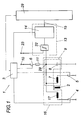
- a target 2 has a controller 3, which is connected to the switches 4, 5 and 6.
- a coil 7 cooperates inductively, so that it comes with a relative movement of the target 2 relative to the coil 7, depending on the operating principle and "apparent" change of the inductance of the coil 7, which can be detected.
- the coil 7 forms with the capacity 8 a resonant circuit 9, for which the coil 7 is connected to the capacitor 8 and the switch 5 is closed.
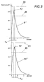
- the oscillating circuit 9 has been to be excited to produce an underdamped vibration 9 '(which is also referred to as damped vibration) or an overdamped vibration 9 "(which is usually referred to as a discharge curve), for which purpose a power supply 10 is provided, which Control can be switched on the switch 6.
- a power supply 10 which Control can be switched on the switch 6.
- the switch 5 and the switch 4 is open, so that the capacitor 8 can be charged via the resistor 11 to a starting voltage 12.
- the switch 6 is opened, and the switch 5 for the production of Fig. 2 respectively.
- Fig. 3 The respective mode of vibration can be adjusted by a suitable choice of the electrical parameters of the components in question and is readily possible for a person skilled in the art.
- This oscillation 9 'or 9 is evaluated by an evaluation circuit 13.
- the evaluation circuit 13 on a timing element 14 that is connected to the resonant circuit 9 for generating, dependent on the excitation of the resonant circuit 9 timing data t 9 ' and t 9 " tapped at the output of the timing element via a data bus 15 can be what the Figures 2 and 3 can be seen.
- the time measurement data t 9 ' or t 9 " can now be deduced the position of the target 2, because this is recognizable in a change to the previous oscillation or to the relevant previous time measurement data to be able to perform an extremely accurate position measurement, points the device 1 has a reference coil 17 which can be connected to the capacitance 8 to form a second oscillating circuit 16.
- either the coil 7 or the reference coil 17 now forms a resonant circuit 9 excited by the power supply 10 16 and 16 with the capacitance 8, wherein for each resonant circuit 9 or 16, the controller 3 charges the capacitor 8 to a starting voltage 12 via the switch 6, as already explained above second oscillating circuit 16 are therefore available additional time measurement data t 16 ' or t 16 " on the data bus 15.
- This Data can then be sent to a computing unit 29 be fed so as to compensate for interference effects by the capacity 8 in the position measurement can. For example, then the effect of aging of the capacitance 8 in the position measurement is no longer a, whereby a frequent maintenance to balance the device 1 can be omitted. It is conceivable to take into account for measuring the position and time measurement data of a vibration of a resonant circuit of coil 7 parallel to the reference coil 17 with the capacity, which has not been shown in detail.
- the reference coil 17, which is essentially the same in particular in the inductive properties of the coil 7, also interacts inductively with the target 2 for position measurement.
- the reference coil can therefore serve not only to balance the device but also to provide position-dependent time measurement data t 16 ' or t 16 "of the arithmetic unit 29.
- this is advantageous when the reference coil 17 is arranged relative to the target 2 and the coil 7 such that the reference coil 17 is subjected to a change in position of the target 2 with a substantially opposite to the coil 7 inductive change, which in Fig. 1 is shown in more detail. It can be seen that, when the target 2 is displaced in the direction of the coil 7, the same change in the distance between the target 2 and the reference coil 17 occurs. This change in position is not only in the time measurement data t 9 ' and t 9 " and t 16' and t 16" recognizable, but it can also be interfering with the position measurement and interference, acting on both coils 7 and 17, eliminated with a difference become what creates a particularly self-sufficient device 1.
- the timing element 14 is designed such that it can make a time measurement on the basis of switching signals 18 and 19 or 20 and 21.
- the evaluation circuit 13 comprises a comparator 22 connected to the resonant circuit 9, 16 and the time measuring element 14, in particular a comparator.
- the comparison stage 22 now generates a dependent of the excited resonant circuit 9, 16 and a comparison voltage 23 switching signal 18 and 19 and 20 and 21, based on the timing element 14 can easily make a time measurement.
- the pulse-like switching signals 18 and 19 or 20 and 21 have rising signal edges 24 and falling signal edges 25, based on which the timing element 14 time measurement data t 9 ' and t 9 " and t 16' and t 19" generates.
- timing data t 9 ' or t 9 " or t 16' or t 16" and / or t 26 can be used between the falling and / or rising signal edges 24 and / or 25.
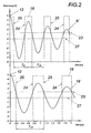
- the coils 7 and 17 interact inductively with the target 2 according to the eddy current principle in order to be able to use a changed signal attenuation in addition to a frequency change for the time measurement. Furthermore, the resonant circuits 9 and 16 are electrically designed such that in these excitation an underdamped oscillation 9 'or 16' is formed. In order to increase the resolution of the time measurement or position measurement, the comparison voltage 23 has a voltage level lying between the heights of the starting voltage 12 and the quiescent voltage 27 of the oscillating circuits 9 and 16, which results in the Figures 2 and 3 can be removed.
- Fig. 4 can be a schematic representation of a use of Fig. 1 shown device to be detected in an electric machine with a magnetic bearing, wherein for the sake of clarity, only the rotor of the electric machine can be seen.
- the rotor serves as a target for the coils 7, 17, 7 'and 17'.
- the coils 7, 17 and 7 ', 17' are each connected via nodes 28 and 28 'with other components, which have been omitted for clarity.
- the other components will be apparent to one skilled in the art with a linkage of the node 28 of Fig. 1 with the nodes 28 and 28 '.
- a parallel construction connected at a node 28 and 28 ' is provided in order to provide on the basis of the parallelization for a faster position measurement can.
- the data of the position measurement to the target 2 can then be supplied to the magnetic bearing control so as to adjust the position of the rotor to the stator in that the magnetic bearing control controls the magnetic bearing.
- a coil 7 or 7 'and a reference coil 17 or 17' are arranged diametrically opposite each other at a distance from the rotor for each radial movement axis of the rotor.
- the after Fig. 1 shown device 1 for measuring the relative movement can also be used for an angle measurement, which is the Fig. 5 can be taken closer.
- the coils 7 and 17 are aligned with respect to a disc-shaped target 2 and interact with this inductively.
- the target 2 has various cake corner-shaped fields 30 and 31, which act inductively on the coils 7 and 17 in different ways, so that upon rotation of the target 2, its relative movement can be detected and recorded by time measurement data from the device.
- the number of fields 30, 31 can be adjusted.
Landscapes
- Physics & Mathematics (AREA)
- General Physics & Mathematics (AREA)
- Transmission And Conversion Of Sensor Element Output (AREA)
- Measurement Of Length, Angles, Or The Like Using Electric Or Magnetic Means (AREA)
Description
Die Erfindung betrifft eine Vorrichtung zur Messung einer Relativbewegung eines Targets, mit einer Steuerung, mit wenigstens einer Spule und wenigstens einer Referenzspule, welche beiden Spulen mit dem Target zur Messung einer Relativbewegung induktiv zusammenwirken, mit einer mit der Spule und/oder mit der Referenzspule verbundenen Kapazität, wobei zumindest Teile der Kapazität und der Spulen wenigstens zwei elektrische Schwingkreise ausbilden, mit wenigstens einer mit der Steuerung verbundenen elektrischen Leistungsversorgung zur Anregung der Schwingkreise und mit einer ein Zeitmessglied, insbesondere TDC Glied, aufweisenden Auswerteschaltung, die mit den Schwingkreisen zur Erzeugung von, von der jeweiligen Anregung der Schwingkreise abhängigen Zeitmessdaten verbunden ist, über die auf die Relativbewegung des Targets rückgeschlossen werden kann.The invention relates to a device for measuring a relative movement of a target, comprising a controller, with at least one coil and at least one reference coil, which inductively cooperate with the target for measuring a relative movement, with one connected to the coil and / or with the reference coil Capacitance, wherein at least parts of the capacitance and the coils form at least two electrical oscillating circuits, with at least one electrical power supply connected to the control for excitation of the oscillating circuits and with an evaluation circuit having a timing element, in particular a TDC element, connected to the oscillating circuits for generating, is connected by the respective excitation of the resonant circuits dependent timing data, on the relative movement of the target can be deduced.
Für eine konstruktiv einfache Vorrichtung zur Messung einer Relativbewegung, insbesondere Positionsmessung, eines Targets ist es aus der
Neben Temperatureinflüssen wirken noch andere negative Störeinflüsse auf die Positionsmessung, was beispielsweise eine Bauteilstreuung darstellen kann. Um solche Einflüsse zu vermeiden sowie auch die Anzahl an Bauteilen zu verringern, schlägt beispielsweise die
Die Erfindung hat sich daher die Aufgabe gestellt, ausgehend vom eingangs geschilderten Stand der Technik eine Vorrichtung und ein Verfahren zur äußerst genauen Messung einer Relativbewegung an Hand von Zeitmessdaten zu schaffen, die bzw. das nicht nur äußerst autark gegenüber jeglichen Störeinflüssen ist, sondern auch eine äußerst genaue sowie wiederholbare Messung gewährleisten kann. Außerdem soll die Vorrichtung vergleichsweise wartungsfreundlich und konstruktiv einfach sein.The invention is therefore based on the object, starting from the above-described prior art to provide a device and a method for extremely accurate measurement of relative movement on the basis of timing data that is not only extremely self-sufficient against any interference, but also a ensure extremely accurate and repeatable measurement. In addition, the device should be comparatively easy to maintain and structurally simple.
Die Erfindung löst die gestellte Aufgabe hinsichtlich der Vorrichtung dadurch, dass die Referenzspule gegenüber dem Target und der Spule derart angeordnet ist, dass die Referenzspule bei einer Relativbewegung des Targets mit einer zur Spule im Wesentlichen entgegengesetzt induktiven Änderung beaufschlagt wird, um anhand einer Differenzbildung der Zeitmessdaten auf die Relativbewegung des Targets rückzuschließen zu können.The invention achieves the stated object with regard to the device in that the reference coil is arranged relative to the target and the coil in such a way that the reference coil is acted upon by a relative movement of the target with a change that is essentially opposite to that of the coil is to be able to draw on the basis of a difference of the time measurement data on the relative movement of the target can.
Insbesondere können Störeinflüsse kompensiert werden, wenn die Referenzspule gegenüber dem Target und der Spule derart angeordnet ist, dass die Referenzspule bei einer Relativbewegung des Targets mit einer zur Spule im Wesentlichen entgegengesetzt induktiven Änderung beaufschlagt wird, um anhand einer Differenzbildung der Zeitmessdaten auf die Relativbewegung des Targets rückzuschließen zu können. Es kann nämlich der technische Effekt genützt werden, dass bei einer nahezu im Betrag ident erfassten Relativbewegung auch Störeinflüsse in nahezu identer Weise in den Messdaten der beiden Schwingkreise über eine Differenzbildung eliminiert werden können. Eine derartige Differenzbildung kann beispielsweise von einer Recheneinheit durchgeführt werden, aber auch andere Mittel zur Berechung eine Differenz sind dafür vorstellbar. Exakte und beispielsweise von Temperatur-, und Umgebungseinflüssen unabhängige Messdaten können daher von einer vergleichsweise konstruktiv einfachen Vorrichtung ermöglicht werden. Außerdem ist damit die Vorrichtung hinsichtlich deren analogen Bauteile vergleichsweise wartungsfreundlich, weil auch alterungsbedingte Störeinflüsse der analogen Bauteile vernachlässigt werden können. Hinzu kommt, dass auch Entkopplungen der Spulen nicht vorgesehen werden müssen, weil durch eine Differenzbildung diese gegenseitigen Störungen ebenso vernachlässigt werden können. Die erfindungsgemäße Vorrichtung zeichnet sich daher nicht nur durch seine konstruktive Einfachheit und Wartungsfreundlichkeit sondern auch durch seine genaue und wiederholbare Messung aus, sondern kann auch durch geringe Störanfälligkeit, wie diese bei Magnetlagern oftmals gefordert wird, universell eingesetzt werden. Vorteilhaft kann hier eine im Wesentlichen entgegengesetzt gleiche induktive Änderung berücksichtigt werden. Außerdem kann der Sachverhalt von Vorteil sein, wenn eine mit der Kapazität zur Bildung eines zweiten Schwingkreises verbindbare Referenzspule vorgesehen ist, wobei der in Abhängigkeit der Steuerung angeregte zweite Schwingkreis wenigstens die Referenzspule und die Kapazität umfasst. Damit können nicht nur einfache Konstruktionsverhältnisse geschaffen werden, weil gegenüber einer Temperatursensorschaltung lediglich ein zusätzliches analoges Bauteil vorgesehen werden muss, sondern es kann auch durch die wiederholte Verwendung einer Vielzahl an analogen Bauteilen der Einfluss der Störeffekte auf die Messung einer Relativbewegung vermindert werden. So kann es nämlich möglich werden, über die bekannten physikalischen Zusammenhänge der Schwingkreise sowie den bekannten elektrischen Kenngrößen der Referenzspule wenigstens kapazitiv bedingte Störeinflüsse auf die Messung der Relativbewegung zu erkennen. Dafür können beispielsweise Zeitmessdaten von Schwingungen zwischen der Spule und der Kapazität einerseits und der Referenzspule und der Kapazität andererseits sowie auch Schwingungen zwischen der Spule, Referenzspule und der Kapazität dienlich sein. Erfindungsgemäß können somit erhöhte Toleranzen in den elektrischen Kenngrößen und/oder selbst eine Alterung der Kapazität bei der erfindungsgemäßen Messung vernachlässigt werden, so dass eine nicht nur vergleichsweise einfach abzugleichende sondern auch gegenüber Störeinflüssen äußerst standfeste Vorrichtung geschaffen werden kann. Die Erfindung kann daher stets dafür sorgen, dass eine genaue und auch wiederholbare Messung, sei es nun zur Positionsmessung oder zur Messung eines Drehwinkels, durchführbar ist. Außerdem ist vorstellbar, dass auf Grundlage der erkannten kapazitiven Störeinflüsse auch der Zustand der Spule besser abgeschätzt werden kann, um damit eine zusätzliche Verbesserung zu schaffen. Hinzu kommt, dass die erfindungsgemäße Vorrichtung vergleichsweise wartungsfreundlich sein kann, weil ein Abgleich der Vorrichtung bzw. der Schwingkreise auf einfache Weise über die Referenzspule möglich ist. Wirkt eine Referenzspule mit dem Target zur Messung induktiv zusammen, so kann die Referenzspule ebenso zur Messung der Relativbewegung herangezogen werden. Außerdem kann mit zwei Messungen, nämlich über den ersten Schwingkreis mit der Spule und über den zweiten Schwingkreis mit der Referenzspule, wie bereits erwähnt, die Wirkung der Störeinflüsse der Kapazität zusätzlich vermindert und damit die Genauigkeit der Messung der Relativbewegung verbessert werden Konstruktive Einfachheit kann sich ergeben, wenn eine in den induktiven Eigenschaften zur Spule im Wesentlichen gleiche Referenzspule vorgesehen ist. Außerdem machen sich die Störeinflüsse bei einer derartigen Ausführung gleichermaßen in beiden Messergebnissen bemerkbar, was eine einfache Differenzbildung gewährleisten kann. Hinzu kommt, dass ein Abgleich der Schwingkreise mit derartigen Spulen vergleichsweise einfach vorgenommen werden kann.In particular, interference effects can be compensated if the reference coil is arranged relative to the target and the coil in such a way that the reference coil is subjected to a relative inductive change relative to the coil during a relative movement of the target, in order to determine the relative movement of the target based on a subtraction of the time measurement data to be able to conclude. Namely, the technical effect can be exploited that with a relative movement almost identical detected disturbances in a nearly identical manner in the measurement data of the two resonant circuits can be eliminated by a difference. Such difference formation can be performed, for example, by a computing unit, but other means for calculating a difference are conceivable. Exact and, for example, temperature and environmental influences independent measurement data can therefore be made possible by a comparatively simple design device. In addition, the device is comparatively easy to maintain in terms of their analog components, because even aging-related interference of the analog components can be neglected. In addition, decoupling of the coils need not be provided, because by subtracting these mutual interference can also be neglected. The device according to the invention is therefore characterized not only by its constructive simplicity and ease of maintenance but also by its accurate and repeatable measurement, but can also be used universally by low susceptibility, as is often required in magnetic bearings. Advantageously, a substantially opposite inductive change can be taken into account here. In addition, the situation may be advantageous if a reference coil which can be connected to the capacitance for forming a second resonant circuit is provided, wherein the second resonant circuit excited as a function of the control comprises at least the reference coil and the capacitance. Not only simple construction conditions are possible be created because compared to a temperature sensor circuit only an additional analog component must be provided, but it can also by the repeated use of a plurality of analog components, the influence of the disturbing effects on the measurement of a relative movement can be reduced. Thus, it may in fact be possible to detect at least capacitively conditioned interference influences on the measurement of the relative movement via the known physical relationships of the resonant circuits as well as the known electrical parameters of the reference coil. For example, timing data of vibrations between the coil and the capacitance on the one hand and the reference coil and the capacitance on the other hand as well as oscillations between the coil, reference coil and the capacitance may be useful for this purpose. Thus, according to the invention, increased tolerances in the electrical parameters and / or even aging of the capacitance in the measurement according to the invention can be neglected, so that a device which is not only comparatively easy to adjust but also extremely resistant to disturbing influences can be created. The invention can therefore always ensure that an accurate and repeatable measurement, be it for position measurement or for measuring a rotation angle, is feasible. In addition, it is conceivable that based on the detected capacitive interference and the condition of the coil can be better estimated, so as to provide additional improvement. In addition, the device according to the invention can be comparatively easy to maintain, because an adjustment of the device or the resonant circuits in a simple manner via the reference coil is possible. If a reference coil interacts inductively with the target for measurement, then the reference coil can likewise be used to measure the relative movement. In addition, with two measurements, namely on the first resonant circuit with the coil and the second resonant circuit with the reference coil, as already mentioned, the effect of the interference of the capacitance is further reduced and thus the accuracy of the measurement of the relative movement can be improved Constructive simplicity may result if a reference coil substantially identical in inductance to the coil is provided. In addition, the disturbing effects in such an embodiment are equally noticeable in both measurement results, which can ensure a simple difference. In addition, an adjustment of the resonant circuits with such coils can be made comparatively easy.
Bilden in Abhängigkeit der Steuerung entweder die Spule oder die Referenzspule einen von der Leistungsversorgung angeregten Schwingkreis mit der Kapazität aus, dann können ohne erheblichen Rechenaufwand in den veränderten Zeitmessdaten des zweiten Schwingkreises kapazitiv bedingte Störeinflüsse erkannt werden. Eine schnelle Messung der Relativbewegung eines Targets kann so erfolgen.If, depending on the control, either the coil or the reference coil forms a resonant circuit excited by the power supply with the capacitance, then capacitively related interference effects can be detected in the changed time measurement data of the second resonant circuit without significant computational effort. A rapid measurement of the relative movement of a target can take place in this way.
Einfache Konstruktionsverhältnisse für eine Zeitmessung an Hand eines Zeitmessglieds ergeben sich, wenn die Auswerteschaltung eine mit den Schwingkreisen und dem Zeitmessglied verbundene Vergleichsstufe umfasst, die ein vom jeweils angeregten Schwingkreis und einer Vergleichsspannung abhängiges Schaltsignal für das Zeitmessglied zur Zeitmessung erzeugt.Simple construction conditions for a time measurement by means of a timing element result when the evaluation circuit comprises a comparator connected to the resonant circuits and the time measuring element, which generates a timing signal dependent on the respectively excited resonant circuit and a comparison voltage for the time measuring element.
Die Genauigkeit in der Messung der Relativbewegung eines Targets kann verbessert werden, wenn wenigstens die Spule mit dem Target nach dem Wirbelstromprinzip induktiv zusammenwirkt. Es kann nämlich dann die mit einer Änderung der Relativlage des Targets einhergehende wirbelstombedingte Änderung der Dämpfung von elektrischen Schwingungen genützt werden, die Auflösung der Zeitmessung und damit auch die Genauigkeit zu verbessern. Dafür muss lediglich von den Schwingkreisen wenigstens der Schwingkreis mit der Spule derart elektrisch ausgelegt sein, dass in diesem bei Anregung eine unterdämpfte Schwingung entsteht, wobei dann die Vergleichsspannung eine zwischen den Höhen der Anrege- und Ruhespannung des Schwingkreises liegende Spannungshöhe aufweisen kann. Es hat sich nämlich herausgestellt, dass im Gegensatz zum Stand der Technik, bei dem Target und Spule induktiv nach dem Permabilitätsprinzip zusammenwirken und sich damit eine Änderung der Relativlage des Targets in einer Änderung der Frequenz der gedämpften Schwingung des Schwingkreises ausdrückt, vorteilhaft die veränderte Dämpfung eine dazu erhöhte Änderung in den Zeitmessdaten genützt werden kann, vorteilhaft die Auflösung der Relativbewegung zu erhöhen. Damit können selbst gegenüber dem Stand der Technik vergleichsweise kleine Änderungen in der Relativlage des Targets von der Vorrichtung noch erfasst werden.The accuracy in the measurement of the relative movement of a target can be improved if at least the coil interacts inductively with the target according to the eddy current principle. It is then possible to use the change in the damping of electrical oscillations associated with a change in the relative position of the target, to improve the resolution of the time measurement and thus also the accuracy. For this purpose, at least the resonant circuit with the coil must be designed so electrically only of the resonant circuits, that in this under excitation vibration creates a subdued vibration, in which case the comparison voltage may have a lying between the heights of the start and rest voltage of the resonant circuit voltage level. It turns out in contrast to the prior art, in which the target and the coil interact inductively according to the permeability principle and thus expresses a change in the relative position of the target in a change in the frequency of the damped oscillation of the resonant circuit, the changed damping advantageously results in an increased change in the time measurement data can be used, advantageous to increase the resolution of the relative movement. Thus even comparatively small changes in the relative position of the target can still be detected by the device even in comparison with the prior art.
Ist die Vergleichsstufe zur Übertragung eines mindestens zwei Signalflanken aufweisenden Schaltsignals mit dem Zeitmessglied verbunden, wobei das Zeitmessglied anhand von Zeitmessungen zwischen zeitlich verschiedenen Flanken Zeitmessdaten erzeugt, so kann damit die Genauigkeit der Messung weiter verbessert werden, indem anhand beispielsweise einer Differenzbildung auch eine Laufzeit der Vergleichsstufe aus den Zeitmessdaten korrigiert werden kann.If the comparison stage for transmitting a switching signal having at least two signal edges is connected to the time measuring element, wherein the time measuring element generates time measurement data based on time measurements between temporally different edges, then the accuracy of the measurement can be further improved by also using, for example, a difference of a running time of the comparison stage can be corrected from the time measurement data.
Vorteilhaft kann sich herausstellen, wenn die Vorrichtung zur Messung der Relativbewegung eines Targets bei einer elektrischen Maschine, die einen Rotor, einen Stator und ein den Rotor am Stator lagerndes Magnetlager mit einer Magnetlagersteuerung aufweist, verwendet wird. Solch eine elektrische Maschine kann beispielsweise ein lagerloser Motor darstellen. Einerseits kann der Rotor als Target für die Vorrichtung zur Positionsmessung dienen und andererseits können die vergleichsweise genauen Daten zur Positionsmessung des Rotors der Magnetlagersteuerung zugeführt werden, wenn die Magnetlagersteuerung unter Berücksichtigung dieser Messung das Magnetlager regelnd ansteuert. Damit kann außerdem eine selbst auf geringe Änderungen in der Relativbewegung des Rotors eine vergleichsweise schnell reagierende Magnetlagersteuerung geschaffen werden.Advantageously, it may turn out that the device for measuring the relative movement of a target in an electric machine having a rotor, a stator and a rotor bearing on the stator magnetic bearing having a magnetic bearing control is used. Such an electric machine may be, for example, a bearingless motor. On the one hand, the rotor can serve as a target for the position measuring device, and on the other hand, the comparatively accurate position measurement data of the rotor can be supplied to the magnetic bearing control, when the magnetic bearing control controls the magnetic bearing in accordance with this measurement. Thus, even a small change in the relative movement of the rotor, a comparatively fast-reacting magnetic bearing control can be created.
Sind für jede radiale Bewegungsachse des Rotors je eine Spule und eine Referenzspule diametral gegenüberliegend mit Abstand zum Rotor angeordnet, dann können radiale Positionsänderungen des Rotors äußerst genau erfasst werden, weil, wie bereits erwähnt, Störeinflüsse, beispielsweise durch eine Wärmebelastung des Motors, einen verminderten Einfluss auf die Positionsmessungen haben können.Are a coil and a reference coil arranged diametrically opposite to each other at a distance from the rotor for each radial movement axis of the rotor, then radial position changes of the rotor can be detected extremely accurately, because, as already mentioned, interference, for example, by a heat load of the engine, may have a reduced influence on the position measurements.
Die Erfindung löst die gestellte Aufgabe hinsichtlich des Verfahrens dadurch, dass bei der Messung eine, von den erfassten Zeitdaten des ersten und des zweiten Schwingkreises abhängige Differenz berücksichtigt wird, wobei wenigstens bei einer Zeitmessung des zweiten Schwingkreises die Referenzspule mit dem Target induktiv zusammenwirkt.The invention solves the stated problem with regard to the method in that during the measurement a difference dependent on the acquired time data of the first and the second resonant circuit is taken into account, wherein at least during a time measurement of the second resonant circuit the reference coil cooperates inductively with the target.
Die Positionsmessung kann besonders verbessert werden, wenn bei der Positionsmessung eine, von den erfassten Zeitdaten des ersten und des zweiten Schwingkreises abhängige Differenz berücksichtigt wird, wobei wenigstens bei einer Zeitmessung des zweiten Schwingkreises die Referenzspule mit dem Target induktiv zusammenwirkt. Vorteilhaft kann insbesondere weiter sein, wenn sich die induktive Änderung der Referenzspule entgegengesetzt zur Spule verhält, weil dann eine erhöhte Auflösung durch verminderte Störeffekte geschaffen werden kann. Außerdem berücksichtigt das Verfahren zur Positionsmessung zusätzlich die Zeitmessdaten einer anderen unterdämpften oder überdämpften, elektrischen Schwingung eines zweiten angeregten Schwingkreises, der sich wenigstens zwischen einer Referenzspule und der Kapazität des einen Schwingkreises ausbildet. Damit kann der Messung zur Relativbewegung eines Targets eine erhöhte Menge an Zeitmessdaten zugeführt werden, die sich mindestens im Einfuß der unterschiedlichen Spulen bzw. der Spule und der Referenzspule unterscheiden. Anhand der gemeinsamen Verwendung der Kapazität kann nun unter Berücksichtigung der bekannten physikalischen Zusammenhänge sowie der bekannten elektrischen Kenngrößen der Bauteile auf eventuelle Störeffekte der Kapazität geschlossen werden. Diese Störeffekte können so bei der Messung der Relativbewegung, die beispielsweise eine Winkel- oder Positionsmessung darstellen kann, berücksichtigt werden, was vergleichsweise abgeglichene sowie gegenüber äußeren Einflüssen autarke Voraussetzungen für ein genaues Verfahren schaffen kann.The position measurement can be improved in particular if, during the position measurement, a difference dependent on the detected time data of the first and the second resonant circuit is taken into account, wherein the reference coil cooperates inductively with the target at least during a time measurement of the second resonant circuit. In particular, it may be advantageous if the inductive change of the reference coil is opposite to the coil, because then an increased resolution can be created by reduced interference effects. In addition, the method for position measurement additionally takes into account the time measurement data of another underdamped or overdamped, electrical oscillation of a second excited resonant circuit, which forms at least between a reference coil and the capacitance of the one resonant circuit. Thus, the measurement can be supplied to the relative movement of a target an increased amount of time measurement data, which differ at least in the presence of the different coils or the coil and the reference coil. Based on the common use of the capacity can now be closed taking into account the known physical relationships and the known electrical characteristics of the components on any parasitic effects of capacity. These disturbing effects can thus be taken into account in the measurement of the relative movement, which can represent, for example, an angle or position measurement, what comparatively balanced as well as against external influences autarkic conditions for an accurate process can create.
Einfache Verfahrensschritte zur Vermeidung von kapazitiven Störeinflüssen können sich ergeben, wenn zur Erzeugung der unterdämpften oder überdämpften, elektrischen Schwingung entweder die Spule oder die Referenzspule einen Schwingkreis mit der Kapazität ausbilden.Simple process steps for avoiding capacitive interference can result if either the coil or the reference coil forms a resonant circuit with the capacitance for generating the underdamped or over-damped electrical oscillation.
In den Figuren ist der Erfindungsgegenstand zur Messung einer Relativbewegung eines Targets anhand eines Ausführungsbeispiels beispielsweise dargestellt. Es zeigen
- Fig. 1
- einen schematischen Aufbau der Vorrichtung zur Positionsmessung,
- Fig. 2
- einen Signalablauf zu unterdämpften Schwingungen der beiden Schwingkreise nach
Fig. 1 , - Fig. 3
- einen Signalablauf zu überdämpften Schwingungen der beiden Schwingkreise nach
Fig. 1 , - Fig. 4
- die Verwendung der nach
Fig. 1 dargestellten Vorrichtung bei einer elektrischen Maschine und - Fig. 5
- eine vereinfachte Ansicht auf die nach
Fig. 1 dargestellte Vorrichtung, die im Gegensatz zurFig. 1 zur Winkelmessung verwendet wird.
- Fig. 1
- a schematic structure of the device for position measurement,
- Fig. 2
- a signal flow to under-damped oscillations of the two oscillating circuits
Fig. 1 . - Fig. 3
- a signal flow to overdamped oscillations of the two oscillating circuits after
Fig. 1 . - Fig. 4
- the use of after
Fig. 1 shown device in an electrical machine and - Fig. 5
- a simplified view of the after
Fig. 1 shown device that in contrast toFig. 1 used for angle measurement.
Die nach
Die insbesondere in den induktiven Eigenschaften zur Spule 7 im Wesentlichen gleiche Referenzspule 17 wirkt ebenso mit dem Target 2 zur Positionsmessung induktiv zusammen. Die Referenzspule kann daher nicht nur zum Abgleich der Vorrichtung sondern auch dazu dienen, positionsabhängige Zeitmessdaten t16' bzw. t16" der Recheneinheit 29 zur Verfügung stellen.The
Insbesondere ist dies von Vorteil, wenn die Referenzspule 17 gegenüber dem Target 2 und der Spule 7 derart angeordnet ist, dass die Referenzspule 17 bei einer Positionsänderung des Targets 2 mit einer, zur Spule 7 im wesentlichen entgegengesetzten induktiven Änderung beaufschlagt wird, was in
Das Zeitmessglied 14 ist derart ausgebildet, dass es an Hand von Schaltsignalen 18 und 19 bzw. 20 und 21 eine Zeitmessung vornehmen kann. Zu diesem Zweck umfasst die Auswerteschaltung 13 eine mit dem Schwingkreis 9, 16 und dem Zeitmessglied 14 verbundene Vergleichsstufe 22, insbesondere einen Komparator. Die Vergleichsstufe 22 erzeugt nun ein vom angeregten Schwingkreis 9, 16 und einer Vergleichsspannung 23 abhängiges Schaltsignal 18 und 19 bzw. 20 und 21, anhand dem das Zeitmessglied 14 auf einfache Weise eine Zeitmessung vornehmen kann.The
Die impulsartigen Schaltsignale 18 und 19 bzw. 20 und 21 weisen steigende Signalflanken 24 und fallende Signalflanken 25 auf, anhand denen das Zeitmessglied 14 Zeitmessdaten t9' bzw. t9" und t16' bzw. t19" erzeugt. Dafür können zwischen den fallenden und/oder steigenden Signalflanken 24 und/oder 25 Zeitmessdaten t9' bzw. t9" bzw. t16' bzw. t16" und/oder t26 herangezogen werden.The pulse-like switching signals 18 and 19 or 20 and 21 have rising signal edges 24 and falling signal edges 25, based on which the
Die Spulen 7 und 17 wirken mit dem Target 2 nach dem Wirbelstromprinzip induktiv zusammen, um eine veränderte Signaldämpfung neben einer Frequenzänderung zur Zeitmessung nützen zu können. Desweiteren sind die Schwingkreise 9 und 16 derart elektrisch ausgelegt, dass in diesen bei Anregung eine unterdämpfte Schwingung 9' bzw. 16' entsteht. Um nun die Auflösung der Zeitmessung bzw. Positionsmessung zu erhöhen, weist die Vergleichsspannung 23 eine zwischen den Höhen der Anregespannung 12 und der Ruhespannung 27 der Schwingkreise 9 bzw. 16 liegende Spannungshöhe auf, was in den
Gemäß
Die nach
Claims (10)
- An apparatus (1) for measuring a relative movement of a target (2), comprising a controller (3), at least one coil (7), and at least one reference coil (17), said two coils (7 and 17) inductively interacting with the target (2) for measuring a relative movement, further comprising a capacitor (8) connected to the coil (7) and/or to the reference coil (17), wherein at least parts of the capacitor (8) and the coils (7, 17) form at least two electric oscillating circuits (9, 16), further comprising at least one electric power supply (10) for exciting the oscillating circuits (9, 16), said power supply being connected to the controller (3), and an evaluation circuit (13), which comprises a time measuring member (14), more particularly a TDC member, and is connected to the oscillating circuits (9, 16) in order to generate time measurement data (t9', t9" and t16', t16") that are dependent on the respective excitation of the oscillating circuits (9, 16), said data allowing a conclusion to be drawn on the relative movement of the target (2), characterized in that the reference coil (17) is arranged with respect to the target (2) and the coil (7) in such a way that during a relative movement of the target (2) the reference coil (17) is subjected to a substantially opposite inductive change in order to enable drawing conclusions on the relative movement of the target (2) by forming the difference between the time measurement data (t9', t9" and t16', t16").
- An apparatus according to claim 1, characterized in that the reference coil (17) is formed with respect to its inductive properties substantially similar to the coil (7).
- An apparatus according to claim 1 or 2, characterized in that depending on the controller (3) either the coil (7) or the reference coil (17) forms with the capacitor (8) an oscillating circuit (9, 16) excited by the power supply.
- An apparatus according to claim 1, 2 or 3, characterized in that the evaluation circuit (13) comprises a comparison module (22) which is connected to the oscillating circuits (9, 16) and the time measuring member (14), which comparison module generates a switching signal (18, 19 or 20, 21) for the time measuring member (14), which switching signal is dependent on the respectively excited oscillating circuit (9, 16) and a reference voltage (23).
- An apparatus according to claim 4, characterized in that at least the coil (7) inductively interacts with the target (2) according to the eddy current principle, and from the oscillating circuits (9, 16) at least the oscillating circuit (9) with the coil (7) is electrically formed in such a way that an underdamped oscillation (9') is generated therein upon excitation, wherein the reference voltage (23) has a voltage level disposed between the levels of the excitation and quiescent voltage (12 and 27) of the oscillating circuit (7).
- An apparatus according to claim 4 or 5, characterized in that the comparison module (22) is connected to the time measuring member (14) for transmission of a switching signal (18, 19 or 20, 21) having at least two signal edges (24, 25), wherein the time measuring member (14) generates time measurement data on the basis of time measurements between temporally different edges (24, 25).
- The use of the apparatus for measuring the relative movement of a target (2) according to one of the claims 1 to 6 in an electric machine, especially a bearing-free motor, which electric machine comprises a rotor, a stator and a magnetic bearing with a magnetic bearing controller, which magnetic bearing mounts the rotor on the stator, wherein the rotor is used at least partly as a target (2) for the apparatus (1) for position measurement and the magnetic bearing controller triggers the magnetic bearing in a controlling manner by taking said measurement of the apparatus (1) into account.
- The use according to claim 7, characterized in that for each radial movement axis of the rotor a respective coil (7, 7') and a reference coil (17, 17') are arranged in a diametrically opposite manner with distance from the rotor.
- A method for measuring a relative movement of a target (2), in which time measurement data (t9', t9") are detected on the basis of an underdamped or overdamped electric oscillation (9', 9") of an excited oscillating circuit (9), which is formed at least between a capacitor (8) and a coil (7) inductively interacting with the target (2), via which time measurement data conclusions can be drawn on the relative movement of the target (2), wherein for the measurement the time measurement data (t16', t16") of another underdamped or overdamped electric oscillation (16', 16") of a second excited oscillating circuit (16) are additionally considered, which is formed at least between a reference coil (17) and the capacitor (8) of the one oscillating circuit (9), characterized in that during the measurement a difference is considered which is dependent on the detected time data (t9', t16' or t9", t16") of the first and the second oscillating circuit (9, 16), wherein the reference coil (17) inductively interacts with the target (2) at least during a time measurement of the second oscillating circuit (16).
- A method according to claim 9, characterized in that either the coil (7) or the reference coil (17) forms an oscillating circuit (9, 16) with the capacitor (8) for generating the underdamped or overdamped electric oscillation (9', 16' or 9", 16").
Applications Claiming Priority (2)
| Application Number | Priority Date | Filing Date | Title |
|---|---|---|---|
| ATA665/2009A AT508189B1 (en) | 2009-04-30 | 2009-04-30 | DEVICE AND METHOD FOR MEASURING A RELATIVE MOTION OF A TARGET |
| PCT/AT2010/000135 WO2010124310A2 (en) | 2009-04-30 | 2010-04-29 | Apparatus and method for measuring a relative movement of a target |
Publications (2)
| Publication Number | Publication Date |
|---|---|
| EP2425207A2 EP2425207A2 (en) | 2012-03-07 |
| EP2425207B1 true EP2425207B1 (en) | 2015-09-30 |
Family
ID=42791136
Family Applications (1)
| Application Number | Title | Priority Date | Filing Date |
|---|---|---|---|
| EP10720240.0A Active EP2425207B1 (en) | 2009-04-30 | 2010-04-29 | Apparatus and method for measuring a relative movement of a target |
Country Status (3)
| Country | Link |
|---|---|
| EP (1) | EP2425207B1 (en) |
| AT (1) | AT508189B1 (en) |
| WO (1) | WO2010124310A2 (en) |
Families Citing this family (2)
| Publication number | Priority date | Publication date | Assignee | Title |
|---|---|---|---|---|
| AT511602B1 (en) * | 2011-12-30 | 2013-01-15 | Johannes Kepler Uni | DEVICE AND METHOD FOR MEASURING A RELATIVE MOTION OF A TARGET |
| DE102013208600A1 (en) * | 2013-05-10 | 2014-11-13 | Robert Bosch Gmbh | Exciter device for an angular position sensor |
Family Cites Families (5)
| Publication number | Priority date | Publication date | Assignee | Title |
|---|---|---|---|---|
| US4644570A (en) * | 1985-09-20 | 1987-02-17 | Bitronics, Inc. | Sensor amplification and enhancement apparatus using digital techniques |
| DE4237879A1 (en) * | 1992-11-10 | 1994-05-11 | Bosch Gmbh Robert | Evaluation circuit for an inductive sensor |
| DE10130572B4 (en) * | 2001-06-27 | 2010-01-07 | Ifm Electronic Gmbh | Inductive displacement sensor for determining the position of an influencing element and method for determining the position of an influencing element with an inductive displacement sensor |
| DE10322447A1 (en) * | 2003-05-19 | 2004-12-09 | Bayerische Motoren Werke Ag | Position measurement device for linearly or rotationally moving components, has twin coil arrangement and electrical oscillation circuit that permits measurement of time response of output signal to input voltage pulse |
| DE102004032258B4 (en) * | 2004-06-11 | 2018-05-30 | Balluff Gmbh | Inductive proximity sensor |
-
2009
- 2009-04-30 AT ATA665/2009A patent/AT508189B1/en not_active IP Right Cessation
-
2010
- 2010-04-29 EP EP10720240.0A patent/EP2425207B1/en active Active
- 2010-04-29 WO PCT/AT2010/000135 patent/WO2010124310A2/en not_active Ceased
Also Published As
| Publication number | Publication date |
|---|---|
| AT508189A1 (en) | 2010-11-15 |
| EP2425207A2 (en) | 2012-03-07 |
| WO2010124310A2 (en) | 2010-11-04 |
| AT508189B1 (en) | 2012-04-15 |
| WO2010124310A3 (en) | 2010-12-23 |
Similar Documents
| Publication | Publication Date | Title |
|---|---|---|
| EP1419365B1 (en) | Device and method for reading out a differential capacitor comprising a first and second partial capacitor | |
| DE69631691T2 (en) | GAME MEASURING SYSTEM | |
| DE102007002705B4 (en) | Device and method for detecting a direction reversal of a relative movement | |
| DE102007007551A1 (en) | Inductive proximity sensor | |
| DE202018006650U1 (en) | Electronic device with inductive sensor | |
| EP3030862B1 (en) | Circuit arrangement and method for controlling a displacement measurement sensor | |
| DE2940083A1 (en) | FREQUENCY GENERATOR | |
| EP2425207B1 (en) | Apparatus and method for measuring a relative movement of a target | |
| DE102016209366A1 (en) | Method and device for calibrating a positioner system | |
| DE102014113545A1 (en) | Device and method for monitoring a process variable of a medium | |
| DE69112398T2 (en) | METHOD AND DEVICE FOR CHECKING COINS. | |
| DE2649621C2 (en) | Device for measuring the speed of a vehicle | |
| DE69114479T2 (en) | LOCATION DETECTOR. | |
| DE102017128472A1 (en) | Inductive proximity switch and method of operating an inductive proximity switch | |
| DE102018105234B4 (en) | Method for operating a capacitive pressure measuring device | |
| EP3117182A1 (en) | Method for optimizing the switch-on time of a coriolis gyroscope and coriolis gyroscope suitable therefor | |
| DE102017128471A1 (en) | Inductive proximity switch and method of operating an inductive proximity switch | |
| EP2291615B1 (en) | Inductive sensor | |
| DE3115195C2 (en) | ||
| DE10344983B3 (en) | Method for charging an actively shielded superconducting NMR magnet | |
| DE102022133045B4 (en) | compensation method for resonance detection | |
| EP4513199B1 (en) | Proximity switch for measuring the speed of a measurement object | |
| EP2798312B1 (en) | Apparatus and method for measuring a relative movement of a target | |
| DE102008064544A1 (en) | Disk like transmitter e.g. permanent magnetic element, position and path measuring system, has evaluation device with subunit, which calculates quotients based on sensor signals and determines position of transmitter based on calculation | |
| EP3557188A1 (en) | Magnetized piston rod for measuring displacement |
Legal Events
| Date | Code | Title | Description |
|---|---|---|---|
| PUAI | Public reference made under article 153(3) epc to a published international application that has entered the european phase |
Free format text: ORIGINAL CODE: 0009012 |
|
| 17P | Request for examination filed |
Effective date: 20111130 |
|
| AK | Designated contracting states |
Kind code of ref document: A2 Designated state(s): AT BE BG CH CY CZ DE DK EE ES FI FR GB GR HR HU IE IS IT LI LT LU LV MC MK MT NL NO PL PT RO SE SI SK SM TR |
|
| DAX | Request for extension of the european patent (deleted) | ||
| GRAP | Despatch of communication of intention to grant a patent |
Free format text: ORIGINAL CODE: EPIDOSNIGR1 |
|
| INTG | Intention to grant announced |
Effective date: 20150414 |
|
| GRAS | Grant fee paid |
Free format text: ORIGINAL CODE: EPIDOSNIGR3 |
|
| GRAA | (expected) grant |
Free format text: ORIGINAL CODE: 0009210 |
|
| AK | Designated contracting states |
Kind code of ref document: B1 Designated state(s): AT BE BG CH CY CZ DE DK EE ES FI FR GB GR HR HU IE IS IT LI LT LU LV MC MK MT NL NO PL PT RO SE SI SK SM TR |
|
| RAP1 | Party data changed (applicant data changed or rights of an application transferred) |
Owner name: AUSTRIAN CENTER OF COMPETENCE IN MECHATRONICS GMBH |
|
| REG | Reference to a national code |
Ref country code: CH Ref legal event code: EP Ref country code: GB Ref legal event code: FG4D Free format text: NOT ENGLISH |
|
| REG | Reference to a national code |
Ref country code: AT Ref legal event code: REF Ref document number: 752683 Country of ref document: AT Kind code of ref document: T Effective date: 20151015 |
|
| REG | Reference to a national code |
Ref country code: IE Ref legal event code: FG4D Free format text: LANGUAGE OF EP DOCUMENT: GERMAN |
|
| REG | Reference to a national code |
Ref country code: DE Ref legal event code: R096 Ref document number: 502010010384 Country of ref document: DE |
|
| REG | Reference to a national code |
Ref country code: DE Ref legal event code: R082 Ref document number: 502010010384 Country of ref document: DE Representative=s name: WOLF & WOLF PATENT- UND RECHTSANWAELTE, DE Ref country code: DE Ref legal event code: R081 Ref document number: 502010010384 Country of ref document: DE Owner name: LINZ CENTER OF MECHATRONICS GMBH, AT Free format text: FORMER OWNER: AUSTRIAN CENTER OF COMPETENCE IN MECHATRONICS GMBH, LINZ, AT Ref country code: DE Ref legal event code: R082 Ref document number: 502010010384 Country of ref document: DE Representative=s name: WOLF & WOLF PATENT- UND RECHTSANWALTSGESELLSCH, DE Ref country code: DE Ref legal event code: R082 Ref document number: 502010010384 Country of ref document: DE Representative=s name: WOLF & WOLF PATENT- UND RECHTSANWAELTE GBR, DE |
|
| REG | Reference to a national code |
Ref country code: CH Ref legal event code: PFUS Owner name: LINZ CENTER OF MECHATRONICS GMBH, AT Free format text: FORMER OWNER: AUSTRIAN CENTER OF COMPETENCE IN MECHATRONICS GMBH, AT Ref country code: CH Ref legal event code: NV Representative=s name: ISLER AND PEDRAZZINI AG, CH |
|
| PG25 | Lapsed in a contracting state [announced via postgrant information from national office to epo] |
Ref country code: NO Free format text: LAPSE BECAUSE OF FAILURE TO SUBMIT A TRANSLATION OF THE DESCRIPTION OR TO PAY THE FEE WITHIN THE PRESCRIBED TIME-LIMIT Effective date: 20151230 Ref country code: LV Free format text: LAPSE BECAUSE OF FAILURE TO SUBMIT A TRANSLATION OF THE DESCRIPTION OR TO PAY THE FEE WITHIN THE PRESCRIBED TIME-LIMIT Effective date: 20150930 Ref country code: LT Free format text: LAPSE BECAUSE OF FAILURE TO SUBMIT A TRANSLATION OF THE DESCRIPTION OR TO PAY THE FEE WITHIN THE PRESCRIBED TIME-LIMIT Effective date: 20150930 Ref country code: FI Free format text: LAPSE BECAUSE OF FAILURE TO SUBMIT A TRANSLATION OF THE DESCRIPTION OR TO PAY THE FEE WITHIN THE PRESCRIBED TIME-LIMIT Effective date: 20150930 Ref country code: GR Free format text: LAPSE BECAUSE OF FAILURE TO SUBMIT A TRANSLATION OF THE DESCRIPTION OR TO PAY THE FEE WITHIN THE PRESCRIBED TIME-LIMIT Effective date: 20151231 |
|
| REG | Reference to a national code |
Ref country code: NL Ref legal event code: MP Effective date: 20150930 |
|
| REG | Reference to a national code |
Ref country code: LT Ref legal event code: MG4D |
|
| PG25 | Lapsed in a contracting state [announced via postgrant information from national office to epo] |
Ref country code: HR Free format text: LAPSE BECAUSE OF FAILURE TO SUBMIT A TRANSLATION OF THE DESCRIPTION OR TO PAY THE FEE WITHIN THE PRESCRIBED TIME-LIMIT Effective date: 20150930 Ref country code: SE Free format text: LAPSE BECAUSE OF FAILURE TO SUBMIT A TRANSLATION OF THE DESCRIPTION OR TO PAY THE FEE WITHIN THE PRESCRIBED TIME-LIMIT Effective date: 20150930 |
|
| RAP2 | Party data changed (patent owner data changed or rights of a patent transferred) |
Owner name: LINZ CENTER OF MECHATRONICS GMBH |
|
| REG | Reference to a national code |
Ref country code: GB Ref legal event code: 732E Free format text: REGISTERED BETWEEN 20160317 AND 20160323 |
|
| REG | Reference to a national code |
Ref country code: FR Ref legal event code: PLFP Year of fee payment: 7 |
|
| PG25 | Lapsed in a contracting state [announced via postgrant information from national office to epo] |
Ref country code: CZ Free format text: LAPSE BECAUSE OF FAILURE TO SUBMIT A TRANSLATION OF THE DESCRIPTION OR TO PAY THE FEE WITHIN THE PRESCRIBED TIME-LIMIT Effective date: 20150930 Ref country code: IS Free format text: LAPSE BECAUSE OF FAILURE TO SUBMIT A TRANSLATION OF THE DESCRIPTION OR TO PAY THE FEE WITHIN THE PRESCRIBED TIME-LIMIT Effective date: 20160130 Ref country code: SK Free format text: LAPSE BECAUSE OF FAILURE TO SUBMIT A TRANSLATION OF THE DESCRIPTION OR TO PAY THE FEE WITHIN THE PRESCRIBED TIME-LIMIT Effective date: 20150930 Ref country code: NL Free format text: LAPSE BECAUSE OF FAILURE TO SUBMIT A TRANSLATION OF THE DESCRIPTION OR TO PAY THE FEE WITHIN THE PRESCRIBED TIME-LIMIT Effective date: 20150930 Ref country code: ES Free format text: LAPSE BECAUSE OF FAILURE TO SUBMIT A TRANSLATION OF THE DESCRIPTION OR TO PAY THE FEE WITHIN THE PRESCRIBED TIME-LIMIT Effective date: 20150930 Ref country code: EE Free format text: LAPSE BECAUSE OF FAILURE TO SUBMIT A TRANSLATION OF THE DESCRIPTION OR TO PAY THE FEE WITHIN THE PRESCRIBED TIME-LIMIT Effective date: 20150930 |
|
| PG25 | Lapsed in a contracting state [announced via postgrant information from national office to epo] |
Ref country code: PL Free format text: LAPSE BECAUSE OF FAILURE TO SUBMIT A TRANSLATION OF THE DESCRIPTION OR TO PAY THE FEE WITHIN THE PRESCRIBED TIME-LIMIT Effective date: 20150930 Ref country code: RO Free format text: LAPSE BECAUSE OF FAILURE TO SUBMIT A TRANSLATION OF THE DESCRIPTION OR TO PAY THE FEE WITHIN THE PRESCRIBED TIME-LIMIT Effective date: 20150930 Ref country code: PT Free format text: LAPSE BECAUSE OF FAILURE TO SUBMIT A TRANSLATION OF THE DESCRIPTION OR TO PAY THE FEE WITHIN THE PRESCRIBED TIME-LIMIT Effective date: 20160201 |
|
| REG | Reference to a national code |
Ref country code: DE Ref legal event code: R097 Ref document number: 502010010384 Country of ref document: DE |
|
| PLBE | No opposition filed within time limit |
Free format text: ORIGINAL CODE: 0009261 |
|
| STAA | Information on the status of an ep patent application or granted ep patent |
Free format text: STATUS: NO OPPOSITION FILED WITHIN TIME LIMIT |
|
| PG25 | Lapsed in a contracting state [announced via postgrant information from national office to epo] |
Ref country code: BE Free format text: LAPSE BECAUSE OF NON-PAYMENT OF DUE FEES Effective date: 20160430 Ref country code: DK Free format text: LAPSE BECAUSE OF FAILURE TO SUBMIT A TRANSLATION OF THE DESCRIPTION OR TO PAY THE FEE WITHIN THE PRESCRIBED TIME-LIMIT Effective date: 20150930 |
|
| 26N | No opposition filed |
Effective date: 20160701 |
|
| PG25 | Lapsed in a contracting state [announced via postgrant information from national office to epo] |
Ref country code: SI Free format text: LAPSE BECAUSE OF FAILURE TO SUBMIT A TRANSLATION OF THE DESCRIPTION OR TO PAY THE FEE WITHIN THE PRESCRIBED TIME-LIMIT Effective date: 20150930 |
|
| PG25 | Lapsed in a contracting state [announced via postgrant information from national office to epo] |
Ref country code: LU Free format text: LAPSE BECAUSE OF FAILURE TO SUBMIT A TRANSLATION OF THE DESCRIPTION OR TO PAY THE FEE WITHIN THE PRESCRIBED TIME-LIMIT Effective date: 20160429 |
|
| REG | Reference to a national code |
Ref country code: IE Ref legal event code: MM4A |
|
| REG | Reference to a national code |
Ref country code: FR Ref legal event code: PLFP Year of fee payment: 8 |
|
| PG25 | Lapsed in a contracting state [announced via postgrant information from national office to epo] |
Ref country code: IE Free format text: LAPSE BECAUSE OF NON-PAYMENT OF DUE FEES Effective date: 20160429 |
|
| REG | Reference to a national code |
Ref country code: AT Ref legal event code: PC Ref document number: 752683 Country of ref document: AT Kind code of ref document: T Owner name: LINZ CENTER OF MECHATRONICS GMBH, AT Effective date: 20180126 |
|
| REG | Reference to a national code |
Ref country code: FR Ref legal event code: PLFP Year of fee payment: 9 |
|
| PG25 | Lapsed in a contracting state [announced via postgrant information from national office to epo] |
Ref country code: CY Free format text: LAPSE BECAUSE OF FAILURE TO SUBMIT A TRANSLATION OF THE DESCRIPTION OR TO PAY THE FEE WITHIN THE PRESCRIBED TIME-LIMIT Effective date: 20150930 Ref country code: HU Free format text: LAPSE BECAUSE OF FAILURE TO SUBMIT A TRANSLATION OF THE DESCRIPTION OR TO PAY THE FEE WITHIN THE PRESCRIBED TIME-LIMIT; INVALID AB INITIO Effective date: 20100429 Ref country code: SM Free format text: LAPSE BECAUSE OF FAILURE TO SUBMIT A TRANSLATION OF THE DESCRIPTION OR TO PAY THE FEE WITHIN THE PRESCRIBED TIME-LIMIT Effective date: 20150930 |
|
| PG25 | Lapsed in a contracting state [announced via postgrant information from national office to epo] |
Ref country code: MK Free format text: LAPSE BECAUSE OF FAILURE TO SUBMIT A TRANSLATION OF THE DESCRIPTION OR TO PAY THE FEE WITHIN THE PRESCRIBED TIME-LIMIT Effective date: 20150930 Ref country code: TR Free format text: LAPSE BECAUSE OF FAILURE TO SUBMIT A TRANSLATION OF THE DESCRIPTION OR TO PAY THE FEE WITHIN THE PRESCRIBED TIME-LIMIT Effective date: 20150930 Ref country code: MC Free format text: LAPSE BECAUSE OF FAILURE TO SUBMIT A TRANSLATION OF THE DESCRIPTION OR TO PAY THE FEE WITHIN THE PRESCRIBED TIME-LIMIT Effective date: 20150930 Ref country code: MT Free format text: LAPSE BECAUSE OF FAILURE TO SUBMIT A TRANSLATION OF THE DESCRIPTION OR TO PAY THE FEE WITHIN THE PRESCRIBED TIME-LIMIT Effective date: 20150930 |
|
| PG25 | Lapsed in a contracting state [announced via postgrant information from national office to epo] |
Ref country code: BG Free format text: LAPSE BECAUSE OF FAILURE TO SUBMIT A TRANSLATION OF THE DESCRIPTION OR TO PAY THE FEE WITHIN THE PRESCRIBED TIME-LIMIT Effective date: 20150930 |
|
| PGFP | Annual fee paid to national office [announced via postgrant information from national office to epo] |
Ref country code: IT Payment date: 20210430 Year of fee payment: 12 |
|
| PGFP | Annual fee paid to national office [announced via postgrant information from national office to epo] |
Ref country code: AT Payment date: 20210420 Year of fee payment: 12 |
|
| REG | Reference to a national code |
Ref country code: AT Ref legal event code: MM01 Ref document number: 752683 Country of ref document: AT Kind code of ref document: T Effective date: 20220429 |
|
| PG25 | Lapsed in a contracting state [announced via postgrant information from national office to epo] |
Ref country code: AT Free format text: LAPSE BECAUSE OF NON-PAYMENT OF DUE FEES Effective date: 20220429 |
|
| PG25 | Lapsed in a contracting state [announced via postgrant information from national office to epo] |
Ref country code: IT Free format text: LAPSE BECAUSE OF NON-PAYMENT OF DUE FEES Effective date: 20220429 |
|
| P01 | Opt-out of the competence of the unified patent court (upc) registered |
Effective date: 20230526 |
|
| PGFP | Annual fee paid to national office [announced via postgrant information from national office to epo] |
Ref country code: GB Payment date: 20240423 Year of fee payment: 15 |
|
| PGFP | Annual fee paid to national office [announced via postgrant information from national office to epo] |
Ref country code: DE Payment date: 20240418 Year of fee payment: 15 |
|
| PGFP | Annual fee paid to national office [announced via postgrant information from national office to epo] |
Ref country code: CH Payment date: 20240501 Year of fee payment: 15 |
|
| PGFP | Annual fee paid to national office [announced via postgrant information from national office to epo] |
Ref country code: FR Payment date: 20240419 Year of fee payment: 15 |
|
| REG | Reference to a national code |
Ref country code: DE Ref legal event code: R119 Ref document number: 502010010384 Country of ref document: DE |
|
| REG | Reference to a national code |
Ref country code: CH Ref legal event code: H13 Free format text: ST27 STATUS EVENT CODE: U-0-0-H10-H13 (AS PROVIDED BY THE NATIONAL OFFICE) Effective date: 20251125 |
|
| GBPC | Gb: european patent ceased through non-payment of renewal fee |
Effective date: 20250429 |
|
| PG25 | Lapsed in a contracting state [announced via postgrant information from national office to epo] |
Ref country code: DE Free format text: LAPSE BECAUSE OF NON-PAYMENT OF DUE FEES Effective date: 20251104 |
|
| PG25 | Lapsed in a contracting state [announced via postgrant information from national office to epo] |
Ref country code: GB Free format text: LAPSE BECAUSE OF NON-PAYMENT OF DUE FEES Effective date: 20250429 |
|
| PG25 | Lapsed in a contracting state [announced via postgrant information from national office to epo] |
Ref country code: FR Free format text: LAPSE BECAUSE OF NON-PAYMENT OF DUE FEES Effective date: 20250430 |
|
| PG25 | Lapsed in a contracting state [announced via postgrant information from national office to epo] |
Ref country code: CH Free format text: LAPSE BECAUSE OF NON-PAYMENT OF DUE FEES Effective date: 20250430 |