EP2425151B1 - Courroie en v dentée double pour entraînement à vitesse variable - Google Patents
Courroie en v dentée double pour entraînement à vitesse variable Download PDFInfo
- Publication number
- EP2425151B1 EP2425151B1 EP10716131.7A EP10716131A EP2425151B1 EP 2425151 B1 EP2425151 B1 EP 2425151B1 EP 10716131 A EP10716131 A EP 10716131A EP 2425151 B1 EP2425151 B1 EP 2425151B1
- Authority
- EP
- European Patent Office
- Prior art keywords
- belt
- cogs
- cog
- profile
- roots
- Prior art date
- Legal status (The legal status is an assumption and is not a legal conclusion. Google has not performed a legal analysis and makes no representation as to the accuracy of the status listed.)
- Active
Links
Images
Classifications
-
- F—MECHANICAL ENGINEERING; LIGHTING; HEATING; WEAPONS; BLASTING
- F16—ENGINEERING ELEMENTS AND UNITS; GENERAL MEASURES FOR PRODUCING AND MAINTAINING EFFECTIVE FUNCTIONING OF MACHINES OR INSTALLATIONS; THERMAL INSULATION IN GENERAL
- F16G—BELTS, CABLES, OR ROPES, PREDOMINANTLY USED FOR DRIVING PURPOSES; CHAINS; FITTINGS PREDOMINANTLY USED THEREFOR
- F16G5/00—V-belts, i.e. belts of tapered cross-section
- F16G5/20—V-belts, i.e. belts of tapered cross-section with a contact surface of special shape, e.g. toothed
Definitions
- This invention relates generally to a double-cogged V-belt, more particularly to a double-cogged V-belt with aligned upper and lower cogs having a particular combination of cog profiles, and specifically such a V-belt adapted for a variable speed transmission.
- variable speed transmission the belt plays an important role in the operation of variable speed power transmission systems or drives, such as used in scooters, motorcycles, snowmobiles, all-terrain vehicles, cars and industrial applications.
- VST variable speed transmission
- the belt is a flexible element which connects two pairs of sheaves through friction to transmit power from the driving shaft to the driven shaft.
- Each pair of sheaves includes a fixed sheave and a movable sheave.
- the speed and torque ratio may be changed.
- the belt sustains extreme longitudinal tension and bending and transverse compression.
- contradictory requirements namely high longitudinal flexibility but high transverse stiffness while maintaining proper side contact.
- V-belts for VST generally need to be relatively wider and thinner than V-belts for fixed drives in order to accommodate a range of movement radially inward and outward in the variable sheaves.
- the resulting relatively wide aspect ratio of VST belts makes transverse stiffness more difficult to achieve, especially with the shifting movements placing increased transverse loads on the belt.
- the aspect ratio of the belt can be such that sufficient transverse stiffness is more easily achieved.
- U.S. Pat. No. 6,620,068 discloses a raw-edge double-cogged V-belt for variable speed drives having curvilinear cogs on the inside and outside. The number of outside cogs are twice the number of and aligned with the inside cogs.
- JP 2002-089631A discloses a dual cog V-belt with more upper cogs than lower cogs, but less than twice as many so that the alignment or phase of the upper and lower cogs is variable.
- U.S. Pat. No. 1,890,080 discloses staggered rounded cogs of equal size and shape.
- U.S. Pat. No. 2,699,685 discloses staggered blocky-shaped cogs of equal size and shape with the grooves of one section vertically opposite the cogs of the other section in order to avoid weak spots and so that the thickness of the belt is the same all over.
- JP 2002-031192A discloses a variation on a staggered double-cogged V-belt for VST applications wherein equal-numbered upper and lower cogs are not exactly in phase or out of phase, but phase shifted an amount somewhere in between, preferably from a tenth to half of the pitch. That publication teaches that lower and upper cog parts should not align or correspond so the belt thickness does not get extremely small thus preventing stress concentration and early crack initiation in that region.
- Finite element method (“FEM”) analysis was apparently used to design an improved phase-shifted staggered profile and to confirm this effect. Increased phase shift up to half a pitch resulted in reduced root cracking.
- the present invention is directed to a V-belt as recited in the claims.
- the present invention is directed to a double-cogged V-belt with the upper and lower cog profiles symmetric and having lines (“L") and arcs ("A") connected according to a sequence beginning from the center of a root and extending to the center of an adjacent cog, the sequence being L1-A1-L2-A2-L3 for the upper profile and L4-A3-L5-A4-L6 for the lower profile, and with the sum of the length of L1 plus the radius of A1 equal to or within 20% of the sum of the length of L4 plus the radius of A3, and with at least one upper root and one lower root substantially aligned with each other.
- L lines
- A arcs
- the upper and lower pitches may be equal and all the roots substantially aligned. In another embodiment there may be more upper cogs than lower cogs.
- the ratio of the number of upper to lower cogs may be up to 1.3, or from 1.1 to 1.3.
- arcs and lines may be connected tangentially.
- lines L1 and L2 may connect tangentially with arc A1
- said lines L4 and L5 may connect tangentially with arc A3.
- L1, L3, L4, and L6 connect tangentially with their mirror images at the centers of the roots and centers of the cog tips, so that the roots and tips are flat and smooth.
- the flanks of the cogs may be at an angle so that the included angle between opposing cog flanks is in the range of from about 10 to about 30 degrees.
- Embodiments of the invention are particularly suited to V-belts for variable speed transmissions when the top width of the belt is about twice the overall thickness of the belt. It may also be advantageous for the pulley contact faces of the V-belt to have a first planar surface disposed at a first angle for engaging a sheave and a cooperating second planar surface disposed at a second angle that does not engage with a sheave surface.
- the inventive belt exhibits various advantages over prior art double-cogged V-belt designs. Flexibility is improved without significantly increasing susceptibility to root cracking, and improved crack resistance is seen in the lower cog roots especially. Consistency of performance is improved.
- a V-belt may be adapted with a single set of lower cogs on the inside 40 of the belt.
- a double cogged V-belt design in which additional cogs are added on the upper or back side 30 of a belt, may be used to further increase transversal stiffness while still maintaining high flexibility and suitable contact area.
- each cog is symmetric about the cog center and is a combination of straight line segments and arcs.
- a nomenclature system is used herein and in the claims to help identify and categorize profiles found in the art and embodiments of the present invention.
- "A" represents an arc that is a component of a profile and "L” represents a line. If adjacent arcs and/or lines are connected, but not tangentially connected, a "+" sign is used to indicate the connection.
- Another way to describe non-tangentially connected arc and/or line segments is that the first derivative is not continuous at the point of connection.
- a sequence numeral may be used in association with the letters L and/or A to differentiate a number of lines or arcs in a sequence defining a given profile.
- L1 may refer to the first line segment in a profile, and depending on the context, “L1” may also refer to the length of that line segment.
- A1 may refer to the first arc in a sequence representing a profile, and "R1” may refer to the radius of that arc.
- the invention is directed to double-cogged V-belts with an upper cog profile having the sequence LALAL, and a lower cog profile also having the sequence LALAL.
- the root or valley, represented by the first L in both the upper and lower profile is substantially flat.
- the flank of the cog in both upper and lower profiles is flat and the tip of the cog in both upper and lower profiles is flat.
- Each flat portion is connected by an arc.
- substantially “flat” is meant that the profile portion is straight when the belt is laid out flat, which is called the "rack" form of the profile.
- a flat segment may actually follow the curvature of the cord line or the natural curvature of the belt.
- the upper cog profile may be represented with the sequence L1-A1-L2-A2-L3 from the center of a root to the center of an adjacent cog.
- the lower cog profile may be represented with the sequence L4-A3-L5-A4-L6 from the center of a root to the center of an adjacent cog.
- the embodiment of FIG. 3 illustrates the location and connections between these arcs and lines forming the cog profiles of a double-cogged V-belt.
- the invention is directed to such double-cogged V-belts with at least one upper root aligned with at least one corresponding lower root.
- the sum of the length of L1 plus the radius of A1 is equal to or within 20% of the sum of the length of L4 plus the radius of A3.
- L4 may be of zero length.
- L2 may be of zero length in specific embodiments.
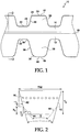
- double-cogged V-belt 10 includes tensile layer 16 sandwiched between overcord layer 14 and undercord layer 12 making up the main body of the belt.
- the double-cogged V-belt shown in FIG's 1-3 also has lower cogs 18 and upper cogs 20 protruding from the main belt body.
- Upper cogs 20 include tip 17, flank 26 and valley or root 22.
- lower cogs 18 include tip 19, flank 36 and root 32.
- the double-cogged V-belt of FIG. 1 and FIG. 3 is drawn in rack form, i.e., flat and without curvature of the tensile layer.
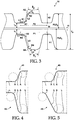
- FIG. 2 shows a section of the V-belt of FIG. 1 , cut along the line 2-2 in FIG. 1 .
- the overall belt width is called the top width and identified as "TW".
- the overall thickness of the belt is identified as "T 0 ".
- the pulley contact faces or side surfaces 42 of the V-belt are cut at an angle ⁇ /2 with respect to the vertical axis of the belt, which should generally coincide with the vertical axis of a pulley or drive system.
- a pair of opposing belt side surfaces 42 describe an included angle ⁇ .
- Each side surface 42 engages a sheave during operation, with the sheave angles also substantially equal to ⁇ /2.
- each cog may further include an opposing pair of second side surfaces 44 which are disposed toward a lower cog tip 19 and which are cooperating with the first side surfaces 42.
- Each pair of second side surfaces 44 describes an included angle ⁇ .
- Angle ⁇ may be in the range of approximately 15° to 50° (so about 7° to about 25° per pulley sheave angle).
- the "relief angle" may be equal to or greater than approximately 5° and may be defined as ( ⁇ /2 - ⁇ /2). It is believed the cooperating nature of the first side surfaces and second side surfaces results in a significant reduction in noise generated by the belt during operation.
- the second side surface 44 may comprise a relief angle of approximately 5° which prevents the second side surface 44 from coming in contact with a sheave. Assuming an angle ⁇ of 20°, this gives an angle ⁇ of 30°.
- the cog tip cut height, ("h t ”) in FIG. 2 may be adjusted as needed, for example, it may be about 1 to 2 mm.
- FIG. 3 identifies additional dimensional characteristics of double-cogged V-belt 10.
- the tensile layer thickness, or tensile cord diameter may be identified as "D".
- the thickness of the overcord layer is t 2 and the thickness of the undercord layer is t 1 .
- the distance from the upper cog tip to the center of the tensile layer is identified as "PLD 2 ", and the distance from the lower cog tip to the center of the tensile layer is identified as "PLD 1 ".
- PLD stands for pitch line differential and is based on a common simplifying assumption that the belt's neutral axis in bending, i.e., its pitch line, occurs at the center of the tensile layer.
- the web thickness "W” is the distance between an upper root and lower root that are aligned.
- the depth of an upper root, or equivalently the height of an upper cog, is identified as “H2”
- the depth of a lower root, or equivalently the height of a lower cog is identified as "H1”.
- the pitch i.e., the profile repeat distance, is identified as the distance between two adjacent roots, which is "P2" for the upper profile and "P1" for the lower profile.
- the lines and arcs making up the profile were introduced previously.
- the lines “L2" making up the opposing flanks of an upper cog form an included angle “ ⁇ 2 ".
- the lines “L5" making up the opposing flanks of a lower cog form an included angle " ⁇ 1 ".
- W t 1 + D +t 2 .
- L4 may have zero length, so that the lower profile has the sequence ALAL.
- the upper and lower pitches may be equal and all the roots substantially aligned, or there may be more upper cogs than lower cogs. These embodiments will be described in more detail later.
- some or all arcs and lines may be connected tangentially or at least in a smooth transition.
- L1, L3, L4, and L6 connect tangentially with their mirror images at the centers of the roots and centers of the cog tips, so that the roots and tips are flat and smooth.
- lines L1 and L2 may connect tangentially with arc A1 (24 in FIG. 1 ), and/or said lines L4 and L5 may connect tangentially with arc A3 (34 in FIG. 1 ).
- the stresses at the tips of the cogs are generally of much less importance to belt life which is associated with cog root crack, therefore in embodiments of the invention, L2 and L3 need not connect tangentially with A2, L5 and L6 need not connect tangentially with A4, and R2 may be made as small as possible to maximize the size of the cogs tips and thereby maximize the transverse stiffening effect of the cogs on the belt. Still, R2 and R4 should be finite, making the cog tips at least slightly rounded, in order to avoid manufacturing issues due to sharp corners or non-smooth transitions.
- the included angle between opposing cog flanks may be in the range of from about 10 to about 30 degrees. Either or both included angles, ⁇ 1 and/or ⁇ 2 , may be in the range of 10 to 30 degrees.
- Embodiments of the invention are particularly suited to V-belts for variable speed transmissions when the top width of the belt is about twice the overall thickness of the belt.
- the ratio of top width to overall thickness may be closer to unity.
- the invention is not particularly limited in applicability, although it is thought to be of particular utility for VST belts.
- the invention is directed to double-cogged V-belts with LALAL-type upper and lower profiles.
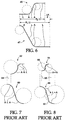
- a profile is illustrated in FIG. 4 , which shows upper profile 41 including sequence LALAL, and lower profile 43 also including sequence LALAL.
- At least one upper root is aligned with at least one corresponding lower root as also shown in FIG. 4 .
- the sum of the length of L1 plus the radius of A1 is equal to or within 20% of the sum of the length of L4 plus the radius of A3, i.e., 0.8 ⁇ (L1+R1)/(L4+R3) ⁇ 1.2. This sum is an approximation of the width of the root, or the distance between adjacent cogs near the base of the cogs.
- the belt will be flexible. It is believed that flexibility is the primary or first consideration to address in designing a long life, high performance VST belt. This is in contrast to teaching in the art that root alignment is not desirable.
- Another advantage of the roots having linear or flat portions is that alignment is easier to achieve during belt manufacture. The wider the root, the more forgiving the manufacturing process will be in terms of root alignment and obtaining the resulting benefits in flexibility.
- the substantial alignment of the upper and lower roots may not or need not necessarily be perfect. It may be sufficient for the linear or flat portions of the upper and lower roots to overlap somewhat in embodiments of the invention. In contrast, very narrow, curved roots must be precisely aligned to realize any benefit in flexibility, leading to manufacturing problems.
- the roots of the lower profile have no flat portion.
- L4 0, or equivalently, the lower cog profile is of the sequence ALAL.
- the alignment of a lower and upper root is still relatively easy to achieve, since the midpoint of the lower root need only be aligned somewhere within the linear or flat portion L1 of the upper root.
- FIG. 5 shows upper profile 45 including sequence LALAL, and lower profile 49 including sequence ALAL. Again, at least one upper root is aligned with at least one corresponding lower root.
- the belt has equal numbers of upper and lower cogs.
- P1 and P2 are equal, when the belt is disposed in rack form.
- a belt wrapped around a sheave has compressed lower dimensions and expanded upper dimensions, so for convenience the belt is described herein in rack form.
- the number of upper cogs, N2 and the number of lower cogs N1 are equal and at least one set of roots are aligned, the entire upper and lower profiles are substantially aligned. Again, this is contrary to much recent teaching in the art.
- root-to-root alignment results in the most flexible belt design possible. Maintaining a flat or linear segment in the upper and lower root makes alignment easier during manufacture.
- the aligned design of the present invention is so much more flexible that the web thickness "W" can be increased somewhat if desired for example to increase transverse strength.
- the belt portion where the roots are aligned may represent the "weak link" of the belt, it is believed that by aligning all the roots, the strength of the weak link can be improved along with the flexibility, resulting in an overall gain in performance.
- the geometry is consistent from cog to cog, so is the deformation and load, and the performance and life of the belt is thus is improved.
- the highest stress regions in conventional designs are associated with the inflexible cog-to-root aligned portions of the belt, which are completely eliminated in the root-to-root aligned embodiment.
- the lower cog profile is of the sequence ALAL, as in the first specific embodiment above.
- L4 0
- the belt still has LALAL-type upper and lower profiles, and at least one upper root is aligned with at least one corresponding lower root, and the sum of the length of L1 plus the radius of A1 is equal to or within 20% of the sum of the length of L4 plus the radius of A3.
- the belt has a greater number of upper cogs than lower cogs.
- P1 > P2 when the belt is disposed in rack form.
- FIG. 6 shows upper profile 46 including sequence LALAL, and lower profile 47 including sequence ALAL. Since only half a pitch is shown, the pitches and the phase shift, " ⁇ P", are indicated as divided by 2.
- the ratio of N2 to N1 is not particularly limited but may preferably be in the range 1.0 to 1.3 or from about 1.1 to about 1.3. Since the number of upper cogs, N2 and the number of lower cogs N1 are not equal, but at least one set of roots are aligned, not the entire upper and lower profiles will be substantially aligned. However, with the upper roots having some linear or flat width, and with N2 not too much larger than N1, there may still be a substantial number of cogs that are substantially aligned. Moreover, the inventive profile shape is improved and therefore, belts of this embodiment are believed to still exhibit enhanced flexibility and performance over other conventional profile designs. It should be understood that the lower cog profile could be of the LALAL type, though the example of FIG. 6 shows it of the ALAL type. This embodiment may encounter lower manufacturing costs as a result of the pitch difference and resulting less-critical alignment of profiles.
- L2 may also be useful to permit L2 to be of zero length, so that the upper profile is of the type LAAL.
- This embodiment may be useful in belts in which it is desired to make the upper cogs relatively short, i.e. h 2 is relatively small.
- V-belts may comprise any suitable material or materials.
- the following material examples are offered by way of example and are not intended to limit the breadth or applicability of the invention.
- Tensile layer 16 may have individual twisted cords of high tensile fibers such as glass, carbon, metal, polyester, nylon, aramid (including PBO), and blends or composites of the foregoing and the like.
- the tensile layer may be woven, fabric, tire cord, or the like as desired.
- the belt body may be of any desired composition, but exemplary materials are rubber compounds based on elastomers such as natural rubber, polychloroprene, polyisoprene, styrenebutadiene rubber, ethylene-alpha-olefin elastomers, nitrile rubber, polyurethane elastomer, various thermoplastic elastomers, and the like. These elastomers may be compounded as known in the art with various fillers, short fiber fillers, plasticizers, oils, process aids, anti-oxidants, anti-ozonants, curatives, coagents, and the like.
- elastomers such as natural rubber, polychloroprene, polyisoprene, styrenebutadiene rubber, ethylene-alpha-olefin elastomers, nitrile rubber, polyurethane elastomer, various thermoplastic elastomers, and the like.
- elastomers may be
- Other reinforcing layers may incorporated into the belt besides the tensile layer, such as other textile layers which may woven, non-woven, knit, or discontinuous fiber layers, oriented or not oriented as known in the art.
- textile layers may be used at any surface of the belt for example to modify the surface properties, strengthen the resistance to crack formation and/or propagation, or the like.
- the invention may be made according to known methods of belt making, including for example, building up the various layers of textiles, elastomers, and tensile members, upright or inverted, on a cylindrical mold or on a mandrel for transfer to a mold.
- the mold may have the cog profile formed therein and/or so-called "matrix" may be used to produce a cog profile.
- matrix may be used to produce a cog profile.
- individual belts After curing or vulcanization to form a double cogged slab, individual belts may be cut and/or ground therefrom with the proper contact surface angle or angles and inverted if necessary.
- the following examples serve to illustrate the advantages of the inventive double-cogged V-belt design over representative other designs found in the art.
- finite element analysis (“FEA") was used to compare various belt designs. In each case the same material properties for the belt body material (a typical elastomer compound) and the tensile layer (a typical aramid tensile cord) were used, so the differences in results would be solely attributable to the profile design differences.
- the FEA modeling included running four models for each belt example to simulate various operational conditions a VST belt sees: a belt bending model, a tension model, an underdrive model, and an overdrive model.
- the bending model started with 1/8 length of belt in a 45° arc as its natural molded shape, then rotated one end an additional 180°, ending in a 225° arc.
- the tension model started with the same 100 mm length of belt in a 90° arc and pulled it straight.
- the overdrive model simulated tensioning the belt between two sheaves by applying a hub load of 1000 N, at sheave diameters representing a high speed ratio, then rotated the driver sheave with 30 Nm of torque on the driven sheave.
- the underdrive model simulated tensioning the belt between two sheaves by applying a hub load of 1000 N, at sheave diameters representing a low speed ratio, then rotated the driver sheave with 30 Nm of torque on the driven sheave.
- Ex. A and Ex. B The dimensions and characteristics of the example belts (Ex. A and Ex. B) are shown in Tables 1-3, along with data for four comparative examples (Comp. Ex. 1-4).
- Table 1 shows the upper cog profile data
- Table 2 shows the lower cog profile data
- Table 3 shows additional general belt geometry data.
- Ex. A is an embodiment of the current invention having upper profile of type LALAL and lower profile of type ALAL, with equal numbers of upper and lower cogs and the profiles aligned root-to-root.
- the comparative examples are based on V-belts for VST applications found in the market currently.
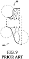
- the cog profiles for Comp. Ex. 1 are shown in FIG. 9 , where upper profile 66 is of type A+LAL, and lower profile 68 is of type ALA.
- the cog profiles for Comp. Ex. 2 are shown in FIG. 7 , where upper profile 62 is of type AAL and lower profile 60 is of type ALA.
- the cog profiles for Comp. Ex. 3 are shown in FIG. 8 , where upper profile 54 is of type A+A and lower profile 56 is of type AL+A.
- the cog profiles for Comp. Ex. 4 are not specifically shown in a separate figure but are of previously illustrated types.
- FIG. 9 where upper profile 66 is of type A+LAL, and lower profile 68 is of type ALA.
- the cog profiles for Comp. Ex. 2 are shown in FIG. 7 , where upper profile 62 is of type AAL and lower profile 60 is of type ALA.
- Table 4 The results of the FEA models are shown in Table 4.
- Table 4 two columns of results are presented for Ex. B. Since Ex. B has more upper cogs than lower cogs, the model predictions for both the aligned portion of the profile and the staggered or non-aligned portion of the profile are presented.
- the column labeled Ex. B-1 provides results for the aligned, root-to-root portion of the belt, while the column labeled Ex. B-1 provides results for the case where a root and a cog are aligned. Since the bending model involves a whole section of belt with both types of alignment included, only one result is presented.
- Results for the tension model are not separately provided since the peak stresses are in the tensile cord layer, and the bending stresses are much less than in the bending model.
- the results are presented as peak strain energy density ("SED") in the region of interest described in the table, namely cog root or cog tip. Also presented is the peak contact friction stress (“CFS”) as described in the table.
- SED peak strain energy density
- CFS peak contact friction stress
- Table 4 presents both absolute values of the above and a relative value, i.e. percent difference ("Diff. (%)" based on the best of the four comparative examples which is indicated with a "B".
- Table 4. Ex. A Ex. B-1 Ex. B-2 Comp. Ex. 1 Comp. Ex. 2 Comp. Ex. 3 Comp.
- the FEA analyses also shows that the peak cog tip strain energy density, namely the SED, increases significantly in the Example belts relative to the comparative examples, by 16 to 21%. This is not necessarily bad, since cog tips are generally not prone to strain or stress-induced cracks. Instead, the increased tip stress may indicate that more of the load is being carried by the cog in accordance with one purpose of having cogs.
- the present invention is shown to provide a double-cogged V-belt, in particular for VST applications, with improved flexibility, reduced tendency to develop root cracks, and improved performance consistency.
Landscapes
- Engineering & Computer Science (AREA)
- General Engineering & Computer Science (AREA)
- Mechanical Engineering (AREA)
- Transmissions By Endless Flexible Members (AREA)
- Devices For Conveying Motion By Means Of Endless Flexible Members (AREA)
Claims (11)
- Courroie en V (10) comportant un certain nombre de dents supérieures (20) et de racines supérieures (22) présentant un pas supérieur et un profil curviligne supérieur, un certain nombre de dents inférieures (18) et de racines inférieures (32) présentant un pas inférieur et un profil curviligne inférieur, et une couche de renfort de résistance à la traction (16) essentiellement à mi-chemin entre les racines supérieures (22) et les racines inférieures (32) ;
le profil supérieur étant symétrique et comprenant des lignes (« L ») et des arcs (« A ») raccordés suivant la séquence L1-A1-L2-A2-L3 du centre de l'une quelconque desdites racines supérieures (22) au centre d'une dent adjacente parmi lesdites dents supérieures (20) ;
le profil inférieur étant symétrique et comprenant des lignes et des arcs raccordés suivant la séquence L4-A3-L5-A4-L6, L4 pouvant présenter une longueur nulle, du centre de l'une quelconque desdites racines inférieures (32) au centre d'une dent adjacente parmi lesdites dents inférieures (18) ; et
la somme de la longueur de L1 plus le rayon de A1 étant égale à la somme de la longueur de L4 plus le rayon de A3 ou différant de celle-ci d'au plus 20 % ; et
les segments d' arc A1, A2, A3 et A4 présentant un rayon et une longueur finis et non égaux à zéro, et les segments de ligne L1, L2, L3, L5 et L6 présentant une longueur finie et non égale à zéro ; et
au moins une desdites racines supérieures (22) étant essentiellement alignée sur au moins une desdites racines inférieures (32),
caractérisée en ce que les racines supérieures (22) comportent une partie plane lorsque la courroie est étendue à plat. - Courroie en V selon la revendication 1, dans laquelle
le nombre de dents supérieures (20) et de dents inférieures (18) est égal, et
les profils supérieur et inférieur sont essentiellement alignés de racine à racine. - Courroie en V selon la revendication 2, dans laquelle la somme de la longueur de L1 plus le rayon de A1 est égale à la somme de la longueur de L4 plus le rayon de A3 ou supérieure à celle-ci d'au plus 20 %.
- Courroie en V selon la revendication 1, dans laquelle le nombre de dents supérieures (20) est supérieur au nombre de dents inférieures (18).
- Courroie en V selon la revendication 4, dans laquelle le nombre de dents supérieures (20) est égal à environ 1,1 à 1,3 fois le nombre de dents inférieures.
- Courroie en V selon la revendication 1, comprenant en outre des surfaces latérales opposées (44) comportant un angle de dépouille disposé à proximité d'une extrémité de dent inférieure (19).
- Courroie en V selon la revendication 1, 3 ou 5, la courroie présentant une largeur au sommet, TW, qui est égale à environ deux fois l'épaisseur totale, To.
- Courroie en V selon la revendication 1, 3 ou 5, dans laquelle l'angle inclus, β1, des flancs (36) d'une dent inférieure (18) se situe dans la plage de 10 à 30 degrés, et l'angle inclus, β2, des flancs (26) d'une dent supérieure (20) se situe dans la plage de 10 à 30 degrés.
- Courroie en V selon la revendication 1, 3 ou 5, dans laquelle lesdites lignes L1 et L2 se raccordent tangentiellement à l'arc A1, et lesdites lignes L4 et L5 se raccordent tangentiellement à l'arc A3.
- Courroie en V selon la revendication 1, 3, 5 ou 9, dans laquelle chaque arc et ligne adjacents des profils supérieur et inférieur se raccordent tangentiellement.
- Courroie en V selon l'une quelconque des revendications 1 à 8, dans laquelle L4 présente une longueur égale à zéro.
Applications Claiming Priority (2)
| Application Number | Priority Date | Filing Date | Title |
|---|---|---|---|
| US12/432,985 US8206251B2 (en) | 2009-04-30 | 2009-04-30 | Double cogged V-belt for variable speed drive |
| PCT/US2010/001106 WO2010126562A1 (fr) | 2009-04-30 | 2010-04-14 | Courroie en v dentée double pour entraînement à vitesse variable |
Publications (2)
| Publication Number | Publication Date |
|---|---|
| EP2425151A1 EP2425151A1 (fr) | 2012-03-07 |
| EP2425151B1 true EP2425151B1 (fr) | 2017-07-26 |
Family
ID=42315310
Family Applications (1)
| Application Number | Title | Priority Date | Filing Date |
|---|---|---|---|
| EP10716131.7A Active EP2425151B1 (fr) | 2009-04-30 | 2010-04-14 | Courroie en v dentée double pour entraînement à vitesse variable |
Country Status (10)
| Country | Link |
|---|---|
| US (3) | US8206251B2 (fr) |
| EP (1) | EP2425151B1 (fr) |
| JP (1) | JP2012525554A (fr) |
| CN (1) | CN102165217B (fr) |
| AU (1) | AU2010242082A1 (fr) |
| BR (1) | BRPI1013337B1 (fr) |
| CA (2) | CA2759329C (fr) |
| MX (1) | MX2011011236A (fr) |
| TW (1) | TW201042185A (fr) |
| WO (1) | WO2010126562A1 (fr) |
Families Citing this family (18)
| Publication number | Priority date | Publication date | Assignee | Title |
|---|---|---|---|---|
| EP2787244B1 (fr) * | 2009-09-24 | 2017-02-01 | Gates Corporation | Chenille en caoutchouc |
| US8512614B2 (en) * | 2011-06-20 | 2013-08-20 | Dayco Ip Holdings, Llc | Modular molding system |
| WO2014017012A1 (fr) * | 2012-07-26 | 2014-01-30 | バンドー化学株式会社 | Courroie de transmission à encoche |
| JP5945562B2 (ja) * | 2013-03-28 | 2016-07-05 | 三ツ星ベルト株式会社 | 伝動用ベルト及びベルト変速装置 |
| JP6371763B2 (ja) * | 2013-05-15 | 2018-08-08 | バンドー化学株式会社 | 歯付ベルトの製造方法 |
| CN105980739B (zh) * | 2014-02-14 | 2018-09-11 | 阪东化学株式会社 | 双齿v型带 |
| CN107735596B (zh) | 2015-05-11 | 2019-10-18 | 盖茨公司 | Cvt皮带 |
| DE102015223800A1 (de) * | 2015-11-30 | 2017-06-01 | Contitech Antriebssysteme Gmbh | Zahnriementrieb |
| CN109196246B (zh) * | 2016-05-20 | 2019-09-24 | 阪东化学株式会社 | 带齿v带及使用了该带齿v带的传动系统 |
| WO2017213103A1 (fr) * | 2016-06-06 | 2017-12-14 | 三ツ星ベルト株式会社 | Courroie crantée et procédé de fabrication s'y rapportant |
| DE102017108425B4 (de) * | 2017-04-20 | 2018-11-29 | Arntz Beteiligungs Gmbh & Co. Kg | Verzahnter Keilriemen |
| JP6660997B2 (ja) * | 2017-12-26 | 2020-03-11 | 三ツ星ベルト株式会社 | 両面歯付ベルト |
| KR102373377B1 (ko) * | 2017-12-26 | 2022-03-11 | 미쓰보 시베루토 가부시키 가이샤 | 양면 톱니 벨트 |
| JP6577157B1 (ja) * | 2018-06-25 | 2019-09-18 | 三ツ星ベルト株式会社 | ラップド結合vベルト |
| PL4004400T3 (pl) * | 2019-07-23 | 2024-01-03 | Gates Corporation | Pas klinowy z środkowym kordem linkowym |
| KR102936009B1 (ko) * | 2021-09-29 | 2026-03-09 | 미쓰보시 베루토 가부시키 가이샤 | 톱니 벨트 및 그 제조 방법 |
| TWI855812B (zh) * | 2022-08-10 | 2024-09-11 | 美商蓋滋公司 | 具有不對稱輪廓的齒之齒形帶 |
| EP4497967A1 (fr) * | 2023-07-28 | 2025-01-29 | ABB E-mobility B.V. | Courroie et système de courroie d'actionneur |
Family Cites Families (42)
| Publication number | Priority date | Publication date | Assignee | Title |
|---|---|---|---|---|
| US1883821A (en) * | 1928-07-30 | 1932-10-18 | Reeves Pulley Co | Driving belt |
| US1890080A (en) * | 1928-08-08 | 1932-12-06 | Abraham L Freedlander | Double cog belt |
| US2062568A (en) * | 1934-07-09 | 1936-12-01 | Dayton Rubber Mfg Co | Cog belt |
| US2121222A (en) * | 1935-03-27 | 1938-06-21 | Dayton Rubber Mfg Co | Belt |
| US2430500A (en) * | 1943-04-12 | 1947-11-11 | Dayton Rubber Company | Wire reinforced double cog belt |
| US2514429A (en) * | 1945-06-27 | 1950-07-11 | Dayton Rubber Company | Double cog belt |
| US2699685A (en) * | 1950-04-29 | 1955-01-18 | Dayton Rubber Company | Double cog belt |
| US2775902A (en) * | 1954-04-08 | 1957-01-01 | Reliance Electric & Eng Co | Belt |
| US3338107A (en) * | 1965-02-15 | 1967-08-29 | Kiekhaefer Corp | Positive drive system |
| US3673883A (en) * | 1971-02-03 | 1972-07-04 | Uniroyal Inc | Toothed power transmission belt and method of manufacturing the same |
| US4228692A (en) * | 1977-08-15 | 1980-10-21 | Dayco Corporation | Endless power transmission belt and method of manufacture |
| US4216679A (en) * | 1978-12-04 | 1980-08-12 | Dayco Corporation | Power transmission belt |
| US4276039A (en) * | 1979-05-03 | 1981-06-30 | Mitsuboshi Belting Ltd. | Adjustless V-belt and method of manufacturing |
| US4410314A (en) * | 1982-02-11 | 1983-10-18 | Dayco Corporation | Endless power transmission V-belt construction and method of making the same |
| US4409047A (en) * | 1982-03-10 | 1983-10-11 | Dayco Corporation | Method of making a top toothed endless power transmission belt construction and a belt construction made by such method |
| JPS61116149A (ja) * | 1984-11-12 | 1986-06-03 | Daido Kogyo Co Ltd | Vベルト |
| JPS61286640A (ja) | 1985-06-14 | 1986-12-17 | Honda Motor Co Ltd | 伝動ベルト |
| IT1186158B (it) * | 1985-12-20 | 1987-11-18 | Pirelli Transmissioni Ind Spa | Cinghia trapezoidale,in particolare per variatori continui di velocita' |
| US4702729A (en) * | 1986-02-10 | 1987-10-27 | Mitsuboshi Belting Ltd. | Timing belt with controlled friction backside ribs |
| JPS62266250A (ja) * | 1986-05-12 | 1987-11-19 | Aisin Seiki Co Ltd | ベルト |
| JPS62199553U (fr) * | 1986-06-09 | 1987-12-18 | ||
| EP0257646B1 (fr) * | 1986-08-28 | 1992-01-29 | Bando Chemical Industries, Ltd. | Courroie trapézoidale à blocs |
| JPS6438349U (fr) * | 1987-09-01 | 1989-03-07 | ||
| CN2079684U (zh) * | 1990-02-27 | 1991-06-26 | 于仲华 | 一种新型三角带 |
| US5273496A (en) * | 1991-06-18 | 1993-12-28 | Dayco Products, Inc. | Belt construction, the combination of the belt construction and a puley and methods of making the same |
| JP2584617Y2 (ja) * | 1991-12-12 | 1998-11-05 | 三ツ星ベルト株式会社 | 高負荷伝動ベルト |
| JP2558070Y2 (ja) * | 1992-11-04 | 1997-12-17 | 三ツ星ベルト株式会社 | Vリブドベルト |
| YU48534B (sh) * | 1992-11-25 | 1998-11-05 | Dragan dr. Milutinović | Zupčasti kaiš kružnog poprečnog preseka |
| IT1265351B1 (it) * | 1993-11-26 | 1996-11-22 | Dayco Pti Spa | Trasmissione a cinghia dentata per il comando di alberi di equilibratura dinamica in motori endotermici |
| DE69505316T2 (de) * | 1994-07-27 | 1999-05-06 | Mitsuboshi Belting Ltd., Kobe, Hyogo | Doppelzeilrippenriemen |
| US6103349A (en) * | 1997-02-18 | 2000-08-15 | Bando Chemical Industries, Ltd. | Belt |
| US6361462B1 (en) * | 1997-10-31 | 2002-03-26 | Mitsuboshi Belting Ltd. | V-ribbed power transmission belt |
| JP2000240732A (ja) * | 1999-02-24 | 2000-09-05 | Bando Chem Ind Ltd | Vリブドベルト及びその製造方法 |
| US6620068B2 (en) * | 2000-04-28 | 2003-09-16 | Mitsuboshi Belting Ltd. | Power transmission belt |
| JP2002031192A (ja) | 2000-07-17 | 2002-01-31 | Mitsuboshi Belting Ltd | ダブルコグドベルト |
| JP2002089631A (ja) | 2000-09-18 | 2002-03-27 | Mitsuboshi Belting Ltd | 動力伝動用ベルト |
| JP2003314619A (ja) * | 2002-04-23 | 2003-11-06 | Bando Chem Ind Ltd | 高負荷伝動ベルト用ゴム組成物及びこのゴム組成物を用いた高負荷伝動ベルト |
| JP2004225804A (ja) | 2003-01-23 | 2004-08-12 | Bando Chem Ind Ltd | ダブルコグドvベルト |
| US20050113199A1 (en) * | 2003-11-26 | 2005-05-26 | Brecoflex Co., L.L.C. | Toothed belt with tooth reinforcements |
| WO2007036960A1 (fr) | 2005-09-27 | 2007-04-05 | Dayco Europe S.R.L. Con Unico Socio | Entrainement par courroie crantee a utiliser dans de l'huile, et courroie crantee correspondante |
| DE102006007509B4 (de) * | 2006-02-16 | 2009-01-22 | Contitech Antriebssysteme Gmbh | Keilrippenriemen mit verbessertem Geräuschverhalten |
| US20100004084A1 (en) * | 2008-07-01 | 2010-01-07 | Xinjian Fan | Variable speed belt |
-
2009
- 2009-04-30 US US12/432,985 patent/US8206251B2/en active Active
-
2010
- 2010-04-14 JP JP2012508463A patent/JP2012525554A/ja active Pending
- 2010-04-14 CA CA2759329A patent/CA2759329C/fr active Active
- 2010-04-14 EP EP10716131.7A patent/EP2425151B1/fr active Active
- 2010-04-14 BR BRPI1013337 patent/BRPI1013337B1/pt active IP Right Grant
- 2010-04-14 WO PCT/US2010/001106 patent/WO2010126562A1/fr not_active Ceased
- 2010-04-14 MX MX2011011236A patent/MX2011011236A/es active IP Right Grant
- 2010-04-14 AU AU2010242082A patent/AU2010242082A1/en not_active Abandoned
- 2010-04-14 CA CA2885846A patent/CA2885846C/fr active Active
- 2010-04-14 CN CN201080002636.XA patent/CN102165217B/zh active Active
- 2010-04-29 TW TW099113653A patent/TW201042185A/zh unknown
-
2012
- 2012-04-16 US US13/448,106 patent/US8333674B2/en active Active
- 2012-10-29 US US13/662,682 patent/US8425357B2/en active Active
Also Published As
| Publication number | Publication date |
|---|---|
| US20120202634A1 (en) | 2012-08-09 |
| WO2010126562A1 (fr) | 2010-11-04 |
| CA2759329C (fr) | 2015-06-30 |
| JP2012525554A (ja) | 2012-10-22 |
| US8206251B2 (en) | 2012-06-26 |
| CA2885846A1 (fr) | 2010-11-04 |
| BRPI1013337B1 (pt) | 2019-12-10 |
| US8425357B2 (en) | 2013-04-23 |
| US20100279808A1 (en) | 2010-11-04 |
| US20130053200A1 (en) | 2013-02-28 |
| CA2885846C (fr) | 2017-05-16 |
| AU2010242082A1 (en) | 2011-10-20 |
| EP2425151A1 (fr) | 2012-03-07 |
| US8333674B2 (en) | 2012-12-18 |
| CN102165217A (zh) | 2011-08-24 |
| CN102165217B (zh) | 2014-11-05 |
| MX2011011236A (es) | 2011-11-29 |
| TW201042185A (en) | 2010-12-01 |
| CA2759329A1 (fr) | 2010-11-04 |
| BRPI1013337A2 (pt) | 2016-10-11 |
Similar Documents
| Publication | Publication Date | Title |
|---|---|---|
| EP2425151B1 (fr) | Courroie en v dentée double pour entraînement à vitesse variable | |
| US20130190120A1 (en) | Double cogged v-belt for variable speed drive | |
| US5123879A (en) | Variable speed transmission device | |
| US4305714A (en) | Heavy duty laminated cogged belt | |
| CN101449082A (zh) | 有齿动力传输带 | |
| KR0163190B1 (ko) | 동력전달 v-벨트 | |
| KR100502763B1 (ko) | 횡방향으로 보강된 무단 변속기용 벨트 | |
| JPS6137489B2 (fr) | ||
| JP2019116968A (ja) | 両面歯付ベルト | |
| US4228692A (en) | Endless power transmission belt and method of manufacture | |
| JPS6342194Y2 (fr) | ||
| US1970509A (en) | Belt | |
| AU2002350210B2 (en) | Low modulus belt | |
| CN111556935B (zh) | 双面附带齿的带 | |
| US11162560B2 (en) | Belt-type transmission | |
| EP4004400B1 (fr) | Courroie en v à ligne de câbles centrale | |
| CA3148251C (fr) | Courroie en v a ligne de cables centrale | |
| JPS6346299B2 (fr) | ||
| JP5017292B2 (ja) | コグドvベルト | |
| JP2005351317A (ja) | 伝動用ベルト | |
| JPH0914356A (ja) | 高負荷伝動用vベルト | |
| JPS62137445A (ja) | Vベルト | |
| HK1051395B (en) | Transverse reinforced cvt belt |
Legal Events
| Date | Code | Title | Description |
|---|---|---|---|
| PUAI | Public reference made under article 153(3) epc to a published international application that has entered the european phase |
Free format text: ORIGINAL CODE: 0009012 |
|
| 17P | Request for examination filed |
Effective date: 20111108 |
|
| AK | Designated contracting states |
Kind code of ref document: A1 Designated state(s): AT BE BG CH CY CZ DE DK EE ES FI FR GB GR HR HU IE IS IT LI LT LU LV MC MK MT NL NO PL PT RO SE SI SK SM TR |
|
| DAX | Request for extension of the european patent (deleted) | ||
| 17Q | First examination report despatched |
Effective date: 20120820 |
|
| GRAP | Despatch of communication of intention to grant a patent |
Free format text: ORIGINAL CODE: EPIDOSNIGR1 |
|
| INTG | Intention to grant announced |
Effective date: 20160120 |
|
| GRAS | Grant fee paid |
Free format text: ORIGINAL CODE: EPIDOSNIGR3 |
|
| RAP1 | Party data changed (applicant data changed or rights of an application transferred) |
Owner name: GATES CORPORATION |
|
| INTC | Intention to grant announced (deleted) | ||
| GRAP | Despatch of communication of intention to grant a patent |
Free format text: ORIGINAL CODE: EPIDOSNIGR1 |
|
| INTG | Intention to grant announced |
Effective date: 20170222 |
|
| GRAA | (expected) grant |
Free format text: ORIGINAL CODE: 0009210 |
|
| AK | Designated contracting states |
Kind code of ref document: B1 Designated state(s): AT BE BG CH CY CZ DE DK EE ES FI FR GB GR HR HU IE IS IT LI LT LU LV MC MK MT NL NO PL PT RO SE SI SK SM TR |
|
| REG | Reference to a national code |
Ref country code: GB Ref legal event code: FG4D |
|
| REG | Reference to a national code |
Ref country code: CH Ref legal event code: EP |
|
| REG | Reference to a national code |
Ref country code: AT Ref legal event code: REF Ref document number: 912662 Country of ref document: AT Kind code of ref document: T Effective date: 20170815 |
|
| REG | Reference to a national code |
Ref country code: IE Ref legal event code: FG4D |
|
| REG | Reference to a national code |
Ref country code: DE Ref legal event code: R096 Ref document number: 602010043871 Country of ref document: DE |
|
| REG | Reference to a national code |
Ref country code: NL Ref legal event code: MP Effective date: 20170726 |
|
| REG | Reference to a national code |
Ref country code: LT Ref legal event code: MG4D |
|
| REG | Reference to a national code |
Ref country code: AT Ref legal event code: MK05 Ref document number: 912662 Country of ref document: AT Kind code of ref document: T Effective date: 20170726 |
|
| PG25 | Lapsed in a contracting state [announced via postgrant information from national office to epo] |
Ref country code: LT Free format text: LAPSE BECAUSE OF FAILURE TO SUBMIT A TRANSLATION OF THE DESCRIPTION OR TO PAY THE FEE WITHIN THE PRESCRIBED TIME-LIMIT Effective date: 20170726 Ref country code: AT Free format text: LAPSE BECAUSE OF FAILURE TO SUBMIT A TRANSLATION OF THE DESCRIPTION OR TO PAY THE FEE WITHIN THE PRESCRIBED TIME-LIMIT Effective date: 20170726 Ref country code: NL Free format text: LAPSE BECAUSE OF FAILURE TO SUBMIT A TRANSLATION OF THE DESCRIPTION OR TO PAY THE FEE WITHIN THE PRESCRIBED TIME-LIMIT Effective date: 20170726 Ref country code: SE Free format text: LAPSE BECAUSE OF FAILURE TO SUBMIT A TRANSLATION OF THE DESCRIPTION OR TO PAY THE FEE WITHIN THE PRESCRIBED TIME-LIMIT Effective date: 20170726 Ref country code: HR Free format text: LAPSE BECAUSE OF FAILURE TO SUBMIT A TRANSLATION OF THE DESCRIPTION OR TO PAY THE FEE WITHIN THE PRESCRIBED TIME-LIMIT Effective date: 20170726 Ref country code: FI Free format text: LAPSE BECAUSE OF FAILURE TO SUBMIT A TRANSLATION OF THE DESCRIPTION OR TO PAY THE FEE WITHIN THE PRESCRIBED TIME-LIMIT Effective date: 20170726 Ref country code: NO Free format text: LAPSE BECAUSE OF FAILURE TO SUBMIT A TRANSLATION OF THE DESCRIPTION OR TO PAY THE FEE WITHIN THE PRESCRIBED TIME-LIMIT Effective date: 20171026 |
|
| PG25 | Lapsed in a contracting state [announced via postgrant information from national office to epo] |
Ref country code: ES Free format text: LAPSE BECAUSE OF FAILURE TO SUBMIT A TRANSLATION OF THE DESCRIPTION OR TO PAY THE FEE WITHIN THE PRESCRIBED TIME-LIMIT Effective date: 20170726 Ref country code: LV Free format text: LAPSE BECAUSE OF FAILURE TO SUBMIT A TRANSLATION OF THE DESCRIPTION OR TO PAY THE FEE WITHIN THE PRESCRIBED TIME-LIMIT Effective date: 20170726 Ref country code: IS Free format text: LAPSE BECAUSE OF FAILURE TO SUBMIT A TRANSLATION OF THE DESCRIPTION OR TO PAY THE FEE WITHIN THE PRESCRIBED TIME-LIMIT Effective date: 20171126 Ref country code: BG Free format text: LAPSE BECAUSE OF FAILURE TO SUBMIT A TRANSLATION OF THE DESCRIPTION OR TO PAY THE FEE WITHIN THE PRESCRIBED TIME-LIMIT Effective date: 20171026 Ref country code: PL Free format text: LAPSE BECAUSE OF FAILURE TO SUBMIT A TRANSLATION OF THE DESCRIPTION OR TO PAY THE FEE WITHIN THE PRESCRIBED TIME-LIMIT Effective date: 20170726 Ref country code: GR Free format text: LAPSE BECAUSE OF FAILURE TO SUBMIT A TRANSLATION OF THE DESCRIPTION OR TO PAY THE FEE WITHIN THE PRESCRIBED TIME-LIMIT Effective date: 20171027 |
|
| REG | Reference to a national code |
Ref country code: FR Ref legal event code: PLFP Year of fee payment: 9 |
|
| PG25 | Lapsed in a contracting state [announced via postgrant information from national office to epo] |
Ref country code: DK Free format text: LAPSE BECAUSE OF FAILURE TO SUBMIT A TRANSLATION OF THE DESCRIPTION OR TO PAY THE FEE WITHIN THE PRESCRIBED TIME-LIMIT Effective date: 20170726 Ref country code: RO Free format text: LAPSE BECAUSE OF FAILURE TO SUBMIT A TRANSLATION OF THE DESCRIPTION OR TO PAY THE FEE WITHIN THE PRESCRIBED TIME-LIMIT Effective date: 20170726 Ref country code: CZ Free format text: LAPSE BECAUSE OF FAILURE TO SUBMIT A TRANSLATION OF THE DESCRIPTION OR TO PAY THE FEE WITHIN THE PRESCRIBED TIME-LIMIT Effective date: 20170726 |
|
| REG | Reference to a national code |
Ref country code: DE Ref legal event code: R097 Ref document number: 602010043871 Country of ref document: DE |
|
| PG25 | Lapsed in a contracting state [announced via postgrant information from national office to epo] |
Ref country code: SK Free format text: LAPSE BECAUSE OF FAILURE TO SUBMIT A TRANSLATION OF THE DESCRIPTION OR TO PAY THE FEE WITHIN THE PRESCRIBED TIME-LIMIT Effective date: 20170726 Ref country code: EE Free format text: LAPSE BECAUSE OF FAILURE TO SUBMIT A TRANSLATION OF THE DESCRIPTION OR TO PAY THE FEE WITHIN THE PRESCRIBED TIME-LIMIT Effective date: 20170726 Ref country code: SM Free format text: LAPSE BECAUSE OF FAILURE TO SUBMIT A TRANSLATION OF THE DESCRIPTION OR TO PAY THE FEE WITHIN THE PRESCRIBED TIME-LIMIT Effective date: 20170726 |
|
| PLBE | No opposition filed within time limit |
Free format text: ORIGINAL CODE: 0009261 |
|
| STAA | Information on the status of an ep patent application or granted ep patent |
Free format text: STATUS: NO OPPOSITION FILED WITHIN TIME LIMIT |
|
| 26N | No opposition filed |
Effective date: 20180430 |
|
| PG25 | Lapsed in a contracting state [announced via postgrant information from national office to epo] |
Ref country code: SI Free format text: LAPSE BECAUSE OF FAILURE TO SUBMIT A TRANSLATION OF THE DESCRIPTION OR TO PAY THE FEE WITHIN THE PRESCRIBED TIME-LIMIT Effective date: 20170726 |
|
| PG25 | Lapsed in a contracting state [announced via postgrant information from national office to epo] |
Ref country code: MC Free format text: LAPSE BECAUSE OF FAILURE TO SUBMIT A TRANSLATION OF THE DESCRIPTION OR TO PAY THE FEE WITHIN THE PRESCRIBED TIME-LIMIT Effective date: 20170726 |
|
| REG | Reference to a national code |
Ref country code: CH Ref legal event code: PL |
|
| REG | Reference to a national code |
Ref country code: BE Ref legal event code: MM Effective date: 20180430 |
|
| REG | Reference to a national code |
Ref country code: IE Ref legal event code: MM4A |
|
| PG25 | Lapsed in a contracting state [announced via postgrant information from national office to epo] |
Ref country code: LU Free format text: LAPSE BECAUSE OF NON-PAYMENT OF DUE FEES Effective date: 20180414 |
|
| PG25 | Lapsed in a contracting state [announced via postgrant information from national office to epo] |
Ref country code: CH Free format text: LAPSE BECAUSE OF NON-PAYMENT OF DUE FEES Effective date: 20180430 Ref country code: LI Free format text: LAPSE BECAUSE OF NON-PAYMENT OF DUE FEES Effective date: 20180430 Ref country code: BE Free format text: LAPSE BECAUSE OF NON-PAYMENT OF DUE FEES Effective date: 20180430 |
|
| PG25 | Lapsed in a contracting state [announced via postgrant information from national office to epo] |
Ref country code: IE Free format text: LAPSE BECAUSE OF NON-PAYMENT OF DUE FEES Effective date: 20180414 |
|
| PG25 | Lapsed in a contracting state [announced via postgrant information from national office to epo] |
Ref country code: MT Free format text: LAPSE BECAUSE OF NON-PAYMENT OF DUE FEES Effective date: 20180414 |
|
| PG25 | Lapsed in a contracting state [announced via postgrant information from national office to epo] |
Ref country code: TR Free format text: LAPSE BECAUSE OF FAILURE TO SUBMIT A TRANSLATION OF THE DESCRIPTION OR TO PAY THE FEE WITHIN THE PRESCRIBED TIME-LIMIT Effective date: 20170726 |
|
| PG25 | Lapsed in a contracting state [announced via postgrant information from national office to epo] |
Ref country code: HU Free format text: LAPSE BECAUSE OF FAILURE TO SUBMIT A TRANSLATION OF THE DESCRIPTION OR TO PAY THE FEE WITHIN THE PRESCRIBED TIME-LIMIT; INVALID AB INITIO Effective date: 20100414 Ref country code: PT Free format text: LAPSE BECAUSE OF FAILURE TO SUBMIT A TRANSLATION OF THE DESCRIPTION OR TO PAY THE FEE WITHIN THE PRESCRIBED TIME-LIMIT Effective date: 20170726 |
|
| PG25 | Lapsed in a contracting state [announced via postgrant information from national office to epo] |
Ref country code: MK Free format text: LAPSE BECAUSE OF NON-PAYMENT OF DUE FEES Effective date: 20170726 Ref country code: CY Free format text: LAPSE BECAUSE OF FAILURE TO SUBMIT A TRANSLATION OF THE DESCRIPTION OR TO PAY THE FEE WITHIN THE PRESCRIBED TIME-LIMIT Effective date: 20170726 |
|
| PGFP | Annual fee paid to national office [announced via postgrant information from national office to epo] |
Ref country code: DE Payment date: 20250319 Year of fee payment: 16 |
|
| PGFP | Annual fee paid to national office [announced via postgrant information from national office to epo] |
Ref country code: GB Payment date: 20260319 Year of fee payment: 17 |
|
| PGFP | Annual fee paid to national office [announced via postgrant information from national office to epo] |
Ref country code: IT Payment date: 20260319 Year of fee payment: 17 |
|
| PGFP | Annual fee paid to national office [announced via postgrant information from national office to epo] |
Ref country code: FR Payment date: 20260320 Year of fee payment: 17 |