EP2423112A1 - Method and device for manufacturing packaging for cigarettes - Google Patents
Method and device for manufacturing packaging for cigarettes Download PDFInfo
- Publication number
- EP2423112A1 EP2423112A1 EP11005128A EP11005128A EP2423112A1 EP 2423112 A1 EP2423112 A1 EP 2423112A1 EP 11005128 A EP11005128 A EP 11005128A EP 11005128 A EP11005128 A EP 11005128A EP 2423112 A1 EP2423112 A1 EP 2423112A1
- Authority
- EP
- European Patent Office
- Prior art keywords
- glue
- units
- cleaning
- folding
- transport path
- Prior art date
- Legal status (The legal status is an assumption and is not a legal conclusion. Google has not performed a legal analysis and makes no representation as to the accuracy of the status listed.)
- Granted
Links
- 235000019504 cigarettes Nutrition 0.000 title claims abstract description 20
- 238000004519 manufacturing process Methods 0.000 title claims abstract description 4
- 238000004806 packaging method and process Methods 0.000 title claims description 5
- 238000000034 method Methods 0.000 title abstract description 6
- 239000003292 glue Substances 0.000 claims abstract description 238
- 238000004140 cleaning Methods 0.000 claims abstract description 79
- 239000011111 cardboard Substances 0.000 claims abstract description 4
- 239000004831 Hot glue Substances 0.000 claims description 34
- 210000000056 organ Anatomy 0.000 claims description 18
- 239000012459 cleaning agent Substances 0.000 claims description 5
- 238000009413 insulation Methods 0.000 claims description 5
- 238000009826 distribution Methods 0.000 claims description 4
- 239000005022 packaging material Substances 0.000 claims description 3
- 238000009429 electrical wiring Methods 0.000 claims description 2
- 230000003750 conditioning effect Effects 0.000 claims 1
- 230000000712 assembly Effects 0.000 abstract 4
- 238000000429 assembly Methods 0.000 abstract 4
- 239000000463 material Substances 0.000 abstract 1
- 238000012856 packing Methods 0.000 abstract 1
- 239000012943 hotmelt Substances 0.000 description 3
- 239000003795 chemical substances by application Substances 0.000 description 2
- 238000004026 adhesive bonding Methods 0.000 description 1
- 238000011109 contamination Methods 0.000 description 1
- 238000001816 cooling Methods 0.000 description 1
- 230000001419 dependent effect Effects 0.000 description 1
- 239000003599 detergent Substances 0.000 description 1
- 239000006260 foam Substances 0.000 description 1
- 238000010438 heat treatment Methods 0.000 description 1
- 230000001681 protective effect Effects 0.000 description 1
- 238000004513 sizing Methods 0.000 description 1
- 238000011144 upstream manufacturing Methods 0.000 description 1
- XLYOFNOQVPJJNP-UHFFFAOYSA-N water Substances O XLYOFNOQVPJJNP-UHFFFAOYSA-N 0.000 description 1
Images


Classifications
-
- B—PERFORMING OPERATIONS; TRANSPORTING
- B65—CONVEYING; PACKING; STORING; HANDLING THIN OR FILAMENTARY MATERIAL
- B65B—MACHINES, APPARATUS OR DEVICES FOR, OR METHODS OF, PACKAGING ARTICLES OR MATERIALS; UNPACKING
- B65B19/00—Packaging rod-shaped or tubular articles susceptible to damage by abrasion or pressure, e.g. cigarettes, cigars, macaroni, spaghetti, drinking straws or welding electrodes
- B65B19/02—Packaging cigarettes
- B65B19/22—Wrapping the cigarettes; Packaging the cigarettes in containers formed by folding wrapping material around formers
- B65B19/223—Wrapping the cigarettes; Packaging the cigarettes in containers formed by folding wrapping material around formers in a curved path; in a combination of straight and curved paths, e.g. on rotary tables or other endless conveyors
-
- B—PERFORMING OPERATIONS; TRANSPORTING
- B05—SPRAYING OR ATOMISING IN GENERAL; APPLYING FLUENT MATERIALS TO SURFACES, IN GENERAL
- B05B—SPRAYING APPARATUS; ATOMISING APPARATUS; NOZZLES
- B05B15/00—Details of spraying plant or spraying apparatus not otherwise provided for; Accessories
- B05B15/50—Arrangements for cleaning; Arrangements for preventing deposits, drying-out or blockage; Arrangements for detecting improper discharge caused by the presence of foreign matter
- B05B15/52—Arrangements for cleaning; Arrangements for preventing deposits, drying-out or blockage; Arrangements for detecting improper discharge caused by the presence of foreign matter for removal of clogging particles
-
- B—PERFORMING OPERATIONS; TRANSPORTING
- B65—CONVEYING; PACKING; STORING; HANDLING THIN OR FILAMENTARY MATERIAL
- B65B—MACHINES, APPARATUS OR DEVICES FOR, OR METHODS OF, PACKAGING ARTICLES OR MATERIALS; UNPACKING
- B65B51/00—Devices for, or methods of, sealing or securing package folds or closures; Devices for gathering or twisting wrappers, or necks of bags
- B65B51/02—Applying adhesives or sealing liquids
- B65B51/023—Applying adhesives or sealing liquids using applicator nozzles
Definitions
- the invention relates to a device for producing packages for cigarettes, in particular of the folding box type, with a folding device, in particular a folding turret, for folding blanks of packaging material, in particular thin cardboard, and with a subsequent to the folding conveyor transport path, in particular packaging web, for a large extent finished packs, wherein in the transport path a glue application station with glue units, in particular glue nozzles, is provided for applying glue to folding flaps of the blank, according to the preamble of claim 1. Furthermore, the invention relates to a corresponding method according to the preamble of claim 15.
- the invention is based on the object of further developing devices and methods of the type mentioned, in particular with regard to the simultaneous application of cold glue and hot glue on folding flaps of a cigarette pack.
- a device has the features of claim 1. It is therefore provided that the glue units are arranged in a glue application position on both sides of the transport path at the level of the folding flaps to be glued and are movable together in at least one cleaning position for cleaning the glue units.
- the cleaning of the glue units prevents the problems mentioned above and leads to a proper glue pattern.
- a first cleaning position Leimportionen against a arranged between the glue aggregates common collecting organ can be issued. Furthermore, it can additionally be provided that in a second cleaning position, in particular the glue units for applying cold glue can be cleaned by abutment against a common cleaning member.
- glue units are arranged in the or each cleaning position in a plane below the preferably horizontally oriented transport path.
- Another special feature may be that on the one hand glue units for applying cold glue and on the other hand glue units for applying hot glue are arranged successively along the transport path, the respective glue units are arranged opposite each other on both sides of the transport path for applying corresponding glue on preferably upright folding tabs in the range of Narrow sides of the package and that the glue units for applying cold glue on the one hand and the glue units for applying hot glue on the other hand are each movable together in at least one cleaning position.
- the glue units for applying cold glue on the one hand and the glue units for applying hot glue on the other hand can be moved independently by separate drives between the glue application position and the or each cleaning position.
- the glue units for applying cold glue on the one hand and the glue units for applying hot glue on the other hand are preferably movable in a substantially vertical direction.
- Another special feature may consist in that in each case a collecting device for hot glue and cold glue is provided, wherein the collecting organs each extend upright between the opposite glue units, which are preferably arranged for dispensing glue portions in a substantially horizontal direction, preferably below the respective Collecting member is provided in each case a collecting means, in particular a glue trough, for given by the respective collecting organ glue, wherein the collecting means are separately handled and in particular emptied.
- the collecting device for hot glue is heated to avoid glue deposits and to forward the glue to an associated collecting means.
- Another special feature may consist in that the glue units for applying cold glue in the second cleaning position abut against stationary rotatable cleaning rollers, wherein the cleaning rollers are driven by a common drive and each rest on another pair of lower cleaning rollers, which are wettable with a detergent , in particular by immersing the lower one Cleaning rollers in a container the cleaning agent, wherein the container is mounted laterally removable together with the lower cleaning rollers for cleaning purposes.
- the glue units, the collecting organs and the collecting means are connected to a jointly movable unit, which is mounted without retracting the relative position of said organs together from the device.
- the jointly movable unit may have an electrical wiring box movable together with the unit, such that the members of the unit are connected to the junction box.
- a device for aligning side tabs in the region of a lid of the pack is arranged, in particular an aligner shaft, wherein the glue units in Connected to the device are arranged such that the folding flaps of the blank can be glued immediately after the alignment of the lid of the pack.
- a method according to the invention has the features of claim 15. It is therefore envisaged that the glue units are moved together from a glue application position on both sides of the transport path at the level of the folding flaps to be glued into at least one cleaning position for cleaning the glue units.
- This type of package consists of box part 11 and lid 12.
- the box part 11 has a box front wall 13 and a box rear wall 14, which are connected to each other via a bottom wall 15.
- the lid 12 includes a lid front wall 16, a lid rear wall 17, and a lid end wall 18 therebetween.
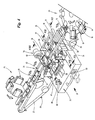
- the schematic in Fig. 4 illustrated device as part of a packaging machine for producing cigarette packs of the type folding box consists of a folding turret 23, a subsequent (straight) transport path 24 and a transfer turret 25th
- Contents of the pack 10 is a cigarette block 26 in the form of a cigarette group wrapped in an inner blank.
- the cigarette block 26 is enveloped in the area of the folding turret 23 in a blank for the pack 10.
- the largely finished pack 10 is ejected in the radial direction from pockets of the folding turret 23 and transferred to the transport path 24.
- the packs 10 are transported at a distance from each other by an endless conveyor.
- This is designed as a belt conveyor 27, as a toothed belt.
- On the free side drivers 28 are arranged, each detecting and transporting a pack 10 in the region of the rear bottom wall 15.
- the packs 10 lie with their longitudinal extent pointing in the conveying direction on the belt conveyor 27 and / or on a longitudinal direction of the transport path 24 extending guide profile 29.
- guide and support members are provided in the region of the transport path.
- the laterally directed folding tabs namely box side tabs 19 and lid side tabs 21, rest on legs 30 of the guide profile 29.
- guide rails 31 extending in the conveying direction are arranged on the upper side of the packs 10 and hold the packs 10 in the exact position on or in the conveying track 24.
- the packages 10 are preferably transported continuously along the transport path 24.
- folding flaps are provided with glue, in the present case, the upright inner box side flaps 20 and lid side flaps 22.
- the package 10 is ready folded, namely by folding the box side flaps 19 and lid side tabs 21 until it rests against the associated side tabs 20, 22.
- the now finished package 10 is transferred to the forming unit, namely to the transfer turret 25th
- the device is adapted to transfer two different types of glue to the package 10, namely cold glue on the one hand and hot melt (hotmelt) on the other.
- a first glue station 32 is used to transfer hot glue.
- a second sizing station 33 following in the conveying direction is set up for the transfer of cold glue.
- the first glue station 32 has two glue units 34, 35 on both sides of the transport path 24.
- the glue units 34, 35 have glue nozzles 36 for transferring glue dots 37 onto the package 10.
- a special feature is that the glue portions are dispensed in a horizontal direction and transferred to an upright folding flap 20, 22.
- the second glue station 33 in the present case also consists of two glue units 40, 41 on both sides of the transport path 24 for the transfer of individual glue spots 42 of another type of glue, namely cold glue.
- the glue units 40, 4 of the second glue station 33 are designed or arranged such that two superimposed rows of dots 38, 39 of the glue are produced. As compared to the FIGS. 2 and 3 it can be seen that in packs 10 with a smaller number of layers of cigarettes in the cigarette block 26, only one row of dots 38 is attached by appropriate control of the glue units 40, 41.
- the glue points 42 of the first glue station 32 are mounted in a lower plane relative to the transport path 24.
- the glue spots 42 of hotmelt are applied between glue points 37 of the point row 38, ie adjacent to a free edge for connection to the side flaps 20, 22 certain outer side lobes 19,21.
- the glue points 37, 42 can during the stoppage of the packs 10 by the appropriately trained glue units 34, 35; 40, 41 are transmitted. in the In the present case, the glue spots 37, 42, however, by the glue units 34, 35; 40, 41 transferred during the movement of the packs 10 on the side lobes 20, 22.
- the packs 10 reach the region of a folding station with folding members, which in the present case are designed as folding switches 43 on both sides of the conveying track 24.
- folding members which in the present case are designed as folding switches 43 on both sides of the conveying track 24.
- the shaped, rail-like Faltrise 43 cause the side tabs 19, 21 are folded down during transport to the complete abutment against the side flaps 20, 22.
- the finished package 10 is conveyed away.
- a special feature of the device is that the glue units 34, 35 on the one hand and glue units 40, 41 on the other hand can each be moved in pairs in one or more cleaning positions.
- the glue units 34, 35 of the glue station 32 for the application of hot glue can be moved in the vertical direction, or substantially transversely to the transport path 24, namely in a cleaning position below the transport path 24.
- This cleaning position is in Fig. 7 shown.
- Fig. 6 a glue application position of the glue station 32.
- dashed lines is in Fig. 6 the cleaning position according to Fig. 7 indicated.
- the glue units 34, 35 are mounted in the present case on a common, not shown in detail, support means 44, which is movable in the present case by means of a pneumatic cylinder 45 as a drive in the vertical direction.
- support means 44 which is movable in the present case by means of a pneumatic cylinder 45 as a drive in the vertical direction.
- pneumatic cylinder 45 As a drive in the vertical direction.
- other drives come into question for this purpose.
- the two glue units 34, 35 are supplied via hot glue lines 46 with hot glue.
- both the hot glue lines 46 are insulated or heated and the hot glue connections 47 of the hot glue lines 46 on the glue units 34, 35.
- a stationary collecting element 49 is arranged between the glue units 34, 35 and the nozzle tips 48.
- the collecting member 49 serves to receive glue portions of hot glue, which are delivered in the cleaning position of the two glue units 34, 35 in order to prevent clogging of the glue units 34, 35.
- the collecting element 49 is arranged at a distance from the mutual nozzle tips 49 and prevents the mutual glue units 34, 35 from polluting each other with glue portions.
- the catcher 49 has in the present case a wall-like shape with a substantially vertical extent. In cross section ( Fig. 7 ) side walls of the collecting organ 49 also converge downwardly converging. In this way, the glue dispensed by two glue units 34, 35 run on both sides of the collecting organ 49 down and drip from there into a collecting means 50, in particular in the form of a hot glue drip tray.
- the hot glue collecting tray as collecting means 50 is mounted on guides 51, so that they can be pulled laterally out of the device to empty the tub and clean.
- the glue units 34, 35 need not necessarily be moved in the vertical direction between the glue application position and the cleaning position. It is also conceivable, for example, a pivoting of the two glue units 34, 35, so that the glue portions can be delivered against a common collecting organ 49.
- the two glue units 34, 35 with respect to their relative position relative to the packs 10 and the transport path 24 are adjustable.
- the glue units 34, 35 are adjustable in the horizontal direction. This is done via adjusting screws 52. In this way, the lateral distance 53 of the glue units 34, 35 with respect to the packs 10 is adjustable. Furthermore, adjusting screws 54 for adjusting the height of the glue units 34, 35 are provided.
- the glue units 34, 35 are provided with an insulation 55, which also includes the area of the nozzle tips 48.
- the nozzle tips 48 are elongated over conventional nozzle tips, i. these protrude further out of the glue unit than usual. In this way, it is possible to arrange the insulation 55 also in the area surrounding the nozzle tips 48.
- the catching element 49 In order to prevent the glue portions emitted by the glue units 34, 35 from settling on the catching element 49, provision can furthermore be made for the catching element 49 to be designed to be heatable.
- a central heating device 56 may be provided in the collecting element 49, which heats the walls of the collecting element 49 and thus prevents cooling and settling of hot glue in this area.
- the two glue units 40, 41 can also be moved from an (upper) glue application position into a (middle) first cleaning position.
- This first cleaning position is in Fig. 8 shown.
- the glue units 40, 41 are below the transport path 24.
- a collecting member 57 is provided for Kaltleimportionen that like the collecting organ 49 is positioned for the H mitigateleimportionen between the glue units 40, 41 and from the glue units 40, 41 delivered Leimportionen fields.
- a collecting means 58 is provided for cold glue, for example in the form of a cold glue collecting tray, which can be pulled laterally out of the device in order to empty and clean them.
- a special feature of this drip tray is that it has a C-shaped floor plan and is angled twice starting from the area between the glue units 40, 41.
- the bottom of the collecting means 58 is formed inclined over the course, so that the collecting means 58 in the area between the glue units 40, 41 only has a small height, but then increases continuously over the course. In this way, the collecting means 58, despite the small space in the area between the glue units 40, 41 overall a sufficient volume.
- the glue units 40, 41 are also still in a further (lower) second cleaning position movable, which is in the present case below the first cleaning position.
- This (lowest) cleaning position is in Fig. 8 indicated by dashed lines.
- the cleaning rollers 59 is associated with a pair of other cleaning rollers 61, which are also rotatably mounted below the first cleaning rollers 59 and abut the cleaning rollers 59 and thus indirectly driven by the drive 60 with.
- the cleaning rollers 61 are immersed in a container 62 with a cleaning agent 63, in particular water, for cleaning the glue units 40, 10 or the cleaning rollers 59.
- the container 62 with the cleaning agent 63 is mounted laterally removable from the device.
- guide pins 64 are provided on which the container 62 is displaceably mounted in the longitudinal direction.
- the height adjustment of the glue units 40, 41 success via a two pneumatic cylinders 65, 66 accordingly Fig. 9 ,
- the pneumatic cylinders 65, 66 are each covered by protective devices 67, 68, so that they can be avoided by glue.
- the glue units 40, 41 are mounted on a common support means to simultaneously move both organs together between the positions can.
- the glue units 40, 41 do not necessarily have to be moved in the vertical direction. It is also conceivable to pivot the glue units 40, 41, as already described for the glue units 34, 35.
- each glue unit 40, 41 for cold glue on two glue nozzles 69 which are arranged offset in the conveying direction of the packs 10 at a distance from each other and in height.
- the offset 70 of the nozzles, the two rows of points 38, 39 are generated.
- the unit comprises in particular the glue units 34, 35; 40, 41 the drives for moving the glue units 34, 35; 40, 41 between the stations and the collecting device 49, 57 and collecting means 50, 58 and the container 62 with the cleaning rollers 59, 61st
- the drawer 71 is longitudinally displaceably mounted with double-sided rails 72 between pairs of sliding shoes 73, so that the drawer with the entire unit can be pulled laterally out of the device without the relative position of the individual members being changed relative to one another.
- the drawer is supported by strips 76 on a machine bed 77. Independently of this, the collecting means 50, 58 and the container 62 can be pulled out laterally relative to the unit.
- a detent 79 is provided which works together with the longitudinal guide of the drawer 71.
- the drawer 71 can be locked accordingly in the retracted position, for example by a corresponding locking member.
- the power supply is bundled to a distribution box 74 laterally in or on the drawer 71. From the distribution box 74 from the individual units are supplied via power lines 75 with power.
- a device for aligning folding flaps of the package 10 in the region of the lid 12 is arranged in the region of the glue units 40, 41, namely an aligner shaft 78.
- the aligning shaft 78 is arranged upstream of the glue units 40, 41, so that the cold glue is applied to the aligned folding flaps can.
- the operation of the aligner shaft 78 results from DE 100 31 319 A1 ,
- the device described so far in its essential parts functions as follows: In the event of an interruption of the operation of the device, the glue units 34, 35; 40 41 moved to the cleaning position. For the glue units 34, 35 for the application of hot glue, this means that they are moved into the cleaning position for the delivery of glue portions below the transport path 24. The glue units 40, 41 are also moved to this position. Furthermore, the glue units 40, 41 can still be moved into the second cleaning position in contact with the cleaning rollers 59. This is done in accordance with a corresponding programming of a machine control for the device. The selection of the cleaning position to be approached can be made dependent in particular on the duration of the interruption.
Abstract
Description
Die Erfindung betrifft eine Vorrichtung zum Herstellen von Packungen für Zigaretten, insbesondere des Typs Klappschachtel, mit einer Falteinrichtung, insbesondere einem Faltrevolver, zum Falten von Zuschnitten aus Verpackungsmaterial, insbesondere dünnem Karton, und mit einer an die Falteinrichtung anschließenden Transportbahn, insbesondere Packungsbahn, für weitgehend fertiggestellte Packungen, wobei im Bereich der Transportbahn eine Leimauftragsstation mit Leimaggregaten, insbesondere Leimdüsen, zum Aufbringen von Leim auf Faltlappen des Zuschnitts vorgesehen ist, gemäß dem Oberbegriff des Anspruchs 1. Weiterhin betrifft die Erfindung ein entsprechendes Verfahren gemäß dem Oberbegriff des Anspruchs 15.The invention relates to a device for producing packages for cigarettes, in particular of the folding box type, with a folding device, in particular a folding turret, for folding blanks of packaging material, in particular thin cardboard, and with a subsequent to the folding conveyor transport path, in particular packaging web, for a large extent finished packs, wherein in the transport path a glue application station with glue units, in particular glue nozzles, is provided for applying glue to folding flaps of the blank, according to the preamble of claim 1. Furthermore, the invention relates to a corresponding method according to the preamble of
Der Auftrag von Leim auf Zuschnitte für Zigarettenpackungen erfolgt in der Praxis in der Regel mit Hilfe von Leimrädern oder Leimdüsen. Ein grundsätzliches Problem stellt die Verschmutzung der entsprechenden Leimaggregate im laufenden Betrieb dar. Dies kann dazu führen, dass der Auftrag gestört wird, was zu einem unsauberen Leimbild führen kann.The application of glue on blanks for cigarette packs is done in practice usually with the help of glue wheels or glue nozzles. A fundamental problem is the contamination of the corresponding glue units during operation. This can lead to the order being disturbed, which can lead to an unclean glue pattern.
Hiervon ausgehend liegt der Erfindung die Aufgabe zu Grunde Vorrichtungen und Verfahren der eingangs genannten Art weiterzuentwickeln, insbesondere im Hinblick auf den gleichzeitigen Auftrag von Kaltleim und Heißleim auf Faltlappen einer Zigarettenpackung.On this basis, the invention is based on the object of further developing devices and methods of the type mentioned, in particular with regard to the simultaneous application of cold glue and hot glue on folding flaps of a cigarette pack.
Zur Lösung dieser Aufgabe weist eine erfindungsgemäße Vorrichtung die Merkmale des Anspruchs 1 auf. Es ist demnach vorgesehen, dass die Leimaggregate in einer Leimauftragsstellung auf beiden Seiten der Transportbahn auf Höhe der zu beleimenden Faltlappen angeordnet sind und zusammen in wenigstens eine Reinigungsstellung bewegbar sind zum Reinigen der Leimaggregate.To achieve this object, a device according to the invention has the features of claim 1. It is therefore provided that the glue units are arranged in a glue application position on both sides of the transport path at the level of the folding flaps to be glued and are movable together in at least one cleaning position for cleaning the glue units.
Die Reinigung der Leimaggregate verhindert die eingangs genannten Probleme und führt zu einem ordnungsgemäßen Leimbild.The cleaning of the glue units prevents the problems mentioned above and leads to a proper glue pattern.
Gemäß einer bevorzugten Weiterbildung ist vorgesehen, dass in einer ersten Reinigungsstellung Leimportionen gegen ein zwischen den Leimaggregaten angeordnetes gemeinsames Auffangorgan abgebbar sind. Weiterhin kann zusätzlich vorgesehen sein, dass in einer zweiten Reinigungsstellung insbesondere die Leimaggregate zum Auftragen von Kaltleim durch Anlage an einem gemeinsamen Reinigungsorgan reinigbar sind.According to a preferred embodiment, it is provided that in a first cleaning position Leimportionen against a arranged between the glue aggregates common collecting organ can be issued. Furthermore, it can additionally be provided that in a second cleaning position, in particular the glue units for applying cold glue can be cleaned by abutment against a common cleaning member.
In einer bevorzugten Ausführungsform der Erfindung ist vorgesehen, dass Leimaggregate in der oder jeder Reinigungsstellung in einer Ebene unterhalb der vorzugsweise horizontal gerichteten Transportbahn angeordnet sind.In a preferred embodiment of the invention it is provided that glue units are arranged in the or each cleaning position in a plane below the preferably horizontally oriented transport path.
Eine weitere Besonderheit kann darin bestehen, dass einerseits Leimaggregate zum Aufbringen von Kaltleim und andererseits Leimaggregate zum Aufbringen von Heißleim aufeinander folgend entlang der Transportbahn angeordnet sind, wobei die jeweiligen Leimaggregate gegenüberliegend beiderseits der Transportbahn angeordnet sind zum Aufbringen entsprechenden Leims an vorzugsweise aufrechten Faltlappen im Bereich von Schmalseiten der Packung und dass die Leimaggregate zum Aufbringen von Kaltleim einerseits und die Leimaggregate zum Aufbringen von Heißleim andererseits jeweils gemeinsam in wenigstens eine Reinigungsstellung bewegbar sind.Another special feature may be that on the one hand glue units for applying cold glue and on the other hand glue units for applying hot glue are arranged successively along the transport path, the respective glue units are arranged opposite each other on both sides of the transport path for applying corresponding glue on preferably upright folding tabs in the range of Narrow sides of the package and that the glue units for applying cold glue on the one hand and the glue units for applying hot glue on the other hand are each movable together in at least one cleaning position.
Vorzugsweise ist dies derart umgesetzt, dass die Leimaggregate zum Aufbringen von Kaltleim an einer gemeinsamen ersten Trageinrichtung angebracht sind und mit dieser zwischen der Leimauftragsstellung zum Auftragen von Leim auf die Zuschnitte, einer ersten Reinigungsstellung zum Abgeben von Leimportionen auf das Auffangorgan und einer zweiten Reinigungsstellung zum Reinigen der Leimaggregate bewegbar sind und dass die Leimaggregate zum Aufbringen von Heißleim an einer gemeinsamen zweiten Trageinrichtung angebracht sind und mit dieser zwischen einer Leimauftragsstellung zum Auftragen von Leim auf die Zuschnitte und einer Reinigungsstellung zum Abgeben von Leimportionen auf das Auffangorgan bewegbar sind.This is preferably implemented in such a way that the glue units for applying cold glue are attached to a common first carrying device and with this between the glue application position for applying glue to the blanks, a the first cleaning position for dispensing glue portions on the collecting device and a second cleaning position for cleaning the glue units are movable and that the glue units are applied for applying hot glue to a common second support means and with this between a glue application position for applying glue to the blanks and a cleaning position for dispensing Leimportionen on the collecting organ are movable.
Die Leimaggregate zum Aufbringen von Kaltleim einerseits und die Leimaggregate zum Aufbringen von Heißleim andererseits können durch separate Antriebe unabhängig voneinander zwischen der Leimauftragsstellung und der oder jeder Reinigungsstellung bewegbar sein.The glue units for applying cold glue on the one hand and the glue units for applying hot glue on the other hand can be moved independently by separate drives between the glue application position and the or each cleaning position.
Entsprechend der Ausrichtung der Transportbahn sind die Leimaggregate zum Aufbringen von Kaltleim einerseits und die Leimaggregate zum Aufbringen von Heißleim andererseits vorzugsweise in im Wesentlichen vertikaler Richtung bewegbar.According to the orientation of the transport path, the glue units for applying cold glue on the one hand and the glue units for applying hot glue on the other hand are preferably movable in a substantially vertical direction.
Eine weitere Besonderheit kann darin bestehen, dass jeweils ein Auffangorgan für Heißleim und für Kaltleim vorgesehen ist, wobei sich die Auffangorgane jeweils aufrecht zwischen den gegenüberliegenden Leimaggregaten erstrecken, die zur Abgabe von Leimportionen vorzugsweise in im wesentlichen horizontaler Richtung angeordnet sind, wobei vorzugsweise unterhalb des jeweiligen Auffangorgans jeweils ein Auffangmittel, insbesondere eine Leimwanne, für von dem jeweiligen Auffangorgan abgegebenen Leim vorgesehen ist, wobei die Auffangmittel separat handhabbar und insbesondere entleerbar sind.Another special feature may consist in that in each case a collecting device for hot glue and cold glue is provided, wherein the collecting organs each extend upright between the opposite glue units, which are preferably arranged for dispensing glue portions in a substantially horizontal direction, preferably below the respective Collecting member is provided in each case a collecting means, in particular a glue trough, for given by the respective collecting organ glue, wherein the collecting means are separately handled and in particular emptied.
Vorzugsweise ist das Auffangorgan für Heißleim beheizt zur Vermeidung von Leimablagerungen und zur Weiterleitung des Leims an ein zugeordnetes Auffangmittel.Preferably, the collecting device for hot glue is heated to avoid glue deposits and to forward the glue to an associated collecting means.
Eine weitere Besonderheit kann darin bestehen, dass die Leimaggregate zum Aufbringen von Kaltleim in der zweiten Reinigungsstellung an ortsfest drehbaren Reinigungsrollen anliegen, wobei die Reinigungsrollen durch einen gemeinsamen Antrieb antreibbar sind und jeweils an einem weiteren Paar von unteren Reinigungsrollen anliegen, die mit einem Reinigungsmittel benetzbar sind, insbesondere durch Eintauchen der unteren Reinigungsrollen in einen Behälter dem Reinigungsmittel, wobei der Behälter zusammen mit den unteren Reinigungsrollen zu Reinigungszwecken seitlich herausziehbar gelagert ist.Another special feature may consist in that the glue units for applying cold glue in the second cleaning position abut against stationary rotatable cleaning rollers, wherein the cleaning rollers are driven by a common drive and each rest on another pair of lower cleaning rollers, which are wettable with a detergent , in particular by immersing the lower one Cleaning rollers in a container the cleaning agent, wherein the container is mounted laterally removable together with the lower cleaning rollers for cleaning purposes.
In einer bevorzugten Ausgestaltung der Erfindung sind die Leimaggregate, die Auffangorgane und die Auffangmittel zu einer gemeinsam bewegbaren Einheit verbunden, die ohne Veränderung der Relativstellung der genannten Organe zusammen aus der Vorrichtung herausziehbar gelagert ist. Weiterhin kann die gemeinsam bewegbare Einheit einen zusammen mit der Einheit bewegbaren Verteilerkasten für elektrische Leitungen aufweisen, derart, dass die Organe der Einheit an den Verteilerkasten angeschlossen sind.In a preferred embodiment of the invention, the glue units, the collecting organs and the collecting means are connected to a jointly movable unit, which is mounted without retracting the relative position of said organs together from the device. Furthermore, the jointly movable unit may have an electrical wiring box movable together with the unit, such that the members of the unit are connected to the junction box.
Weitere vorteilhafte Einzelheiten der Erfindung bestehen darin, dass
- 1. Leimdüsen zum Auftrag von Heißleim im Wesentlichen vollständig von einer Isolierung umgeben sind, insbesondere im Bereich von Anschlüssen und insbesondere im Bereich einer vorzugsweise verlängerten Düsenspitze,
- 2. die Lage der Leimaggregate im Bezug auf die Transportbahn einstellbar ist, insbesondere in vertikaler und/oder horizontaler Richtung, vorzugsweise mittels Stellschrauben,
- 3. die Vorrichtung Bedientasten zur Auslösung der Reinigung der Leimaggregate unabhängig von einer automatischen Reinigung nach Maßgabe einer Maschinensteuerung aufweist.
- 1. glue nozzles for the application of hot glue are substantially completely surrounded by an insulation, in particular in the region of connections and in particular in the region of a preferably extended nozzle tip,
- 2. the position of the glue units with respect to the transport path is adjustable, in particular in the vertical and / or horizontal direction, preferably by means of adjusting screws,
- 3. The device has control buttons for triggering the cleaning of the glue units regardless of automatic cleaning in accordance with a machine control.
Diese Merkmale können einzeln oder in Kombination miteinander zum Einsatz kommen.These features can be used individually or in combination with each other.
Vorzugsweise kann ferner vorgesehen sein, dass im Bereich der Transportbahn eine Einrichtung zum Ausrichten von Seitenlappen im Bereich eines Deckels der Packung angeordnet ist, insbesondere eine Ausrichterwelle, wobei die Leimaggregate im Anschluss an die Einrichtung angeordnet sind, derart, dass die Faltlappen des Zuschnitts unmittelbar nach dem Ausrichten des Deckels der Packung beleimbar sind.Preferably, it may further be provided that in the region of the transport path a device for aligning side tabs in the region of a lid of the pack is arranged, in particular an aligner shaft, wherein the glue units in Connected to the device are arranged such that the folding flaps of the blank can be glued immediately after the alignment of the lid of the pack.
Ein erfindungsgemäßes Verfahren weist die Merkmale des Anspruchs 15 auf. Es ist demnach vorgesehen, dass die Leimaggregate aus einer Leimauftragsstellung auf beiden Seiten der Transportbahn auf Höhe der zu beleimenden Faltlappen zusammen in wenigstens eine Reinigungsstellung bewegt werden zum Reinigen der Leimaggregate.A method according to the invention has the features of
Weitere Einzelheiten und vorteilhafte Ausgestaltungen sind der Beschreibung im Übrigen und der Zeichnung zu entnehmen.Further details and advantageous embodiments are given in the description of the remainder and the drawing.
Ein bevorzugtes Ausführungsbeispiel der Erfindung wird nachfolgend anhand der Zeichnung beschrieben. In dieser zeigen:
- Fig. 1
- eine Packung für Zigaretten des Typs Hinge-Lid in räumlicher Darstellung mit schematischer Andeutung des Leimbilds im Bereich der Schmalseiten,
- Fig. 2
- die Packung gemäß
Fig. 1 in einer Seitenansicht, - Fig. 3
- eine weitere Packung für Zigaretten des Typs Hinge-Lid mit geringeren Abmessungen in einer Darstellung gemäß
Fig. 2 , - Fig. 4
- eine räumliche Darstellung einer Vorrichtung zum Herstellen von Packungen für Zigaretten,
- Fig. 5
- eine Seitenansicht der Vorrichtung in Richtung Pfeil V in
Fig. 4 , - Fig. 6
- einen Vertikalschnitt durch die Vorrichtung entlang Schnittlinie VI - VI in
Fig. 4 , - Fig. 7
- einen Vertikalschnitt durch die Vorrichtung entlang Schnittlinie VII - VII in
Fig. 4 , - Fig. 8
- einen Vertikalschnitt durch die Vorrichtung entlang Schnittlinie VIII - VIII in
Fig. 4 , - Fig. 9
- einen Vertikalschnitt durch die Vorrichtung entlang Schnittlinie IX - IX in
Fig. 8 , und - Fig. 10
- eine Einzelheit der Vorrichtung im Bereich X in
Fig. 9 in vergrößerter Darstellung.
- Fig. 1
- a package for Hinge-Lid cigarettes in a spatial representation with a schematic hint of the glue pattern in the area of the narrow sides,
- Fig. 2
- the pack according to
Fig. 1 in a side view, - Fig. 3
- Another package for Hinge-Lid cigarettes with smaller dimensions in a representation according to
Fig. 2 . - Fig. 4
- a spatial representation of an apparatus for producing packages for cigarettes,
- Fig. 5
- a side view of the device in the direction of arrow V in
Fig. 4 . - Fig. 6
- a vertical section through the device along section line VI - VI in
Fig. 4 . - Fig. 7
- a vertical section through the device along section line VII - VII in
Fig. 4 . - Fig. 8
- a vertical section through the device along section line VIII - VIII in
Fig. 4 . - Fig. 9
- a vertical section through the device along section line IX - IX in
Fig. 8 , and - Fig. 10
- a detail of the device in the area X in
Fig. 9 in an enlarged view.
In den Zeichnungen ist ein bevorzugter Anwendungsbereich gezeigt, nämlich die Fertigung von Packungen 10 des Typs Klappschachtel für Zigaretten. Dieser Packungstyp besteht aus Schachtelteil 11 und Deckel 12. Das Schachtelteil 11 weist eine Schachtel-Vorderwand 13 und eine Schachtel-Rückwand 14 auf, die über eine Bodenwand 15 miteinander verbunden sind. Der Deckel 12 enthält eine Deckel-Vorderwand 16, eine Deckel-Rückwand 17 und dazwischen eine Deckel-Stirnwand 18.In the drawings, a preferred application is shown, namely the manufacture of packages of the type folding carton for cigarettes. This type of package consists of
Seitenwände der Packung, nämlich des Schachtelteils 11 einerseits und des Deckels 12 andererseits, bestehen aus jeweils zwei einander ganz oder teilweise überdeckenden Faltlappen. An der Schachtel-Vorderwand 13 sind seitlich außenliegende Schachtel-Seitenlappen 19 und an der Schachtel-Rückwand 14 sind seitliche innenliegende Schachtel-Seitenlappen 20 angebracht. Entsprechend sind im Bereich des Deckels 12 an der Deckel-Vorderwand 16 außenliegende Deckel-Seitenlappen 21 und an der Schachtel-Rückwand innenliegende Deckel-Seitenlappen 22 angebracht. Der Zuschnitt wird so gefaltet, dass die einander zugeordneten Seitenlappen 19 und 20 einerseits sowie 21 und 22 andererseits einander überdecken und durch Leim miteinander verbunden sind zur Bildung der Seitenwände. Weiterhin ist im vorliegen Fall ein Kragen 82 in der Packung 10 angeordnet.Side walls of the pack, namely the
Die schematisch in
Inhalt der Packung 10 ist ein Zigarettenblock 26 in Form einer in einen Innenzuschnitt eingehüllten Zigarettengruppe. Der Zigarettenblock 26 wird im Bereich des Faltrevolvers 23 in einen Zuschnitt für die Packung 10 eingehüllt. Die weitgehend fertiggestellte Packung 10 wird in Radialrichtung aus Taschen des Faltrevolvers 23 ausgeschoben und an die Transportbahn 24 übergeben.Contents of the
Bei Eintritt der Packungen 10 in die Transportbahn 24 ist der Faltprozess für den Zuschnitt weitgehend abgeschlossen, nämlich bis auf die außenliegenden Seitenlappen 19, 21. Diese erstrecken sich flügelartig in einer oberen, horizontalen Ebene bei nach oben weisender Schachtel-Vorderwand 13 und Deckel-Vorderwand 16. Die innenliegenden Seitenlappen 20 und 21 sind bereits in eine aufrechte Ebene gefaltet unter Anlage am Packungsinhalt, also am Zigarettenblock 26.Upon entry of the
Im Bereich der Transportbahn 24 werden die Packungen 10 mit Abstand voneinander durch einen Endlosförderer transportiert. Dieser ist als Gurtförderer 27 ausgebildet, und zwar als Zahnriemen. An der freien Seite sind Mitnehmer 28 angeordnet, die je eine Packung 10 im Bereich der rückseitigen Bodenwand 15 erfassen und transportieren. Die Packungen 10 liegen mit ihrer Längserstreckung in Förderrichtung weisend auf dem Gurtförderer 27 und/oder auf einem in Längsrichtung der Transportbahn 24 verlaufenden Führungsprofil 29 auf.In the region of the
Auch an der Oberseite der Packung 10 sind im Bereich der Transportbahn 24 Führungs-und Stützorgane vorgesehen. Die seitwärts gerichteten Faltlappen, nämlich Schachtel-Seitenlappen 19 und Deckel-Seitenlappen 21, liegen auf Schenkeln 30 des Führungsprofils 29 auf. Des Weiteren sind an der Oberseite der Packungen 10 in Förderrichtung verlaufende Führungsschienen 31 angeordnet, die die Packungen 10 in der exakten Position auf bzw. in der Transportbahn 24 halten.Also at the top of the
Die Packungen 10 werden vorzugsweise kontinuierlich entlang der Transportbahn 24 transportiert. Dabei werden Faltlappen mit Leim versehen, im vorliegenden Falle die aufrechten innenliegenden Schachtel-Seitenlappen 20 und Deckel-Seitenlappen 22. Danach wird die Packung 10 fertig gefaltet, nämlich durch Umfalten der Schachtel-Seitenlappen 19 und Deckel-Seitenlappen 21 bis zur Anlage an der zugeordneten Seitenlappen 20, 22. Die nun fertige Packung 10 wird an das Formaggregat übergeben, nämlich an den Übergaberevolver 25.The
Im Bereich der Transportbahn 24 sind mehrere Leimstationen eingerichtet. Die Vorrichtung ist dazu eingerichtet zwei unterschiedliche Arten von Leim auf die Packung 10 zu übertragen, nämlich Kaltleim einerseits und Heißleim (Hotmelt) andererseits. Eine erste Leimstation 32 dient zur Übertragung von Heißleim. Eine in Förderrichtung nachfolgende zweite Leimstation 33 ist zur Übertragung von Kaltleim eingerichtet.In the area of the
Die erste Leimstation 32 weist im vorliegenden Ausführungsbeispiel zwei Leimaggregate 34, 35 zu beiden Seiten der Transportbahn 24 auf. Die Leimaggregate 34, 35 weisen Leimdüsen 36 auf zur Übertragung von Leimpunkten 37 auf die Packung 10. Eine Besonderheit besteht darin, dass die Leimportionen in horizontaler Richtung abgegeben und auf einen aufrechten Faltlappen 20, 22 übertragen werden.In the present exemplary embodiment, the
Die zweite Leimstation 33 besteht im vorliegenden Falle ebenfalls aus zwei Leimaggregaten 40, 41 zu beiden Seiten der Transportbahn 24 zur Übertragung von einzelnen Leimpunkten 42 einer anderen Leimart, nämlich Kaltleim. Die Leimaggregate 40, 4 der zweiten Leimstation 33 sind so ausgebildet oder angeordnet, dass zwei übereinanderliegende Punktreihen 38, 39 des Leims erzeugt werden. Wie im Vergleich der
Die Leimpunkte 42 der ersten Leimstation 32 sind in einer unteren Ebene angebracht - bezogen auf die Transportbahn 24. Insbesondere sind die Leimpunkte 42 aus Hotmelt zwischen Leimpunkten 37 der Punktreihe 38 angebracht, also benachbart zu einem freien Rand der zur Verbindung mit den Seitenlappen 20, 22 bestimmten äußeren Seitenlappen 19,21.The glue points 42 of the
Die Leimpunkte 37, 42 können während des Stillstands der Packungen 10 durch die entsprechend ausgebildeten Leimaggregate 34, 35; 40, 41 übertragen werden. Im vorliegenden Falle werden die Leimpunkte 37, 42 jedoch durch die Leimaggregate 34, 35; 40, 41 während der Bewegung der Packungen 10 auf die Seitenlappen 20, 22 übertragen.The glue points 37, 42 can during the stoppage of the
Im Anschluss an die Leimstation 33 gelangen die Packungen 10 in den Bereich einer Faltstation mit Faltorganen, die vorliegend als Faltweichen 43 zu beiden Seiten der Transportbahn 24 ausgebildet sind. Die geformten, schienenartigen Faltweichen 43 bewirken, dass die Seitenlappen 19, 21 während des Transport nach unten umgefaltet werden bis zur vollständigen Anlage an den Seitenlappen 20, 22. Die damit fertiggestellte Packung 10 wird abgefördert.Subsequent to the
Eine Besonderheit der Vorrichtung besteht darin, dass die Leimaggregate 34, 35 einerseits und Leimaggregate 40, 41 andererseits jeweils paarweise in eine oder mehrere Reinigungsstellungen bewegt werden können.A special feature of the device is that the
Die Leimaggregate 34, 35 der Leimstation 32 für den Auftrag von Heißleim können in vertikaler Richtung, bzw. im wesentlichen quer zur Transportbahn 24 bewegt werden, nämlich in eine Reinigungsstellung unterhalb der Transportbahn 24. Diese Reinigungsstellung ist in
Die Leimaggregate 34, 35 sind im vorliegenden Fall an einer gemeinsamen, nicht im Detail gezeigten, Trageinrichtung 44 montiert, welche im vorliegenden Fall mittels eines Pneumatikzylinders 45 als Antrieb in vertikaler Richtung bewegbar ist. Selbstverständlich kommen auch andere Antriebe hierfür in Frage.The
Die beiden Leimaggregate 34, 35 werden über Heißleimleitungen 46 mit Heißleim versorgt. Dabei sind sowohl die Heißleimleitungen 46 isoliert bzw. beheizt als auch die Heißleimanschlüsse 47 der Heißleimleitungen 46 an den Leimaggregaten 34, 35.The two
In der Reinigungsstellung gemäß
Das Auffangorgan 49 weist im vorliegenden Fall eine wandartige Gestalt mit im Wesentlichen vertikaler Erstreckung auf. Im Querschnitt (
Die Heißleimauffangwanne als Auffangmittel 50 ist an Führungen 51 gelagert, sodass sie seitlich aus der Vorrichtung herausgezogen werden kann, um die Wanne zu entleeren und zu reinigen.The hot glue collecting tray as collecting means 50 is mounted on
Es versteht sich, dass die Leimaggregate 34, 35 nicht zwangsläufig in vertikaler Richtung zwischen der Leimauftragsstellung und der Reinigungsstellung bewegt werden müssen. Denkbar ist zum Beispiel auch ein Verschwenken der beiden Leimaggregate 34, 35, sodass die Leimportionen gegen ein gemeinsames Auffangorgan 49 abgegeben werden können.It is understood that the
Eine weitere Besonderheit besteht darin, dass die beiden Leimaggregate 34, 35 hinsichtlich Ihrer Relativstellung gegenüber den Packungen 10 bzw. der Transportbahn 24 einstellbar sind. Zum einen sind die Leimaggregate 34, 35 in horizontaler Richtung verstellbar. Dies erfolgt über Einstellschrauben 52. Auf diese Weise ist der seitliche Abstand 53 der Leimaggregate 34, 35 gegenüber den Packungen 10 einstellbar. Ferner sind Einstellschrauben 54 zur Justierung der Höhenlage der Leimaggregate 34, 35 vorgesehen.Another special feature is that the two
Eine andere Besonderheit besteht darin, dass die Leimaggregate 34, 35 mit einer Isolierung 55 versehen sind, die auch den Bereich der Düsenspitzen 48 einschließt. Zu diesem Zweck sind die Düsenspitzen 48 gegenüber herkömmlichen Düsenspitzen verlängert, d.h. diese ragen weiter aus dem Leimaggregat heraus als üblich. Auf diese Weise ist es möglich die Isolierung 55 auch in dem die Düsenspitzen 48 umgebenden Bereich anzuordnen.Another special feature is that the
Um zu verhindern, dass sich die von den Leimaggregaten 34, 35 abgegebenen Leimportionen am Auffangorgan 49 absetzen, kann weiterhin vorgesehen sein, dass das Auffangorgan 49 beheizbar ausgebildet ist. Beispielsweise kann eine zentrale Heizeinrichtung 56 im Auffangorgan 49 vorgesehen sein, das die Wandungen des Auffangorgans 49 erwärmt und somit ein Abkühlen und Absetzen von Heißleim in diesem Bereich verhindert.In order to prevent the glue portions emitted by the
Auch die beiden Leimaggregate 40, 41 sind aus einer (oberen) Leimauftragsstellung in eine (mittlere) erste Reinigungsstellung bewegbar. Diese erste Reinigungsstellung ist in
Unterhalb des Auffangorgans 57 ist wiederum ein Auffangmittel 58 für Kaltleim vorgesehen, beispielsweise in Form einer Kaltleimauffangwanne, die seitlich aus der Vorrichtung herausziehbar ist, um diese zu entleeren und zu reinigen. Eine Besonderheit dieser Auffangwanne besteht darin, dass diese einen C-förmigen Grundriss aufweist und ausgehend von dem Bereich zwischen den Leimaggregaten 40, 41 zweifach abgewinkelt ist. Der Boden des Auffangmittels 58 ist dabei über den Verlauf geneigt ausgebildet, sodass das Auffangmittel 58 im Bereich zwischen den Leimaggregaten 40, 41 nur eine geringe Höhe aufweist, die dann jedoch über den Verlauf kontinuierlich zunimmt. Auf diese Weise weist das Auffangmittel 58 trotz des geringen Platzes im Bereich zwischen den Leimaggregaten 40, 41 insgesamt ein ausreichendes Volumen auf.Below the collecting
Die Leimaggregate 40, 41 sind darüber hinaus noch in eine weitere (untere) zweite Reinigungsstellung bewegbar, die sich im vorliegenden Fall unterhalb der ersten Reinigungsstellung befindet. Diese (unterste) Reinigungsstellung ist in
Auch der Behälter 62 mit dem Reinigungsmittel 63 ist seitlich aus der Vorrichtung herausziehbar gelagert. Hierzu sind Führungbolzen 64 vorgesehen an denen der Behälter 62 in Längsrichtung verschieblich gelagert ist.Also, the
Die Höhenverstellung der Leimaggregate 40, 41 erfolg über ein zwei Pneumatikzylinder 65, 66 entsprechend
Die Leimaggregate 40, 41 müssen nicht zwangsläufig in vertikaler Richtung bewegt werden. Es ist auch denkbar die Leimaggregate 40, 41 zu verschwenken, wie bereits bei den Leimaggregaten 34, 35 beschrieben.The
Ein weiteres Detail ist in
Eine weitere Besonderheit besteht darin, dass alle Organe zum Beleimen der Packungen 10 und zum Reinigen der Leimaggregate 34, 35; 40, 41 zu einer gemeinsamen Einheit verbunden ist. Die Einheit umfasst insbesondere die Leimaggregate 34, 35; 40, 41 die Antriebe zum Bewegen der Leimaggregate 34, 35; 40, 41 zwischen den Stationen sowie die Auffangorgan 49, 57 und Auffangmittel 50, 58 sowie den Behälter 62 mit den Reinigungsrollen 59, 61.Another special feature is that all the organs for gluing the
Alle erforderlichen Organe sind in bzw. an einer gemeinsamen Schublade 71 angeordnet. Die Schublade 71 ist mit beidseitigen Schienen 72 zwischen paarweisen Gleitschuhen 73 längsverschieblich gelagert, sodass die Schublade mit der gesamten Einheit seitlich aus der Vorrichtung herausgezogen werden kann, ohne dass die Relativstellung der einzelnen Organe zueinander verändert wird. Unterseitig wird die Schublade dabei durch Leisten 76 auf einem Maschinenbett 77 gestützt. Unabhängig hiervon können die Auffangmittel 50, 58 und der Behälter 62 gegenüber der Einheit seitlich herausgezogen werden.All necessary organs are arranged in or on a
Um ein unbeabsichtigtes Öffnen bzw. Herausziehen der Schublade 71 zu verhindern ist eine Arretierung 79 vorgesehen, die zusammen mit der Längsführung der Schublade 71 arbeitet. Die Schublade 71 kann entsprechend in der eingeschobenen Stellung arretiert werden, beispielsweise durch ein entsprechendes Rastorgan.In order to prevent unintentional opening or pulling out of the
Ein weiteres funktionales Detail besteht in der Zuführung von Strom zu den Leimaggregaten 34, 35; 40, 41. Die Stromzuführung erfolgt gebündelt zu einem Verteilerkasten 74 seitlich in bzw. an der Schublade 71. Vom Verteilerkasten 74 aus werden die einzelnen Aggregate über Stromleitungen 75 mit Strom versorgt.Another functional detail is the supply of power to the
Weiterhin ist im Bereich der Leimaggregate 40, 41 eine Einrichtung zum Ausrichten von Faltlappen der Packung 10 im Bereich des Deckels 12 angeordnet, nämlich eine Ausrichterwelle 78. Die Ausrichterwelle 78 ist den Leimaggregaten 40, 41 vorgeordnet, sodass der Kaltleim auf die ausgerichteten Faltlappen aufgetragen werden kann. Die Funktionsweise der Ausrichterwelle 78 ergibt sich aus
Die soweit in ihren wesentlichen Teilen beschriebene Vorrichtung funktioniert wie folgt: Bei einer Betriebsunterbrechung der Vorrichtung werden die Leimaggregate 34, 35; 40, 41 in die Reinigungsstellung bewegt. Für die Leimaggregate 34, 35 zum Auftrag von Heißleim bedeutet dies, dass sie in die Reinigungsstellung zur Abgabe von Leimportionen unterhalb der Transportbahn 24 bewegt werden. Die Leimaggregate 40, 41 werden ebenfalls in diese Stellung bewegt. Weiterhin können die Leimaggregate 40, 41 noch in die zweite Reinigungsstellung in Kontakt mit den Reinigungsrollen 59 bewegt werden. Dies erfolgt nach Maßgabe einer entsprechenden Programmierung einer Maschinensteuerung für die Vorrichtung. Die Auswahl der anzufahrenden Reinigungsstellung kann dabei insbesondere von der Dauer der Unterbrechung abhängig gemacht werden.The device described so far in its essential parts functions as follows: In the event of an interruption of the operation of the device, the
Weiterhin ist es für den Bediener der Anlage möglich eine manuelle Auslösung der Abgabe von Leimportionen zu bewirken, indem entsprechende Bedientasten 80, 81 betätigt werden.Furthermore, it is possible for the operator of the system to cause a manual triggering of the delivery of glue portions by corresponding
- 1010
- Packungpack
- 1111
- Schachtelteilbox part
- 1212
- Deckelcover
- 1313
- Schachtel-VorderwandBox front wall
- 1414
- Schachtel-RückwandBox rear wall
- 1515
- Bodenwandbottom wall
- 1616
- Deckel-VorderwandLid front wall
- 1717
- Deckel-RückwandLid rear wall
- 1818
- Deckel-StirnwandLid front wall
- 1919
- Schachtel-Seitenlappen (außen)Box side tabs (outside)
- 2020
- Schachtel-Seitenlappen (innen)Box side tabs (inside)
- 2121
- Deckel-Seitenlappen (außen)Lid side lobes (outside)
- 2222
- Deckel-Seitenlappen (innen)Lid-side flap (inside)
- 2323
- Faltrevolverfolding turret
- 2424
- Transportbahntransport path
- 2525
- ÜbergaberevolverTransfer turret
- 2626
- Zigarettenblockcigarette block
- 2727
- GurtfördererBelt conveyors
- 2828
- Mitnehmertakeaway
- 2929
- Führungsprofilguide profile
- 3030
- Schenkelleg
- 3131
- Führungsschieneguide rail
- 3232
- Leimstation (Heißleim)Glue station (hot glue)
- 3333
- Leimstation (Kaltleim)Glue station (cold glue)
- 3434
- Leimaggregat (Leimstation 32)Glue aggregate (glue station 32)
- 3535
- Leimaggregat (Leimstation 32)Glue aggregate (glue station 32)
- 3636
- Leimdüseglue nozzle
- 3737
- Leimpunkt (Heißleim)Glue point (hot glue)
- 3838
- Punktreihe (unten)Point row (below)
- 3939
- Punktreihe (oben)Point row (top)
- 4040
- Leimaggregat (Leimstation 33)Glue aggregate (glue station 33)
- 4141
- Leimaggregat (Leimstation 33)Glue aggregate (glue station 33)
- 4242
- Leimpunkt (Kaltleim)Glue point (cold glue)
- 4343
- FaltweicheFaltweiche
- 4444
- Trageinrichtungsupport means
- 4545
- Pneumatikzylinderpneumatic cylinder
- 4646
- HeißleimleitungenHeißleimleitungen
- 4747
- HeißleimanschlussHeißleimanschluss
- 4848
- Düsenspitzenozzle tip
- 4949
- Auffangorgan (Heißleim)Collecting organ (hot glue)
- 5050
- Auffangmittel (Heißleim)Collecting agent (hot glue)
- 5151
- Führung (Heißleimauffangwanne)Guide (hot glue drip tray)
- 5252
- Einstellschraubeadjustment
- 5353
- Abstanddistance
- 5454
- Einstellschraubeadjustment
- 5555
- Isolierunginsulation
- 5656
- Heizeinrichtungheater
- 5757
- Auffangorgan (Kaltleim)Collecting organ (cold glue)
- 5858
- Auffangmittel (Kaltleim)Collecting agent (cold glue)
- 5959
- Reinigungsrollecleaning roller
- 6060
- Antriebdrive
- 6161
- Reinigungsrollecleaning roller
- 6262
- Behältercontainer
- 6363
- Reinigungsmittelcleaning supplies
- 6464
- Führungsbolzenguide pins
- 6565
- Pneumatikzylinderpneumatic cylinder
- 6666
- Pneumatikzylinderpneumatic cylinder
- 6767
- Schutzeinrichtungguard
- 6868
- Schutzeinrichtungguard
- 6969
- Leimdüsenglue nozzles
- 7070
- Versatzoffset
- 7171
- Schubladedrawer
- 7272
- Schienerail
- 7373
- Gleitschuhshoe
- 7474
- Verteilerkastendistribution box
- 7575
- Stromleitungpower line
- 7676
- Leistestrip
- 7777
- Maschinenbettmachine bed
- 7878
- Ausrichterwelleorganizers wave
- 7979
- Arretierunglock
- 8080
- Bedientastecontrol key
- 8181
- Bedientastecontrol key
- 8282
- Kragencollar
Claims (15)
Priority Applications (1)
| Application Number | Priority Date | Filing Date | Title |
|---|---|---|---|
| PL11005128T PL2423112T3 (en) | 2010-08-24 | 2011-06-24 | Method and device for manufacturing packages for cigarettes |
Applications Claiming Priority (1)
| Application Number | Priority Date | Filing Date | Title |
|---|---|---|---|
| DE102010035320A DE102010035320A1 (en) | 2010-08-24 | 2010-08-24 | Apparatus and method for producing packages for cigarettes |
Publications (2)
| Publication Number | Publication Date |
|---|---|
| EP2423112A1 true EP2423112A1 (en) | 2012-02-29 |
| EP2423112B1 EP2423112B1 (en) | 2014-05-28 |
Family
ID=44925673
Family Applications (1)
| Application Number | Title | Priority Date | Filing Date |
|---|---|---|---|
| EP11005128.1A Active EP2423112B1 (en) | 2010-08-24 | 2011-06-24 | Method and device for manufacturing packages for cigarettes |
Country Status (4)
| Country | Link |
|---|---|
| EP (1) | EP2423112B1 (en) |
| CN (1) | CN102431211B (en) |
| DE (1) | DE102010035320A1 (en) |
| PL (1) | PL2423112T3 (en) |
Cited By (3)
| Publication number | Priority date | Publication date | Assignee | Title |
|---|---|---|---|---|
| WO2015010762A1 (en) * | 2013-07-23 | 2015-01-29 | Focke & Co. (Gmbh & Co. Kg) | Apparatus for producing packs for cigarettes, having a valve arrangement |
| IT201900000545A1 (en) * | 2019-01-14 | 2020-07-14 | Gd Spa | Process and equipment for packaging products in box-shaped packages |
| CN114618748A (en) * | 2022-01-22 | 2022-06-14 | 红塔烟草(集团)有限责任公司 | Be used for cold and hot glue composite set of tobacco bale trade mark paper spraying |
Families Citing this family (10)
| Publication number | Priority date | Publication date | Assignee | Title |
|---|---|---|---|---|
| CN104107790B (en) * | 2014-07-23 | 2016-05-25 | 安阳恒安电机有限公司 | A kind of electrical machinery rotor sheet automatic gluing production line |
| DE102015001593A1 (en) * | 2015-02-05 | 2016-08-11 | Focke & Co. (Gmbh & Co. Kg) | Apparatus and method for producing cuboid packs for cigarettes |
| DE102015001850A1 (en) * | 2015-02-17 | 2016-08-18 | Focke & Co. (Gmbh & Co. Kg) | Device for producing packages |
| DE202015104986U1 (en) | 2015-09-21 | 2015-10-29 | Norbert Deppe | Cleaning device for glue nozzles |
| DE102015115857A1 (en) | 2015-09-21 | 2017-03-23 | Norbert Deppe | Cleaning device for glue nozzles and cleaning methods |
| CN109532092B (en) * | 2018-11-12 | 2021-01-26 | 江苏联通纪元印务股份有限公司 | Integrated cigarette case forming mechanism |
| CN109455335B (en) * | 2018-11-15 | 2020-09-15 | 红塔烟草(集团)有限责任公司 | Trademark folding device of many specifications of abnormal shape cigarette product |
| CN110053819B (en) * | 2019-03-04 | 2020-09-04 | 红塔烟草(集团)有限责任公司 | Folding method for double-inner-bag lining paper of FOCKE350 packaging unit |
| CN109911325A (en) * | 2019-03-14 | 2019-06-21 | 红塔烟草(集团)有限责任公司 | A kind of hard packet packer inner box paper molding positioning device |
| CN112549640B (en) * | 2020-11-25 | 2022-08-09 | 中烟机械技术中心有限责任公司 | Gluing and folding device for cigarette packet box |
Citations (10)
| Publication number | Priority date | Publication date | Assignee | Title |
|---|---|---|---|---|
| DE19639260A1 (en) * | 1996-09-25 | 1998-03-26 | Topack Verpacktech Gmbh | Applying glue to packet flaps etc. |
| EP0844181A1 (en) * | 1996-11-22 | 1998-05-27 | Focke & Co. (GmbH & Co.) | Device for making packages with glued flaps |
| DE19847713A1 (en) * | 1998-10-16 | 2000-04-20 | Kochsiek Maschinenbau Soltau G | Adhesive applicator has nozzle maintenance unit with cleaning fluid roller brush in housing drum with insertion slot for applicator nozzles and cleaning fluid outlet |
| DE19851775A1 (en) * | 1998-11-10 | 2000-05-11 | Focke & Co | Packaging machine for cigarettes |
| EP1121869A1 (en) * | 2000-01-31 | 2001-08-08 | G.D. S.p.A. | A gumming unit |
| DE10031319A1 (en) | 2000-07-03 | 2002-01-17 | Focke & Co | Method and device for producing folding boxes with a closing aid |
| EP1219540A1 (en) * | 2000-12-22 | 2002-07-03 | G.D Societ Per Azioni | Method, assembly and unit for gumming articles |
| EP1232800A1 (en) * | 2001-02-14 | 2002-08-21 | G.D S.p.A. | A spray gluing unit |
| EP1842599A2 (en) * | 2006-04-04 | 2007-10-10 | Baumer hhs GmbH | Method and device for cleaning a discharging device with at least one fluid discharge opening for applying a fluid |
| DE102008029929A1 (en) * | 2008-06-26 | 2009-12-31 | Focke & Co.(Gmbh & Co. Kg) | Method and device for producing packages |
Family Cites Families (3)
| Publication number | Priority date | Publication date | Assignee | Title |
|---|---|---|---|---|
| IT1311388B1 (en) * | 1999-11-10 | 2002-03-12 | Gd Spa | SPRAY RUBBER UNIT. |
| ITBO20000578A1 (en) * | 2000-10-06 | 2002-04-06 | Gd Spa | DRY FLUID DISPENSER DEVICE |
| IT1394943B1 (en) * | 2009-04-17 | 2012-07-27 | Gima Spa | DEVICE FOR PACKAGING A PRODUCT IN A CORRESPONDENT CONTAINER |
-
2010
- 2010-08-24 DE DE102010035320A patent/DE102010035320A1/en not_active Withdrawn
-
2011
- 2011-06-24 PL PL11005128T patent/PL2423112T3/en unknown
- 2011-06-24 EP EP11005128.1A patent/EP2423112B1/en active Active
- 2011-08-23 CN CN201110242008.5A patent/CN102431211B/en not_active Expired - Fee Related
Patent Citations (10)
| Publication number | Priority date | Publication date | Assignee | Title |
|---|---|---|---|---|
| DE19639260A1 (en) * | 1996-09-25 | 1998-03-26 | Topack Verpacktech Gmbh | Applying glue to packet flaps etc. |
| EP0844181A1 (en) * | 1996-11-22 | 1998-05-27 | Focke & Co. (GmbH & Co.) | Device for making packages with glued flaps |
| DE19847713A1 (en) * | 1998-10-16 | 2000-04-20 | Kochsiek Maschinenbau Soltau G | Adhesive applicator has nozzle maintenance unit with cleaning fluid roller brush in housing drum with insertion slot for applicator nozzles and cleaning fluid outlet |
| DE19851775A1 (en) * | 1998-11-10 | 2000-05-11 | Focke & Co | Packaging machine for cigarettes |
| EP1121869A1 (en) * | 2000-01-31 | 2001-08-08 | G.D. S.p.A. | A gumming unit |
| DE10031319A1 (en) | 2000-07-03 | 2002-01-17 | Focke & Co | Method and device for producing folding boxes with a closing aid |
| EP1219540A1 (en) * | 2000-12-22 | 2002-07-03 | G.D Societ Per Azioni | Method, assembly and unit for gumming articles |
| EP1232800A1 (en) * | 2001-02-14 | 2002-08-21 | G.D S.p.A. | A spray gluing unit |
| EP1842599A2 (en) * | 2006-04-04 | 2007-10-10 | Baumer hhs GmbH | Method and device for cleaning a discharging device with at least one fluid discharge opening for applying a fluid |
| DE102008029929A1 (en) * | 2008-06-26 | 2009-12-31 | Focke & Co.(Gmbh & Co. Kg) | Method and device for producing packages |
Cited By (6)
| Publication number | Priority date | Publication date | Assignee | Title |
|---|---|---|---|---|
| WO2015010762A1 (en) * | 2013-07-23 | 2015-01-29 | Focke & Co. (Gmbh & Co. Kg) | Apparatus for producing packs for cigarettes, having a valve arrangement |
| IT201900000545A1 (en) * | 2019-01-14 | 2020-07-14 | Gd Spa | Process and equipment for packaging products in box-shaped packages |
| EP3680184A1 (en) * | 2019-01-14 | 2020-07-15 | G.D S.p.A. | A method and apparatus for packaging products in box-shaped packages |
| EP3680184B1 (en) | 2019-01-14 | 2021-09-01 | G.D S.p.A. | A method and apparatus for packaging products in box-shaped packages |
| CN114618748A (en) * | 2022-01-22 | 2022-06-14 | 红塔烟草(集团)有限责任公司 | Be used for cold and hot glue composite set of tobacco bale trade mark paper spraying |
| CN114618748B (en) * | 2022-01-22 | 2023-03-10 | 红塔烟草(集团)有限责任公司 | Be used for cold and hot glue composite set of tobacco bale trademark paper spraying |
Also Published As
| Publication number | Publication date |
|---|---|
| PL2423112T3 (en) | 2014-09-30 |
| CN102431211A (en) | 2012-05-02 |
| EP2423112B1 (en) | 2014-05-28 |
| CN102431211B (en) | 2014-09-17 |
| DE102010035320A1 (en) | 2012-03-01 |
Similar Documents
| Publication | Publication Date | Title |
|---|---|---|
| EP2423112B1 (en) | Method and device for manufacturing packages for cigarettes | |
| EP0386524B1 (en) | Device for packaging objects of different size | |
| EP0920919B1 (en) | Hinged-lid carton for cigarettes, as well as method and procedure for applying adhesive to packaging material | |
| DE2500569A1 (en) | PACKAGING MACHINE | |
| EP0612481B1 (en) | Device for the transport and supplying of cigarettes | |
| EP0113899B1 (en) | Method and device for closing boxes | |
| WO2012104251A1 (en) | Device and method for labelling individual packages from the underside of the package | |
| EP3492408B1 (en) | Device for transporting packages and for creating package groups | |
| EP0413927B1 (en) | Machine for forming packages for liquid products | |
| EP0329056B1 (en) | Method and device for feeding strips to a packaging machine | |
| DE3800664A1 (en) | METHOD AND DEVICE FOR PRODUCING A FOLDING BOXES HAVING A COLLAR, IN PARTICULAR FOR CIGARETTES | |
| EP1724196B1 (en) | Machine for labelling containers | |
| DE19648445A1 (en) | Device for producing packs with glued folding flaps | |
| EP1770020B1 (en) | Device for and method of producing container packages | |
| EP1403187A1 (en) | Packaging machine with a cleaning device | |
| EP0940342A1 (en) | Method and apparatus for making packages with glued flaps | |
| WO2003064270A2 (en) | Method and device for producing boxed packaging for cigarettes | |
| EP0531872B1 (en) | Apparatus to transport plastic bottles in a bottle washing machine | |
| EP3583064A1 (en) | Filling machine and method for filling packages with a fluid product | |
| EP1937560A1 (en) | Appartus for labelling cups formed on a packaging-material web | |
| DE4209151C2 (en) | Device for processing foldable packaging blanks, in particular for the production of bottle cartons | |
| EP3880561A1 (en) | Device and method for wrapping container groups | |
| DE69919477T2 (en) | Method and machine for packaging a group of articles | |
| EP2642019B1 (en) | Method for feeding laundry items to a mangle or similar | |
| DE10164724B4 (en) | Device for turning a web |
Legal Events
| Date | Code | Title | Description |
|---|---|---|---|
| AK | Designated contracting states |
Kind code of ref document: A1 Designated state(s): AL AT BE BG CH CY CZ DE DK EE ES FI FR GB GR HR HU IE IS IT LI LT LU LV MC MK MT NL NO PL PT RO RS SE SI SK SM TR |
|
| AX | Request for extension of the european patent |
Extension state: BA ME |
|
| PUAI | Public reference made under article 153(3) epc to a published international application that has entered the european phase |
Free format text: ORIGINAL CODE: 0009012 |
|
| 17P | Request for examination filed |
Effective date: 20120419 |
|
| 17Q | First examination report despatched |
Effective date: 20130102 |
|
| GRAP | Despatch of communication of intention to grant a patent |
Free format text: ORIGINAL CODE: EPIDOSNIGR1 |
|
| INTG | Intention to grant announced |
Effective date: 20131218 |
|
| GRAS | Grant fee paid |
Free format text: ORIGINAL CODE: EPIDOSNIGR3 |
|
| GRAA | (expected) grant |
Free format text: ORIGINAL CODE: 0009210 |
|
| AK | Designated contracting states |
Kind code of ref document: B1 Designated state(s): AL AT BE BG CH CY CZ DE DK EE ES FI FR GB GR HR HU IE IS IT LI LT LU LV MC MK MT NL NO PL PT RO RS SE SI SK SM TR |
|
| REG | Reference to a national code |
Ref country code: GB Ref legal event code: FG4D Free format text: NOT ENGLISH |
|
| REG | Reference to a national code |
Ref country code: CH Ref legal event code: EP |
|
| REG | Reference to a national code |
Ref country code: AT Ref legal event code: REF Ref document number: 670271 Country of ref document: AT Kind code of ref document: T Effective date: 20140615 |
|
| REG | Reference to a national code |
Ref country code: IE Ref legal event code: FG4D Free format text: LANGUAGE OF EP DOCUMENT: GERMAN |
|
| REG | Reference to a national code |
Ref country code: DE Ref legal event code: R096 Ref document number: 502011003225 Country of ref document: DE Effective date: 20140710 |
|
| REG | Reference to a national code |
Ref country code: PL Ref legal event code: T3 |
|
| REG | Reference to a national code |
Ref country code: NL Ref legal event code: VDEP Effective date: 20140528 |
|
| REG | Reference to a national code |
Ref country code: LT Ref legal event code: MG4D |
|
| PG25 | Lapsed in a contracting state [announced via postgrant information from national office to epo] |
Ref country code: GR Free format text: LAPSE BECAUSE OF FAILURE TO SUBMIT A TRANSLATION OF THE DESCRIPTION OR TO PAY THE FEE WITHIN THE PRESCRIBED TIME-LIMIT Effective date: 20140829 Ref country code: LT Free format text: LAPSE BECAUSE OF FAILURE TO SUBMIT A TRANSLATION OF THE DESCRIPTION OR TO PAY THE FEE WITHIN THE PRESCRIBED TIME-LIMIT Effective date: 20140528 Ref country code: CY Free format text: LAPSE BECAUSE OF FAILURE TO SUBMIT A TRANSLATION OF THE DESCRIPTION OR TO PAY THE FEE WITHIN THE PRESCRIBED TIME-LIMIT Effective date: 20140528 Ref country code: NO Free format text: LAPSE BECAUSE OF FAILURE TO SUBMIT A TRANSLATION OF THE DESCRIPTION OR TO PAY THE FEE WITHIN THE PRESCRIBED TIME-LIMIT Effective date: 20140828 Ref country code: FI Free format text: LAPSE BECAUSE OF FAILURE TO SUBMIT A TRANSLATION OF THE DESCRIPTION OR TO PAY THE FEE WITHIN THE PRESCRIBED TIME-LIMIT Effective date: 20140528 |
|
| PG25 | Lapsed in a contracting state [announced via postgrant information from national office to epo] |
Ref country code: RS Free format text: LAPSE BECAUSE OF FAILURE TO SUBMIT A TRANSLATION OF THE DESCRIPTION OR TO PAY THE FEE WITHIN THE PRESCRIBED TIME-LIMIT Effective date: 20140528 Ref country code: SE Free format text: LAPSE BECAUSE OF FAILURE TO SUBMIT A TRANSLATION OF THE DESCRIPTION OR TO PAY THE FEE WITHIN THE PRESCRIBED TIME-LIMIT Effective date: 20140528 Ref country code: HR Free format text: LAPSE BECAUSE OF FAILURE TO SUBMIT A TRANSLATION OF THE DESCRIPTION OR TO PAY THE FEE WITHIN THE PRESCRIBED TIME-LIMIT Effective date: 20140528 Ref country code: LV Free format text: LAPSE BECAUSE OF FAILURE TO SUBMIT A TRANSLATION OF THE DESCRIPTION OR TO PAY THE FEE WITHIN THE PRESCRIBED TIME-LIMIT Effective date: 20140528 |
|
| PG25 | Lapsed in a contracting state [announced via postgrant information from national office to epo] |
Ref country code: PT Free format text: LAPSE BECAUSE OF FAILURE TO SUBMIT A TRANSLATION OF THE DESCRIPTION OR TO PAY THE FEE WITHIN THE PRESCRIBED TIME-LIMIT Effective date: 20140929 |
|
| PG25 | Lapsed in a contracting state [announced via postgrant information from national office to epo] |
Ref country code: EE Free format text: LAPSE BECAUSE OF FAILURE TO SUBMIT A TRANSLATION OF THE DESCRIPTION OR TO PAY THE FEE WITHIN THE PRESCRIBED TIME-LIMIT Effective date: 20140528 Ref country code: RO Free format text: LAPSE BECAUSE OF FAILURE TO SUBMIT A TRANSLATION OF THE DESCRIPTION OR TO PAY THE FEE WITHIN THE PRESCRIBED TIME-LIMIT Effective date: 20140528 Ref country code: CZ Free format text: LAPSE BECAUSE OF FAILURE TO SUBMIT A TRANSLATION OF THE DESCRIPTION OR TO PAY THE FEE WITHIN THE PRESCRIBED TIME-LIMIT Effective date: 20140528 Ref country code: DK Free format text: LAPSE BECAUSE OF FAILURE TO SUBMIT A TRANSLATION OF THE DESCRIPTION OR TO PAY THE FEE WITHIN THE PRESCRIBED TIME-LIMIT Effective date: 20140528 Ref country code: ES Free format text: LAPSE BECAUSE OF FAILURE TO SUBMIT A TRANSLATION OF THE DESCRIPTION OR TO PAY THE FEE WITHIN THE PRESCRIBED TIME-LIMIT Effective date: 20140528 Ref country code: SK Free format text: LAPSE BECAUSE OF FAILURE TO SUBMIT A TRANSLATION OF THE DESCRIPTION OR TO PAY THE FEE WITHIN THE PRESCRIBED TIME-LIMIT Effective date: 20140528 |
|
| REG | Reference to a national code |
Ref country code: CH Ref legal event code: PL |
|
| PG25 | Lapsed in a contracting state [announced via postgrant information from national office to epo] |
Ref country code: NL Free format text: LAPSE BECAUSE OF FAILURE TO SUBMIT A TRANSLATION OF THE DESCRIPTION OR TO PAY THE FEE WITHIN THE PRESCRIBED TIME-LIMIT Effective date: 20140528 |
|
| REG | Reference to a national code |
Ref country code: DE Ref legal event code: R097 Ref document number: 502011003225 Country of ref document: DE |
|
| REG | Reference to a national code |
Ref country code: IE Ref legal event code: MM4A |
|
| PLBE | No opposition filed within time limit |
Free format text: ORIGINAL CODE: 0009261 |
|
| STAA | Information on the status of an ep patent application or granted ep patent |
Free format text: STATUS: NO OPPOSITION FILED WITHIN TIME LIMIT |
|
| PG25 | Lapsed in a contracting state [announced via postgrant information from national office to epo] |
Ref country code: CH Free format text: LAPSE BECAUSE OF NON-PAYMENT OF DUE FEES Effective date: 20140630 Ref country code: IE Free format text: LAPSE BECAUSE OF NON-PAYMENT OF DUE FEES Effective date: 20140624 Ref country code: LI Free format text: LAPSE BECAUSE OF NON-PAYMENT OF DUE FEES Effective date: 20140630 |
|
| 26N | No opposition filed |
Effective date: 20150303 |
|
| REG | Reference to a national code |
Ref country code: FR Ref legal event code: ST Effective date: 20150407 |
|
| PG25 | Lapsed in a contracting state [announced via postgrant information from national office to epo] |
Ref country code: FR Free format text: LAPSE BECAUSE OF NON-PAYMENT OF DUE FEES Effective date: 20140728 |
|
| REG | Reference to a national code |
Ref country code: DE Ref legal event code: R097 Ref document number: 502011003225 Country of ref document: DE Effective date: 20150303 |
|
| PG25 | Lapsed in a contracting state [announced via postgrant information from national office to epo] |
Ref country code: SI Free format text: LAPSE BECAUSE OF FAILURE TO SUBMIT A TRANSLATION OF THE DESCRIPTION OR TO PAY THE FEE WITHIN THE PRESCRIBED TIME-LIMIT Effective date: 20140528 |
|
| PG25 | Lapsed in a contracting state [announced via postgrant information from national office to epo] |
Ref country code: MT Free format text: LAPSE BECAUSE OF FAILURE TO SUBMIT A TRANSLATION OF THE DESCRIPTION OR TO PAY THE FEE WITHIN THE PRESCRIBED TIME-LIMIT Effective date: 20140528 |
|
| PG25 | Lapsed in a contracting state [announced via postgrant information from national office to epo] |
Ref country code: MC Free format text: LAPSE BECAUSE OF FAILURE TO SUBMIT A TRANSLATION OF THE DESCRIPTION OR TO PAY THE FEE WITHIN THE PRESCRIBED TIME-LIMIT Effective date: 20140528 Ref country code: SM Free format text: LAPSE BECAUSE OF FAILURE TO SUBMIT A TRANSLATION OF THE DESCRIPTION OR TO PAY THE FEE WITHIN THE PRESCRIBED TIME-LIMIT Effective date: 20140528 |
|
| PG25 | Lapsed in a contracting state [announced via postgrant information from national office to epo] |
Ref country code: BG Free format text: LAPSE BECAUSE OF FAILURE TO SUBMIT A TRANSLATION OF THE DESCRIPTION OR TO PAY THE FEE WITHIN THE PRESCRIBED TIME-LIMIT Effective date: 20140528 Ref country code: IS Free format text: LAPSE BECAUSE OF FAILURE TO SUBMIT A TRANSLATION OF THE DESCRIPTION OR TO PAY THE FEE WITHIN THE PRESCRIBED TIME-LIMIT Effective date: 20140528 |
|
| PG25 | Lapsed in a contracting state [announced via postgrant information from national office to epo] |
Ref country code: TR Free format text: LAPSE BECAUSE OF FAILURE TO SUBMIT A TRANSLATION OF THE DESCRIPTION OR TO PAY THE FEE WITHIN THE PRESCRIBED TIME-LIMIT Effective date: 20140528 Ref country code: HU Free format text: LAPSE BECAUSE OF FAILURE TO SUBMIT A TRANSLATION OF THE DESCRIPTION OR TO PAY THE FEE WITHIN THE PRESCRIBED TIME-LIMIT; INVALID AB INITIO Effective date: 20110624 Ref country code: BE Free format text: LAPSE BECAUSE OF FAILURE TO SUBMIT A TRANSLATION OF THE DESCRIPTION OR TO PAY THE FEE WITHIN THE PRESCRIBED TIME-LIMIT Effective date: 20140630 Ref country code: LU Free format text: LAPSE BECAUSE OF NON-PAYMENT OF DUE FEES Effective date: 20140624 |
|
| PG25 | Lapsed in a contracting state [announced via postgrant information from national office to epo] |
Ref country code: AT Free format text: LAPSE BECAUSE OF FAILURE TO SUBMIT A TRANSLATION OF THE DESCRIPTION OR TO PAY THE FEE WITHIN THE PRESCRIBED TIME-LIMIT Effective date: 20140528 |
|
| REG | Reference to a national code |
Ref country code: AT Ref legal event code: MM01 Ref document number: 670271 Country of ref document: AT Kind code of ref document: T Effective date: 20160624 |
|
| PG25 | Lapsed in a contracting state [announced via postgrant information from national office to epo] |
Ref country code: AT Free format text: LAPSE BECAUSE OF FAILURE TO SUBMIT A TRANSLATION OF THE DESCRIPTION OR TO PAY THE FEE WITHIN THE PRESCRIBED TIME-LIMIT Effective date: 20160624 |
|
| PG25 | Lapsed in a contracting state [announced via postgrant information from national office to epo] |
Ref country code: MK Free format text: LAPSE BECAUSE OF FAILURE TO SUBMIT A TRANSLATION OF THE DESCRIPTION OR TO PAY THE FEE WITHIN THE PRESCRIBED TIME-LIMIT Effective date: 20140528 |
|
| PG25 | Lapsed in a contracting state [announced via postgrant information from national office to epo] |
Ref country code: AL Free format text: LAPSE BECAUSE OF FAILURE TO SUBMIT A TRANSLATION OF THE DESCRIPTION OR TO PAY THE FEE WITHIN THE PRESCRIBED TIME-LIMIT Effective date: 20140528 |
|
| PGFP | Annual fee paid to national office [announced via postgrant information from national office to epo] |
Ref country code: DE Payment date: 20200528 Year of fee payment: 10 |
|
| PGFP | Annual fee paid to national office [announced via postgrant information from national office to epo] |
Ref country code: GB Payment date: 20200617 Year of fee payment: 10 Ref country code: PL Payment date: 20200605 Year of fee payment: 10 |
|
| REG | Reference to a national code |
Ref country code: DE Ref legal event code: R119 Ref document number: 502011003225 Country of ref document: DE |
|
| GBPC | Gb: european patent ceased through non-payment of renewal fee |
Effective date: 20210624 |
|
| PG25 | Lapsed in a contracting state [announced via postgrant information from national office to epo] |
Ref country code: GB Free format text: LAPSE BECAUSE OF NON-PAYMENT OF DUE FEES Effective date: 20210624 Ref country code: DE Free format text: LAPSE BECAUSE OF NON-PAYMENT OF DUE FEES Effective date: 20220101 |
|
| P01 | Opt-out of the competence of the unified patent court (upc) registered |
Effective date: 20230517 |
|
| PGFP | Annual fee paid to national office [announced via postgrant information from national office to epo] |
Ref country code: IT Payment date: 20230526 Year of fee payment: 13 |
|
| PG25 | Lapsed in a contracting state [announced via postgrant information from national office to epo] |
Ref country code: PL Free format text: LAPSE BECAUSE OF NON-PAYMENT OF DUE FEES Effective date: 20210624 |