EP2423073A1 - Position adjustment device for steering wheel - Google Patents
Position adjustment device for steering wheel Download PDFInfo
- Publication number
- EP2423073A1 EP2423073A1 EP10767015A EP10767015A EP2423073A1 EP 2423073 A1 EP2423073 A1 EP 2423073A1 EP 10767015 A EP10767015 A EP 10767015A EP 10767015 A EP10767015 A EP 10767015A EP 2423073 A1 EP2423073 A1 EP 2423073A1
- Authority
- EP
- European Patent Office
- Prior art keywords
- section
- eccentric cam
- tilt
- locking
- support shaft
- Prior art date
- Legal status (The legal status is an assumption and is not a legal conclusion. Google has not performed a legal analysis and makes no representation as to the accuracy of the status listed.)
- Granted
Links
Images


Classifications
-
- B—PERFORMING OPERATIONS; TRANSPORTING
- B62—LAND VEHICLES FOR TRAVELLING OTHERWISE THAN ON RAILS
- B62D—MOTOR VEHICLES; TRAILERS
- B62D1/00—Steering controls, i.e. means for initiating a change of direction of the vehicle
- B62D1/02—Steering controls, i.e. means for initiating a change of direction of the vehicle vehicle-mounted
- B62D1/16—Steering columns
- B62D1/18—Steering columns yieldable or adjustable, e.g. tiltable
- B62D1/184—Mechanisms for locking columns at selected positions
-
- B—PERFORMING OPERATIONS; TRANSPORTING
- B62—LAND VEHICLES FOR TRAVELLING OTHERWISE THAN ON RAILS
- B62D—MOTOR VEHICLES; TRAILERS
- B62D1/00—Steering controls, i.e. means for initiating a change of direction of the vehicle
- B62D1/02—Steering controls, i.e. means for initiating a change of direction of the vehicle vehicle-mounted
- B62D1/16—Steering columns
- B62D1/18—Steering columns yieldable or adjustable, e.g. tiltable
- B62D1/19—Steering columns yieldable or adjustable, e.g. tiltable incorporating energy-absorbing arrangements, e.g. by being yieldable or collapsible
- B62D1/195—Yieldable supports for the steering column
Abstract
Description
- The present invention relates to improvements in a position adjustment device for a steering wheel for adjusting the up/down position and front/rear position of a steering wheel. Specifically, the invention is to realize, at low cost, a structure which prevents inadvertent changes in the up/down position and front/rear position of the steering wheel in a secondary collision, and which facilitates driver protection.
- A steering device for a motor vehicle is configured as shown in
FIG. 33 in which rotation of a steering wheel 1 is transmitted to aninput shaft 3 of asteering gear unit 2, and a pair of left-right tie rods 4 are pushed and pulled in response to the rotation of thisinput shaft 3, thereby giving a steering angle to front wheels. The steering wheel 1 is supported and fixed on a rear end section of asteering shaft 5, and thissteering shaft 5 in a state of being inserted in the axial direction of a cylindrical steering column 6, is rotatably supported on this steering column 6. Moreover, a front end section of thesteering shaft 5 is connected, via a universal joint 7, to a rear end section of an intermediate shaft 8, and a front end section of this intermediate shaft 8 is connected, via anotheruniversal joint 9, to theinput shaft 3. - Heretofore, there have been known, in this type of steering device, a tilt mechanism for adjusting the up/down position and a telescopic mechanism for adjusting the front/rear position of the steering wheel 1 according to the physique and driving posture of the driver.
- In order to configure the tilt mechanism capable of up/down direction displacement, the steering column 6 is supported so as to be capable of swing displacement about a
pivot shaft 11 which is installed in the widthwise direction on avehicle body 10. Moreover, a displacement bracket fixed on a portion closer to the rear end of the steering column 6, is supported so as to be capable of displacement in the up/down and front/rear direction with respect to asupport bracket 12 supported on thevehicle body 10. The widthwise direction here refers to the widthwise direction of the vehicle body, corresponding to the left-right direction, and the front/rear direction refers to the front/rear direction of the vehicle body. - Furthermore, in order to configure the telescopic mechanism capable of front/rear direction displacement, the steering column 6 is of a structure which telescopically combines an outer column 13 and an inner column 14, and the
steering shaft 5 is of a structure which combines anouter shaft 15 and an inner shaft 16 in spline engagement, allowing free torque transmission and free telescopic motion. In the example shown in the diagram, there is also incorporated an electrically-operated power steering device which reduces the amount of force required for operating the steering wheel 1, using an electric motor 17 as an auxiliary power source. - In the case of the tilt mechanism and telescopic mechanism, excluding those of an electric type, the position of the steering wheel 1 is brought to an adjustable state or it can be fixed at a post-adjustment position, based on the operation of an adjustment lever. For example, Patent Document 1 discloses a structure shown in
FIG. 34 andFIG. 35 in which the axial dimension of acam device 20 is expanded and contracted and acam member 21 is swing-displaced at the same time, based on rotation of a rod-shaped member 19 based on anadjustment lever 18. In the case of this conventional structure, based on expansion and contraction of thecam device 20, amovable side bracket 22 fixed on anouter column 13a is engaged with and disengaged from asupport bracket 12a. Moreover, whether or not aninner column 14a is allowed to slide with respect to anouter column 13a is switched based on swing displacement of thecam member 21. - In the case of this type of conventional structure disclosed in Patent Document 1, compared to structures therebefore (prior structures), the number of friction engagement sections in fixing the front/rear position of the steering wheel 1 is increased to thereby increase the level of strength and rigidity associated with this front/rear position fixation. However, there is room for improvement in order to further enhance driver protection by not letting the position of the steering wheel 1 change regardless of a large impact load applied to the steering wheel 1 in the event of a collision accident. This point is described below.
- In the event of a collision accident, following a so-called primary collision in which a motor vehicle collides with another motor vehicle, there occurs a so-called secondary collision in which the driver's body collides with the steering wheel 1. When this secondary collision occurs, a large diagonally forward-upward impact load is applied to the steering wheel 1. On the other hand, in the case of the conventional structure shown in
FIG. 34 andFIG. 35 , the force which fixes this steering wheel 1 at a post-adjustment position is obtained only by frictional force, and therefore, there is a possibility that this position may be displaced based on a large impact load. Specifically, there is a possibility that the position of the steering wheel 1 may be displaced forward or upward. As a result of this, the positional relationship between this steering wheel 1 and the driver's body is displaced from the post-adjustment position, which is an optimum position. In this state, an airbag expanded and deployed in the rear of the steering wheel 1 becomes unable to effectively catch the driver's body, and it serves adversely in terms of driver protection. - As a structure for preventing displacement of a steering wheel at the time of a secondary collision, heretofore, there are known structures disclosed in
Patent Documents Patent Document 2, a pair of retention arms are arranged on both sides of a plate piece fixed on the outer circumferential surface of a steering column, and at the time of a secondary collision, this plate piece is firmly clamped by both of these retention arms to prevent forward displacement of the steering column. In this type of conventional structure disclosed inPatent Document 2, unless the accuracy of each constituent is sufficiently ensured, there is a possibility that the force for preventing forward displacement of the steering column may become uneven, consequently making this displacement prevention unreliable. Furthermore, in a structure which prevents forward displacement (in the telescopic direction), upward displacement (in the tilt direction) cannot be prevented. - Moreover,
Patent Document 3 discloses a structure as shown inFIG. 36 in which aneccentric cam 23 is provided on amovable side bracket 22a fixed on asteering column 6a, and in a case where thissteering column 6a tends to be displaced upward, aserrated section 24 provided on the outer periphery of thiseccentric cam 23 is interlocked with the rear end edge of asupport bracket 12b provided on the vehicle body side, to thereby prevent upward displacement of thesteering column 6a. This type of conventional structure disclosed inPatent Document 3 has a superior function of preventing this upward displacement, however, it does not have a function of preventing forward displacement. An application of the structure disclosed inPatent Document 3 to a structure which prevents forward displacement of an inner column may be considered. However, if the application is made with no change, there is a possibility that a smooth adjustment of the front/rear position of the steering wheel may not be possible in normal operation. - That is to say, in order to perform a smooth adjustment of the front/rear position of the steering wheel without creating excessive resistance and abnormal noise, the serrated section of the eccentric cam and the outer circumferential surface of the inner column need to be reliably separated from each other in a state where an adjustment lever has been turned to a lower position for this front/rear position adjustment. On the other hand, in recent years, it has been considered that respective constituent members for position adjustment of a steering wheel are to be installed above a steering column in order to minimize the size of a portion which projects downward from the steering column for protecting the knee part of the driver in the event of a collision accident. If, with this type of structure, the forward prevention structure for the inner column with the eccentric cam described above is practiced, even in a state where the adjustment lever has been turned to adjust the front/rear position of the steering wheel, the eccentric cam is turned downward by its own weight, and the serrated section of this eccentric cam and the outer circumferential surface of the inner column are likely to stay in contact with each other. In this type of state, an up/down position adjustment of the steering wheel cannot be smoothly performed.
- As mentioned above, by combining the conventional structure disclosed in
Patent Document 2 and the conventional structure disclosed inPatent Document 3, forward displacement as well as upward displacement of the steering wheel in the event of a secondary collision can be suppressed. However, in addition to the problems mentioned above, problems in the conventional structure disclosed inPatent Documents -
- [Patent Document 1] Japanese Patent Publication No.
3,783,524 - [Patent Document 2]
U.S. Patent Publication No. 6,039,350 - [Patent Document 3]
U.S. Patent Publication No. 7,021,660 - The present invention takes into consideration the above various circumstances, with an object of realizing a structure for a so-called tilt-telescopic steering device, which is capable of adjusting the up/down position and front/rear position of a steering wheel, and capable of effectively preventing positional displacement of the steering wheel in the event of a secondary collision without requiring a particularly high level of accuracy.
- A position adjustment device for a steering wheel according to a first aspect of the present invention, as with the conventionally known position adjustment device for a steering wheel, is provided with an outer column, an inner column, a steering shaft, a pair of support plates, a rod-shaped member, and an adjustment lever.
- The outer column is of a cylindrical shape, and a front section thereof is supported directly or via another member on a portion to be fixed on a vehicle body so as to be capable of swing displacement about a pivot shaft installed in the widthwise direction. Furthermore, at least the inner diameter of a part of the outer column in the axial direction can be expanded and contracted.
- The inner column is of a cylindrical shape, and is fitted and supported on the inner diameter side of the outer column, so as to be capable of displacement in the axial direction.
- The steering shaft is rotatably supported on the inner diameter side of the inner column, and the steering wheel is fixed on a rear end section thereof projecting to the rear side of a rear end opening section of this inner column. This type of steering shaft is extendably and retractably configured by means of serration-engagement of an outer shaft and an inner shaft for example. However, the steering shaft may be made with a non-extendable and non-retractable structure, by making an intermediate shaft extendable and retractable instead. In this case, the projection amount of the front end section of the steering shaft from the front end opening section of the steering column changes in response to a front/rear position adjustment of the steering wheel.
- Both of the support plates are supported on the vehicle body in a state of sandwiching, from widthwise both sides, the above part of the outer column where the inner diameter can be expanded and contracted.
- The rod-shaped member is inserted through first through holes formed in positions of both of the support plates where align with each other, and through second through holes formed in portions of the outer column which do not interfere with the inner column. In response to rotation thereof, the distance between the mutually opposing surfaces of both of the support plates is expanded and contracted.
- A base end section of the adjustment lever is joined to and fixed on this rod-shaped member in order to rotate the rod-shaped member.
- In particular, the position adjustment device for a steering wheel of the present invention is provided with a support shaft supported, while in a state of being arranged parallel to the rod-shaped member, on a part of the outer column, and a telescoping locking eccentric cam with its base section supported at an intermediate section of this support shaft.
- A portion of this telescoping locking eccentric cam which opposes to the outer circumferential surface of the inner column or to the surface of a member fixed on the inner column, is of a telescoping locking convex arc edge such that the distance from the center of the support shaft becomes greater with approach to the rear side, and a telescoping locking serrated section is formed in this telescoping locking convex arc edge. The shape of this telescoping locking serrated section is a sawtooth shape or triangular wave shape.
- Moreover, a spring is provided between the adjustment lever and the support shaft, and when the adjustment lever is swing-displaced from a state of adjusting the position of the steering wheel to a state of fixing it, with this spring, it is possible to give the support shaft an elastic force in a direction of pressing the telescoping locking serrated section provided in the telescoping locking eccentric cam, against the outer circumferential surface of the inner column or the surface of a member fixed on the inner column.
- The position adjustment device for a steering wheel of the present invention may be applied to both a tilt-telescopic steering device, which is a structure for adjusting the up/down position and front/rear position of the steering wheel, and a telescopic steering device which does not have a tilt mechanism and adjusts only the front/rear position.
- Moreover, the present invention may be applied either to a structure in which a rod-shaped member and a support shaft are arranged below an outer column, and a telescoping locking serrated section is engaged with the lower surface of an inner column, or to a structure in which a rod-shaped member and a support shaft are arranged above an outer column, and a telescoping locking serrated section is engaged with the upper surface of an inner column.
- As a structure for supporting the telescoping locking eccentric cam with respect to the support shaft, for example, there may be employed either; a structure in which, with a fixing structure involving screw clamping or using connection between non-circular members, this telescoping locking eccentric cam rotates in synchronization with the support shaft, or a structure for biasing the telescoping locking eccentric cam, with an elastic structure such as spring, towards the outer circumferential surface of an inner column or towards a member fixed on this inner column while swing-displacement of a predetermined angle of the telescoping locking eccentric cam is enabled.
- A position adjustment device for a steering wheel according to a second aspect of the present invention, as with the first aspect of the invention, is also provided with an outer column, an inner column, a steering shaft, a pair of support plates, a rod-shaped member, and an adjustment lever.
- In the position adjustment device for a steering wheel of this aspect, the rod-shaped member is such that: it is arranged in the widthwise direction; the base end section of the adjustment lever is joined therewith; it is inserted through long holes which are formed in positions of both of the support plates which are aligned with each other and which are long in the direction of an arc about the pivot shaft, and through through holes formed in portions of the outer column which do not interfere with the inner column; and it increases and reduces, in response to rotation of the adjustment lever, the distance between the mutually opposing surfaces of both of the support plates.
- Furthermore, the position adjustment device for a steering wheel of this aspect is provided with a curved edge, a support shaft, a pair of tilt-locking eccentric cams, and a telescoping locking eccentric cam. Among these, the curved edge is provided at least on a part of the rear end edge of both of the support plates, and it has a shape of a convex arc about the pivot shaft. Moreover, the support shaft, in a state of being arranged parallel to the rod-shaped member, is supported on a part of the outer column.
- Both of the tilt-locking eccentric cams are supported on both of the end sections of the support shaft. A portion of both of these tilt-locking eccentric cams which opposes to the curved edge is a tilt-locking convex arc edge, the distance of which from the center of the support shaft becomes greater with approach to the upper side, and on this tilt-locking convex arc edge, there is formed a tilt-locking serrated section. The shape of this tilt-locking serrated section is a sawtooth shape or triangular wave shape.
- Moreover, the telescoping locking eccentric cam is supported on the intermediate section of this support shaft. A portion of this telescoping locking eccentric cam which opposes to the outer circumferential surface of the inner column or to the surface of a member fixed on the inner column, is of a telescoping locking convex arc edge such that the distance from the center of the support shaft becomes greater with approach to the rear side, and a telescoping locking serrated section is formed in this telescoping locking convex arc edge. The shape of this telescoping locking serrated section is also a sawtooth shape or triangular wave shape.
- The base section of one of the tilt-locking eccentric cam and the telescoping locking eccentric cam is fixed on the support shaft so as to rotate together with this support shaft. On the other hand, the base section of the other eccentric cam is supported on this support shaft so as to allow swing displacement of a predetermined angle with respect to this support shaft.
- Between the other eccentric cam and support shaft, there is provided a first spring which has an elastic force in a direction of pressing the locking serrated section provided in the other eccentric cam against its mating portion, and between the adjustment lever and the support shaft, there is provided a second spring.
- It is possible, with this second spring, to give the support shaft an elastic force in the direction of pressing each of the locking serrated sections provided in each of the eccentric cams against its mating portion when the adjustment lever is swing-displaced from the state of adjusting the position of the steering wheel to the state of fixing it.
- Here, "spring" refers to a member having elasticity, and in addition to a metallic spring, it includes one processed with an elastic material such as elastomer material including rubber in a required shape (rubber spring).
- In the case of implementing the position adjustment device for a steering wheel according to the second aspect of the present invention, more specifically, the other eccentric cam is the telescoping locking eccentric cam. Thus in a state where for example this telescoping locking eccentric cam has entered into a slit-shaped noncontiguous section provided in a part of the outer column to enable expansion and contraction of the inner diameter of the outer column, the telescoping locking serrated section is arranged so as to oppose to the outer circumferential surface of the inner column or to the surface of a member fixed on the inner column.
- Moreover, the first spring is spanned between the telescoping locking eccentric cam and the support shaft, and the base section of the pair of tilt-locking eccentric cams, which is the one eccentric cam, is externally fitted and fixed on both of the end sections of the support shaft.
- In a part of one tilt-locking eccentric cam of both of the tilt-locking eccentric cams, there is formed a driven side locking arm section in a state of projecting outward in the radial direction of this tilt-locking eccentric cam. By spanning the second spring between the tip end section of this driven side locking arm section and a part of the adjustment lever, this second spring is provided between this adjustment lever and the support shaft via the one tilt-locking eccentric cam.
- Furthermore, the position adjustment device for a steering wheel according to the second aspect of the present invention may be provided with a turning force transmission spring which is a joining member provided between the tilt-locking eccentric cam and the portion which is displaced in response to turning of the adjustment lever. This turning force transmission spring, which is a joining member, in a state where the adjust lever is turned in the direction of reducing the distance between both of the support plates, brings the tilt-locking eccentric cam closer to the curved edge, and in a state where this adjustment lever is turned in the opposite direction, it takes the tilt-locking eccentric cam further from the curved edge.
- In this case, a stopper section is provided on the widthwise side surface of a part of the member with the support shaft installed thereon so as to project widthwise outward, and in a state where the adjustment lever is turned in the opposite direction, this tilt-locking eccentric cam and the curved edge are prevented from coming in contact with each other based on the engagement between the stopper section and a part of the tilt-locking eccentric cam.
- Moreover, the position adjustment device for a steering wheel according to either one of the first aspect and the second aspect of the present invention may be provided with an elastic member and a lock release lever. This elastic member is provided between the telescoping locking eccentric cam and the outer column or a member fixed on this outer column, and it applies an elastic force to the telescoping locking eccentric cam in a direction of bringing a portion of the telescoping locking serrated section towards the front side of this telescoping locking eccentric cam, into contact with the outer circumferential surface of the inner column or the surface of the member fixed on this inner column.
- Furthermore, the lock release lever has its base end section supported on the intermediate section of the rod-shaped member, and it turns together with this rod-shaped member so as to be engaged with and disengaged from the telescoping locking eccentric cam. When the adjustment lever is turned from the state of fixing the position of the steering wheel to the state of adjusting it, the lock release lever swings and displaces this telescoping locking eccentric cam in a direction of separating the front end section of the telescoping locking serrated section from the mating portion thereof.
- More specifically, the elastic member is a torsion coil spring such that a coil section is externally fitted on the intermediate section of the support shaft, and one end section thereof is engaged with the lock release lever and the other end section thereof is engaged with the outer column. Moreover, the joining member is a torsion coil spring such that it has a coil section in the intermediate section thereof, and one end section thereof is engaged with the tilt-locking eccentric cam and the other end thereof is engaged with a portion which rotates together with the rod-shaped member.
- The position adjustment device for a steering wheel of the present invention is capable of adjusting the position of a steering wheel, and is capable of suppressing displacement of the position of the steering wheel in a secondary collision.
- More specifically, when adjusting the position of the steering wheel, by swinging the adjustment lever in a predetermined direction, the distance between the mutually opposing surfaces of the pair of support plates which constitute a support bracket, is increased. In this state, the movement of the adjustment lever is transmitted to the support shaft via the second spring, causing this support shaft to rotate in a predetermined direction, and the tilt-locking convex arc edge is separated from the curved edge provided on the rear end edge of both of the support plates. Further, the telescoping locking convex arc edge is separated from the outer circumferential surface of the inner column or from the surface of a member fixed on this inner column. Consequently, the outer column is slid on the pair of support plates and the inner column is slid on this outer column, to adjust the position of the steering wheel. Having adjusted this steering wheel to a required position, the adjustment lever is swung in the direction opposite of the predetermined direction.
- As a result of swing in this opposite direction, the distance between the mutually opposing surfaces of both of the support plates is reduced, and both of these support plates firmly clamp the outer column from widthwise both sides. As a result, movement of this outer column with respect to both of these support plates, is prevented, and the up/down position of the steering wheel is fixed. At the same time, the inner diameter of the outer column is reduced, and the inner circumferential surface of this outer column is firmly pressed against the outer circumferential surface of the inner column. Accordingly, displacement of this inner column with respect to the outer column is prevented, and the front/rear position of the steering wheel is fixed.
- In this way, in a state where the adjustment lever is swung until the up/down position and the front/rear position of the steering wheel have been fixed, the support shaft is rotated by the second spring in the direction opposite of the predetermined direction, and a portion of the tilt-locking convex arc edge where the distance from the center of this support shaft is shortest, or a portion in the vicinity thereof comes in contact with the curved edge provided on the rear end edge of both of the support plates. Moreover, a portion of the telescoping locking convex arc edge where the distance from the center of this support shaft is shortest, or a portion in the vicinity thereof comes in contact with the outer circumferential surface of the inner column or with the surface of a member fixed on this inner column.
- From this state, if a forward-upward impact load is applied to the inner column and the outer column in the event of a secondary collision, the tilt-locking serrated section of the tilt-locking convex arc edge interlocks with the curved edge, and the telescoping locking serrated section of the telescoping locking convex arc edge interlocks with the outer circumferential surface of the inner column or with the surface of the member fixed on this inner column. As a result, a large force acts to prevent forward-upward displacement of the steering wheel, and it is possible to effectively prevent the position of this steering wheel from being displaced. At this time, the force required for interlocking the tilt-locking serrated section with the curved edge, and the force required for interlocking the telescoping locking serrated section with the outer circumferential surface of the inner column or with the surface of the member fixed on this inner column, are respectively small in the initial stage, and they gradually become greater. This type of characteristic is preferable in terms of protecting the driver by absorbing impact energy transmitted from the steering wheel to the inner column and the outer column.
- Furthermore, according to the position adjustment device for a steering wheel of the present invention, when adjusting the up/down position of the steering wheel, it is possible to realize a tilt-type steering device in which unpleasant vibration and noise do not occur. That is to say, in a state where the adjustment lever is turned to adjust the up/down position of the steering wheel, this tilt-locking eccentric cam and the curved edge do not come in contact with each other due to engagement between the tilt-locking eccentric cam and the stopper section. Therefore, this tilt-locking eccentric cam and the curved edge of the support plate do not rub against each other when the up/down position adjustment is made, and when adjusting the up/down position, unpleasant vibration and noise do not occur.
-
-
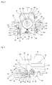
FIG. 1 is a side view showing a first example of an embodiment of the present invention. -
FIG. 2 is a cutaway view seen from the right side ofFIG. 1 wherein a part of the first example is cut away. -
FIG. 3 is a view seen from the opposite side ofFIG. 1 wherein a part of the first example is omitted. -
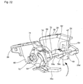
FIG. 4 is a perspective view of the first example seen from the right-underside of the near side ofFIG. 1 -
FIG. 5 is a perspective view showing some components of the first example without other components, seen from the same direction asFIG. 4 . -
FIG. 6 is a perspective view showing some components of the first example without other components, seen from the vertically opposite direction asFIG. 5 . -
FIG. 7 is a perspective view showing some components of the first example drawn from the components shown inFIG. 6 , seen from the same direction asFIG. 6 . -
FIG. 8 is an exploded perspective view of the components shown inFIG. 7 . -
FIG. 9 is an I-I cross-sectional view ofFIG. 2 . -
FIG. 10 includes a side view (A) of an outer column of the first example without other components, seen from the same direction asFIG. 1 , and an end view (B) thereof seen from the right side of (A). -
FIG. 11 is a diagram corresponding to an II-II cross-sectional view ofFIG. 7 for describing a range of regulating the swing angle of a telescoping locking eccentric cam with respect to a support shaft. -
FIG. 12 includes an enlarged view (a) of a section α ofFIG. 1 and a diagram (b) similar toFIG. 11 respectively shown in two ways (A) and (B), for describing a reason that errors can be absorbed by making the telescoping locking eccentric cam capable of swinging with respect to the support shaft. -
FIG. 13 includes an enlarged view (a) of a section α ofFIG. 1 and a diagram (b) similar toFIG. 11 respectively shown in three ways (A) to (C), for describing the variation of positional relationship between both of the tilt-locking eccentric cam and the telescoping locking eccentric cam, and mating members thereof, with rotation of the adjustment lever. -
FIG. 14 is a diagram seen from the same direction asFIG. 1 for describing a stopper mechanism for preventing the tilt-locking eccentric cam from overturning, showing a state (A) of the outer column and the tilt-locking eccentric cam without other components, where this tilt-locking eccentric cam has been turned to one end, and a state (B) where it has been turned to the other end. -
FIG. 15 is a side view of a steering device for a motor vehicle for describing the direction of an impact load applied to each section at the time of a secondary collision. -
FIG. 16 includes an enlarged view (A) of a section β ofFIG. 1 and an enlarged view (B) of a section δ of (A) for describing the movement of the tilt-locking eccentric cam at the time of a secondary collision. -
FIG. 17 includes an enlarged view (A) of a section γ ofFIG. 9 and an enlarged view (B) of a section ε of (A) for describing the movement of the telescoping locking eccentric cam at the time of a secondary collision. -
FIG. 18 includes, for describing the influence of the shape of the telescoping locking convex arc edge on the relationship between the displacement amount of the inner column and the retaining force applied in the direction of preventing the movement of this inner column at the time of a secondary collision, a diagram (A) of the telescoping locking eccentric cam seen from the same direction asFIG. 1 and a graph (B) showing a relationship between the displacement amount and the retaining force. -
FIG. 19 is a graph for describing a relationship between the amount of turning of the adjustment lever and the force for retaining the inner column on the outer column, showing a relationship between the turning amount and the retaining force. -
FIG. 20 is a diagram similar toFIG. 11 , showing a second example of the embodiment of the present invention. -
FIG. 21 is a diagram similar toFIG. 11 , showing a third example of the embodiment of the present invention. -
FIG. 22 shows a fourth example of the embodiment of the present invention being a perspective view showing a state seen from the oblique rear side of some components without other components. -
FIG. 23 is a perspective view showing some components drawn from the components showing inFIG. 22 , seen from the same direction asFIG. 22 . -
FIG. 24 is a III-III cross-sectional view ofFIG. 23 . -
FIG. 25 includes side views for respectively describing a fifth example (A) of the embodiment of the present invention, and a problem (B) which occurs in the case where the present invention is not applied. -
FIG. 26 includes a side view (A) and a partial view (B) seen from the underside of (A), showing a sixth example of the embodiment of the present invention. -
FIG. 27 is a side view showing a seventh example of the embodiment of the present invention. -
FIG. 28 is a perspective view showing an eighth example of the embodiment of the present invention. -
FIG. 29 is an exploded perspective view of the eighth example. -
FIG. 30 is an exploded perspective view showing some components of the eighth example without other components. -
FIG. 31 is a IV-IV cross-sectional view ofFIG. 28 . -
FIG. 32 includes V-V cross-sectional views ofFIG. 31 respectively showing a state (A) where the position of the steering wheel is fixed, and a state (B) where a position adjustment is performed. -
FIG. 33 is a partial cutaway side view showing an example of a steering device for a motor vehicle with the position adjustment device for a steering wheel incorporated therein. -
FIG. 34 is a longitudinal sectional side view showing an example of a conventionally known position adjustment device for a steering wheel. -
FIG. 35 is an enlarged VI-VI cross-sectional view ofFIG. 34 . -
FIG. 36 is a partial side view showing an example of a conventionally known structure for preventing displacement in the position of a steering wheel. -
FIGS. 1 to 19 show a first example of an embodiment of the present invention. A position adjustment device for a steering wheel of the present example, as respectively shown with an overall configuration thereof inFIG. 1 andFIG. 4 , is such that anouter column 13b is supported on asupport bracket 12c so as to be able to be swing-displaced about apivot shaft 11a, to thereby enable a height position adjustment of a steering wheel 1 (refer toFIG. 25 ). Moreover, aninner column 14b is supported on the inner diameter side of theouter column 13b so as to be capable of axial displacement, and further, asteering shaft 5a is rotatably supported on the inner side of thisinner column 14b, thereby enabling an adjustment of the front/rear position of the steering wheel 1. The steeringshaft 5a, as with the structure ofFIG. 25 , combines anouter shaft 15a and aninner shaft 16a so as to be capable of torque transmission as well as extension and retraction. This type ofsteering shaft 5a, with a combination of a single row deep groove type ball bearing and a needle bearing or the like, is supported on the inner diameter side of asteering column 6b composed of theouter column 13b and theinner column 14b, so as to be only rotatable. In this state, the steering wheel 1 can be freely fixed at a portion which projects from a rear end opening of theinner column 14b at the rear end section of theouter shaft 15a constituting thesteering shaft 5a. - The
support bracket 12c combines afront section element 27 and arear section element 28 which are respectively made with a plastic-processed metallic plate such as a steel plate having sufficient strength and rigidity. Theseelements rear section element 28, with respect to thefront section element 27 joined and fixed on a vehicle body, is displaced forward while absorbing impact energy when a secondary collision occurs. Therefore, in the case of the present example, into the rear end section of each oflong holes front section element 27, there is inserted from the upper side abolt 30, and furthermore, both of thesebolts 30 are inserted into both widthwise end side portions of therear section element 28. Both of thesebolts 30 are respectively screwed into a nut 38 (refer toFIG. 4 ), and furthermore, thesebolt 30 and thenut 38 are tightened at a predetermined torque. Moreover, between the abutting surfaces of thefront section element 27 and therear section element 28, there is clamped a slide plate. Furthermore, along hole 32 which is long in the front/rear direction is formed respectively at positions of a pair of mutually parallelside wall sections 31 provided in the upper half section of thefront section element 27 which are aligned with each other. - In the case of the present example, both of end sections of the
pivot shaft 11a are engaged with both of theselong holes 32 so as to be capable of displacement in the front/rear direction. Moreover, between thefront section element 27 and theouter column 13b, there is provided an energy absorbing member which plastically deforms in the direction of extension/retraction to thereby allow theouter column 13b to be displaced forward with respect to thefront section element 27. In the case of the present example, with the type of structure described above, prevention of relative displacement of both of theelements rear section element 28 while absorbing impact energy in a secondary collision can be allowed. - Moreover, a structure in which prevention of relative displacement of both of the
elements rear section element 28 while absorbing impact energy in a secondary collision can be allowed, may be configured by utilizing both of thelong holes 32. In this case, both of theselong holes 32 are such that the widthwise dimension of each rear end section thereof is made greater than that of the intermediate section to the front end section (the portion other than the rear end section for supporting both end sections of thepivot shaft 11a). Furthermore, both of the end sections of thepivot shaft 11a are supported at the rear end section of both of thelong holes 32, and the widthwise dimension of the intermediate section to the front end section of both of theselong holes 32 is made smaller than the outer diameter of both of the end sections of thispivot shaft 11a (or the sleeve section externally fitted on both of the end sections of thepivot shaft 11a). Moreover, both of the end sections of thispivot shaft 11a are supported on the intermediate section in the front/rear direction of both of theside wall sections 31 of thefront section element 27 without allowing rattling in the front/rear direction and up/down direction. A specific operation is described later for both of the structures. - The
outer column 13b is also referred to as a housing member and is fabricated by casting a light metallic material such as aluminum alloy, and it is provided with amain section 33, a pivotedsection 34, and a clampedsection 35 as shown inFIG. 10 for example. Among these, themain section 33 is such that in the bottom end section thereof there is provided, from the rear end section to the intermediate section in the axial direction, a slit-shapednoncontiguous section 36, and thereby the portion excluding the front end section is formed in a segmental cylinder shape. Therefore, the inner diameter of at least the rear end side portion of themain section 33 can be elastically increased and reduced. Moreover, the pivotedsection 34 is provided in a state of projecting upward from the front end section of themain section 33, and both of the outer side surfaces on the left and right are parallel with each other. Furthermore, the clampedsection 35 is provided on the lower surface of the intermediate section of themain section 33 so as to sandwich thenoncontiguous section 36 from both left and right sides and project downward. Further, both of the left and right outer side surfaces are virtually parallel with each other, and the distance between both of these outer side surfaces is greater than the outer diameter of themain section 33. The rear end section side of the slit-shaped noncontiguous is of an open end in the example shown in the diagram. However, this noncontiguous section does not need to be formed from the rear end section of the main section of the outer column, and it may be configured with a closed slit which is axially formed from the vicinity of this rear end section. - The
pivot shaft 11a which is inserted into the rear end section of both of thelong holes 32 at the center section of both of theside wall sections 31, is inserted into a throughhole 37 provided so as to pass through the front end section of the pivotedsection 34 of theouter column 13b in the widthwise direction (refer toFIG. 10 andFIG. 14 ). Moreover, with a head section with a large diameter provided in the base end section of thepivot shaft 11a, and a nut screwed on a tip end section thereof, thispivot shaft 11a is prevented from falling out. With this configuration, theouter column 13b is supported on thesupport bracket 12c so as to be capable of swing displacement about thepivot shaft 11a. - On the other hand, the
rear section element 28 is such that as shown inFIG. 1 to 3 and5 and6 for example, a pair of left andright support plates 40 are provided parallel with each other in a state of hanging downward from the rear half section of a pair ofattachment plate sections 39 for attaching thisrear section element 28 to the rear end section lower surface of thefront section element 27. In portions of both of thesesupport plates 40 which are aligned with each other, there is respectively formed along hole 41 which is long in a direction of an arc about thepivot shaft 11a (diagonally upward-downward direction). As shown inFIG. 4 to FIG. 6 for example, a rod-shapedmember 19a is inserted through both of theselong holes 41 and throughholes 77 provided so as to pass through each of the clampedsections 35 of theouter column 13b in the left/right direction (refer toFIG. 9 ,10 , and14 ). The rod-shapedmember 19a is to increase and reduce the distance between the mutually opposing surfaces of both of thesupport plates 40 in response to rotation, and both of the end sections thereof project from the outer side surface of both of thesesupport plates 40. The base section of anadjustment lever 18a is joined and fixed on the base end section of the rod-shapedmember 19a (left end section inFIGs. 4 to 6 ), and the outer side surface of apresser plate 42 externally fitted on the tip end section (right end section inFIGs. 4 to 6 ) is pressed with anut 43, to thereby prevent thispresser plate 42 from falling off. - Furthermore, a cam device 20 (refer to
FIG. 35 ) is provided between the inner side surface of the base end section of theadjustment lever 18a and the outer side surface of one (left side inFIGs. 4 to 6 ) of thesupport plates 40, so as to be capable of increasing and reducing the distance between both of the side surfaces in response to turning of theadjustment lever 18a. When performing a position adjustment of the steering wheel 1, as shown inFIG. 13 (C) (a) , theadjustment lever 18a is turned downward to thereby reduce the distance between the inner side surface of the base end section of theadjustment lever 18a and the outer side surface of the onesupport plate 40. Consequently, the distance between the inner side surfaces of the pair ofsupport plates 40 is elastically increased, and the surface pressure of the contact section between the inner side surface of both of thesesupport plates 40 and the outer side surface of the clampedsection 35 of theouter column 13b is lowered or lost, making position adjustment of the steering wheel 1 possible. Having adjusted the position, if theadjustment lever 18a is turned upward as shown inFIG. 13 (A) (a) , the distance between the inner side surfaces of both of thesupport plates 40 is reduced, instead of the distance being increased between inner side surface of the base end section of theadjustment lever 18a and the outer side surface of the onesupport plate 40. Accordingly, the surface pressure of the contact section between the inner side surface of both of thesesupport plates 40 and the outer side surface of the clampedsection 35 of theouter column 13b becomes greater, and the steering wheel 1 is supported at a post-adjustment position. In order to increase or reduce the above distance, it is sufficient that a pair of cam members which constitutes thecam device 20 is relatively displaced from each other in the rotation direction in response to turning of theadjustment lever 18a. The rod-shapedmember 19a may rotate together with theadjustment lever 18a. However, it does not always have to rotate, and it may be only axially displaced without rotating. The structure for increasing and reducing the distance between the pair of support plates in response to rotation of the rod-shaped member, is not limited to a cam device, and various types of conventionally known devices such as screw mechanism may also be employed therefor. The above configuration and operation are similar to those of the conventionally known position adjustment device for a steering wheel. - Furthermore, in the case of the structure of the present example, as described below, displacement of the position of the steering wheel 1 at the time of a secondary collision is prevented, and in addition, unpleasant noise or vibration do not occur at the time of adjusting the position of this steering wheel 1. For this reason, as shown in
FIG. 10 for example, a pivotingconvex section 44 is provided on a rear end surface of the clampedsection 35 of theouter column 13b, so as to project backward from this clampedsection 35. Also this pivotingconvex section 44 is provided in a state of sandwiching thenoncontiguous section 36 from both sides in the widthwise direction. Moreover, as shown inFIG. 10(B) , the widthwise dimension W44 of the pivotingconvex section 44 is smaller than the widthwise dimension W35 of the clamped section 35 (W44 < W35). Therefore, both of the widthwise end sections of the rear end surface of this clampedsection 35 are of astep surface 45. Both of these step surfaces 45 function as a stopper section. - In a through
hole 46 respectively formed in a state of passing in the widthwise direction through the respective pivotingconvex sections 44, there is rotatably inserted asupport shaft 47. Thissupport shaft 47 is arranged parallel with the rod-shapedmember 19a, and as shown inFIG. 8 for example, the base end section thereof (left end section inFIG. 8 ) has ahead section 48 while the tip end section thereof (right end section inFIG. 8 ) has amale screw section 49. Moreover, the portion between thehead section 48 and themale screw section 49 comprises, respectively from thishead section 48 side, a large diameter sidenon-columnar section 50, acolumnar section 51, and a small diameternon-columnar section 52. Tilt-lockingeccentric cams non-columnar sections respective sections 50 to 52, in a state where relative rotation with respect to the support shaft 7 is prevented, that is, where it rotates in synchronization with thesupport shaft 47. - In a state where the position adjustment device for a steering wheel is assembled, a widthwise outer half section of both of the tilt-locking
eccentric cams support plates 40 provided on therear section element 28 of thesupport bracket 12c. The rear end edge of both of thesesupport plates 40 is of acurved edge 53 having a shape of a convex arc about thepivot shaft 11a. Therefore, even in a case where thesupport shaft 47 is lifted or lowered with respect to therear section element 28 in response to an up/down position adjustment of the steering wheel 1, the distance between thissupport shaft 47 and both of thecurved edges 53 will not change. Moreover, a portion of the outer periphery portion of both of the tilt-lockingeccentric cams curved edges 53 is, as shown inFIG. 1 ,3 , and16 for example, of a tilt-locking convex arc edge angled in a direction in which the distance from the center of thesupport shaft 47 increases, that is, the center thereof is biased upward from the center of thesupport shaft 47, with upward approach, in a state where the position of the steering wheel 1 is fixed. Moreover, a tilt-lockingserrated section 54 is formed on this tilt-locking convex arc edge. This tilt-lockingserrated section 54 is of a sawtooth shape or triangular wave shape. Furthermore, on the outer periphery section of the one (left side inFIG. 4 to 8 ) tilt-lockingeccentric cam 23a, there is formed a drivenarm section 57 so as to project radially outward. - Furthermore, in the case of the structure of the present example, as shown in
FIG. 1 ,3 , and16 for example, in the portions of the outer periphery portion of both of the tilt-lockingeccentric cams serrated section 54 from both sides around the circumferential direction, there are provided astopper 55 for preventing overturning at the time of a collision and astopper 56 for preventing overturning at the time of an adjustment. Thestopper 55 for preventing overturning at the time of a collision is provided in a portion adjacent to the upper side (large diameter side end section) of the tilt-lockingserrated section 54, and the top section thereof is present at an approximate tangential position of the outer diameter side end section of this tilt-lockingserrated section 54. Meanwhile, thestopper 56 for preventing overturning at the time of an adjustment is provided in a portion slightly distanced in the circumferential direction from the lower end section (small diameter side end section) of the tilt-lockingserrated section 54, so as to sufficiently project from this portion. In the state where the position adjustment device for a steering wheel is assembled, a widthwise inner half section of thestopper 56 for preventing overturning at the time of an adjustment is opposed to or is in contact with the step surface 45 (widthwise phases are matched). Both of the tilt-lockingeccentric cams rear section element 28 of thesupport bracket 12c such as low carbon steel and aluminum based alloy. - On the other hand, a telescoping locking
eccentric cam 58 is, at the intermediate section of thesupport shaft 47, externally fitted on the end section closer to thecolumnar section 51 of the large diameter sidenon-columnar section 50 with a structure shown inFIG. 11 , so as to be capable of relative rotation with respect to thesupport shaft 47 only by a predetermined angle. In the state where the position adjustment device for a steering wheel is assembled, the telescoping lockingeccentric cam 58 slots into thenoncontiguous section 36 of theouter column 13b, and becomes opposed to the outer circumferential surface of theinner column 14b (lower surface in the case of the present example). In the case of the present example, the large diameter sidenon-columnar section 50 is of a cross-sectionally oval shape having a pair of mutually parallel flat surfaces 59. Moreover, anattachment hole 60 formed in the base section of the telescoping locking eccentric cam 58 (left section inFIG. 11 ) is of a noncircular shape, the basic shape of which is a circular shape, and which is formed in a state where a bank-shapedprojection section 61 is formed at two positions on sides opposed to each other in the radial direction so as to project radially inward. Based on the engagement between both of theseprojection sections 61 and both of theflat surfaces 59, the telescoping lockingeccentric cam 58 is capable of rotating about the neutral position shown inFIG. 11 , with respect to the rod-shapedmember 19a, only by θ1 in the counterclockwise direction and only by θ2 in the clockwise direction. Both of these angles θ1 and θ2 do not have to be the same, however, they may be the same angle. - In the case of the present example, by setting both of these angles θ1 and θ2, the positional relationship between the telescoping locking
eccentric cam 58 and theinner column 14b can be made appropriate without the need for ensuring a high level of precision in the shape and assembly of the respective constituent members. That is to say, there is a possibility that in the state where the positional relationship between both of the tilt-lockingeccentric cams curved edges 53 is appropriately restricted, the relationship between thesupport shaft 47 and the telescoping lockingeccentric cam 58 may become as shown inFIG. 12 (A) or as shown inFIG. 12 (B) . Even in this case, by setting both of the angles θ1 and θ2, positional displacement between thesupport shaft 47 and the telescoping lockingeccentric cam 58 can be absorbed, and therefore, there is no need for ensuring a high level of precision in the shape and assembly of the respective constituent members. As a result, manufacturing cost can be suppressed. - In the state where the position adjustment device for a steering wheel is assembled, the telescoping locking
eccentric cam 58 slots into thenoncontiguous section 36 of theouter column 13b, and becomes opposed to or comes in contact with the outer circumferential surface of theinner column 14b (lower surface in the case of the present example). A portion of the outer periphery section of this type of telescoping lockingeccentric cam 58 which opposes to the outer circumferential surface of theinner column 14b, is angled in a direction in which the distance from the center of thesupport shaft 47 becomes greater with backward approach, and it is of a telescoping locking convex arc edge, the center O62 of which is biased backward-downward from the center O47 of thesupport shaft 47 as shown inFIG. 18 . Moreover, a telescoping lockingserrated section 62 is formed on the telescoping locking convex arc edge. This telescoping lockingserrated section 62 is also of a sawtooth shape or triangular wave shape as with the tilt-lockingserrated section 54. Furthermore, in the case of the structure of the present example, in a portion of the outer periphery portion of the telescoping lockingeccentric cam 58 which departs backward from the large diameter side end section of the telescoping lockingserrated section 62, there is provided astopper 63 for preventing overturning at the time of a collision, so as to sufficiently project backward from this portion. This type of telescoping lockingeccentric cam 58 is also fabricated with a metallic material, such as medium carbon steel, high carbon steel, carburized steel, and bearing steel, harder than the metallic material which constitutes theinner column 14b such as low carbon steel and aluminum based alloy. - Between the telescoping locking
eccentric cam 58 and thesupport shaft 47 described above, as shown inFIG. 4 ,8 , and17 for example, there is provided a telescopinglocking biasing spring 64, which is a first spring. This telescopinglocking biasing spring 64 is formed with a bent spring steel wire rod, and it is provided with abase section 65 which can be externally fitted on the large diameter sidenon-columnar section 50 of thesupport shaft 47 in a state of preventing relative rotation and the shape of which seen in the axial direction is oval, anelastic presser section 66 which projects radially outward from thisbase section 65, and anengagement section 67 formed with the tip end section of thiselastic presser section 66 which is bent in a crank shape. This type of telescopinglocking biasing spring 64 is such that thebase section 65 is externally fitted on the large diameter sidenon-columnar section 50, and theengagement section 67 is engaged with anengagement hole 68 formed in the rear end section of the telescoping lockingeccentric cam 58, to thereby span between the telescoping lockingeccentric cam 58 and thesupport shaft 47. In this state, this telescoping lockingeccentric cam 58 is given an elastic force in a direction of turning about thesupport shaft 47 and pressing the telescoping lockingserrated section 62 against the lower surface of theinner column 14b (counterclockwise direction inFIG. 4 to 7 ,9, 11 to 13, 16, and 17 ). - Furthermore, between the
adjustment lever 18a and thesupport shaft 47, there is provided a turningforce transmission spring 69 which serves as a second spring (joining member), to enable transmission of the movement of thisadjustment lever 18a to thesupport shaft 47. In the case of the present example, the turningforce transmission spring 69 is such that it is configured by bend-forming a spring steel wire rod, in a base end side portion thereof there is formed a drivingside engagement section 71 to be engaged with a driving side engagement hole 70 (refer toFIG. 1 ,6 ,12 , and13 ) provided in the base end section of theadjustment lever 18a, and in a tip end section thereof there is formed a drivenside engagement section 73 to be engaged with a drivenside engagement hole 72 formed in the tip end section of the drivenarm section 57 of the tilt-lockingeccentric cam 23a. Moreover, in the intermediate section thereof there is provided acoil section 74 for ensuring a flexible volume. By respectively engaging the drivingside engagement section 71 with the drivingside engagement hole 70 and engaging the drivenside engagement section 73 with the drivenside engagement hole 72, theadjustment lever 18a and thesupport shaft 47 are joined via the tilt-lockingeccentric cam 23a and the turningforce transmission spring 69, to thereby enable transmission of the movement of theadjustment lever 18a to thesupport shaft 47. Thecoil section 74 is provided to give an appropriate elastic force to the tilt-lockingeccentric cam 23a regardless of manufacturing errors to a certain degree. - With this type of configuration, when the
adjustment lever 18a is turned upward as shown inFIG. 13 (A) (a) and the position of the steering wheel 1 is fixed, thesupport shaft 47 is turned in the counterclockwise direction inFIG. 4 to 7 ,9, 11 to 13 ,16 , and17 . In response to this turning, the lower end section to the intermediate section of the tilt-lockingserrated section 54 of the pair of tilt-lockingeccentric cams support shaft 47, are respectively butted on thecurved edge 53 on the support bracket side, and the front end side portion of the telescoping lockingserrated section 62 of the telescoping lockingeccentric cam 58 supported on the intermediate section of thesupport shaft 47 is butted on the lower surface of theinner column 14b. - The position adjustment device for a steering wheel of the present example configured as described above operates in a manner described below, so as to enable an adjustment of the up/down position and front/rear position of the steering wheel 1, and suppress upward or forward displacement of the position of the steering wheel 1 at the time of a secondary collision, to thereby achieve enhanced protection of a driver colliding with this steering wheel 1.
- First, when adjusting the position of the steering wheel 1, the
adjustment lever 18a is turned from the state shown inFIG. 13 (A) (a) to the state shown inFIG. 13 (C) (a) in the clockwise direction in the same diagrams. As a result, with the operation of the cam device as described above, the surface pressure of the contact section between the inner side surface of both of thesupport plates 40 and the outer side surface of the clampedsection 35 of theouter column 13b, is lowered or lost. - Moreover, in this state, since the
support shaft 47 also turns in the clockwise direction ofFIG. 13 , the tilt-lockingeccentric cams eccentric cam 58 supported on thissupport shaft 47, also turn in the clockwise direction of the same diagram. As shown inFIG. 13 (C) (a) andFIG. 14 (B) , the entire tilt-lockingserrated section 54 becomes separated from thecurved edge 53. Furthermore, in this state, it turns beyond a stroke with which the telescopinglocking biasing spring 64 loses its elastic force pressing the telescoping lockingeccentric cam 58 against the lower surface of theinner column 14b. As a result, as shown inFIG. 13 (C) (b) , the entire telescoping lockingserrated section 62 of the telescoping lockingeccentric cam 58 becomes separated from the lower surface of theinner column 14b. In this state, an adjustment of the up/down position and front/rear position of the steering wheel 1 becomes possible. An up/down position adjustment is performed by moving the rod-shapedmember 19a along thelong hole 41 of both of thesupport plates 40 while swing-displacing theouter column 13b about thepivot shaft 11a. Moreover, a front/rear position adjustment is performed by axially sliding theinner column 14b on theouter column 13b. - In the case of the present example, a
stopper 56 for preventing overturning at the time of an adjustment is provided on the tilt-lockingeccentric cams stopper 56 for preventing overturning at the time of an adjustment and both of the step surfaces 45 serving as a stopper section, the turning amount of both of the tilt-lockingeccentric cams adjustment lever 18a is turned downward in order to make a position adjustment of the steering wheel 1, as shown inFIG. 13 (C) (a) andFIG. 14 (B) , the tip end section of thestopper 56 for preventing overturning at the time of an adjustment of the tilt-lockingeccentric cam 23a (23b) is butted against thestep surface 45 present on the outer side surface of theouter column 13b. In this state, the entire tilt-lockingeccentric cam 23a (23b) becomes separated from thecurved edge 53 of thesupport plate 40. For this reason, even if the operating amount of theadjustment lever 18a becomes excessive, that is, even if it is excessively turned downward, both of the tilt-lockingeccentric cams FIG. 13 . As a result, in the state where theadjustment lever 18a is turned downward, part of both of the tilt-lockingeccentric cams curved edge 53 of both of thesupport plates 40 do not interfere with each other, and a smooth adjustment of the up/down position of the steering wheel 1 can be performed without giving the driver a sense of discomfort. - Having adjust the steering wheel 1 to a required position as described above, the
adjustment lever 18a is swung upward in a direction opposite to the predetermined direction (in the counterclockwise direction inFIG. 13 ) until theadjustment lever 18a becomes substantially parallel with theouter column 13b and theinner column 14b as shown inFIG. 1 andFIG. 13 (A) (a) for example. As a result of this swing in the opposite direction, with the operation of the cam device described above, both of thesupport plates 40 firmly clamp theouter column 13b from both sides in the widthwise direction, and the up/down position of the steering wheel 1 is fixed. At the same time, as a result of reduction in the widthwise dimension of thenoncontiguous section 36, the inner diameter of theouter column 13b is reduced, and the inner circumferential surface of thisouter column 13b is firmly pressed against the outer circumferential surface of theinner column 14b. Further, relative displacement in the axial direction between both of thesecolumns - As described above, in the state where the
adjustment lever 18a is swung upward until the position of the steering wheel 1 is fixed, the turningforce transmission spring 69 rotates thesupport shaft 47 in the same direction as theadjustment lever 18a (counterclockwise direction inFIG. 13 ). As shown inFIG. 13 (A) (a) , a lower end side portion of the tilt-locking convex arc edge (tilt-locking serrated section 54) of the tilt-lockingeccentric cam 23a (23b) in which the distance from the center of thesupport shaft 47 is shortest, comes in contact with thecurved edge 53 provided on the rear end edge of both of thesupport plates 40. Moreover, as shown inFIG. 13 (A) (b) , a front end portion of the telescoping locking convex arc edge (telescoping locking serrated section 62) of the telescoping lockingeccentric cam 58 in which the distance from the center of thesupport shaft 47 is shortest, comes in contact with the outer circumferential surface (lower surface) of the lower end section of theinner column 14b. - In the state where the
adjustment lever 18a is turned upward as shown inFIG. 13 (A) (a) , the force of both of thesupport plates 40 clamping theouter column 13b becomes an appropriate value, and at the same time, the lower end section to intermediate section (lower end side portion) of the tilt-lockingserrated section 54 of both of the tilt-lockingeccentric cams curved edge 53 on the support bracket side. Furthermore, the front end side portion of the telescoping lockingserrated section 62 of the telescoping lockingeccentric cam 58 needs to be butted against the lower surface of theinner column 14b. In the above operation, the lower end section to intermediate section of the tilt-lockingserrated section 54 can be easily butted against thecurved edge 53 on the support bracket side while bringing the clamping force to an appropriate value, by adjusting the axial position of thepresser plate 42, using thenut 43 screwed on themale screw section 49 of the tip end of the rod-shape member 19a. - However, in the case where the telescoping locking
eccentric cam 58 is on thesupport shaft 47, a high level of precision is required in the shape, dimension, and assembly of the respective sections in order to strictly restrict also the positional relationship between the telescoping lockingserrated section 62 and theinner column 14b. As a result, cost increases. In contrast, in the case of the present example, as described usingFIG. 11 , since the telescoping lockingeccentric cam 58 is supported on thesupport shaft 47 while being capable of slight swing displacement, it is possible, without requiring a particularly high level of precision in the respective sections, to realize, at low cost, a position adjustment device for a steering wheel which achieves an appropriate engagement relationship between the respective members as mentioned above and which is capable of reliably obtaining required performance when fixing the position of the steering wheel 1. - For example, in the state where the
adjustment lever 18a is turned to θ3 (θ3 < θ4) as shown inFIG. 13 (B) between the state shown inFIG. 13 (A) where the position of the steering wheel 1 is completely fixed (turning amount = 0) and the state shown inFIG. 13 (C) where theadjustment lever 18a is turned to θ4 and a position adjustment of the steering wheel 1 is possible, it is preferable to tune the respective sections so that the position of the steering wheel 1 does not move, but the respective lockingserrated sections adjustment lever 18a and the force of retaining theinner column 14b with respect to theouter column 13b, is made as shown inFIG. 19 . In the case where the turning amount is from 0 to θ3, the respective lockingserrated sections serrated sections eccentric cam 58 is supported on thesupport shaft 47 while being capable of slight swing displacement as described above, the type of tuning mentioned above can be easily conducted. - As shown in
FIG. 1 andFIG. 13 (A) (a) , if a forward-upward impact load is applied to theinner column 14b and theouter column 13b at the time of a secondary collision in a state where the position of the steering wheel 1 is fixed, displacement of the position of the steering wheel 1 is prevented as described below. First, upward displacement motion of the steering wheel 1 can be suppressed by the tilt-lockingserrated section 54 provided on the tilt-locking convex arc edge of both of the tilt-lockingeccentric cams 23a (23b) interlocking with thecurved edge 53 of thesupport plate 40. That is to say, at the time of a secondary collision, if theouter column 13b tends to be displaced upward with respect to thesupport bracket 12c having thesupport plate 40 provided thereon, the tilt-lockingeccentric cam 23a (23b) tends to turn about thesupport shaft 47 in the direction illustrated with the arrow inFIG. 16 (A) , based on the interlocking between thecurved edge 53 and both of the tilt-lockingserrated section 54. - For this reason, a portion of the tilt-locking
serrated section 54 which is interlocking with thecurved edge 53, tends to move to the upper side of this tilt-lockingserrated section 54, that is, it tends to move to the portion in which the distance from the center of thesupport shaft section 47 is long. As a result, as shown inFIG. 16 (B) , the depth of interlocking of the tilt-lockingserrated section 54 with respect to thecurved edge 53 gradually becomes greater. Since large resistance acts with respect to the depth of interlocking becoming greater in this way, it is possible to suppress upward displacement of the steering wheel 1. If the level of impact load in a secondary collision is high and the turning amount of the tilt-lockingeccentric cam 23a (23b) is high, thestopper 55 for preventing overturning at the time of a collision is butted against thecurved edge 53, and the tilt-lockingeccentric cam 23a (23b) will not turn any further. In this state, the force of suppressing upward displacement of the steering wheel 1 becomes sufficiently large, and the steering wheel 1 will not be displaced upward any further. The material of the tilt-lockingeccentric cam 23a (23b) is harder than that of therear section element 28, and therefore, this type of interlocking is performed reliably. - Moreover, when the
inner column 14b tends to be displaced forward, a portion of the telescoping lockingserrated section 62 which is interlocking with the lower surface of theinner column 14b, tends to move to the rear side of this telescoping lockingserrated section 62, that is, it tends to move to the portion in which the distance from the center of thesupport shaft section 47 is long. As a result, as shown inFIG. 17 (B) , the depth of interlocking of the telescoping lockingserrated section 62 with respect to the lower surface of theinner column 14b gradually becomes greater. Since large resistance acts with respect to the depth of interlocking becoming greater in this way, it is possible to suppress forward displacement of the steering wheel 1. If the level of impact load in a secondary collision is high and the turning amount of the telescoping lockingeccentric cam 58 is high, thestopper 63 for preventing overturning at the time of a collision is butted against the lower surface of theinner column 14b, and the telescoping lockingeccentric cam 58 will not turn any further. In this state, the force of suppressing forward displacement of the steering wheel 1 becomes sufficiently large, and the steering wheel 1 will not be displaced forward any further. The material of the telescoping lockingeccentric cam 58 is harder than that of theinner column 14b, and therefore, this type of interlocking is performed reliably. - As a result, a large force acts to prevent forward-upward displacement of the steering wheel 1, and it is possible to effectively prevent the position of this steering wheel 1 from being displaced. At this time, the force required for interlocking the tilt-locking
serrated section 54 of the tilt-locking ride arc edge with thecurved edge 53, and the force required for interlocking the telescoping lockingserrated section 62 of the telescoping locking convex arc edge with the lower surface of theinner column 14b, are respectively small in the initial stage and gradually become greater. This type of characteristic is preferable in terms of protecting the driver by absorbing impact energy transmitted from the steering wheel 1 to theinner column 14b and theouter column 13b. That is to say, it is advantageous from the viewpoint that; while suppressing an impact applied to the body of the driver to a low level at the moment of secondary collision occurrence, the force of supporting the body of this driver can be gradually increased, and the level of freedom in tuning for enhanced driver protection can be ensured. - As described above, the magnitude of the force which acts in the direction of stopping the movement of the steering wheel 1 in the initial step of a secondary collision can be adjusted based on the degree of changes in the diameter of the respective tilt-locking
serrated section 54 and telescoping lockingserrated section 62. This point is described with reference toFIG. 18 , taking an example of the telescoping lockingserrated section 62. In thisFIG. 18 (A) , the broken line arc κ passes the tooth top of the small diameter side end section of the telescoping lockingserrated section 62, taking the center O47 of thesupport shaft 47 as the center thereof. Moreover, the chain line arc λ which passes all of the tooth tops of the telescoping lockingserrated section 62 takes the point O62 as the center thereof. The distance C between the broken line arc κ and the change line arc λ in the state where the telescoping lockingeccentric cam 58 is turned only by θa in the counterclockwise direction inFIG. 18 (A) in response to a secondary collision, can be arbitrarily adjusted based on the eccentricity amount of between both of the centers O47 and O62, and the difference in the diameter between both of the arcs κ and λ. Moreover, the turning amount θb from the moment of the start of the secondary collision to the moment at which thestopper 63 for preventing overturning at the time of a collision is butted against the lower surface of theinner column 14b and the telescoping lockingeccentric cam 58 is not turned any further, can be arbitrarily adjusted based on the dimension and shape of thestopper 63 for preventing overturning at the time of a collision. - For example, the solid line in
FIG. 18 (B) shows a relationship, in a state where a standard distance C and a turning amount θb is set, between the forward displacement amount (movement amount) X of theinner column 14b in response to a secondary collision, and the resistance (retaining force) F with respect to this forward displacement of theinner column 14b. The retaining force in the initial step is obtained by friction between the inner side surface of both of thesupport plates 40 and the outer side surface of the clampedsection 35, which occurs in response to tightening of theadjustment lever 18a. The retaining force on the right side to the first bending point, which is the next step, is obtained by, in addition to this friction, resistance against the progress of interlocking between the telescoping lockingserrated section 62 and the lower surface of theinner column 14b. The degree of this type of increase in the retaining force on the next step can be adjusted based on the relationship between the rotation angle θa and the distance C. The retaining force on the right side to the second bending point, which is the further next step, is obtained by, in addition to the above friction, resistance with respect to the telescoping lockingserrated section 62 interlocked with the lower surface of theinner column 14b, shaving off the surface layer portion of thisinner column 14b. The position of the second bending point can be adjusted based on the turning amount θb. - In any case, the retaining force increases as described above, and if it exceeds the supporting force (breakaway load) of the
rear section element 28 with respect to thefront section element 27, thisrear section element 28 starts to be displaced forward together with theouter column 13b regardless of the interlocking between the telescoping lockingserrated section 62 and the lower surface of theinner column 14b. At this time, the energy absorbing member spanning between thefront section element 27 and theouter column 13b is extended. Alternatively, while increasing the widthwise dimension of the intermediate section to the front end section of both oflong holes 32 by both end sections of thepivot shaft 11a, theouter column 13b is displaced forward together with thispivot shaft 11a. In any case, the steering wheel 1 is displaced forward while mitigating the impact energy applied to the body of the driver collided with the steering wheel 1. - In the present invention, as opposed to the illustrated example, the telescoping locking eccentric cam may be fixed on the intermediate section of the support shaft, and the pair of tilt-locking eccentric cams may be supported on both of the end sections of this support shaft so as to be capable of swing displacement with respect to this support shaft. In this case, a rotational force transmission spring serving as the second spring is spanned between the adjustment lever and the telescoping locking eccentric cam, and a tilt-locking biasing spring serving as the first spring is provided between both of the tilt-locking eccentric cams and the support shaft.
- Moreover, as for the structure for adjusting the up/down position and front/rear position of the steering wheel, it is not limited to the structure illustrated in the diagram, and various types of conventionally known structures may be employed therefor. Furthermore, in a case where the outer column is arranged on the rear side and the inner column is arranged on the front side, the telescoping locking serrated section may be engaged with part of the outer circumferential surface of the outer column.
-
FIG. 20 shows a second example of the embodiment of the present invention. In the case of the present example, acircular attachment hole 60a provided in the base section of a telescoping lockingeccentric cam 58a is rotatably engaged with thesupport shaft 47. A telescopinglocking biasing spring 64 serving as a first spring restricts the turning amount of the telescoping lockingeccentric cam 58a with respect to thesupport shaft 47. That is to say, in the state where theadjustment lever 18a is turned downward in order to perform a position adjustment of the steering wheel 1, the telescopinglocking biasing spring 64 separates the telescoping lockingserrated section 62 of the telescoping lockingeccentric cam 58a from the lower surface of theinner column 14b. - In this type of structure of the present example, only the telescoping
locking biasing spring 64 restricts the turning amount of the telescoping lockingeccentric cam 58a with respect to thesupport shaft 47. Therefore, in order to reliably engage or disengage the telescoping lockingserrated section 62 with or from the lower surface of theinner column 14b, it is necessary to ensure precision (shape precision and elastic deformation amount) of the telescopinglocking biasing spring 64. However, as long as this precision is ensured, the operation of inserting thesupport shaft 47 into theattachment hole 60a becomes easy, and it is therefore possible to achieve cost reduction by improving the level of assemblability. The structure and operation of other portions are similar to those of the first example of the embodiment, and illustration and description of the similar portions are therefore omitted. -
FIG. 21 shows a third example of the embodiment of the present invention. In the case of the present example, anelastic material 75 composed of rubber, elastomer, or the like intervenes between the inner circumferential surface of theattachment hole 60 provided in the base section of a telescoping lockingeccentric cam 58b, and the outer circumferential surface of thesupport shaft 47, instead of the telescopinglocking biasing spring 64 serving as the first spring. Both of these circumferential surfaces are of a cross-sectional oval shape having flat surfaces parallel with each other, and the telescoping lockingeccentric cam 58b can be swing-displaced only by a predetermined angle with respect to thesupport shaft 47, while elastically deforming a portion of theelastic material 75 present between the flat surfaces parallel with each other. This type of structure of the present example is such that not only the telescopinglocking biasing spring 64 can be omitted, but also a portion which engages with the end section of this telescopinglocking biasing spring 64 does not need to be provided on the end section of the telescoping lockingeccentric cam 58b. As a result, it is possible to reduce the size, weight, and cost of the position adjustment device for a steering wheel. Furthermore, the cross-sectional shape of the circumferential surface of any one of both of the circumferential surfaces may be a circular shape, and this circumferential surface and theelastic material 75 may be adhered to each other by means of baking or the like. The structure and operation of other portions are similar to those of the first example of the embodiment, and illustration and description of the similar portions are therefore omitted. -
FIG. 22 to 24 show a fourth example of the embodiment of the present invention. In the case of the present example, a telescopinglocking biasing spring 64a serving as the first spring is spanned between the tip end sections of tilt-lockingeccentric cams support shaft 47. This telescopinglocking biasing spring 64a is a spring steel-made linear wire rod, and the intermediate section thereof is inserted into a small throughhole 76 formed in the tip end section of a telescoping lockingeccentric cam 58c. In a state where thesupport shaft 47 is swung in a direction of the arrow inFIG. 22 andFIG. 23 as theadjustment lever 18a is turned upward in order to fix the position of the steering wheel 1, this type of telescopinglocking biasing spring 64a is bent in a curvature direction to thereby press the telescoping lockingserrated section 62 provided on the telescoping lockingeccentric cam 58c against the lower surface of theinner column 14b. That is to say, in the case of the present example, the telescopinglocking biasing spring 64a is provided, via both of the tilt-lockingeccentric cams eccentric cam 58c and thesupport shaft 47. The structure and operation of other portions are similar to those of the first example of the embodiment described above, and illustration and description of the similar portions are therefore omitted. -
FIG. 25 (A) shows a fifth example of the embodiment of the present invention. In the case of the present example, a clampedsection 35a is provided on the upper surface of anouter column 13c, and respective members, including the rod-shapedmember 19a and thesupport shaft 47, for controlling whether or not a position adjustment of the steering wheel 1 can be made, are arranged above theouter column 13c. This type of structure is effective from the viewpoint that the portion largely projecting downward from part of thisouter column 13c is eliminated to thereby protect the knee part of the driver in the event of a collision accident. However, in this type of structure, as shown inFIG. 25 (B) , in the state where theadjustment lever 18a is turned downward in order to perform a position adjustment of the steering wheel 1, the tilt-lockingeccentric cam 23d, due to its own weight, is likely to come in contact with acurved edge 53a of asupport plate 40a of asupport bracket 12d, depending on the angle θ of assembly to the vehicle and the arrangement of the tilt-lockingeccentric cam 23d. Consequently, in the case of the structure of the present example, a portion in which the base section of the tilt-lockingeccentric cam 23d is pivoted on both left and right side surfaces of the clampedsection 35a, is indented in the widthwise direction, and below this portion, there is provided astep surface 45a which functions as a stopper section. In the state where theadjustment lever 18a is turned downward, the downward turning amount of the tilt-lockingeccentric cam 23d is limited based on the engagement with thestep surface 45a, to thereby prevent this tilt-lockingeccentric cam 23d from coming in contact with thecurved edge 53a. The configuration and operation of other portions are similar to those of the first example of the embodiment except that the direction of displacement of each section is restricted in accordance with the above respective members being arranged above theouter column 13c, and therefore, illustration and description of the similar portions are omitted. -
FIG. 26 shows a sixth example of the embodiment of the present invention. Whereas theouter columns main body 78, apivot bracket 79, which serves as a pivoted section, and a lifting and loweringbracket 80, which serves as a clamped section, are all fabricated by bend-forming a metallic plate. Apivot bracket 79 is join-fixed on the upper surface of a front end section of the steering columnmain body 78, and the lifting and loweringbracket 80 is join-fixed on the lower surface of an intermediate section of the same. At the same time, astep surface 45b which serves as a stopper section for regulating turning of the tilt-lockingeccentric cam 23d when making a position adjustment of the steering wheel 1, is fabricated by bend-forming the metallic plate constituting the lifting and loweringbracket 80 in a cross-sectionally crank shape. The structure of the present example is intend to be practiced in a structure which has only a tilt function and does not have a telescoping function. However, it may be provided with a telescoping function by making the diameter of a part of the steering columnmain body 78 increasable and reducable. The structure and operation of other portions are similar to those of the fifth example of the embodiment, and illustration and description of the similar portions are therefore omitted. -
FIG. 27 shows a seventh example of the embodiment of the present invention. In the case of the present example, aprojection section 81 is provided on both side surfaces of a clampedsection 35b of anouter column 13d, so as to serve as a stopper section which restricts turning of the tilt-lockingeccentric cam 23c when performing a position adjustment of the steering wheel 1. Theprojection section 81 may be integrally formed with thisouter column 13d when casting theouter column 13d, and in addition, it may also be formed by driving in a pin or screwing it in afterwards. Moreover, theprojection section 81 may be of a shape such as hemispherical shape or a truncated cone shape in addition to a columnar shape, as long as it is capable of restricting turning of the tilt-lockingeccentric cam 23d by its engagement therewith. The structure and operation of other portions are similar to those of the fifth example of the embodiment, and illustration and description of the similar portions are therefore omitted. -
FIG. 29 to 32 show an eighth example of the embodiment of the present invention. A telescopic steering device of the present example is, in addition to a telescopic mechanism for adjusting the front/rear position of the steering wheel 1 (refer toFIG. 33 ), provided with a tilt mechanism for adjusting the up/down position. - In the case of the present example, in order to configure the telescopic mechanism, in the inner diameter side of an
outer column 13e, which is generally referred to as the housing section, there is inserted a rear half section of aninner column 14c capable of extending and retracting itself, so as to be capable of displacement in the axial direction (diagonally front/rear direction). Thisinner column 14c is such that a rear end section of a cylindrical fronthalf element 83 having a comparatively small diameter, and a front end section of a cylindricalrear half element 84 having a comparatively large diameter are fitted together in a telescopic shape so as to be capable of displacement in the axial direction, and it is thus capable of extension and retraction. Apivot bracket 79a is fixed on a front end section of this type ofinner column 14c, and thispivot bracket 79a is supported on the vehicle body so as to be capable of swing displacement about thepivot shaft 11 arranged in the widthwise direction (refer toFIG. 33 and34 ). Further, the height position of the steering wheel 1 can be adjusted based on this swing displacement. That is to say, in the case of the present example, a telescopic mechanism, and a so-called swing tilt mechanism in which swing motion is performed about the front end section of an entire steering column, are combined. - In order to configure the telescopic mechanism, the
inner column 14c is made capable of extension and retraction, and in addition to this, asteering shaft 5b rotatably supported inside thisinner column 14c is made capable of extension and retraction, thereby enabling adjustment of the front/rear position of the steering wheel 1. As with the structure ofFIG. 33 , the steeringshaft 5b combines anouter shaft 15b and aninner shaft 16b as shown inFIG. 31 so as to be capable of torque transmission, extension and retraction, and with a combination of a single row deep groove type ball bearing and a needle bearing or the like, it is supported on the inner diameter side of theinner column 14c so as to be only rotatable. In this state, the steering wheel 1 can be freely fixed at a portion which projects from a rear end opening of theinner column 14c at the rear end section of theouter shaft 15b constituting thesteering shaft 5b. - On the other hand, the
outer column 13e is fabricated by casting a light metallic material such as aluminum alloy, and it is provided with amain section 85, a clampedsection 86, and a pair of left and rightengagement arm sections 87. Among these, themain section 85 is such that in the upper end section thereof there is provided, from the rear end section to the intermediate section in the axial direction, a slit-shapednoncontiguous section 36a, and thereby the portion excluding the front end section is formed in a segmental cylinder shape. Therefore, the inner diameter of at least the rear end side portion of themain section 85 can be elastically increased and reduced. Furthermore, the clampedsection 86 is provided on the upper surface of the intermediate section of themain section 85 so as to sandwich thenoncontiguous section 36a from both left and right sides and project upward. Further, both of the left and right outer side surfaces of the clampedsection 86 are virtually parallel with each other, and the distance between both of these outer side surfaces is greater than the outer diameter of themain section 85. Furthermore, both of theengagement arm sections 87 are provided to be engaged with the lower end section of atension spring 88 which is spanned between thisengagement arm sections 87 and asupport bracket 12e described next. Also in the present example, the noncontiguous section may be configured a closed slit formed from the vicinity of the rear end section of the main section of the outer column in the axial direction. - The
outer column 13e described above is supported on the supportedbracket 12e supported on the vehicle body, so as to be capable of ascending and descending. Thissupport bracket 12e is made of a metallic plate such as a steel plate having a sufficient level of strength and rigidity, and it is provided with a pair of left and rightattachment plate sections 39a and a pair of left andright support plates 40b. Thesupport bracket 12e is such that theattachment plate sections 39a thereof are supported on the vehicle body respectively by aslide plate 89 and a bolt not shown in the diagram, so as to be capable of forward separation based on a large impact load applied in the event of a secondary collision. Moreover, both of thesupport plates 40b are bent at a right angle downward from both of theattachment plate sections 39a, and are parallel with each other. Further, at a position where they are aligned with each other, there is provided along hole 41a serving as a vehicle side through hole, which is long in the direction of an arc (diagonally upward-downward direction) about the pivot shaft pivoting thepivot bracket 79a. In the example illustrated in the diagram, a joiningplate 90 is weld-fixed on the upper end section of both of thesupport plates 40b, to join and fix the pair of left and rightattachment plate sections 39a and the pair of left andright support plates 40b. - The
outer column 13e is supported between both of thesupport plates 40b constituting thesupport bracket 12e described above, so as to be capable of ascending and descending. Therefore, in the state where the clampedsection 86 is arranged between both of thesesupport plates 40b, a rod-shapedmember 19b is inserted through both of thelong holes 41a, and through a throughhole 77a serving as a column side through hole, which is provided in a state of passing through this clampedsection 86 in the left-right direction. This rod-shapedmember 19b is to increase and reduce the distance between the mutually opposing surfaces of both of thesupport plates 40b in response to rotation, and both of the end sections thereof project from the outer side surface of both of thesesupport plates 40b. The base section of theadjustment lever 18b is joined and fixed on the base end section of the rod-shapedmember 19b (left end section inFIG. 28 to 30 ), and the outer side surface of the base section of apresser plate 42a externally fitted on the tip end section (right end section inFIG. 28 to 30 ) is pressed with anut 43a in a state of preventing rotation with respect to the rod-shapedmember 19b, to thereby prevent thispresser plate 42a from falling off. - Furthermore, a
cam device 20a is provided between the inner side surface of the base end section of theadjustment lever 18b and the outer side surface of one (left side inFIG. 28 to 30 ) of thesupport plates 40b, so as to be capable of increasing and reducing the distance between both of the side surfaces in response to rotation of theadjustment lever 18b. When performing a position adjustment of the steering wheel 1, theadjustment lever 18b is turned downward (clockwise direction inFIG. 28 to 30 , and32 ) to thereby reduce the distance between the inner side surface of the base end section of theadjustment lever 18b and the outer side surface of the onesupport plate 40b. Consequently, the distance between the inner side surfaces of the pair ofsupport plates 40b is elastically increased, and the surface pressure of the contact section between the inner side surface of both of thesesupport plates 40b and the outer side surface of the clampedsection 86 of theouter column 13e is lowered or lost. At the same time, the inner diameter of theouter column 13e is elastically increased, and contact pressure between the inner circumferential surface of thisouter column 13e and the outer circumferential surface of therear half element 84 of theinner column 14c is reduced, thereby enabling displacement of thisrear half element 84 in the front/rear direction. As a result, an adjustment of the up/down position and front/rear position of the steering wheel 1 becomes possible. - In this state, both of the tension springs 88 spanned between the
support bracket 12e and both of theengagement arm sections 87 support all or part of the weight of the portion which is raised or lowered together with the steering wheel 1. Therefore, there is no need for supporting this weight using the hands when adjusting the up/down position of this steering wheel 1, and this adjustment operation can be easily performed. Having adjusted the position, if theadjustment lever 18b is turned upward (in the counterclockwise direction inFIG. 28 to 30 , and32 ), then instead of the distance being increased between the inner side surface of the base end section of thisadjustment lever 18b and the outer side surface of one of theattachment plate sections 39a, the distance between the inner side surfaces of both of thesupport plates 40b is reduced. Accordingly, surface pressure of the contact section between the inner side surface of both of thesesupport plates 40b and the outer side surface of the clampedsection 86 becomes greater, and the steering wheel 1 is supported at a post-adjustment position. Moreover, in order to increase or reduce the above distance, it is sufficient that a pair of cam members which constitute thecam device 20a are relatively displaced from each other in the rotation direction. The rod-shapedmember 19b may rotate together with theadjustment lever 18b. However, it does not always have to rotate, and it may only be axially displaced without rotating. - Furthermore, in the case of the structure of the present example, a
projection portion 91 which projects upward as with the clampedsection 86, is provided also in a portion which projects backward from both of thesupport plates 40b at the rear side section of theouter column 13e. As with the clampedsection 86, thisprojection portion 91 is also provided in a state of sandwiching thenoncontiguous section 36a from both of the left and right sides. Moreover, the widthwise dimension of theprojection portion 91 is made slightly smaller than that of the clampedsection 86, and between theseprojection portion 91 and the clampedsection 86, astep surface 45c facing the rear side as shown inFIG. 30 is provided on each of both left and right side surfaces of theouter column 13e. - Moreover, a
support shaft 47a is inserted through a throughhole 46a formed in a state of passing through the above-describedprojection portion 91 in the widthwise direction. Thissupport shaft 47a is arranged parallel with the rod-shapedmember 19b, and it has ahead section 48a provided on the base end section thereof (left end section inFIG. 28 to 30 ), and anut 82a screwed on a male screw section provided on the tip end section thereof (right end section inFIG. 28 to 30 ). Furthermore, a telescoping lockingeccentric cam 58d is externally fitted on a center section between thesehead section 48a and thenut 82a, and two tilt-lockingeccentric cams 23e are externally fitted on both end sections, so as to be respectively capable of relative rotation with respect to thesupport shaft 47a. - Among the telescoping locking
eccentric cam 58d and both of the tilt-lockingeccentric cams 23e, the telescoping lockingeccentric cam 58d provided in the center section slots into thenoncontiguous section 36a of theouter column 13e and opposes to the upper surface of theinner column 14c. A portion of the outer periphery section of this type of telescoping lockingeccentric cam 58d, which opposes to the outer circumferential surface of this inner column, is of a telescoping locking convex arc edge angled in a direction in which the distance from the center of thesupport shaft 47a increases with approach to the rear side. Moreover, a telescoping lockingserrated section 62a is formed on this telescoping locking convex arc edge. Furthermore, in the case of the structure of the present example, in a portion of the outer periphery portion of the telescoping lockingeccentric cam 58d, which departs backward from the large diameter side end section of the telescoping lockingserrated section 62a, there is provided astopper 63a for preventing overturning at the time of a collision, so as to sufficiently project backward from this portion. This type of telescoping lockingeccentric cam 58d is fabricated with a metallic material, such as medium carbon steel, high carbon steel, carburized steel, and bearing steel, harder than the metallic material which constitutes theinner column 14c such as low carbon steel and aluminum based alloy. - Between the telescoping locking
eccentric cam 58d and theouter column 13e described above, there is provided a telescopinglocking biasing spring 64b, which is an elastic member. This telescopinglocking biasing spring 64b is a torsion coil spring bend-formed with a spring steel wire rod, and in the state where the coil section is externally fitted on thesupport shaft 47a, one end thereof (upper end inFIG. 32 ) is engaged with part of the telescoping lockingeccentric cam 58d, and the other end thereof is engaged with an engagementconcave section 92. In this state, an elastic force in a direction of butting the telescoping lockingserrated section 62a against the upper surface of theinner column 14c (clockwise direction inFIG. 32 ), is given to the telescoping lockingeccentric cam 58d. - In the state of being opposed to this type of telescoping locking
eccentric cam 58d, alock release lever 93 is provided in the center section of the rod-shapedmember 19b so as to rotate in synchronization with this rod-shapedmember 19b. That is to say, a cross-sectionally noncircular (oval in the illustrated example)attachment hole 94 formed in the base end section of thislock release lever 93, and a non-columnar portion formed in the center section of the rod-shapedmember 19b, are fitted together without allowing rattling preferably by means of an interference fitting. Atip end section 95 of this type oflock release lever 93 opposes to a catch-step surface 96 which is provided facing upward on the outer circumferential surface of the base section of the telescoping lockingeccentric cam 58d. - In the state where the
adjustment lever 18b is turned downward and the rod-shapedmember 19b is turned in the clockwise direction inFIG. 32 in order to enable a position adjustment of the steering wheel 1, thecatch step surface 96 is pressed downward by thetip end section 95, to thereby turn the telescoping lockingeccentric cam 58d against the elastic force of the telescopinglocking biasing spring 64b in the counterclockwise direction ofFIG. 32 as shown inFIG. 32 (A) to FIG. 32 (B) . In the case of the present example, despite the structure in which the telescoping lockingeccentric cam 58d is arranged above theouter column 13e, by providing this type oflock release lever 93, then in the state of performing a position adjustment of the steering wheel 1, the telescoping lockingserrated section 62a and the upper surface of theinner column 14c are reliably separated as shown inFIG. 32 (B) , and thereby an adjustment of the front/rear position of the steering wheel 1 can be smoothly performed. - Meanwhile, both of the tilt-locking
eccentric cams 23e oppose to or come in contact with the rear end edge of both of thesupport plates 40b provided on thesupport bracket 12e (phases in the widthwise direction are aligned). The rear end edge of both of thesesupport plates 40b is of acurved edge 53b in a shape of a convex arc about thepivot shaft 11 which pivots thepivot bracket 79a. Therefore, even in a case where thesupport shaft 47a is raised or lowered with respect to thesupport bracket 12e in response to an up/down position adjustment of the steering wheel 1, the distance between thissupport shaft 47a and both of thecurved edges 53b will not change. Moreover, a portion of the outer periphery portion of both of the tilt-lockingeccentric cams 23e, which opposes to both of thecurved edges 53b is of a tilt-locking convex arc edge angled in a direction in which the distance from the center of thesupport shaft 47a increases, that is, the center thereof is biased forward-upward from the center of thesupport shaft 47a, with upward approach, in a positional relationship where the position of the steering wheel 1 is fixed. Moreover, a tilt-lockingserrated section 54a is formed on this tilt-locking convex arc edge. Furthermore, in both of the tilt-lockingeccentric cams 23e, a portion on the opposite side of thesupport shaft 47a to the tilt-locking convex arc edge, is extended radially outward, and it serves as a drivenarm section 57a. - Furthermore, in the case of the structure of the present example, on an upper side portion of the tilt-locking
serrated section 54a of the outer periphery portion of both of the tilt-lockingeccentric cams 23e, there is provided astopper 55a for preventing overturning at the time of a collision. The top section of thisstopper 55a for preventing overturning at the time of a collision is present at an approximate tangential position of the outer diameter side end section of the tilt-locking convex arc edge. Both of the tilt-lockingeccentric cams 23e respectively having this type of configuration are fabricated with a metallic material, such as medium carbon steel, high carbon steel, carburized steel, and bearing steel, harder than the metallic material which constitutes thesupport bracket 12e such as low carbon steel and aluminum based alloy. - Furthermore, between the
adjustment lever 18b and thepresser plate 42a, and both of the tilt-lockingeccentric cams 23e, there are provided tilt-locking engagement and disengagement springs 97 respectively serving as a joining member for separating from each other the tilt-lockingserrated section 54a and thecurved edge 53b serving as the tilt-locking ridge edge. Further, they are capable of transmitting the movement of the rod-shapedmember 19b which turns together with theadjustment lever 18b, to both of the tilt-lockingeccentric cams 23e. In the case of the present example, both of the tilt-locking engagement and disengagement springs 97 are respectively configured by bend-forming a spring steel wire rod, and one end section thereof is engaged with the base end of theadjustment lever 18b or the tip end section of thepresser plate 42a, and the other end section thereof is engaged with the tip end section of the drivenarm section 57a of the tilt-lockingeccentric cam 23e. Moreover, in the intermediate section thereof there is provided acoil section 98 for ensuring a flexible volume. Thecoil section 98 is provided to give an appropriate elastic force to both of the tilt-lockingeccentric cams 23e regardless of manufacturing errors to a certain degree. - With the configuration described above, both of the tilt-locking
eccentric cams 23e are turned in the counterclockwise direction inFIG. 28 to 30 as theadjustment lever 18b is turned upward and the position of the steering wheel 1 is fixed. Then, upon this turning, the lower end section to intermediate section of the tilt-lockingserrated section 54a of both of these tilt-lockingeccentric cams 23e are butted against thecurved edge 53b on thesupport bracket 12e side. In this state, the shape and dimension of each constituent are restricted so that the front end section of the telescoping lockingserrated section 62a of the telescoping lockingeccentric cam 58d is butted against the upper surface of theinner column 14c. - The telescopic steering device of the present example configured as described above operates in a manner described below, so as to enable an adjustment of the front/rear position and up/down position of this steering wheel 1, and suppress forward or upward displacement of the position of the steering wheel 1 at the time of a secondary collision, to thereby achieve enhanced protection of a driver colliding with this steering wheel 1.
- First, when adjusting the position of this steering wheel 1, the
adjustment lever 18b is turned downward. As a result, with the operation of the cam device, the surface pressure of the contact section between the inner side surface of both of theattachment plate sections 39a and the outer side surface of the clampedsection 86 of theouter column 13e, is lowered or lost. - In this state, the front/rear position of the steering wheel 1 can be adjusted. In the case of the present example, the
rear half element 84 of theinner column 14c is slid on theouter column 13e, and thereby the front/rear position can be adjusted. At this time, theinner column 14c extends or retracts. When performing this type of front/rear position adjustment operation, the upper surface of theinner column 14c and the telescoping lockingeccentric cam 58d are completely separated from each other as shown inFIG. 32 (B) , and therefore, the adjustment operation can be smoothly performed. Furthermore, in the case of the present example, in addition to this, the up/down position of this steering wheel 1 can also be adjusted in a manner described below. That is to say, when theadjustment lever 18b is turned downward, as described above, surface pressure of the contact section between the inner side surface of both of thesupport plates 40b and the outer side surface of the clampedsection 86 of theouter column 13e, is reduced or lost. Moreover, both of the tilt-lockingeccentric cams 23e are turned in the clockwise direction inFIG. 28 to FIG. 30 , and then the tilt-lockingserrated section 54a of both of these tilt-lockingeccentric cams 23e is separated from both of thecurved edges 53b. In this state, by moving the rod-shapedmember 19b along thelong hole 41a of both of thesupport plates 40b, the up/down position of the steering wheel 1 can be adjusted. - Having adjusted the steering wheel 1 to a required position as described above, the
adjustment lever 18b is turned upward in a direction opposite to the predetermined direction (counterclockwise direction inFIG. 28 to 30 ), until thisadjustment lever 18b has become substantially parallel with theouter column 13e and theinner column 14c. As a result of this turning in the opposite direction, with the operation of the cam device, both of thesupport plates 40b firmly clamp theouter column 13e from both sides in the widthwise direction, and the up/down position of the steering wheel 1 is fixed. At the same time, as a result of reduction in the widthwise dimension of thenoncontiguous section 36a, the inner diameter of theouter column 13e is reduced, and the inner circumferential surface of thisouter column 13e is firmly pressed against the outer circumferential surface of theinner column 14c. Further, relative displacement in the axial direction between both of thesecolumns - In this manner, in the state where the
adjustment lever 18b is turned upward until the position of the steering wheel 1 has been fixed, thetip end section 95 of thelock release lever 93 is separated from thecatch step surface 96 of the telescoping lockingeccentric cam 58d. As a result, this telescoping lockingeccentric cam 58d is turned in the clockwise direction inFIG. 32 by the elastic force of the telescopinglocking biasing spring 64b, and as shown inFIG. 32 (A) , the small diameter side end section to intermediate section of the telescoping lockingserrated section 62a of this telescoping lockingeccentric cam 58d comes in contact with the upper surface of theinner column 14c. Furthermore, both of the tilt-lockingeccentric cams 23e are pulled by the tilt-locking engagement anddisengagement spring 97, and approach both of thecurved edges 53b. The lower end section of the tilt-lockingserrated section 54a of both of these tilt-lockingeccentric cams 23e, in which the distance from the center of thesupport shaft 47a becomes shortest, comes in contact with thecurved edge 53b provided on the rear end edge of both of thesupport plates 40b. - If a forward-upward impact load is applied to the
inner column 14c and theouter column 13e at the time of a secondary collision in a state where the position of the steering wheel 1 is fixed in this way, displacement of the position of the steering wheel 1 is prevented as described below. First, when theinner column 14c tends to be displaced forward, a portion of the telescoping lockingserrated section 62a, which is interlocking with the upper surface of theinner column 14c, tends to move to the rear side of this telescoping lockingserrated section 62a, that is, it tends to move to the portion in which the distance from the center of thesupport shaft 47a is longer. As a result, the depth of interlocking of the telescoping lockingserrated section 62a with respect to the upper surface of theinner column 14c, gradually becomes greater. Since a large resistance acts with respect to the depth of interlocking becoming greater in this way, it is possible to suppress forward displacement of the steering wheel 1. If the level of impact load in a secondary collision is high and the turning amount of the telescoping lockingeccentric cam 58d is high, thestopper 63a for preventing overturning at the time of a collision is butted against the upper surface of theinner column 14c, and the telescoping lockingeccentric cam 58d will not turn any further (in the clockwise direction inFIG. 28 to 30 , and32 ). In this state, the force of suppressing forward displacement of the steering wheel 1 becomes sufficiently large, and this steering wheel 1 will not be displaced forward any further. The material of the telescoping lockingeccentric cam 58d is harder than that of theinner column 14c, and therefore, interlocking is performed reliably. - Moreover, upward displacement motion of the steering wheel 1 can be achieved by the tilt-locking
serrated section 54a provided on the tilt-locking convex arc edge of both of the tilt-lockingeccentric cams 23e, interlocking with thecurved edge 53b of thesupport plate 40b. That is to say, at the time of a secondary collision, if theouter column 13e tends to be displaced upward with respect to thesupport bracket 12e having both of thesupport plates 40b provided thereon, the tilt-lockingeccentric cam 23e tends to turn about thesupport shaft 47a in the counterclockwise direction inFIG. 28 to 30 , based on the interlocking between both thecurved edges 53b and both of the tilt-lockingserrated sections 54a. - For this reason, a portion of the tilt-locking
serrated section 54a which is interlocking with both of thecurved edges 53b, tends to move above this tilt-lockingserrated section 54a, that is, it tends to move to the portion in which the distance from the center of thesupport shaft 47a is longer. As a result, the depth of interlocking of the tilt-lockingserrated section 54a with respect to both of thecurved edges 53b, gradually becomes greater. Since a large resistance acts with respect to the depth of interlocking becoming greater in this way, it is possible to suppress upward displacement of the steering wheel 1. If the level of impact load in a secondary collision is high and the turning amount of the tilt-lockingeccentric cam 23e is high, thestopper 55a for preventing overturning at the time of a collision is butted against both of thecurved edges 53b, and the tilt-lockingeccentric cam 23e will not turn any further. In this state, the force of suppressing upward displacement of the steering wheel 1 becomes sufficiently large, and this steering wheel 1 will not be displaced upward any further. The material of the tilt-lockingeccentric cam 23e is harder than that of thesupport bracket 12e, and therefore, interlocking is performed reliably. - As a result, a large force acts to prevent forward-upward displacement of the steering wheel 1, and it is possible to effectively prevent the position of this steering wheel 1 from being displaced. At this time, the force required for interlocking the tilt-locking
serrated section 54a of the tilt-locking ride arc edge with both of thecurved edges 53b, and the force required for interlocking the telescoping lockingserrated section 62a of the telescoping locking convex arc edge with the upper surface of theinner column 14c, are respectively small in the initial stage and gradually become greater. This type of characteristic is preferable in terms of protecting the driver by absorbing impact energy transmitted from the steering wheel 1 to theinner column 14c and theouter column 13b. That is to say, it is advantageous from the viewpoint that; while suppressing an impact applied to the body of the driver to a low level at the moment of secondary collision occurrence, the force of supporting the body of this driver can be gradually increased, and the level of freedom in tuning for enhanced driver protection can be ensured. - The present example may also be applied to any one of a structure in which the telescoping locking serrated section is engaged with the upper surface of the inner column, and a structure in which the telescoping locking serrated section is engaged with the lower surface of the inner column. Moreover, in the case of the present example, there has been described a structure which combines a telescopic mechanism and a swing tilt mechanism. However, the telescopic mechanism may also be combined with a so-called head swing tilt mechanism which adjusts the height position of a steering wheel based on swing displacement about a contiguous section between the outer column and the inner column. Furthermore, in any case, there may be employed a structure in which the center of tilting, that is, a pivot shaft for swing displacement is provided on the front end section of the outer column.
- A position adjustment device for a steering wheel of the present invention may be suitably applied to any one of a tilt-telescopic device, which adjusts both of the up/down position and front/rear position of a steering wheel, and a telescopic steering device, which does not have a tilt mechanism. With application of the present invention, there may be provided at low cost a steering device for a motor vehicle, with which even if a steering wheel tends to be displaced upward at the time of a secondary collision, this displacement is prevented, and further, unpleasant vibration and noise are prevented when performing an up/down position adjustment of the steering wheel.
-
- 1
- Steering wheel
- 2
- Steering gear unit
- 3
- Input shaft
- 4
- Tie rod
- 5, 5a, 5b
- Steering shaft
- 6, 6a, 6b
- Steering column
- 7
- Universal joint
- 8
- Intermediate shaft
- 9
- Universal joint
- 10
- Vehicle body
- 11, 11a
- Pivot shaft
- 12, 12a, 12b, 12c, 12d, 12e
- Support bracket
- 13, 13a, 13b, 13c, 13d, 13e
- Outer column
- 14, 14a, 14b, 14c
- Inner column
- 15, 15a, 15b
- Outer shaft
- 16, 16a, 16b
- Inner shaft
- 17
- Electric motor
- 18, 18a, 18b
- Adjustment lever
- 19, 19a, 19b
- Rod-shaped member
- 20, 20a
- Cam device
- 21
- Cam member
- 22, 22a
- Movable side bracket
- 23, 23a, 23b, 23c, 23d, 23e
- Tilt-locking eccentric cam
- 24
- Tilt-locking serrated section
- 25
- Coil spring
- 26
- Support shaft
- 27
- Front section element
- 28
- Rear section element
- 29a, 29b
- Long hole
- 30
- Bolt
- 31
- Side wall section
- 32
- Long hole
- 33
- Main section
- 34
- Pivoted section
- 35, 35a, 35b
- Clamped section
- 36, 36a
- Noncontiguous section
- 37
- Pivot through hole
- 38
- Nut
- 39, 39a
- Attachment plate section
- 40, 40a, 40b
- Support plate
- 41, 41a
- Long hole
- 42, 42a
- Presser plate
- 43, 43a
- Nut
- 44
- Pivoting ridge section
- 45, 45a, 45b, 45c
- Step surface
- 46, 46a
- Through hole
- 47, 47a
- Support shaft
- 48, 48a
- Head section
- 49
- Male screw section
- 50
- Large diameter side non-columnar section
- 51
- Columnar section
- 52
- Small diameter side non-columnar section
- 53, 53a, 53b
- Curved edge
- 54, 54a
- Tilt-locking serrated section
- 55, 55a
- Stopper for preventing overturning at the time of a collision
- 56
- Stopper for preventing overturning at the time of an adjustment
- 57, 57a
- Driven arm section
- 58, 58a, 58b, 58c, 58d
- Telescoping locking eccentric cam
- 59
- Flat surface
- 60, 60a
- Attachment hole
- 61
- Projection section
- 62, 62a
- Telescoping locking serrated section
- 63, 63a
- Stopper for preventing overturning at the time of a collision
- 64, 64a, 64b
- Telescoping locking biasing spring
- 65
- Base section
- 66
- Elastic presser section
- 67
- Engagement section
- 68
- Engagement hole
- 69
- Turning force transmission spring
- 70
- Driving side engagement hole
- 71
- Driving side engagement section
- 72
- Driven side engagement hole
- 73
- Driven side engagement section
- 74
- Coil section
- 75
- Elastic material
- 76
- Small through hole
- 77, 77a
- Rod-shaped member through hole
- 78
- Steering hole column main body
- 79, 79a
- Pivot bracket
- 80
- Lifting and lowering bracket
- 81
- Projection section
- 82, 82a
- Nut
- 83
- Front half element
- 84
- Rear half element
- 85
- Main section
- 86
- Clamped section
- 87
- Engagement arm section
- 88
- Tension spring
- 89
- Slide plate
- 90
- Joining plate
- 91
- Projection portion
- 92
- Engagement concave section
- 93
- Lock release lever
- 94
- Attachment hole
- 95
- Tip end section
- 96
- Catch step surface
- 97
- Tilt-locking engagement and disengagement spring
- 98
- Coil section
Claims (13)
- A position adjustment device for a steering wheel comprising: a cylindrical outer column in which at least the inner diameter of a part in the axial direction can be expanded and contracted; a cylindrical inner column which is fitted and supported on the inner diameter side of this outer column so as to be capable of axial displacement; a steering shaft which is rotatably supported on the inner diameter side of this inner column, and which fixes a steering wheel on a rear end section thereof projecting to the rear side of a rear end opening section of this inner column; a pair of supporting plate sections which is provided on a support bracket supported on a vehicle body, in a state of sandwiching, from widthwise both sides, a portion of the outer column where the inner diameter can be expanded and contracted; a rod-shaped member arranged in the widthwise direction which is inserted through first through holes formed in positions of both of the support plates which align with each other, and through second through holes formed in portions of a part of the outer column and do not interfere with the inner column, and which, as it rotates, increases or reduces the distance between mutually opposing surfaces of both the support plates; and an adjustment lever, a base end section of which is joined and fixed on this rod-shaped member in order to rotate this rod-shaped member,
the device further comprising: a support shaft, in a state of being arranged parallel with the rod-shaped member, supported on part of the outer column; and a telescoping locking eccentric cam, a base section of which is supported on an intermediate section of this support shaft;
a portion of the telescoping locking eccentric cam, which opposes to an outer circumferential surface of the inner column or to a surface of a member fixed on this inner column, being of a telescoping locking convex arc edge in which the distance from the center of the support shaft becomes greater with approach to the rear side,
a telescoping locking serrated section being formed on this telescoping locking convex arc edge,
a spring being provided between the adjustment lever and the support shaft, and the spring allowing, as this adjustment lever being swing displaced from a state of adjusting the position of the steering wheel to a state of fixing it, for giving the support shaft an elastic force in a direction of pressing the telescoping locking serrated section against the outer circumferential surface of the inner column, or against the surface of a member fixed on the inner column. - A position adjustment device for a steering wheel provided with: a cylindrical outer column in which a front section thereof is supported, directly or through another member, on a portion to be fixed on a vehicle body, so as to be capable of swing displacement about a pivot shaft installed in the widthwise direction, and at least the inner diameter of a part in the axial direction can be expanded and contracted; a cylindrical inner column which is fitted and supported on the inner diameter side of this outer column so as to be capable of axial displacement; a steering shaft which is rotatably supported on the inner diameter side of this inner column, and which fixes a steering wheel on a rear end section thereof projecting to the rear side of a rear end opening section of this inner column; a pair of supporting plate sections which is provided on a support bracket supported on a vehicle body, in a state of sandwiching, from widthwise both sides, a portion of the outer column where the inner diameter can be expanded and contracted; a rod-shaped member arranged in the widthwise direction, which is inserted through long holes which are formed in a position of both of the support plates which align with each other and which are long in a direction of an arc about the pivot shaft, and through through holes formed in a portion of the outer column and do not interfere with the inner column, and which, as it rotates, increases or reduces the distance between mutually opposing surfaces of both the support plates; and an adjustment lever, the base end section of which is joined and fixed on this rod-shaped member,
the device further comprising: a curved edge in the shape of an arc about the pivot shaft, which is provided at least on a part of the rear end edge of both of the support plates; a support shaft supported, in a state of being arranged parallel with the rod-shaped member, on a part of the outer column; a pair of tilt-locking eccentric cams supported on both end sections of this support shaft; and a telescoping locking eccentric cam supported on the intermediate section of this support shaft,
a portion of both of the tilt-locking eccentric cams, which opposes to the curved edge, being of a tilt-locking convex arc edge in which the distance from the center of the support shaft becomes greater with approach to the rear side, and a tilt-locking serrated section being formed on this tilt-locking convex arc edge,
a portion of the telescoping locking eccentric cam, which opposes to the outer circumferential surface of the inner column or to the surface of a member fixed on this inner column, being of a telescoping locking convex arc edge, in which the distance from the center of the support shaft becomes greater with approach to the rear side, and a telescoping locking serrated section being formed on this telescoping locking convex arc edge,
the base section of one of the tilt-locking eccentric cam and telescoping locking eccentric cam, being fixed on the support shaft so as to rotate together with this support shaft, the base section of the other eccentric cam being supported on this support shaft so as to be capable of swing displacement with respect to this support shaft by a predetermined angle,
between the other eccentric cam and support shaft, there being provided a first spring having an elastic force in a direction of pressing a locking serrated section provided in the other eccentric cam, against a mating portion thereof,
between the adjustment lever and the support shaft, there being provided a second spring allowing for giving the support shaft an elastic force in a direction of pressing the locking serrated section provided on each of the eccentric cams, against the mating portion thereof, as the adjustment lever being swing-displaced from a state of adjusting the position of the steering wheel, to a state of fixing it. - A position adjustment device for a steering wheel according to claim 2, wherein: the other eccentric cam is a telescoping locking eccentric cam; in a state where this telescoping locking eccentric cam has entered a slit-shaped noncontiguous section provided in a part of the outer column in order to enable expansion and contraction of the inner diameter of the outer column, the telescoping locking serrated section opposes to or comes in contact with the outer circumferential surface of the inner column or the surface of a member fixed on the inner column; the first spring is provided so as to span between the telescoping locking eccentric cam and the support shaft; the base section of a pair of tilt-locking eccentric cams, which serve as the one eccentric cam, is externally fitted and fixed on both end sections of the support shaft; a driven side engagement arm section is formed in a part of one tilt-locking eccentric cam among both of those tilt-locking eccentric cams, so as to project radially outward of the tilt-locking eccentric cam; and the second spring is provided, as a rotational force transmission spring spanned between the tip end section of the driven side engagement arm section and a part of the adjustment lever, via the one tilt-locking eccentric cam, between the adjustment lever and the support shaft.
- A position adjustment device for a steering wheel according to claim 3, wherein based on non-circular engagement between the inner circumferential surface of an attachment hole provided in the base section of the telescoping locking eccentric cam, and the outer circumferential surface of the support shaft, the telescoping locking eccentric cam is supported on the support shaft, so as to be capable of relative displacement only by a predetermined angle.
- A position adjustment device for a steering wheel according to claim 3, wherein a circular attachment hole provided in the base section of the telescoping locking eccentric cam and the support shaft are rotatably engaged with each other, and the turning amount of the telescoping locking eccentric cam with respect to this support shaft, is restricted by the first spring.
- A position adjustment device for a steering wheel according to claim 3, wherein an elastic material, which functions as the first spring, intervenes between the inner circumferential surface of the attachment hole provided in the base section of the telescoping locking eccentric cam and the outer circumferential surface of the support shaft, and thereby, the telescoping locking eccentric cam is supported on the support shaft, while restricting the turning amount thereof.
- A position adjustment device for a steering wheel according to claim 2, wherein: the one eccentric cam is a telescoping locking eccentric cam; this telescoping locking eccentric cam is supported on the intermediate section of the support shaft, so as to be capable of turning with respect to the support shaft; in a state where this telescoping locking eccentric cam has entered the slit-shaped noncontiguous section provided in a part of the outer column in order to enable expansion and contraction of the inner diameter of the outer column, the telescoping locking serrated section opposes to the outer circumferential surface of the inner column or the surface of a member fixed on the inner column; the base section of a pair of tilt-locking eccentric cams, which serve as the other eccentric cam, is externally fitted and fixed on both end sections of the support shaft; a driven side engagement arm section is formed in a part of one tilt-locking eccentric cam among both of those tilt-locking eccentric cams, so as to project radially outward of the tilt-locking eccentric cam; the second spring is provided, as a rotational force transmission spring spanned between the tip end section of the driven side engagement arm section and a part of the adjustment lever, via the one tilt-locking eccentric cam, between the adjustment lever and the support shaft; and the intermediate section of the first spring provided to span between both of the tilt-locking eccentric cams, is engaged with a part of the telescoping locking eccentric cam.
- A position adjustment device for a steering wheel according to claim 2, wherein: the one eccentric cam is a pair of tilt-locking eccentric cams; in a state where the adjustment lever is turned in a direction of reducing the distance between both of the support plates, the second spring causes the tilt-locking eccentric cam to approach the curved edge, and in a state where the adjustment lever is turned in the opposite direction, it causes the tilt-locking eccentric cam to move away from the curved edge; a stopper section is provided, in a state of projecting widthwise outward, on a widthwise side surface of a part of a member having the support shaft installed thereon; and in a state where the adjustment lever is turned in the opposite direction, contact between the tilt-locking eccentric cam and the curved edge is prevented based on engagement between the stopper and part of the tilt-locking eccentric cam.
- A position adjustment device for a steering wheel according to claim 1, wherein the device further comprising: an elastic member which is provided between the telescoping locking eccentric cam and the outer column or a member fixed on the outer column, and which has an elastic force in a direction of bringing a front side portion of the telescoping locking serrated section, into contact with the outer circumferential surface of the inner column or the surface of a member fixed on this inner column; and a lock release lever, which has its base end section supported on the intermediate section of the rod-shaped member, turns together with this rod-shaped member so as to be engaged with and disengaged from the telescoping locking eccentric cam, and causes the telescoping locking eccentric cam to be swing-displaced in a direction of separating the front end section of the telescoping locking serrated section from the mating portion thereof, when the adjustment lever is turned from a state of fixing the position of the steering wheel to a state of adjusting it.
- A position adjustment device for a steering wheel according to claim 2, wherein there are further provided: an elastic member which is provided between the telescoping locking eccentric cam and the outer column or a member fixed on the outer column, and which has an elastic force in a direction of bringing a front side portion of the telescoping locking serrated section, into contact with the outer circumferential surface of the inner column or the surface of a member fixed on this inner column; and a lock release lever, which has its base end section supported on the intermediate section of the rod-shaped member, turns together with this rod-shaped member so as to be engaged with and disengaged from the telescoping locking eccentric cam, and causes the telescoping locking eccentric cam to be swing-displaced in a direction of separating the front end section of the telescoping locking serrated section from the mating portion thereof, when the adjustment lever is turned from a state of fixing the position of the steering wheel to a state of adjusting it.
- A position adjustment device for a steering wheel according to claim 10, wherein the device further comprising a joining member for separating the tilt-locking serrated section and the arc edge section from each other, in the state where the adjustment lever is turned to a state of adjusting the position of the steering wheel.
- A position adjustment device for a steering wheel according to claim 11, wherein: the elastic member is a torsion coil spring such that a coil section thereof is externally fitted on the intermediate section of the support shaft, and one end section thereof is engaged with the lock release lever and the other end section thereof is engaged with the outer column; and the joining member is a torsion coil spring such that it has a coil section in the intermediate section thereof, and one end section thereof is engaged with the tilt-locking eccentric cam and the other end section thereof is engaged with a portion which rotates together with the rod-shaped member.
- A telescopic steering device according to any one of claim 10 through claim 12, wherein the support shaft, the telescoping locking eccentric cam, the elastic member, and the lock release lever are provided above the outer column.
Applications Claiming Priority (4)
| Application Number | Priority Date | Filing Date | Title |
|---|---|---|---|
| JP2009102289A JP5293374B2 (en) | 2009-04-20 | 2009-04-20 | Steering wheel position adjustment device |
| JP2009107364A JP5293380B2 (en) | 2009-04-27 | 2009-04-27 | Tilt-type steering device |
| JP2009108669A JP5293381B2 (en) | 2009-04-28 | 2009-04-28 | Telescopic steering device |
| PCT/JP2010/056844 WO2010122958A1 (en) | 2009-04-20 | 2010-04-16 | Position adjustment device for steering wheel |
Publications (3)
| Publication Number | Publication Date |
|---|---|
| EP2423073A1 true EP2423073A1 (en) | 2012-02-29 |
| EP2423073A4 EP2423073A4 (en) | 2012-10-10 |
| EP2423073B1 EP2423073B1 (en) | 2014-05-07 |
Family
ID=43011075
Family Applications (1)
| Application Number | Title | Priority Date | Filing Date |
|---|---|---|---|
| EP10767015.0A Active EP2423073B1 (en) | 2009-04-20 | 2010-04-16 | Position adjustment device for steering wheel |
Country Status (4)
| Country | Link |
|---|---|
| US (1) | US8555745B2 (en) |
| EP (1) | EP2423073B1 (en) |
| CN (1) | CN102112362B (en) |
| WO (1) | WO2010122958A1 (en) |
Cited By (5)
| Publication number | Priority date | Publication date | Assignee | Title |
|---|---|---|---|---|
| EP2923921A1 (en) * | 2014-03-24 | 2015-09-30 | Jtekt Corporation | Steering device |
| EP2987700A1 (en) * | 2014-08-19 | 2016-02-24 | Jtekt Corporation | Steering device |
| EP3067249A1 (en) * | 2015-03-09 | 2016-09-14 | Jtekt Corporation | Steering apparatus |
| EP3067248A1 (en) * | 2015-03-09 | 2016-09-14 | Jtekt Corporation | Steering apparatus |
| US11498604B2 (en) * | 2020-03-10 | 2022-11-15 | Kubota Corporation | Work vehicle |
Families Citing this family (51)
| Publication number | Priority date | Publication date | Assignee | Title |
|---|---|---|---|---|
| FR2958614B1 (en) * | 2010-04-13 | 2012-03-16 | Jtekt Europe Sas | MECHANISM FOR ADJUSTING A STEERING COLUMN FOR A MOTOR VEHICLE |
| US8641094B2 (en) * | 2010-11-23 | 2014-02-04 | Steering Solutions Ip Holding Corporation | Steering column telescope adjustment stop |
| JP5664214B2 (en) * | 2010-12-21 | 2015-02-04 | 株式会社ジェイテクト | Vehicle steering system |
| JP5620841B2 (en) * | 2011-02-04 | 2014-11-05 | 株式会社山田製作所 | Steering device |
| US8770058B2 (en) | 2011-06-03 | 2014-07-08 | Steering Solutions Ip Holding Corporation | System and method for fixing a position of a steering column |
| EP2786914B1 (en) * | 2011-12-02 | 2017-12-06 | NSK Ltd. | Steering device |
| WO2013094305A1 (en) * | 2011-12-20 | 2013-06-27 | 日本精工株式会社 | Steering device |
| JP5692049B2 (en) * | 2011-12-26 | 2015-04-01 | 株式会社デンソー | Steering position control system |
| EP2857281B1 (en) * | 2012-05-25 | 2018-01-17 | NSK Ltd. | Position adjustment device for electric steering wheel |
| US9180901B2 (en) | 2012-07-04 | 2015-11-10 | Nsk Ltd. | Steering wheel position adjusting apparatus |
| JP5999427B2 (en) * | 2012-11-28 | 2016-09-28 | 株式会社ジェイテクト | Steering device |
| US9108673B2 (en) * | 2013-03-15 | 2015-08-18 | Steering Solutions Ip Holding Corporation | Crash release mechanism for automotive steering column |
| FR3004155B1 (en) * | 2013-04-08 | 2016-09-09 | Peugeot Citroen Automobiles Sa | DEVICE FOR LOCKING / UNLOCKING THE MECHANISM FOR ADJUSTING A STEERING COLUMN OF A VEHICLE |
| JPWO2015046432A1 (en) * | 2013-09-30 | 2017-03-09 | 日本精工株式会社 | Steering wheel position adjustment device |
| US9409591B2 (en) | 2013-10-30 | 2016-08-09 | Nsk Ltd. | Steering device |
| JP5871110B2 (en) * | 2013-11-20 | 2016-03-01 | 日本精工株式会社 | Steering device |
| JP6292439B2 (en) * | 2013-12-17 | 2018-03-14 | 株式会社ジェイテクト | Spline telescopic shaft for steering and steering device |
| US9649932B2 (en) * | 2014-01-23 | 2017-05-16 | Steering Solutions Ip Holding Corporation | Rake lever actuated shift mechanism clamp |
| US9969260B2 (en) | 2014-01-23 | 2018-05-15 | Steering Solutions Ip Holding Corporation | Steering column mounted telescoping transmission shifter |
| US9623895B2 (en) | 2014-04-11 | 2017-04-18 | Nsk Ltd. | Steering device |
| DE102014108577B3 (en) * | 2014-06-18 | 2015-09-10 | Thyssenkrupp Presta Ag | Steering column for a motor vehicle |
| US9545943B2 (en) | 2014-09-17 | 2017-01-17 | Jtekt Corporation | Steering device |
| DE102014016510B4 (en) * | 2014-11-10 | 2016-02-18 | Thyssenkrupp Ag | Steering column with longitudinal stop with adjustable release function for crash |
| JP6429077B2 (en) * | 2015-01-26 | 2018-11-28 | 株式会社ジェイテクト | Steering device |
| US9937790B2 (en) | 2015-02-19 | 2018-04-10 | Steering Solutions Ip Holding Corporation | Mounting assembly for vehicle shift mechanism |
| DE102015204894A1 (en) * | 2015-03-18 | 2016-09-22 | Thyssenkrupp Ag | Steering column for a motor vehicle |
| JP6508518B2 (en) | 2015-03-31 | 2019-05-08 | 株式会社ジェイテクト | Steering device |
| JP6504391B2 (en) | 2015-03-31 | 2019-04-24 | 株式会社ジェイテクト | Steering device |
| US9623897B2 (en) | 2015-03-31 | 2017-04-18 | Jtekt Corporation | Steering system |
| JP6142967B2 (en) * | 2015-05-19 | 2017-06-07 | 日本精工株式会社 | Telescopic steering device |
| DE102015216536B3 (en) * | 2015-08-28 | 2017-02-16 | Thyssenkrupp Ag | Clamping device of an adjustable steering column for motor vehicles |
| CN107614357B (en) * | 2015-10-21 | 2019-04-19 | 日本精工株式会社 | Controlled-collapse steering column and transfer |
| CN105383544B (en) * | 2015-11-25 | 2018-08-28 | 北京汽车股份有限公司 | Steering wheel assembly and automobile |
| JP6583440B2 (en) * | 2016-02-04 | 2019-10-02 | 日本精工株式会社 | Steering device |
| JP6694739B2 (en) * | 2016-03-25 | 2020-05-20 | 富士機工株式会社 | Steering column device |
| CN109070927A (en) * | 2016-04-08 | 2018-12-21 | 日本精工株式会社 | The apparatus for adjusting position of steering wheel |
| US9994247B2 (en) * | 2016-05-06 | 2018-06-12 | Steering Solutions Ip Holding Corporation | Steering column assembly |
| US10023223B2 (en) * | 2016-06-03 | 2018-07-17 | Steering Solutions Ip Holding Corporation | Steering column assembly |
| JP6764562B2 (en) | 2016-06-14 | 2020-10-07 | 株式会社ジェイテクト | Steering device |
| US10220872B2 (en) * | 2016-07-05 | 2019-03-05 | Jtekt Corporation | Steering system |
| CN108248674B (en) * | 2016-12-28 | 2019-10-11 | 长城汽车股份有限公司 | Damper assembly, locking assembly, support member, steering column and its locking device |
| JP6774908B2 (en) * | 2017-06-14 | 2020-10-28 | 株式会社ジェイテクト | Steering device |
| DE102017115276A1 (en) | 2017-07-07 | 2019-01-10 | Trw Automotive Gmbh | Locking device and steering column assembly |
| JP6905918B2 (en) * | 2017-11-17 | 2021-07-21 | 株式会社山田製作所 | Steering device |
| JP6941542B2 (en) * | 2017-11-17 | 2021-09-29 | 株式会社山田製作所 | Steering device |
| WO2019189471A1 (en) * | 2018-03-27 | 2019-10-03 | 日本精工株式会社 | Steering device |
| US10717457B2 (en) * | 2018-06-18 | 2020-07-21 | Steering Solutions Ip Holding Corporation | Steering column positive lock mechanism |
| US10807630B2 (en) | 2018-11-29 | 2020-10-20 | Steering Solutions Ip Holding Corporation | Steering column having an energy absorption assembly |
| CN113939439B (en) * | 2019-05-31 | 2024-04-12 | Nsk有限公司 | Forced locking driving mechanism for steering column |
| US10793178B1 (en) | 2020-01-24 | 2020-10-06 | Ford Global Technologies, Llc | Steering wheel assembly |
| DE102020210843A1 (en) * | 2020-08-27 | 2022-03-03 | Zf Automotive Germany Gmbh | Bearing unit for mounting a steering column in a vehicle |
Citations (1)
| Publication number | Priority date | Publication date | Assignee | Title |
|---|---|---|---|---|
| EP2105369A2 (en) * | 2008-03-25 | 2009-09-30 | NSK Ltd. | Steering apparatus |
Family Cites Families (21)
| Publication number | Priority date | Publication date | Assignee | Title |
|---|---|---|---|---|
| FR2668998B1 (en) * | 1990-11-09 | 1993-02-19 | Ecia Equip Composants Ind Auto | LOCKING DEVICE IN THE POSITION OF AN ADJUSTABLE STEERING COLUMN OF A MOTOR VEHICLE. |
| JPH0616171U (en) * | 1992-08-06 | 1994-03-01 | 日本精工株式会社 | Tilt type steering device |
| GB2281539A (en) * | 1993-09-01 | 1995-03-08 | Torrington Co | Adjustable vehicle steering column assembly |
| US5566585A (en) * | 1994-03-03 | 1996-10-22 | Chrysler Corporation | Tilt steering column locking mechanism |
| GB2291840A (en) * | 1994-07-29 | 1996-02-07 | Torrington Co | Vehicle steering column reach adjustment and energy absorbing mechanism |
| DE19617561C1 (en) * | 1996-05-02 | 1997-09-25 | Daimler Benz Ag | Adjustable telescopic automotive steering column |
| FR2748251B1 (en) * | 1996-05-03 | 1998-06-26 | Lemforder Nacam Sa | ACTIVE RETRACTION DEVICE, ON IMPACT, OF A STEERING COLUMN OF A MOTOR VEHICLE |
| US5823062A (en) * | 1996-12-12 | 1998-10-20 | Chrysler Corporation | Tilt steering column lock |
| US5787759A (en) * | 1997-02-11 | 1998-08-04 | General Motors Corporation | Position control apparatus for steering column |
| JP3783524B2 (en) | 2000-05-16 | 2006-06-07 | トヨタ自動車株式会社 | Tilt and telescopic steering device |
| DE60325594D1 (en) * | 2002-07-02 | 2009-02-12 | Nsk Ltd | IMPACT-ABSORBING STEERING COLUMN DEVICE FOR VEHICLE |
| JP2004090908A (en) * | 2002-07-10 | 2004-03-25 | Nsk Ltd | Impact absorbing type steering column device for vehicle |
| US7021660B2 (en) * | 2002-09-30 | 2006-04-04 | Nsk Steering Systems America, Inc. | Adjustable steering column for motor vehicles |
| JP2004262433A (en) * | 2003-02-14 | 2004-09-24 | Nsk Ltd | Steering column device |
| JP2005138758A (en) * | 2003-11-07 | 2005-06-02 | Nsk Ltd | Telescopic steering device for vehicle |
| JP2005329840A (en) * | 2004-05-20 | 2005-12-02 | Nsk Ltd | Steering column device |
| DE102005056308B3 (en) * | 2005-11-24 | 2007-03-29 | Thyssenkrupp Presta Ag | Adjustable steering column for motor vehicle, has adjusting unit adjustable opposite to retaining unit to adjust position of column in opened condition of fixing device, and blocking unit connected with retaining unit |
| JP2007168708A (en) | 2005-12-26 | 2007-07-05 | Fuji Kiko Co Ltd | Steering device for vehicle |
| US8047096B2 (en) * | 2007-03-30 | 2011-11-01 | Nexteer (Beijing) Technology Co., Ltd. | Lock mechanism for an adjustable steering column assembly |
| JP2008296786A (en) | 2007-05-31 | 2008-12-11 | Nsk Ltd | Tilt adjustment type steering device |
| US7914043B2 (en) * | 2008-04-07 | 2011-03-29 | Nexteer (Beijing) Technology Co., Ltd. | Adjustable steering column assembly for a vehicle |
-
2010
- 2010-04-16 CN CN201080002227.XA patent/CN102112362B/en active Active
- 2010-04-16 US US13/058,222 patent/US8555745B2/en active Active
- 2010-04-16 EP EP10767015.0A patent/EP2423073B1/en active Active
- 2010-04-16 WO PCT/JP2010/056844 patent/WO2010122958A1/en active Application Filing
Patent Citations (1)
| Publication number | Priority date | Publication date | Assignee | Title |
|---|---|---|---|---|
| EP2105369A2 (en) * | 2008-03-25 | 2009-09-30 | NSK Ltd. | Steering apparatus |
Non-Patent Citations (1)
| Title |
|---|
| See also references of WO2010122958A1 * |
Cited By (11)
| Publication number | Priority date | Publication date | Assignee | Title |
|---|---|---|---|---|
| EP2923921A1 (en) * | 2014-03-24 | 2015-09-30 | Jtekt Corporation | Steering device |
| US9327755B2 (en) | 2014-03-24 | 2016-05-03 | Jtekt Corporation | Steering device |
| EP2987700A1 (en) * | 2014-08-19 | 2016-02-24 | Jtekt Corporation | Steering device |
| CN105365877A (en) * | 2014-08-19 | 2016-03-02 | 株式会社捷太格特 | Steering device |
| US9381935B2 (en) | 2014-08-19 | 2016-07-05 | Jtekt Corporation | Steering device |
| CN105365877B (en) * | 2014-08-19 | 2019-03-08 | 株式会社捷太格特 | Transfer |
| EP3067249A1 (en) * | 2015-03-09 | 2016-09-14 | Jtekt Corporation | Steering apparatus |
| EP3067248A1 (en) * | 2015-03-09 | 2016-09-14 | Jtekt Corporation | Steering apparatus |
| US9533700B2 (en) | 2015-03-09 | 2017-01-03 | Jtekt Corporation | Steering apparatus |
| US9944311B2 (en) | 2015-03-09 | 2018-04-17 | Jtekt Corporation | Steering apparatus |
| US11498604B2 (en) * | 2020-03-10 | 2022-11-15 | Kubota Corporation | Work vehicle |
Also Published As
| Publication number | Publication date |
|---|---|
| EP2423073A4 (en) | 2012-10-10 |
| US8555745B2 (en) | 2013-10-15 |
| EP2423073B1 (en) | 2014-05-07 |
| US20110185839A1 (en) | 2011-08-04 |
| WO2010122958A1 (en) | 2010-10-28 |
| CN102112362B (en) | 2014-04-30 |
| CN102112362A (en) | 2011-06-29 |
Similar Documents
| Publication | Publication Date | Title |
|---|---|---|
| EP2423073B1 (en) | Position adjustment device for steering wheel | |
| JP6065940B2 (en) | Outer column and steering column device | |
| JP5293381B2 (en) | Telescopic steering device | |
| US9956983B2 (en) | Steering wheel position adjustment device | |
| EP2497696B1 (en) | Shock-absorbing steering device | |
| WO2015056538A1 (en) | Position adjusting-type steering device | |
| EP2987700B1 (en) | Steering device | |
| WO2012132505A1 (en) | Steering column device | |
| EP1884445A2 (en) | Adjustable energy absorbing device for a collapsible steering column | |
| CN109795543B (en) | Steering device | |
| JP5293374B2 (en) | Steering wheel position adjustment device | |
| JP4078893B2 (en) | Shock absorbing steering column device for vehicles | |
| JP2008174105A (en) | Steering device | |
| JP5407225B2 (en) | Steering column device | |
| JP7424306B2 (en) | steering column device | |
| JP5626364B2 (en) | Steering column device | |
| CN113015669B (en) | Outer column and steering device | |
| JP2018127160A (en) | Steering device | |
| JP5267528B2 (en) | Shock absorbing steering device | |
| CN111712424B (en) | Steering column with adjusting limit stop piece | |
| EP3225505B1 (en) | Steering device | |
| JP2005138825A (en) | Steering column device | |
| US11584425B2 (en) | Steering device | |
| JP5045255B2 (en) | Steering device | |
| US20220227409A1 (en) | Steering column positive lock drive mechanism |
Legal Events
| Date | Code | Title | Description |
|---|---|---|---|
| PUAI | Public reference made under article 153(3) epc to a published international application that has entered the european phase |
Free format text: ORIGINAL CODE: 0009012 |
|
| 17P | Request for examination filed |
Effective date: 20110208 |
|
| AK | Designated contracting states |
Kind code of ref document: A1 Designated state(s): AT BE BG CH CY CZ DE DK EE ES FI FR GB GR HR HU IE IS IT LI LT LU LV MC MK MT NL NO PL PT RO SE SI SK SM TR |
|
| DAX | Request for extension of the european patent (deleted) | ||
| A4 | Supplementary search report drawn up and despatched |
Effective date: 20120911 |
|
| RIC1 | Information provided on ipc code assigned before grant |
Ipc: B62D 1/19 20060101ALI20120905BHEP Ipc: B62D 1/184 20060101AFI20120905BHEP |
|
| REG | Reference to a national code |
Ref country code: DE Ref legal event code: R079 Ref document number: 602010015936 Country of ref document: DE Free format text: PREVIOUS MAIN CLASS: B62D0001180000 Ipc: B62D0001184000 |
|
| GRAP | Despatch of communication of intention to grant a patent |
Free format text: ORIGINAL CODE: EPIDOSNIGR1 |
|
| RIC1 | Information provided on ipc code assigned before grant |
Ipc: B62D 1/184 20060101AFI20131015BHEP Ipc: B62D 1/19 20060101ALI20131015BHEP |
|
| INTG | Intention to grant announced |
Effective date: 20131106 |
|
| GRAS | Grant fee paid |
Free format text: ORIGINAL CODE: EPIDOSNIGR3 |
|
| GRAA | (expected) grant |
Free format text: ORIGINAL CODE: 0009210 |
|
| AK | Designated contracting states |
Kind code of ref document: B1 Designated state(s): AT BE BG CH CY CZ DE DK EE ES FI FR GB GR HR HU IE IS IT LI LT LU LV MC MK MT NL NO PL PT RO SE SI SK SM TR |
|
| REG | Reference to a national code |
Ref country code: GB Ref legal event code: FG4D |
|
| REG | Reference to a national code |
Ref country code: AT Ref legal event code: REF Ref document number: 666400 Country of ref document: AT Kind code of ref document: T Effective date: 20140515 |
|
| REG | Reference to a national code |
Ref country code: IE Ref legal event code: FG4D |
|
| REG | Reference to a national code |
Ref country code: DE Ref legal event code: R096 Ref document number: 602010015936 Country of ref document: DE Effective date: 20140626 |
|
| REG | Reference to a national code |
Ref country code: AT Ref legal event code: MK05 Ref document number: 666400 Country of ref document: AT Kind code of ref document: T Effective date: 20140507 |
|
| REG | Reference to a national code |
Ref country code: NL Ref legal event code: VDEP Effective date: 20140507 |
|
| REG | Reference to a national code |
Ref country code: LT Ref legal event code: MG4D |
|
| PG25 | Lapsed in a contracting state [announced via postgrant information from national office to epo] |
Ref country code: GR Free format text: LAPSE BECAUSE OF FAILURE TO SUBMIT A TRANSLATION OF THE DESCRIPTION OR TO PAY THE FEE WITHIN THE PRESCRIBED TIME-LIMIT Effective date: 20140808 Ref country code: FI Free format text: LAPSE BECAUSE OF FAILURE TO SUBMIT A TRANSLATION OF THE DESCRIPTION OR TO PAY THE FEE WITHIN THE PRESCRIBED TIME-LIMIT Effective date: 20140507 Ref country code: IS Free format text: LAPSE BECAUSE OF FAILURE TO SUBMIT A TRANSLATION OF THE DESCRIPTION OR TO PAY THE FEE WITHIN THE PRESCRIBED TIME-LIMIT Effective date: 20140907 Ref country code: NO Free format text: LAPSE BECAUSE OF FAILURE TO SUBMIT A TRANSLATION OF THE DESCRIPTION OR TO PAY THE FEE WITHIN THE PRESCRIBED TIME-LIMIT Effective date: 20140807 Ref country code: LT Free format text: LAPSE BECAUSE OF FAILURE TO SUBMIT A TRANSLATION OF THE DESCRIPTION OR TO PAY THE FEE WITHIN THE PRESCRIBED TIME-LIMIT Effective date: 20140507 Ref country code: CY Free format text: LAPSE BECAUSE OF FAILURE TO SUBMIT A TRANSLATION OF THE DESCRIPTION OR TO PAY THE FEE WITHIN THE PRESCRIBED TIME-LIMIT Effective date: 20140507 |
|
| PG25 | Lapsed in a contracting state [announced via postgrant information from national office to epo] |
Ref country code: ES Free format text: LAPSE BECAUSE OF FAILURE TO SUBMIT A TRANSLATION OF THE DESCRIPTION OR TO PAY THE FEE WITHIN THE PRESCRIBED TIME-LIMIT Effective date: 20140507 Ref country code: HR Free format text: LAPSE BECAUSE OF FAILURE TO SUBMIT A TRANSLATION OF THE DESCRIPTION OR TO PAY THE FEE WITHIN THE PRESCRIBED TIME-LIMIT Effective date: 20140507 Ref country code: SE Free format text: LAPSE BECAUSE OF FAILURE TO SUBMIT A TRANSLATION OF THE DESCRIPTION OR TO PAY THE FEE WITHIN THE PRESCRIBED TIME-LIMIT Effective date: 20140507 Ref country code: AT Free format text: LAPSE BECAUSE OF FAILURE TO SUBMIT A TRANSLATION OF THE DESCRIPTION OR TO PAY THE FEE WITHIN THE PRESCRIBED TIME-LIMIT Effective date: 20140507 Ref country code: LV Free format text: LAPSE BECAUSE OF FAILURE TO SUBMIT A TRANSLATION OF THE DESCRIPTION OR TO PAY THE FEE WITHIN THE PRESCRIBED TIME-LIMIT Effective date: 20140507 Ref country code: PL Free format text: LAPSE BECAUSE OF FAILURE TO SUBMIT A TRANSLATION OF THE DESCRIPTION OR TO PAY THE FEE WITHIN THE PRESCRIBED TIME-LIMIT Effective date: 20140507 |
|
| PG25 | Lapsed in a contracting state [announced via postgrant information from national office to epo] |
Ref country code: PT Free format text: LAPSE BECAUSE OF FAILURE TO SUBMIT A TRANSLATION OF THE DESCRIPTION OR TO PAY THE FEE WITHIN THE PRESCRIBED TIME-LIMIT Effective date: 20140908 |
|
| PG25 | Lapsed in a contracting state [announced via postgrant information from national office to epo] |
Ref country code: BE Free format text: LAPSE BECAUSE OF FAILURE TO SUBMIT A TRANSLATION OF THE DESCRIPTION OR TO PAY THE FEE WITHIN THE PRESCRIBED TIME-LIMIT Effective date: 20140507 Ref country code: RO Free format text: LAPSE BECAUSE OF FAILURE TO SUBMIT A TRANSLATION OF THE DESCRIPTION OR TO PAY THE FEE WITHIN THE PRESCRIBED TIME-LIMIT Effective date: 20140507 Ref country code: SK Free format text: LAPSE BECAUSE OF FAILURE TO SUBMIT A TRANSLATION OF THE DESCRIPTION OR TO PAY THE FEE WITHIN THE PRESCRIBED TIME-LIMIT Effective date: 20140507 Ref country code: DK Free format text: LAPSE BECAUSE OF FAILURE TO SUBMIT A TRANSLATION OF THE DESCRIPTION OR TO PAY THE FEE WITHIN THE PRESCRIBED TIME-LIMIT Effective date: 20140507 Ref country code: EE Free format text: LAPSE BECAUSE OF FAILURE TO SUBMIT A TRANSLATION OF THE DESCRIPTION OR TO PAY THE FEE WITHIN THE PRESCRIBED TIME-LIMIT Effective date: 20140507 Ref country code: CZ Free format text: LAPSE BECAUSE OF FAILURE TO SUBMIT A TRANSLATION OF THE DESCRIPTION OR TO PAY THE FEE WITHIN THE PRESCRIBED TIME-LIMIT Effective date: 20140507 |
|
| REG | Reference to a national code |
Ref country code: DE Ref legal event code: R097 Ref document number: 602010015936 Country of ref document: DE |
|
| PG25 | Lapsed in a contracting state [announced via postgrant information from national office to epo] |
Ref country code: NL Free format text: LAPSE BECAUSE OF FAILURE TO SUBMIT A TRANSLATION OF THE DESCRIPTION OR TO PAY THE FEE WITHIN THE PRESCRIBED TIME-LIMIT Effective date: 20140507 |
|
| PLBE | No opposition filed within time limit |
Free format text: ORIGINAL CODE: 0009261 |
|
| STAA | Information on the status of an ep patent application or granted ep patent |
Free format text: STATUS: NO OPPOSITION FILED WITHIN TIME LIMIT |
|
| 26N | No opposition filed |
Effective date: 20150210 |
|
| PG25 | Lapsed in a contracting state [announced via postgrant information from national office to epo] |
Ref country code: IT Free format text: LAPSE BECAUSE OF FAILURE TO SUBMIT A TRANSLATION OF THE DESCRIPTION OR TO PAY THE FEE WITHIN THE PRESCRIBED TIME-LIMIT Effective date: 20140507 |
|
| REG | Reference to a national code |
Ref country code: DE Ref legal event code: R097 Ref document number: 602010015936 Country of ref document: DE Effective date: 20150210 |
|
| PG25 | Lapsed in a contracting state [announced via postgrant information from national office to epo] |
Ref country code: SI Free format text: LAPSE BECAUSE OF FAILURE TO SUBMIT A TRANSLATION OF THE DESCRIPTION OR TO PAY THE FEE WITHIN THE PRESCRIBED TIME-LIMIT Effective date: 20140507 |
|
| PG25 | Lapsed in a contracting state [announced via postgrant information from national office to epo] |
Ref country code: MC Free format text: LAPSE BECAUSE OF FAILURE TO SUBMIT A TRANSLATION OF THE DESCRIPTION OR TO PAY THE FEE WITHIN THE PRESCRIBED TIME-LIMIT Effective date: 20140507 Ref country code: LU Free format text: LAPSE BECAUSE OF FAILURE TO SUBMIT A TRANSLATION OF THE DESCRIPTION OR TO PAY THE FEE WITHIN THE PRESCRIBED TIME-LIMIT Effective date: 20150416 |
|
| REG | Reference to a national code |
Ref country code: CH Ref legal event code: PL |
|
| GBPC | Gb: european patent ceased through non-payment of renewal fee |
Effective date: 20150416 |
|
| REG | Reference to a national code |
Ref country code: IE Ref legal event code: MM4A |
|
| PG25 | Lapsed in a contracting state [announced via postgrant information from national office to epo] |
Ref country code: LI Free format text: LAPSE BECAUSE OF NON-PAYMENT OF DUE FEES Effective date: 20150430 Ref country code: CH Free format text: LAPSE BECAUSE OF NON-PAYMENT OF DUE FEES Effective date: 20150430 Ref country code: GB Free format text: LAPSE BECAUSE OF NON-PAYMENT OF DUE FEES Effective date: 20150416 |
|
| REG | Reference to a national code |
Ref country code: FR Ref legal event code: PLFP Year of fee payment: 7 |
|
| PG25 | Lapsed in a contracting state [announced via postgrant information from national office to epo] |
Ref country code: IE Free format text: LAPSE BECAUSE OF NON-PAYMENT OF DUE FEES Effective date: 20150416 |
|
| PG25 | Lapsed in a contracting state [announced via postgrant information from national office to epo] |
Ref country code: MT Free format text: LAPSE BECAUSE OF FAILURE TO SUBMIT A TRANSLATION OF THE DESCRIPTION OR TO PAY THE FEE WITHIN THE PRESCRIBED TIME-LIMIT Effective date: 20140507 |
|
| REG | Reference to a national code |
Ref country code: FR Ref legal event code: PLFP Year of fee payment: 8 |
|
| PG25 | Lapsed in a contracting state [announced via postgrant information from national office to epo] |
Ref country code: HU Free format text: LAPSE BECAUSE OF FAILURE TO SUBMIT A TRANSLATION OF THE DESCRIPTION OR TO PAY THE FEE WITHIN THE PRESCRIBED TIME-LIMIT; INVALID AB INITIO Effective date: 20100416 Ref country code: BG Free format text: LAPSE BECAUSE OF FAILURE TO SUBMIT A TRANSLATION OF THE DESCRIPTION OR TO PAY THE FEE WITHIN THE PRESCRIBED TIME-LIMIT Effective date: 20140507 Ref country code: SM Free format text: LAPSE BECAUSE OF FAILURE TO SUBMIT A TRANSLATION OF THE DESCRIPTION OR TO PAY THE FEE WITHIN THE PRESCRIBED TIME-LIMIT Effective date: 20140507 |
|
| PG25 | Lapsed in a contracting state [announced via postgrant information from national office to epo] |
Ref country code: TR Free format text: LAPSE BECAUSE OF FAILURE TO SUBMIT A TRANSLATION OF THE DESCRIPTION OR TO PAY THE FEE WITHIN THE PRESCRIBED TIME-LIMIT Effective date: 20140507 |
|
| REG | Reference to a national code |
Ref country code: FR Ref legal event code: PLFP Year of fee payment: 9 |
|
| PG25 | Lapsed in a contracting state [announced via postgrant information from national office to epo] |
Ref country code: MK Free format text: LAPSE BECAUSE OF FAILURE TO SUBMIT A TRANSLATION OF THE DESCRIPTION OR TO PAY THE FEE WITHIN THE PRESCRIBED TIME-LIMIT Effective date: 20140507 |
|
| PGFP | Annual fee paid to national office [announced via postgrant information from national office to epo] |
Ref country code: FR Payment date: 20200312 Year of fee payment: 11 |
|
| PG25 | Lapsed in a contracting state [announced via postgrant information from national office to epo] |
Ref country code: FR Free format text: LAPSE BECAUSE OF NON-PAYMENT OF DUE FEES Effective date: 20210430 |
|
| PGFP | Annual fee paid to national office [announced via postgrant information from national office to epo] |
Ref country code: DE Payment date: 20230228 Year of fee payment: 14 |