WO2019189471A1 - Steering device - Google Patents
Steering device Download PDFInfo
- Publication number
- WO2019189471A1 WO2019189471A1 PCT/JP2019/013372 JP2019013372W WO2019189471A1 WO 2019189471 A1 WO2019189471 A1 WO 2019189471A1 JP 2019013372 W JP2019013372 W JP 2019013372W WO 2019189471 A1 WO2019189471 A1 WO 2019189471A1
- Authority
- WO
- WIPO (PCT)
- Prior art keywords
- cam
- width direction
- driven
- adjustment lever
- pair
- Prior art date
Links
Images


Classifications
-
- B—PERFORMING OPERATIONS; TRANSPORTING
- B62—LAND VEHICLES FOR TRAVELLING OTHERWISE THAN ON RAILS
- B62D—MOTOR VEHICLES; TRAILERS
- B62D1/00—Steering controls, i.e. means for initiating a change of direction of the vehicle
- B62D1/02—Steering controls, i.e. means for initiating a change of direction of the vehicle vehicle-mounted
- B62D1/16—Steering columns
- B62D1/18—Steering columns yieldable or adjustable, e.g. tiltable
- B62D1/184—Mechanisms for locking columns at selected positions
-
- B—PERFORMING OPERATIONS; TRANSPORTING
- B62—LAND VEHICLES FOR TRAVELLING OTHERWISE THAN ON RAILS
- B62D—MOTOR VEHICLES; TRAILERS
- B62D1/00—Steering controls, i.e. means for initiating a change of direction of the vehicle
- B62D1/02—Steering controls, i.e. means for initiating a change of direction of the vehicle vehicle-mounted
- B62D1/16—Steering columns
- B62D1/18—Steering columns yieldable or adjustable, e.g. tiltable
- B62D1/187—Steering columns yieldable or adjustable, e.g. tiltable with tilt adjustment; with tilt and axial adjustment
- B62D1/189—Steering columns yieldable or adjustable, e.g. tiltable with tilt adjustment; with tilt and axial adjustment the entire column being tiltable as a unit
-
- B—PERFORMING OPERATIONS; TRANSPORTING
- B62—LAND VEHICLES FOR TRAVELLING OTHERWISE THAN ON RAILS
- B62D—MOTOR VEHICLES; TRAILERS
- B62D1/00—Steering controls, i.e. means for initiating a change of direction of the vehicle
- B62D1/02—Steering controls, i.e. means for initiating a change of direction of the vehicle vehicle-mounted
- B62D1/16—Steering columns
- B62D1/18—Steering columns yieldable or adjustable, e.g. tiltable
- B62D1/185—Steering columns yieldable or adjustable, e.g. tiltable adjustable by axial displacement, e.g. telescopically
-
- B—PERFORMING OPERATIONS; TRANSPORTING
- B62—LAND VEHICLES FOR TRAVELLING OTHERWISE THAN ON RAILS
- B62D—MOTOR VEHICLES; TRAILERS
- B62D5/00—Power-assisted or power-driven steering
- B62D5/04—Power-assisted or power-driven steering electrical, e.g. using an electric servo-motor connected to, or forming part of, the steering gear
- B62D5/0409—Electric motor acting on the steering column
Definitions
- the present invention relates to a steering device including a steering wheel position adjusting device.
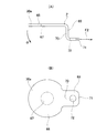
- the steering device transmits the rotation of the steering wheel 1 to the input shaft 3 of the steering gear unit 2, and pushes and pulls the pair of left and right tie rods 4 based on the rotation of the input shaft 3.
- a steering angle is given to the wheel.
- the steering device includes a steering shaft 5 that supports the steering wheel 1 at its rear end, and a cylindrical steering column 6 that rotatably supports the steering shaft 5 in an axially inserted state inside the steering shaft 5.
- the front end portion of the steering shaft 5 is connected to the rear end portion of the intermediate shaft 8 via a universal joint 7, and the front end portion of the intermediate shaft 8 is connected to the input shaft 3 via another universal joint 9.
- the front-rear direction, the width direction, and the up-down direction mean the front-rear direction, the width direction, and the up-down direction of the vehicle unless otherwise specified.
- the steering device can include a tilt mechanism for adjusting the vertical position of the steering wheel 1 and a telescopic mechanism for adjusting the front-rear position of the steering wheel 1.
- the gear housing 10 fixed to the front portion of the steering column 6 is supported with respect to the vehicle body 11 by a tilt shaft 12 arranged in the width direction so as to be able to swing and displace.
- a displacement bracket 13 is provided below the steering column 6, and a support bracket 14 is disposed at a position sandwiching the displacement bracket 13 from both sides in the width direction.
- the support bracket 14 has a vertical slot 15 extending in the vertical direction, and the displacement bracket 13 has a longitudinal slot 16 extending in the front-rear direction.
- the adjustment rod 17 is disposed so as to pass through the vertical slot 15 and the longitudinal slot 16 in the width direction.
- the steering shaft 5 and the steering column 6 have a telescopic structure.
- FIG. 25 shows a structure similar to that described in Japanese Patent Laid-Open No. 2015-214291.
- the steering column 6 includes an outer column 18 disposed on the rear side and an inner column 19 disposed on the front side, and the front portion of the outer column 18 and the rear portion of the inner column 19 are fitted so as to be capable of relative displacement in the axial direction.
- the total length is configured to be extendable.
- the outer column 18 includes a slit 20 at the front portion thereof, and the inner diameter of the front portion of the outer column 18 can be elastically expanded and contracted.
- the outer column 18 includes a pair of sandwiched plate portions 21 a and 21 b that constitute the displacement bracket 13 at a portion that sandwiches the slit 20 from both sides in the width direction.
- the pair of sandwiched plate portions 21a and 21b has longitudinally long holes 16a and 16b.
- the support bracket 14 includes a pair of support plate portions 22a and 22b, and the pair of support plate portions 22a and 22b includes vertically elongated holes 15a and 15b.
- the adjustment rod 17 is disposed so as to pass through the pair of vertical slots 15a and 15b and the pair of longitudinal slots 16a and 16b.
- the base of the adjusting lever 23 is fixed to one end of the adjusting rod 17 at a portion protruding from the outer surface of one of the pair of supporting plate portions 22a and 22b.
- a cam device 24 is disposed between the outer surface of one support plate 22 a and the base of the adjustment lever 23.
- the cam device 24 includes a drive side cam 25 and a driven side cam 26, and the width direction dimension can be enlarged or reduced based on the relative rotation of these cams.
- the driven cam 26 is provided with an engaging convex portion 27 on its inner surface, and the engaging convex portion 27 is only displaced along the vertical elongated hole 15a into the vertical elongated hole 15a of one support plate portion 22a. Can be engaged.
- the drive side cam 25 can be rotated together with the adjustment rod 17 by the adjustment lever 23.
- a nut 28 is screwed into a portion protruding from the outer surface of the other support plate portion 22 b of the pair of support plate portions 22 a and 22 b.
- a thrust bearing 29 and a pressing plate 30 are disposed between the outer surface of the other support plate portion 22b and the nut 28.
- the adjustment lever 23 After moving the steering wheel 1 to a desired position, the adjustment lever 23 is swung in the direction opposite to the predetermined direction. Thereby, the drive side cam 25 rotates in the locking direction, the dimension in the width direction of the cam device 24 is enlarged, and the interval between the inner surfaces of the pair of support plate portions 22a and 22b is reduced. As a result, the surface pressure of the contact portion between the inner side surfaces of the support plate portions 22a and 22b and the outer side surfaces of the sandwiched plate portions 21a and 21b increases, and at the same time, the inner diameter of the front portion of the outer column 18 is elastically reduced. The surface pressure of the contact portion between the front inner peripheral surface of the outer column 18 and the rear outer peripheral surface of the inner column 19 increases. In this clamped state, the up / down position and the front / rear position after adjustment of the steering wheel 1 are maintained.
- the steering device can include a spring 31.
- One end of the spring 31 is locked to the support bracket 14, and the other end of the spring 31 is in elastic contact with the lower surface of the pressing plate 30.
- the spring 31 applies an upward force to the other end portion of the adjustment rod 17 via the pressing plate 30 in a direction substantially along the extending direction of the vertical elongated hole 15b. For this reason, when the position of the steering wheel 1 is adjusted, the steering column 6 is prevented from tilting, and the vertical position of the steering wheel 1 can be adjusted with a light force.
- the width of the cam device 24 is reduced, and when the support bracket releases the clamping force that clamps the displacement bracket from both sides in the width direction, the adjustment lever 23 is vigorous. Oscillates well and may generate abnormal noise (metal contact sound).
- the drive-side cam 25 includes a drive-side cam surface 55 that is an uneven surface in the circumferential direction on the inner side surface (the lower side surface in FIG. 26).
- the drive-side cam surface 55 is a flat surface-like drive-side base surface 57 and a cross section that protrudes inward in the width direction (downward in FIG. 26) from a plurality of circumferentially equidistant positions on the drive-side base surface 57. It has a substantially trapezoidal drive side convex portion 58.
- the driven cam 26 includes a driven cam surface 62 that is a concavo-convex surface in the circumferential direction on the outer side surface (the upper side surface in FIG. 26).
- the driven cam surface 62 protrudes outward in the width direction (upward in FIG. 26) from a plurality of equally spaced circumferential positions of the driven side base bottom 63 and the driven base bottom 63 in the circumferential direction.
- the driven-side convex portion 64 having a substantially trapezoidal cross section.
- the driving cam surface 55 and the driven cam surface 62 come into contact with each other, and the tip surface of the driving convex portion 58 collides with the driven base surface 63 vigorously. Then, the leading end surface of the driven side convex portion 64 collides with the driving side base surface 57 vigorously. Furthermore, the driving side stopper surface 59 provided on the front side in the unlocking direction of the driving side convex portion 58 violently collides with the driven side stopper surface 66 provided on the rear side in the unlocking direction of the driven side convex portion 64. To do. As a result, abnormal noise based on the collision between metals is generated. In the illustrated example, the adjustment lever 23 is moved to the swing limit with the driving cam surface 55 and the driven cam surface 62 being in contact with each other, and the width direction dimension of the cam device 24 is the largest. Get smaller.
- An object of the present invention is to provide a steering device that can effectively prevent the above-described problem.
- the steering device of the present invention includes a steering column, a displacement bracket, a support bracket, an adjustment rod, a cam device, and an adjustment lever.
- the steering column is for rotatably supporting the steering shaft in an axial direction inside thereof, and has a cylindrical shape, is attached to a vehicle body or a member that can be fixed to the vehicle body, and has a width. It is arranged in the direction, and can be oscillated and displaced about a tilt shaft that supports the steering column or a member fixed to the steering column.
- the steering column can be composed of an inner column and an outer column that is disposed on the rear side of the inner column and is fitted to the inner column so as to be capable of relative displacement in the axial direction.
- the displacement bracket is provided in a part of the steering column and has a column side through-hole penetrating the displacement bracket in the width direction.
- the displacement bracket is provided in a part of the outer column, and the column side through hole extends in a front / rear direction elongated hole (telescopic adjustment length). Hole).
- the steering device of the present invention does not include a telescopic mechanism, it can be configured by a circular hole.
- the support bracket is provided on a mounting plate portion, a pair of support plate portions connected to the mounting plate portion and disposed on both sides in the width direction of the displacement bracket, and the pair of support plate portions. And a pair of vertically elongated slots (tilt adjusting slots).
- the adjusting rod is inserted in the width direction through the column side through hole and the pair of vertically elongated holes.
- the cam device includes a driving cam and a driven cam, and a portion of one end of the adjustment rod that protrudes from the outer surface of one of the support plate portions of the pair of support plate portions. Arranged around.
- the adjustment lever has a base fixed to the driving cam.
- the tension spring is arranged between the support bracket and the base of the adjustment lever.
- the adjusting rod can be rotated in synchronization with the driving cam in response to the swinging operation of the adjusting lever. Alternatively, it is possible to rotate only the drive side cam and not rotate the adjusting rod.
- the adjustment lever when the adjustment lever is swung in a direction to reduce the width direction dimension of the cam device, before the width direction dimension of the cam device is minimized, in other words, the adjustment lever is swung.
- both ends of the tension spring and the central axis of the adjusting rod are aligned on the same straight line.
- the drive cam can have one side surface in the width direction and the other side surface in the width direction.
- the driven-side cam can include one side surface in the width direction and the other side surface in the width direction facing the one side surface in the width direction of the driving side cam.
- the adjusting lever is swung in a direction to reduce the width direction dimension of the cam device, and the adjusting lever is provided on one side surface of the driving cam in a state where the swinging operation of the adjusting lever is stopped.
- the driving side cam surface and the driven side cam surface provided on the other side surface in the width direction of the driven side cam come into contact with each other. In other words, the swinging operation of the adjustment lever is stopped before the driving cam surface and the driven cam surface come into contact with each other.
- the drive-side cam surface can include a flat drive-side base surface and a plurality of drive-side convex portions protruding from a plurality of circumferential positions on the drive-side base surface toward one side in the width direction.
- the driven cam surface includes a flat driven bottom side surface and a plurality of driven side protrusions protruding from a plurality of circumferential directions on the driven side bottom surface toward the other side in the width direction. be able to.
- the adjustment lever is swung in a direction to reduce the width direction dimension of the cam device, and the front end surface of the driving-side convex portion and the driven-side base are stopped in a state where the swinging operation of the adjusting lever is stopped.
- a gap is formed between the front surface of the driven-side convex portion and the driving-side base surface.
- the steering device of the present invention it is effective that abnormal noise is generated based on a collision between the driving cam and the driven cam when the clamping force is released in order to adjust the position of the steering wheel. Can be prevented.
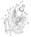
- FIG. 1 is a perspective view of the steering device of the first example of the embodiment as viewed from the adjustment lever side on the rear side and the upper side.
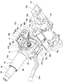
- FIG. 2 is a perspective view of the steering device of the first example of the embodiment as viewed from the rear side and the upper side from the side opposite to the adjustment lever.
- FIG. 3 is a perspective view of the steering device of the first example of the embodiment as viewed from the adjustment lever side on the front side and the upper side.
- FIG. 4 is a perspective view of the steering device of the first example of the embodiment as viewed from the adjustment lever side on the rear side and the lower side.
- FIG. 5 is a perspective view of the steering device of the first example of the embodiment as viewed from the side opposite to the adjustment lever on the rear side and the lower side.
- FIG. 1 is a perspective view of the steering device of the first example of the embodiment as viewed from the adjustment lever side on the rear side and the upper side.
- FIG. 2 is a perspective view of the steering device of the first example of the embodiment as
- FIG. 6 is a side view of the steering device of the first example of the embodiment as viewed from the adjustment lever side.
- FIG. 7 is a side view of the steering device of the first example of the embodiment as viewed from the side opposite to the adjustment lever.
- FIG. 8 is a plan view of the steering device of the first example of the embodiment.
- FIG. 9 is a bottom view of the steering device of the first example of the embodiment.
- FIG. 10 is a cross-sectional view taken along the line AA of FIG. 6 showing the steering device of the first example of the embodiment.
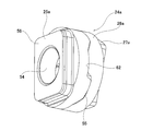
- FIG. 11 is a perspective view of a cam device incorporated in the steering device of the first example of the embodiment.
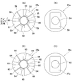
- FIG. 12 (A) to 12 (D) schematically show a driving side cam and a driven side cam of a cam device incorporated in the steering device of the first example of the embodiment
- FIG. 12B is a rear view of the driving cam
- FIG. 12C is a front view of the driven cam
- FIG. 12D is a rear view of the driven cam.
- 13A and 13B show a pressing plate incorporated in the steering device of the first example of the embodiment
- FIG. 13A is a plan view of the pressing plate
- FIG. FIG. 3 is a front view of the pressing plate.
- 14 is a cross-sectional view taken along the line BB in FIG. FIG. 15A and FIG.
- FIG. 15B are explanatory diagrams of the relationship between the swinging position of the adjustment lever and the engagement state of the cam device with respect to the steering device of the first example of the embodiment.
- A) shows (a) the swinging position of the adjusting lever in the locked state, and (b) the engaged state of the driving cam and the driven cam in the locked state.
- A) The swinging position of the adjusting lever in the unlocked state, and (b) the engaged state of the driving side cam and the driven side cam in the unlocked state.
- FIG. 16 is a partially omitted enlarged view of a portion corresponding to the left and right intermediate portion of FIG. 6 showing a second example of the embodiment.
- FIG. 17 is a partial cross-sectional enlarged view of a portion corresponding to the left and right intermediate portion of FIG.
- FIG. 6 showing a second example of the embodiment.
- 18 is a cross-sectional view taken along the line DD of FIG. 19A and 19B show a tension spring incorporated in the steering device of the third example of the embodiment
- FIG. 19A is a perspective view of the tension spring
- FIG. FIG. 3 is an end view of a tension spring.
- FIG. 20 is a partially omitted view showing a state in which the tension spring is locked to the base portion of the adjusting lever at the swinging position of the adjusting lever in the unlocked state with respect to the steering device of the fourth example of the embodiment. .
- FIG. 21 is a partially omitted view showing a state in which the tension spring is locked to the base portion of the adjustment lever at the swinging position of the adjustment lever in the unlocked state with respect to the steering device of the fifth example of the embodiment.
- . 22 (A) and 22 (B) show a pressing plate incorporated in the steering device of the sixth example of the embodiment, and FIG. 22 (A) is a plan view of the pressing plate, FIG. 22 (B).
- FIG. 3 is a front view of the pressing plate.
- FIG. 23 is a schematic diagram of an example of a conventional steering apparatus to which the present invention can be applied.
- FIG. 24 is a partial side view of an example of a conventional steering wheel position adjusting device to which the present invention can be applied.
- FIG. 25 is a cross-sectional view taken along the line CC of FIG.
- FIG. 26 is a schematic cross-sectional view for explaining the change in the contact state between the cam surfaces when the cam device is switched from the locked state to the unlocked state with respect to the conventional structure.
- FIGS. 1 to 10 and FIG. 15 (A) show a state where the adjustment lever 23a is swung to a locked position where the position of the steering wheel 1 (see FIG. 23) is held.
- FIG. 15B shows a state where the adjusting lever 23a is swung to an unlock position where the position of the steering wheel 1 can be adjusted.
- the steering device of this example is supported by a steering shaft 5a that supports the steering wheel 1 at its rear end, and a vehicle body 11 (see FIG. 23), and a plurality of steering shafts 5a are inserted in the axial direction inside the steering shaft 5a. And a cylindrical steering column 6a that is rotatably supported via a rolling bearing.
- a gear housing 10a constituting an electric assist device is fixed to the front end of the steering column 6a.
- the gear housing 10a is supported by the lower bracket 32 that can be fixed to the vehicle body 11 so as to be capable of swinging and shifting around the tilt shaft 12a disposed in the width direction.
- An electric motor (not shown) is supported on the gear housing 10a, and the output torque of the electric motor is applied to the steering shaft 5a via a speed reduction mechanism disposed inside the gear housing 10a. As a result, the force required to operate the steering wheel 1 can be reduced.
- the steering device of this example includes a telescopic mechanism for adjusting the front-rear position of the steering wheel 1 and a tilt mechanism for adjusting the vertical position of the steering wheel 1 according to the physique and driving posture of the driver.
- the steering column 6a is fitted to the rear part of the inner column 19a arranged on the front side (lower side) and the front part of the outer column 18a arranged on the rear side (upper side) so as to allow relative displacement in the axial direction.
- the outer column 18a is supported so as to be movable in the front-rear direction with respect to the support bracket 14a.
- the steering shaft 5a has a structure in which an inner shaft 33 and an outer shaft 34 are combined so that torque can be transmitted and expanded and contracted by spline engagement or the like.
- Such a structure constitutes a telescopic mechanism.
- the steering column can be configured by a single cylindrical member.
- the steering column 6a and the gear housing 10a are supported so as to be able to swing and displace around the tilt shaft 12a with respect to the vehicle body 11, and the outer column 18a is supported so as to be movable in the vertical direction with respect to the support bracket 14a.
- a tilt mechanism is configured.
- the outer column 18a is made of a light alloy such as an aluminum-based alloy or a magnesium-based alloy, and is a sandwiched portion 35 disposed in the front half, and is made of an iron-based alloy such as carbon steel, and is disposed in the latter half. And a cylindrical portion 36 coupled to the shaft 35 in the axial direction.
- the sandwiched portion 35 is supported so as to be movable in the front-rear direction and the up-down direction with respect to the support bracket 14a.
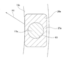
- the sandwiched portion 35 of the outer column 18a includes a column fitting portion 37 in its upper half and a displacement bracket 13a in its lower half. As shown in FIG.
- the column fitting portion 37 includes a slit 20a that is fitted on the rear portion of the inner column 19a and extends in the axial direction at the lower end portion thereof.
- the displacement bracket 13a includes a pair of sandwiched plate portions 21c and 21d disposed on both sides in the width direction of the slit 20a below the column fitting portion 37. The lower ends of the pair of sandwiched plate portions 21c and 21d are connected in the width direction.
- the front half of the outer column 18a corresponds to a part of the steering column 6a.
- the pair of sandwiched plate portions 21c, 21d includes column-side through holes penetrating in the width direction, and includes longitudinal long holes (telescopic adjustment long holes) 16c, 16d extending in the front-rear direction.
- the longitudinal holes 16c and 16d are mounted on the inner sides of the lower holes 38a and 38b formed in the sandwiched plate portions 21c and 21d and the outer half in the width direction of the lower holes 38a and 38b.
- the sleeves 39a and 39b are made of synthetic resin and are formed of inner surfaces.
- the sleeves 39a and 39b are made of a synthetic resin excellent in slidability such as a polyamide resin, a polyacetal resin, and a polytetrafluoroethylene resin.
- the column-side through hole can be configured by a simple circular hole.
- the support bracket 14a is made of a metal plate having sufficient rigidity, such as steel or an aluminum alloy, and is connected to the mounting plate portion 40 and the mounting plate portion 40, and is disposed on both sides in the width direction of the displacement bracket 13a.
- the support plate portions 22c and 22d and the pair of support plate portions 22c and 22d have a pair of vertical long holes (tilt adjustment long holes) 15c and 15d extending in the vertical direction.
- the mounting plate part 40 is locked to the locking capsule 41 supported and fixed to the vehicle body so as to be able to be detached forward.
- the mounting plate portion 40 is normally supported with respect to the vehicle body 11 via the locking capsule 41, but in the event of a collision accident, the mounting plate portion 40 is detached forward from the locking capsule 41 based on the impact of the secondary collision, A forward displacement of the outer column 18a is allowed.
- the mounting plate portion 40 includes a bridge portion 42 disposed in the center portion in the width direction and a pair of side plate portions 43a and 43b disposed on both sides in the width direction.
- the bridge portion 42 has an inverted U-shaped cross section and is disposed above the sandwiched portion 35 of the outer column 18a.
- the bridge portion 42 includes a plurality of (three in the illustrated example) ribs 44 arranged in a state of being separated in the front-rear direction, and the rigidity of the bridge portion 42 is ensured.
- Each of the pair of side plate portions 43a and 43b has a flat plate shape and is provided with a locking notch for opening the locking capsule 41 and opening at the rear end edge thereof.
- Each of the pair of side plate portions 43a and 43b includes substantially L-shaped locking arm portions 45a and 45b at the width direction inner end portion of the front end portion thereof.
- the locking arm portions 45a and 45b are bent at a substantially right angle downward from the widthwise inner ends of the front end portions of the pair of side plate portions 43a and 43b and project forward from the lower end portions thereof.
- Have The shape of the locking arm portions 45a and 45b and the formation position thereof are preferably symmetrical with respect to the width direction.
- the upper ends of the pair of support plate portions 22c and 22d are fixed to both ends in the width direction of the lower surface of the bridge portion 42 by welding.
- the pair of support plate portions 22c and 22d are disposed substantially parallel to each other on both sides in the width direction of the sandwiched portion 35 of the outer column 18a.
- the pair of support plate portions 22c and 22d includes a pair of vertical elongated holes 15c and 15d extending in the vertical direction in a partial arc shape with the tilt shaft 12a as the center.
- the pair of support plate portions 22c and 22d includes reinforcing protrusions 46a and 46b extending in the vertical direction at the front end portions thereof.
- the upper end portions of the reinforcing protrusions 46 a and 46 b are not continuous with the bridge portion 42.
- the tension springs 73a and 73b are arranged on both outer sides in the width direction of the pair of support plate portions 22c and 22d, reinforcement is performed in order to suppress the protruding amount to the outer side in the width direction while securing the section modulus.
- the ridges 46a, 46b have a circular arc shape in which the front end portion is folded inward in the width direction.
- the pair of support plate portions 22c and 22d includes bending plate portions 47a and 47b that extend in the vertical direction and bend substantially perpendicularly toward the outer side in the width direction at the rear end portions.
- the reinforcing protrusions 46a and 46 and the bent plate portions 47a and 47b are provided to increase the bending rigidity (torsional strength) of the support plate portions 22c and 22d.
- the shape of the vertically elongated hole is not limited to the partial arc shape with the tilt axis as the center, and alternatively, a linear shape that extends in the backward direction as it goes upward can be adopted.
- the adjusting rod 17a is disposed so as to pass through the pair of longitudinal elongated holes 16c, 16d and the pair of vertically elongated holes 15c, 15d in the width direction.
- the adjustment rod 17a includes a head portion 48 at one end portion and a male screw portion 49 at the other end portion.
- a disc spring 50, an adjusting lever 23a, and a cam device 24a are arranged between the outer side surfaces in order from the outside in the width direction.
- a nut 28a and a thrust bearing 29a are sequentially arranged from the outer side in the width direction around a portion protruding from the outer surface of the other support plate portion 22d of the pair of support plate portions 22c and 22d.
- a pressing plate 30a is arranged.
- the nut 28a is screwed into a male screw portion 49 at the other end of the adjustment rod 17a.
- the heads 48 and nuts 28a arranged at both ends of the adjusting rod 17a cannot be displaced relative to each other in the axial direction of the adjusting rod 17a. It functions as a displacement restricting portion that prevents displacement outward in the direction.
- the adjusting lever 23a and the cam device 24a constitute an expansion / contraction mechanism.
- the distance between the driven cam 26a and the pressing plate 30a and the distance between the inner surfaces of the pair of support plate portions 22c and 22d. Can be scaled.
- the magnitude of the clamping force with which the support bracket 14a clamps the displacement bracket 13a from both sides in the width direction can be adjusted.
- the adjusting lever 23a is a member for swinging when the driver adjusts the position of the steering wheel 1.
- the adjustment lever 23a is made of a metal plate such as a steel plate or a stainless steel plate, and has a long shape bent in a substantially crank shape. In this example, the adjustment lever 23a is disposed so as to extend rearward (driver's seat side) and downward as it goes toward the distal end side.
- the adjustment lever 23a includes a flat plate-like base portion 51 at a front end side portion (upper end side portion) thereof.
- the base 51 includes a substantially rectangular mounting hole 52 that penetrates in the plate thickness direction.
- the base 51 includes a circular spring locking hole 53 in a portion located in front of the mounting hole 52.
- the adjustment lever 23a is fixed to the driving cam 25a so as not to be relatively rotatable by using the mounting hole 52. For this reason, the driving cam 25a can rotate relative to the driven cam 26a by the swinging operation of the adjusting lever 23a.
- the cam device 24a in the state shown in FIGS. 15A and 15A in which the adjustment lever 23a is swung upward, the cam device 24a is in a locked state, and the adjustment lever 23a is swung downward in FIG. 15B. In the state shown in (a), the cam device 24a is unlocked.
- the cam device 24a is composed of a combination of a driving side cam 25a and a driven side cam 26a.
- the driving side cam 25a is arranged on the outer side in the width direction
- the driven side cam 26a is arranged on the inner side in the width direction.
- the driving side cam 25a may be disposed on the inner side in the width direction
- the driven side cam may be disposed on the outer side in the width direction. In this case, the direction of the width direction in the following description is reversed.
- the drive side cam 25a is made of sintered metal, has an annular plate shape as a whole, and includes a center hole 54 through which the adjustment rod 17a is inserted.
- the driving cam 25a has an inner surface that is one side surface in the width direction and an outer surface that is the other side surface in the width direction.
- the drive-side cam 25a includes a drive-side cam surface 55 that is an uneven surface in the circumferential direction on the inner surface.
- the driving cam 25a is provided with a substantially rectangular fitting convex portion 56 in front view for fitting and fixing the base portion 51 of the adjusting lever 23a on the outer surface.
- the drive-side cam surface 55 has a flat-side drive-side base surface 57 and a plurality of circumferentially equidistant positions (four locations in the illustrated example) on the drive-side base surface 57 within the width direction corresponding to one side in the width direction. And a drive-side convex portion 58 having a substantially trapezoidal cross section.
- a drive-side stopper surface 59 is provided on the front side in the unlocking direction, which is the rotation direction of the drive-side cam 25a when switching to the unlocked state, on both sides in the circumferential direction of the drive-side convex portion 58, and the rear side thereof.
- a driving side guide slope 60 is provided on the side.
- the drive-side guide slope 60 and the drive-side stopper face 59 have opposite inclination directions with respect to the circumferential direction, and the drive-side stopper face 59 has a greater inclination angle with respect to the drive-side base face 57. Greater than 60. In this example, the drive side stopper surface 59 is not practically used.
- the drive side cam 25a is fixed to the base 51 of the adjustment lever 23a and adjusted.
- the adjustment lever 23a and the adjustment rod 17a engage with each other so as not to rotate relative to each other by, for example, an uneven fitting (not shown), so that the drive cam 25a can rotate in synchronization with the adjustment rod 17a.
- the driven cam 26a is made of sintered metal, has an annular plate shape as a whole, and is provided with a central hole 61 through which the adjusting rod 17a is inserted, like the driving cam 25a.
- the driven cam 26a has an inner surface that is one side surface in the width direction and an outer surface that is the other side surface in the width direction.
- the driven cam 26a includes a driven cam surface 62 that is an uneven surface in the circumferential direction on the outer surface.
- the driven cam 26a is provided with a substantially rectangular plate-like engagement convex portion 27a protruding inward in the width direction on the inner side surface.
- the driven-side cam surface 62 is directed to a widthwise outer side corresponding to the other side in the width direction from a plurality of equally spaced circumferential positions of the driven-side base bottom surface 63 and the driven-side base bottom surface 63. It has a substantially trapezoidal cross section and has the same number of driven side convex portions 64 as the driving side convex portions 58.
- a driven side guide slope 65 is provided on the front side in the unlocking direction of both sides in the circumferential direction of the driven side convex portion 64, and a driven side stopper surface 66 is provided on the rear side thereof. Yes.
- the driven-side guide slope 65 and the driven-side stopper surface 66 are opposite in the inclination direction with respect to the circumferential direction, and the inclination angle with respect to the driven-side base surface 63 is larger in the driven-side stopper surface 66. It is larger than the driven side guide slope 65. In this example, the driven-side stopper surface 66 is not substantially used.
- the driven cam 26a is fitted on the adjusting rod 17a so as to be capable of relative rotation with respect to the adjusting rod 17a and relative displacement in the axial direction of the adjusting rod 17a.
- the engaging convex part 27a engages with the up-down direction long hole 15c of one support plate part 22c so that only the displacement along the up-down direction long hole 15c is possible. For this reason, the driven cam 26a can be moved up and down along the up-and-down direction long hole 15c, but exists between the front-and-rear side edge of the up-and-down direction long hole 15c and the front-and-rear side surface of the engaging convex part 27a. Except for a slight rotation caused by the gap, it does not rotate greatly.
- the adjustment lever 23a When adjusting the position of the steering wheel 1, the adjustment lever 23a is swung downward from the lock position shown in FIGS. 15A and 15A to the unlock position shown in FIGS. Accordingly, as shown in FIGS. 15A and 15B, the driving side cam 25a rotates in the unlocking direction, and as shown in FIGS. 15B and 15B, the driving side convex portion 58 and the driven side are driven. It will be in the unlocking state by which the side convex part 64 was alternately arrange
- the surface pressure of the contact portion between the inner surface of the support plate portions 22c and 22d and the outer surface of the sandwiched plate portions 21c and 21d is reduced or lost, and at the same time, the inner diameter of the column fitting portion 37 of the outer column 18a is reduced. It expands elastically, and the surface pressure of the contact portion between the inner peripheral surface of the column fitting portion 37 and the rear outer peripheral surface of the inner column 19a decreases.
- the vertical position and the front / rear position of the steering wheel 1 can be adjusted within a range in which the adjustment rod 17a can move inside the pair of vertical slots 15c, 15d and the pair of longitudinal slots 16c, 16d. It becomes possible.
- the adjustment lever 23a is swung upward from the state shown in FIGS. Rotate 25a in the locking direction.
- FIGS. 15A and 15B the leading end surface of the driving-side convex portion 58 and the leading end surface of the driven-side convex portion 64 abut each other (locked state), and the width direction dimension of the cam device 24a. And the distance between the driven cam 26a and the pressing plate 30a (the distance between the inner surfaces of the pair of support plate portions 22c and 22d) is reduced.
- the disc spring 50 is made of a metal such as carbon steel, carbon tool steel, or spring steel, has an annular shape, is externally fitted to a portion near one end of the adjustment rod 17a, and is an inner surface of the head 48 of the adjustment rod 17a. And the outer surface of the base 51 of the adjusting lever 23a.
- the disc spring 50 imparts elasticity in a direction away from each other to the inner surface of the head 48 and the outer surface of the base 51. For this reason, even when the clamping force is released in order to adjust the position of the steering wheel 1, the cam device 24a has a width direction between the inner surface of the head 48 and the outer surface of the one support plate portion 22c.
- the occurrence of rattling can be suppressed, and the occurrence of rattling in the width direction between the inner surface of the nut 28a and the outer surface of the other support plate portion 22d can be suppressed in the thrust bearing 29a and the pressing plate 30a. it can.
- the disc spring 50 can be omitted because the cam device 24a and the thrust bearing 29a can be prevented from wobbling in the width direction by using the moment acting on the pressing plate 30a.
- the pressing plate 30a is made of a metal plate such as a cold rolled steel plate (SPCC) or a hot rolled steel plate (SPHC), and has a crank shape as a whole.
- the pressing plate 30a is fitted on a portion closer to the other end of the adjusting rod 17a so as to be capable of relative rotation with respect to the adjusting rod 17a and relative displacement in the axial direction of the adjusting rod 17a.
- the pressing plate 30a has an insertion hole 67 through which the adjustment rod 17a is inserted, and is arranged at one place in the circumferential direction of the annular plate body 68 that is externally fitted to the adjustment rod 17a and the outer peripheral edge of the plate body 68.
- the substantially L-shaped locking plate part 69 is provided.
- the base half portion 70 of the locking plate portion 69 has a flat plate shape and extends from the outer peripheral edge of the plate main body 68 toward the outside in the width direction (the axial direction of the plate main body 68). Is flat and extends from the outer end (front end) in the width direction of the base half 70 toward the opposite side of the plate body 68 so as to be bent at a substantially right angle.
- the plate body 68 is disposed between the outer surface of the other support plate portion 22d and the inner surface of the thrust bearing 29a.
- the front half 71 of the locking plate 69 has a circular spring locking hole 72.
- the distance from the rotation center (center axis) of the adjustment rod 17a to the spring engagement hole 72 is the distance from the rotation center of the adjustment rod 17a to the spring engagement hole 53 provided in the base 51 of the adjustment lever 23a.
- the plate main body 68 and the front half 71 of the locking plate portion 69 are arranged in parallel to each other, and the base half 70 of the locking plate 69 is in relation to the plate main body 68 and the front half 71 of the locking plate 69. Arranged at right angles.
- the pressing plate 30a corresponds to the locked portion.
- the thrust bearing 29a has a pair of ring-shaped race rings and a plurality of needles arranged radially between the pair of race rings.
- the thrust bearing 29a supports a thrust load acting on the pressing plate 30a from the nut 28a, and enables the nut 28a to reciprocate.
- a pair of tension springs 73a and 73b are disposed on both outer sides in the width direction of the pair of support plate portions 22c and 22d of the support bracket 14a.
- the pair of tension springs 73a and 73b are made of spring steel such as stainless steel and piano wire, have the same spring constant, and have the same length in the free state. Consists of. As shown in FIG.
- the center axes O a and O b of the pair of tension springs 73a and 73b are directed outward in the width direction toward the front with respect to the center axis O 6 of the steering column 6a. It is arranged with a slight inclination in the direction of (separating) several degrees (for example, 1 degree to 5 degrees) or arranged in parallel. As shown in FIGS. 6 and 7, the central axes O a and O b of the pair of tension springs 73a and 73b are several tens of degrees in the upward direction toward the front (for example, 30 to 50 degrees). It is inclined to some extent. In this example, the inclination angle inclined in the width direction with respect to the central axis O 6 of the steering column 6a is substantially the same in the one tension spring 73a and the other tension spring 73b.
- One tension spring 73a of the pair of tension springs 73a and 73b includes a U-shaped hook portion 74a disposed at one end, a U-shaped hook portion 74b disposed at the other end, and an intermediate And a coil part 77a arranged in the part.
- the hook portion 74a is locked to the locking arm portion 45a of the one side plate portion 43a from the outside in the width direction.
- the hook portion 74b is locked from the inner side in the width direction to the spring locking hole 53 of the base 51 of the adjustment lever 23a.
- one tension spring 73a is arrange
- One tension spring 73a applies a force F1 directed obliquely upward to the base 51 of the adjusting lever 23a.
- the front side surface of the engaging convex portion 27a of the driven cam 26a is ,
- One of the support plate portions 22c is elastically pressed against the front edge of the up-down direction long hole 15c.
- the other tension spring 73b of the pair of tension springs 73a and 73b includes a U-shaped hook portion 75a disposed at one end, a U-shaped hook portion 75b disposed at the other end, And a coil part 77b arranged in the part.
- the hook portion 75a is locked to the locking arm portion 45b of the other side plate portion 43b from the outside in the width direction.
- the hook portion 75b is locked from the inner side in the width direction to the spring locking hole 72 of the front half portion 71 of the locking plate portion 69 of the pressing plate 30a.
- the other tension spring 73b is arranged so as to be bridged between the other side plate portion 43b and the pressing plate 30a.
- the other tension spring 73b applies a force F2 that is directed obliquely upward to the pressing plate 30a.
- a pair of tension springs 73a and 73b disposed on both outer sides in the width direction of the support bracket 14a are applied to the both ends of the adjustment rod 17a in an obliquely upward direction. . Therefore, an upward force is applied to the outer column 18a, so that the steering column 6a can be prevented from tilting when the position of the steering wheel 1 is adjusted (unclamped). Adjustment can be performed with a light force.
- the adjustment lever 23a is swung in a direction to reduce the width direction dimension of the cam device 24a, and the adjustment lever 23a is moved to the unlock position, that is, the adjustment lever 23a is rotated downward.
- the total length L1 of the inclination angle ⁇ 1 and one tension spring 73a with respect to the center axis O 6 of the steering column 6a of one of the tension springs 73a shown in FIG.
- the pressing plate 30a is pressed against the outer surface of the other support plate portion 22c and the inner surface of the thrust bearing 29a based on the pulling force of the other tension spring 73a. Therefore, when the adjustment rod 17a is moved in the vertical direction. However, the rotational phase hardly changes. For this reason, when the adjusting lever 23a is moved to the unlocked position regardless of the vertical position of the adjusting rod 17a, the inclination angle with respect to the steering column 6a and the total length thereof are changed between the one tension spring 73a and the other tension spring 73b. Are the same as each other.
- the direction of action of the force of the pair of tension springs 73a and 73b is the tilt shaft 12a and the adjustment rod 17a. It faces upward by a predetermined angle (for example, about 10 to 30 degrees) from the direction of the virtual straight line M (see FIG. 7) orthogonal to the direction.
- a predetermined angle for example, about 10 to 30 degrees
- the angle between the direction of action of the central axis O 6 and the tension spring 73a, 73b of the force of the steering column 6a is greater than the angle between the center axis O 6 of the steering column 6a and the virtual straight line M.
- a pair of tension springs are located with respect to the central axis of the steering column with respect to the base of the adjusting lever and the locked portion.
- the structure, shape, and length (attachment of both ends) are not limited to the above-mentioned preferred examples as long as the same magnitude of force can be applied in the direction of action directed diagonally forward and upward by the same angle. It is also possible to adopt a configuration in which the position) differs between one tension spring and the other tension spring.
- the force applied from one tension spring 73a to the base 51 of the adjusting lever 23a acts as a drag (brake) that suppresses the rotation of the drive cam 25a.
- a gap 76a is formed between the distal end surface of the driving-side convex portion 58 and the driven-side base surface 63, and the driven side A gap 76 b is formed between the distal end surface of the side convex portion 64 and the driving side base surface 57, and a gap 76 c is formed between the driving side stopper surface 59 and the driven side stopper surface 66.
- the steering device of the present example when the adjustment lever 23a is swung downward from the clamp position, the leading end surface of the driving-side convex portion 58, the driven-side base surface 63, and the leading end surface of the driven-side convex portion 64 It is possible to prevent the generation of abnormal noise (metal contact sound) due to the violent collision between the driving side base surface 57 and the driving side stopper surface 59 and the driven side stopper surface 66. Further, as shown in FIGS. 15B and 15B, the clearance 76a between the front end surface of the driving side convex portion 58 and the driven side base surface 63, and the front end surface of the driven side convex portion 64 and driving.
- abnormal noise metal contact sound
- the width direction dimension of the cam device 24a in the unlocked state can be increased by the gap 76b between the side base bottom surface 57 and the side base bottom surface 57. For this reason, it is possible to prevent the cam device 24a from rattling in the width direction between the inner surface of the head 48 and the outer surface of the one support plate portion 22c, and the inner surface of the nut 28a and the other support are supported. It is possible to suppress the occurrence of rattling in the width direction between the thrust bearing 29a and the pressing plate 30a with the outer surface of the plate portion 22d. Further, since the rotation of the drive cam 25a is braked by the one tension spring 73a, the adjustment lever 23a is vibrated vigorously, and a part of the adjustment lever 23a is prevented from colliding with the finger of the passenger.
- the width direction dimension of the cam device 24a in the unlocked state can be increased by the gap 76b between the side base bottom surface 57 and the side base bottom surface 57. For this reason, it is possible to prevent the cam device 24
- the force applied from the other tension spring 73b to the pressing plate 30a causes a moment to act on the pressing plate 30a.
- the hook portion 75b of the other tension spring 73b is the first half of the locking plate portion 69 disposed at a position that is disengaged (offset) in the width direction with respect to the plate body 68 that is externally fitted to the adjustment rod 17a. Locked to the portion 71.
- the pressing plate 30a is provided with a bent portion between the plate main body 68 and the base half portion 70 of the locking plate portion 69 based on the force F2 acting from the other tension spring 73b. And a moment in the direction of the arrow ⁇ acts around an imaginary straight line Z extending in the extending direction of the bent portion.
- the plate main body 68 applies forces in directions away from each other to the outer surface of the other support plate portion 22d and the inner surface of the thrust bearing 29a. Therefore, similarly to the disc spring 50, even when the clamping force is released, the cam device 24a has a width between the inner surface of the head 48 that is the displacement restricting portion and the outer surface of the one support plate portion 22c. It is possible to suppress the occurrence of rattling in the direction, and it is possible to suppress the occurrence of rattling in the width direction of the thrust bearing 29a between the inner surface of the nut 28a serving as a displacement restricting portion and the outer surface of the plate body 68. .
- a pair of tension springs 73a and 73b are disposed on both outer sides in the width direction of the pair of support plate portions 22c and 22d of the support bracket 14a, and the base 51 of the adjustment lever 23a disposed at both ends of the adjustment rod 17a. And the force which faced the diagonally front upper direction is respectively provided with respect to the press plate 30a.
- the direction in which the force is applied by the pair of tension springs 73a and 73b is not upward along the extension direction of the pair of vertical elongated holes 15c and 15d, but is directed toward the diagonally upper front.
- the component force is kept small.
- the direction of action of the force of the pair of tension springs 73a and 73b is The push-up force is prevented from becoming too low by facing upward by a predetermined angle from the direction of the virtual straight line M perpendicular to the center axis of the tilt shaft 12a and the center axis of the adjustment rod 17a.
- the pair of tension springs 73a and 73b causes the base 51 of the adjustment lever 23a and the pressing plate 30a to face each other in the same direction. That power is given. For this reason, when the position of the steering wheel 1 is adjusted, the posture of the adjustment rod 17a can be stabilized, and the adjustment rod 17a can be prevented from being tilted up and down.
- the direction of the force applied by the pair of tension springs 73a and 73b is not the upper direction along the extension direction of the pair of vertical elongated holes 15c and 15d, but the direction facing diagonally forward and upward.
- the upward component force can be kept small, and a frictional force can be generated between the front side surface of the engaging convex portion 27a and the front side edge of the vertically elongated hole 15c. For this reason, when the clamping force is released, the position of the steering wheel 1 can be kept at the position where the clamping force is released. Therefore, it is possible to realize a structure that does not cause a sudden jump or a sudden drop in the steering wheel 1 when the clamping force that has been conventionally required for the steering device is released.
- component forces directed outward in the width direction can be applied to the base 51 of the adjustment lever 23a and the pressing plate 30a. Also from this surface, it is possible to prevent the cam device 24a and the thrust bearing 29a from rattling in the width direction when the clamping force is released.
- the drive cam 25a tends to rotate vigorously.
- the driven cam 26a also tends to rotate around the adjustment rod 17a based on the concave and convex engagement between the driving cam surface 55 and the driven cam surface 62.
- the front side surface of the engagement convex portion 27a of the driven cam 26a is elastically pressed against the front edge of the vertical slot 15c by the elasticity of the tension spring 73a. It is possible to effectively prevent the cam 26a from rotating. For this reason, it is possible to prevent abnormal noise (metal contact sound) from being generated when the front and rear side surfaces of the engaging convex portion 27a and the front and rear side edges of the vertical elongated holes 15c collide with force.
- the steering wheel 1 When adjusting the front-rear position of the steering wheel 1, the steering wheel 1 is moved forward as much as possible, and the adjustment rod 17a is moved to the pair of front and rear direction long holes 16c, 16d and the pair of up and down direction long holes 15c. Also, when sandwiched between the front side edge of 15d, the front side surface of the engagement convex portion 27a is in contact with the front side edge of the vertical elongated hole 15c in advance, so that the front side surface of the engagement convex portion 27a is It is also possible to prevent a collision sound from being generated due to a violent collision with the front side edge of the directional elongated hole 15c.
- the present invention is applied to a steering apparatus including both a tilt mechanism and a telescopic mechanism, but the present invention can also be applied to a steering apparatus including only a tilt mechanism.
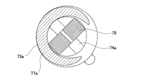
- a pair of tension springs 73a is used to prevent noise from being generated from the pair of tension springs 73a and 73b when the vertical position of the steering wheel 1 is adjusted or when the adjustment lever 23a is swung.
- 73b includes a damper member 78 disposed inside the coil portions 77a and 77b.
- the damper member 78 is made of an elastic material such as rubber or synthetic resin, and has an annular shape and a substantially rectangular cross-sectional shape as a whole in a free state.
- the damper member 78 is disposed inside the coil portions 77a and 77b in a state where the damper member 78 is deformed. Specifically, in a state where the portions of the damper member 78 located on the opposite sides in the diametrical direction are crushed so as to be close to each other (folded), and the entire damper member 78 is deformed into a linear shape (plate shape), The damper member 78 is inserted so as to be pushed into the coil portions 77a and 77b. In a state where the damper member 78 is disposed inside the coil portions 77a and 77b, the outer peripheral surface of the damper member 78 elastically contacts the inner peripheral surfaces of the coil portions 77a and 77b.
- the damper member 78 moves in the axial direction of the coil portions 77a and 77b.
- the length (folded diameter) of the damper member 78 in the coil portions 77a and 77b is regulated so as not to fall off from the inside of 77b.
- the upper end portion of the damper member 78 is in contact with the lower surfaces of the locking arm portions 45a and 45b.
- the length (engagement allowance) of the damper member 78 existing inside the coil portions 77a and 77b is sufficiently larger than, for example, the distance from the upper end surface of the coil portions 77a and 77b to the lower surfaces of the locking arm portions 45a and 45b. Secured to be longer.
- the lower end portion of the damper member 78 is the base 51 of the adjusting lever 23a and the locking plate portion 69 of the pressing plate 30a (FIGS. 7 and 7).
- the damper member 78 is disposed so that the damper member 78 disposed inside the coil portions 77a and 77b is not damaged by the attachment jig of the tension springs 73a and 73b during the attaching operation of the tension springs 73a and 73b. Length, in particular, the amount of protrusion from the coil portions 77a and 77b is restricted.
- the hook portion 75b (see FIG. 7) of the tension spring 73b is connected to the spring locking hole 72 of the pressing plate 30a.
- the amount of movement along the inner periphery of the is small.
- the damper member 78 may be arranged only inside the coil part 77a constituting one tension spring 73a and not arranged inside the coil part 77b constituting the other tension spring 73b.
- Other configurations and operational effects of the second example of the embodiment are the same as those of the first example of the embodiment.
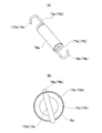
- a damper member 78a is disposed outside the coil portions 77a and 77b constituting the tension springs 73a and 73b.
- the damper member 78a is made of an elastic material such as rubber or synthetic resin, and has a cylindrical shape having an inner diameter slightly smaller than the outer diameter of the coil portions 77a and 77b in a free state.
- the damper member 78a is fitted on the outside of the coil portions 77a and 77b in a state where the inner diameter is slightly expanded elastically. In a state where the damper member 78a is disposed outside the coil portions 77a and 77b, the inner peripheral surface of the damper member 78a elastically contacts the outer peripheral surface of the coil portions 77a and 77b.
- the damper member 78a since the damper member 78a can be visually recognized from the outside, forgetting to attach the damper member 78a can be prevented.
- the damper member 78a is externally fitted to the coil portions 77a and 77b, and the hook portions 74a, 74b, 75a, and 75b existing on both sides of the coil portions 77a and 77b are the locking arm portions 45a and 45b, the adjustment lever 23a, and Since it is each latched by the press plate 30a, it can prevent effectively that the damper member 78a falls off.
- Other configurations and operational effects of the third example of the embodiment are the same as those of the first and second examples of the embodiment.
- the spring locking hole 53a is not a simple circular hole, but has a substantially triangular opening shape (which is a triangular hole) disposed on the front side (left side in FIG. 20), and a rear side ( It has a substantially tear-shaped opening shape in combination with a large-diameter hole portion 80 having a substantially semicircular opening shape arranged on the right side of FIG.
- the guide hole 79 has a pair of linear guide sides 81a and 81b that are inclined toward each other toward the front side, and a partially arcuate connection portion that connects the front ends of the pair of guide sides 81a and 81b. 82.
- the pair of guide sides 81 a and 81 b are line symmetric with respect to an imaginary straight line N that is orthogonal to the central axis O 17 of the adjustment rod 17 a and passes through the central portion in the circumferential direction of the connecting portion 82.
- the center O 80 of the large-diameter hole 80 is located on the virtual straight line N.
- the inner diameter d 80 of the large diameter hole portion 80 is sufficiently larger than the diameter D 74 of the hook portion 74b of the tension spring 73a (d 80> D 74) .
- the curvature radius of the connecting portion 82 is smaller than one half of the wire diameter D 74 of the hook portion 74b.
- the size of the included angle ⁇ 3 between the pair of guide sides 81a and 81b is determined in consideration of the wire diameter D 74 of the hook portion 74b, the shape of the base portion 51, and the like, for example, in the range of 30 degrees to 90 degrees.
- the angle is preferably set in the range of 45 to 75 degrees. In the illustrated example, the included angle ⁇ 3 is 60 degrees.
- the hook portion 74b is a pair of guide sides 81a and 81b that are in a direction approaching the connecting portion 82 by the elastic restoring force exerted by the coil portion 77a. It is pulled in the direction that the interval of becomes smaller.
- the hook portion 74b is elastically pressed between the pair of guide sides 81a and 81b (bite like a wedge) and is elastically pressed against the pair of guide sides 81a and 81b.
- the hook portion 74b comes into contact only with the pair of guide sides 81a and 81b.
- the inner diameter d 80 of the large diameter hole portion 80 since sufficiently larger than the wire diameter D 74 of the hook portion 74b, the hook portion 74b is loosely insertable to the large diameter portion 80.
- the hook portion 74b is connected to the pair of guide sides by the elastic restoring force exerted by the coil portion 77a in a state where the hook portion 74b of the tension spring 73a is locked in the spring locking hole 53a of the adjustment lever 23a. It is elastically pressed between 81a and 81b, and is elastically pressed against a pair of guide sides 81a and 81b. For this reason, even when the vertical position of the steering wheel 1 is adjusted or when the adjustment lever 23a is swung, the movement of the hook portion 74b is restricted by the pair of guide sides 81a and 81b, and the hook portion 74b becomes a spring locking hole. It can prevent moving (sliding) along the inner periphery of 53a.
- the inner diameter d 80 of the large diameter hole portion 80 and sufficiently larger than the diameter D 74 of the hook portion 74b, a hook portion 74b, is loosely insertable to the large diameter portion 80. Therefore, since the hook part 74b can be easily inserted into the spring locking hole 53a, the workability of the assembly operation of the steering device can be ensured.
- Other configurations and operational effects of the fourth example of the embodiment are the same as those of the first to third examples of the embodiment.
- the shape of the base 51a of the adjustment lever 23b is changed from the structure of the fourth example of the embodiment.
- the front portion of the base portion 51a has a tapered generally triangular shape, perpendicular to the central axis O 17 of the adjusting rod 17a, and a virtual straight line N passing through the circumferential center portion of the connecting portion 82 is , Passing through the top of the base 51a.
- the hook portion 74b of the tension spring 73a is elastically pushed between the pair of guide sides 81a and 81b constituting the guide hole portion 79 having a substantially triangular opening shape. For this reason, it can prevent that the hook part 74b moves along the inner periphery of the spring latching hole 53a, and can suppress that a stick slip generate
- Other configurations and operational effects of the fifth example of the embodiment are the same as those of the fourth example of the embodiment.
- the pressing plate 30b used in the present example has an insertion hole 67a for inserting the adjustment rod 17a, and an annular plate body 68a fitted on the adjustment rod 17a, and a circumferential direction of the outer peripheral edge of the plate body 68a.
- a flat locking plate portion 69a disposed at one place is provided.
- the locking plate portion 69a extends obliquely in the direction toward the front side (the radially outer side of the plate body 68) from the outer peripheral edge of the plate body 68a toward the outer side in the width direction (the axial direction of the plate body 68).
- the locking plate portion 69a includes a spring locking hole 72a for locking the end portion of the other tension spring 73b at a position deviated (offset) from the plate body 68a in the width direction.
- a moment can be applied to the pressing plate 30b based on the force applied to the pressing plate 30b from the other tension spring 73b. That is, the end portion of the other tension spring 73b is in the spring locking hole 72a disposed at a position out of the locking plate portion 69a in the width direction with respect to the plate body 68a externally fitted to the adjustment rod 17a. Locked.
- the bending portion between the plate main body 68a and the base end portion of the locking plate portion 69a serves as a fulcrum, and the extending direction of the bending portion A moment in the direction of the arrow ⁇ acts around an imaginary straight line Z extending in the direction of.
- the plate body 68a can apply forces in directions away from each other to the outer surface of the other support plate portion 22d and the inner surface of the thrust bearing 29a.
- Other configurations and operational effects of the sixth example of the embodiment are the same as those of the first example of the embodiment.
Abstract
Provided is a steering device which can prevent abnormal sounds that occur as a result of impact between a driving-side cam and a driven-side cam when adjusting the position of a steering wheel. A tension spring 73a extends between a support bracket 14a and a base section 51 that is part of an adjustment lever 23a and that is secured to the driving-side cam 25a of a cam device 24a. When the adjustment lever 23a is operated to swing downward and the cam device 24a switches from a locked state to an unlocked state, a force acting against the swinging operation of the adjustment lever 23a is applied from the tension spring 73a to the base section 51 of the adjustment lever 23a, and the swinging operation of the adjustment lever 23a stops before the width-direction dimension of the cam device 24a is reduced to the smallest possible size of said dimension.
Description
本発明は、ステアリングホイールの位置調節装置を備えたステアリング装置に関する。
The present invention relates to a steering device including a steering wheel position adjusting device.
ステアリング装置は、図23に示すように、ステアリングホイール1の回転をステアリングギヤユニット2の入力軸3に伝達し、入力軸3の回転に基づいて左右1対のタイロッド4を押し引きして、前車輪に舵角を付与する。ステアリング装置は、ステアリングホイール1をその後端部に支持するステアリングシャフト5と、ステアリングシャフト5を、その内側に軸方向に挿通した状態で回転自在に支持する円筒状のステアリングコラム6とを備える。ステアリングシャフト5の前端部は、自在継手7を介して中間シャフト8の後端部に接続し、中間シャフト8の前端部は、別の自在継手9を介して、入力軸3に接続する。なお、前後方向、幅方向および上下方向は、特に断わらない限り、車両の前後方向、幅方向および上下方向を意味する。
As shown in FIG. 23, the steering device transmits the rotation of the steering wheel 1 to the input shaft 3 of the steering gear unit 2, and pushes and pulls the pair of left and right tie rods 4 based on the rotation of the input shaft 3. A steering angle is given to the wheel. The steering device includes a steering shaft 5 that supports the steering wheel 1 at its rear end, and a cylindrical steering column 6 that rotatably supports the steering shaft 5 in an axially inserted state inside the steering shaft 5. The front end portion of the steering shaft 5 is connected to the rear end portion of the intermediate shaft 8 via a universal joint 7, and the front end portion of the intermediate shaft 8 is connected to the input shaft 3 via another universal joint 9. The front-rear direction, the width direction, and the up-down direction mean the front-rear direction, the width direction, and the up-down direction of the vehicle unless otherwise specified.
ステアリング装置には、ステアリングホイール1の上下位置を調節するためのチルト機構や、ステアリングホイール1の前後位置を調節するためのテレスコピック機構を備えることができる。図示の構造では、ステアリングコラム6の前部に固定されたギヤハウジング10は、車体11に対して、幅方向に配置されたチルト軸12により揺動変位を可能に支持される。ステアリングコラム6の下方に変位ブラケット13が備えられ、変位ブラケット13を幅方向両側から挟む位置に支持ブラケット14が配置される。支持ブラケット14は、上下方向に伸長する上下方向長孔15を有し、変位ブラケット13は、前後方向に伸長する前後方向長孔16を有する。上下方向長孔15および前後方向長孔16を幅方向に挿通するように、調節ロッド17が配置される。ステアリングシャフト5およびステアリングコラム6は、伸縮可能な構造を備える。支持ブラケット14が変位ブラケット13を幅方向両側から挟持するクランプ力を調節することで、ステアリングホイール1の上下位置および前後位置の調節が可能となる。
The steering device can include a tilt mechanism for adjusting the vertical position of the steering wheel 1 and a telescopic mechanism for adjusting the front-rear position of the steering wheel 1. In the illustrated structure, the gear housing 10 fixed to the front portion of the steering column 6 is supported with respect to the vehicle body 11 by a tilt shaft 12 arranged in the width direction so as to be able to swing and displace. A displacement bracket 13 is provided below the steering column 6, and a support bracket 14 is disposed at a position sandwiching the displacement bracket 13 from both sides in the width direction. The support bracket 14 has a vertical slot 15 extending in the vertical direction, and the displacement bracket 13 has a longitudinal slot 16 extending in the front-rear direction. The adjustment rod 17 is disposed so as to pass through the vertical slot 15 and the longitudinal slot 16 in the width direction. The steering shaft 5 and the steering column 6 have a telescopic structure. By adjusting the clamping force with which the support bracket 14 clamps the displacement bracket 13 from both sides in the width direction, the vertical position and the front / rear position of the steering wheel 1 can be adjusted.
ステアリングホイールの位置調節装置を備えたステアリング装置の具体的な構造について、図24および図25を参照して説明する。図25は、特開2015-214291号公報に記載された構造と同様の構造を示す。
A specific structure of the steering device including the steering wheel position adjusting device will be described with reference to FIGS. FIG. 25 shows a structure similar to that described in Japanese Patent Laid-Open No. 2015-214291.
ステアリングコラム6は、後側に配置されたアウタコラム18と前側に配置されたインナコラム19とを備え、アウタコラム18の前部とインナコラム19の後部とを軸方向に関する相対変位を可能に嵌合させて、その全長を伸縮可能に構成される。アウタコラム18は、その前部にスリット20を備え、アウタコラム18の前部の内径は弾性的に拡縮可能である。アウタコラム18は、スリット20を幅方向両側から挟む部分に、変位ブラケット13を構成する1対の被挟持板部21a、21bを備える。1対の被挟持板部21a、21bは、前後方向長孔16a、16bを有する。支持ブラケット14は、1対の支持板部22a、22bを備え、1対の支持板部22a、22bは、上下方向長孔15a、15bを有する。調節ロッド17は、1対の上下方向長孔15a、15bおよび1対の前後方向長孔16a、16bを挿通するように配置される。
The steering column 6 includes an outer column 18 disposed on the rear side and an inner column 19 disposed on the front side, and the front portion of the outer column 18 and the rear portion of the inner column 19 are fitted so as to be capable of relative displacement in the axial direction. The total length is configured to be extendable. The outer column 18 includes a slit 20 at the front portion thereof, and the inner diameter of the front portion of the outer column 18 can be elastically expanded and contracted. The outer column 18 includes a pair of sandwiched plate portions 21 a and 21 b that constitute the displacement bracket 13 at a portion that sandwiches the slit 20 from both sides in the width direction. The pair of sandwiched plate portions 21a and 21b has longitudinally long holes 16a and 16b. The support bracket 14 includes a pair of support plate portions 22a and 22b, and the pair of support plate portions 22a and 22b includes vertically elongated holes 15a and 15b. The adjustment rod 17 is disposed so as to pass through the pair of vertical slots 15a and 15b and the pair of longitudinal slots 16a and 16b.
調節ロッド17の一端側で、1対の支持板部22a、22bのうちの一方の支持板部22aの外側面から突出した部分に、調節レバー23の基部が固定される。一方の支持板部22aの外側面と調節レバー23の基部との間には、カム装置24が配置される。カム装置24は、駆動側カム25および被駆動側カム26を備え、これらのカムの相対回転に基づいて幅方向寸法を拡縮可能である。被駆動側カム26は、その内側面に係合凸部27を備え、係合凸部27は、一方の支持板部22aの上下方向長孔15aに、上下方向長孔15aに沿った変位のみを可能に係合する。駆動側カム25は、調節レバー23により、調節ロッド17とともに回動可能である。調節ロッド17の他端側で、1対の支持板部22a、22bのうちの他方の支持板部22bの外側面から突出した部分に、ナット28が螺合される。他方の支持板部22bの外側面とナット28との間には、スラスト軸受29および押圧プレート30が配置される。
The base of the adjusting lever 23 is fixed to one end of the adjusting rod 17 at a portion protruding from the outer surface of one of the pair of supporting plate portions 22a and 22b. A cam device 24 is disposed between the outer surface of one support plate 22 a and the base of the adjustment lever 23. The cam device 24 includes a drive side cam 25 and a driven side cam 26, and the width direction dimension can be enlarged or reduced based on the relative rotation of these cams. The driven cam 26 is provided with an engaging convex portion 27 on its inner surface, and the engaging convex portion 27 is only displaced along the vertical elongated hole 15a into the vertical elongated hole 15a of one support plate portion 22a. Can be engaged. The drive side cam 25 can be rotated together with the adjustment rod 17 by the adjustment lever 23. On the other end side of the adjusting rod 17, a nut 28 is screwed into a portion protruding from the outer surface of the other support plate portion 22 b of the pair of support plate portions 22 a and 22 b. A thrust bearing 29 and a pressing plate 30 are disposed between the outer surface of the other support plate portion 22b and the nut 28.
ステアリングホイール1の位置調節をするために、調節レバー23を所定方向に揺動させると、駆動側カム25がアンロック方向に回転し、カム装置24の幅方向寸法が縮小し、被駆動側カム26と押圧プレート30との間隔が拡大する。この結果、支持板部22a、22bの内側面と被挟持板部21a、21bの外側面との当接部の面圧が低下ないしは喪失すると同時に、アウタコラム18の前部の内径が弾性的に拡大し、アウタコラム18の前部内周面とインナコラム19の後部外周面との当接部の面圧が低下する。このアンクランプ状態では、調節ロッド17が上下方向長孔15a、15bおよび前後方向長孔16a、16bの内側を移動可能な範囲で、ステアリングホイール1の上下位置および前後位置の調節が可能になる。
When the adjusting lever 23 is swung in a predetermined direction to adjust the position of the steering wheel 1, the driving cam 25 rotates in the unlocking direction, the width of the cam device 24 is reduced, and the driven cam is reduced. The space | interval of 26 and the press plate 30 expands. As a result, the surface pressure of the contact portion between the inner surface of the support plate portions 22a and 22b and the outer surface of the sandwiched plate portions 21a and 21b is reduced or lost, and at the same time, the inner diameter of the front portion of the outer column 18 is elastically The surface pressure at the contact portion between the front inner peripheral surface of the outer column 18 and the rear outer peripheral surface of the inner column 19 decreases. In this unclamped state, the vertical position and the front / rear position of the steering wheel 1 can be adjusted within a range in which the adjustment rod 17 can move inside the vertical direction long holes 15a, 15b and the front / rear direction long holes 16a, 16b.
ステアリングホイール1を所望位置に移動させた後に、調節レバー23を所定方向とは逆方向に揺動させる。これにより、駆動側カム25は、ロック方向に回転し、カム装置24の幅方向寸法は拡大し、1対の支持板部22a、22bの内側面同士の間隔は縮小する。この結果、支持板部22a、22bの内側面と被挟持板部21a、21bの外側面との当接部の面圧が上昇すると同時に、アウタコラム18の前部の内径が弾性的に縮小し、アウタコラム18の前部内周面とインナコラム19の後部外周面との当接部の面圧が上昇する。このクランプ状態では、ステアリングホイール1の調節後の上下位置および前後位置が保持される。
After moving the steering wheel 1 to a desired position, the adjustment lever 23 is swung in the direction opposite to the predetermined direction. Thereby, the drive side cam 25 rotates in the locking direction, the dimension in the width direction of the cam device 24 is enlarged, and the interval between the inner surfaces of the pair of support plate portions 22a and 22b is reduced. As a result, the surface pressure of the contact portion between the inner side surfaces of the support plate portions 22a and 22b and the outer side surfaces of the sandwiched plate portions 21a and 21b increases, and at the same time, the inner diameter of the front portion of the outer column 18 is elastically reduced. The surface pressure of the contact portion between the front inner peripheral surface of the outer column 18 and the rear outer peripheral surface of the inner column 19 increases. In this clamped state, the up / down position and the front / rear position after adjustment of the steering wheel 1 are maintained.
前記クランプ力を解除した際に、ステアリングホイール1が落下する方向にステアリングコラム6が傾動することを防止するために、ステアリング装置は、ばね31を備えることができる。ばね31の一端部は、支持ブラケット14に係止され、ばね31の他端部は、押圧プレート30の下面に弾性的に当接する。ばね31により、押圧プレート30を介して、調節ロッド17の他端部に、上下方向長孔15bの伸長方向にほぼ沿った方向に上向きの力が付与される。このため、ステアリングホイール1の位置調節時に、ステアリングコラム6の傾動が防止されて、ステアリングホイール1の上下位置の調節を軽い力で行うことが可能になる。
In order to prevent the steering column 6 from tilting in the direction in which the steering wheel 1 falls when the clamping force is released, the steering device can include a spring 31. One end of the spring 31 is locked to the support bracket 14, and the other end of the spring 31 is in elastic contact with the lower surface of the pressing plate 30. The spring 31 applies an upward force to the other end portion of the adjustment rod 17 via the pressing plate 30 in a direction substantially along the extending direction of the vertical elongated hole 15b. For this reason, when the position of the steering wheel 1 is adjusted, the steering column 6 is prevented from tilting, and the vertical position of the steering wheel 1 can be adjusted with a light force.
従来構造では、ステアリングホイール1の位置調節を行うべく、カム装置24の幅方向寸法を縮めて、支持ブラケットが変位ブラケットを幅方向両側から挟持するクランプ力を解除した際に、調節レバー23が勢いよく揺動して、異音(メタルコンタクト音)を発生させる可能性がある。
In the conventional structure, in order to adjust the position of the steering wheel 1, the width of the cam device 24 is reduced, and when the support bracket releases the clamping force that clamps the displacement bracket from both sides in the width direction, the adjustment lever 23 is vigorous. Oscillates well and may generate abnormal noise (metal contact sound).
このような異音の発生原因について、以下、図26を参照して説明する。駆動側カム25は、その内側面(図26の下側面)に、周方向に関する凹凸面である駆動側カム面55を備える。駆動側カム面55は、平坦面状の駆動側基底面57と、駆動側基底面57の円周方向等間隔複数個所からそれぞれ幅方向内方(図26の下方)に向けて突出した、断面略台形状の駆動側凸部58とを有する。被駆動側カム26は、その外側面(図26の上側面)に、周方向に関する凹凸面である被駆動側カム面62を備える。被駆動側カム面62は、平坦面状の被駆動側基底面63と、被駆動側基底面63の円周方向等間隔複数個所からそれぞれ幅方向外方(図26の上方)に向けて突出した、断面略台形状の被駆動側凸部64とを有する。
The cause of occurrence of such abnormal noise will be described below with reference to FIG. The drive-side cam 25 includes a drive-side cam surface 55 that is an uneven surface in the circumferential direction on the inner side surface (the lower side surface in FIG. 26). The drive-side cam surface 55 is a flat surface-like drive-side base surface 57 and a cross section that protrudes inward in the width direction (downward in FIG. 26) from a plurality of circumferentially equidistant positions on the drive-side base surface 57. It has a substantially trapezoidal drive side convex portion 58. The driven cam 26 includes a driven cam surface 62 that is a concavo-convex surface in the circumferential direction on the outer side surface (the upper side surface in FIG. 26). The driven cam surface 62 protrudes outward in the width direction (upward in FIG. 26) from a plurality of equally spaced circumferential positions of the driven side base bottom 63 and the driven base bottom 63 in the circumferential direction. And the driven-side convex portion 64 having a substantially trapezoidal cross section.
ステアリングホイール1の位置調節を行うべく、図26(A)から図26(B)に示すように、調節レバー23をある程度揺動させて、駆動側カム25をアンロック方向に回転させると、駆動側凸部58のアンロック方向後方側に備えられた駆動側案内斜面60が、被駆動側凸部64のアンロック方向前方側に備えられた被駆動側案内斜面65に案内される。この際、駆動側カム25には、慣性力が作用するだけでなく、1対の被挟持板部21a、21bの弾性復元力、および、調節レバー23の自重が作用する。このため、駆動側カム25は、回転方向に付勢された状態になり、勢いよく回転する傾向になる。このため、図26(C)に示すように、駆動側カム面55と被駆動側カム面62とが全面当たりし、駆動側凸部58の先端面が被駆動側基底面63に勢いよく衝突し、被駆動側凸部64の先端面が駆動側基底面57に勢いよく衝突する。さらに、駆動側凸部58のアンロック方向前方側に備えられた駆動側ストッパ面59が、被駆動側凸部64のアンロック方向後方側に備えられた被駆動側ストッパ面66に勢いよく衝突する。この結果、金属同士の衝突に基づく異音を発生させる。なお、図示の例では、駆動側カム面55と被駆動側カム面62とが全面当たりした状態で、調節レバー23が揺動限界まで移動した状態になり、カム装置24の幅方向寸法が最も小さくなる。
In order to adjust the position of the steering wheel 1, as shown in FIGS. 26 (A) to 26 (B), when the adjusting lever 23 is swung to some extent and the driving cam 25 is rotated in the unlocking direction, the driving is performed. The driving side guide slope 60 provided on the rear side in the unlocking direction of the side convex part 58 is guided by the driven side guide slope 65 provided on the front side in the unlocking direction of the driven side convex part 64. At this time, not only an inertial force acts on the drive side cam 25, but also the elastic restoring force of the pair of sandwiched plate portions 21a and 21b and the own weight of the adjusting lever 23 act. For this reason, the drive cam 25 is biased in the rotational direction and tends to rotate vigorously. Therefore, as shown in FIG. 26C, the driving cam surface 55 and the driven cam surface 62 come into contact with each other, and the tip surface of the driving convex portion 58 collides with the driven base surface 63 vigorously. Then, the leading end surface of the driven side convex portion 64 collides with the driving side base surface 57 vigorously. Furthermore, the driving side stopper surface 59 provided on the front side in the unlocking direction of the driving side convex portion 58 violently collides with the driven side stopper surface 66 provided on the rear side in the unlocking direction of the driven side convex portion 64. To do. As a result, abnormal noise based on the collision between metals is generated. In the illustrated example, the adjustment lever 23 is moved to the swing limit with the driving cam surface 55 and the driven cam surface 62 being in contact with each other, and the width direction dimension of the cam device 24 is the largest. Get smaller.
本発明は、上述のような事情に鑑み、ステアリングホイールの位置調節を行うべく、前記クランプ力を解除した際に、駆動側カムと被駆動側カムとの衝突に基づいて異音が発生することを有効に防止できる、ステアリング装置を提供することを目的とする。
In the present invention, in view of the circumstances as described above, when the clamping force is released in order to adjust the position of the steering wheel, abnormal noise is generated based on the collision between the driving cam and the driven cam. An object of the present invention is to provide a steering device that can effectively prevent the above-described problem.
本発明のステアリング装置は、ステアリングコラムと、変位ブラケットと、支持ブラケットと、調節ロッドと、カム装置と、調節レバーを備える。
The steering device of the present invention includes a steering column, a displacement bracket, a support bracket, an adjustment rod, a cam device, and an adjustment lever.
前記ステアリングコラムは、その内側にステアリングシャフトを軸方向に挿通した状態で回転自在に支持するためのものであり、筒状の形状を有し、車体または車体に固定可能な部材に取り付けられ、幅方向に配置されて、該ステアリングコラムまたは該ステアリングコラムに固定された部材を支持するチルト軸を中心に揺動変位可能である。該ステアリングコラムは、インナコラムと、該インナコラムの後側に配置され、該インナコラムに軸方向に関する相対変位を可能に嵌合したアウタコラムとにより構成されることができる。
The steering column is for rotatably supporting the steering shaft in an axial direction inside thereof, and has a cylindrical shape, is attached to a vehicle body or a member that can be fixed to the vehicle body, and has a width. It is arranged in the direction, and can be oscillated and displaced about a tilt shaft that supports the steering column or a member fixed to the steering column. The steering column can be composed of an inner column and an outer column that is disposed on the rear side of the inner column and is fitted to the inner column so as to be capable of relative displacement in the axial direction.
前記変位ブラケットは、前記ステアリングコラムの一部に備えられ、かつ、該変位ブラケットを幅方向に貫通するコラム側通孔を有する。本発明のステアリング装置がテレスコピック機構を備える場合には、前記変位ブラケットは、前記アウタコラムの一部に備えられ、前記コラム側通孔は、前後方向に伸長する前後方向長孔(テレスコ調節用長孔)により構成されることができる。本発明のステアリング装置がテレスコピック機構を備えない場合には、円孔により構成されることができる。
The displacement bracket is provided in a part of the steering column and has a column side through-hole penetrating the displacement bracket in the width direction. In the case where the steering device of the present invention includes a telescopic mechanism, the displacement bracket is provided in a part of the outer column, and the column side through hole extends in a front / rear direction elongated hole (telescopic adjustment length). Hole). When the steering device of the present invention does not include a telescopic mechanism, it can be configured by a circular hole.
前記支持ブラケットは、取付板部と、該取付板部に連結され、前記変位ブラケットの幅方向両側に配置された1対の支持板部と、該1対の支持板部に備えられ、上下方向に伸長する1対の上下方向長孔(チルト調節用長孔)とを有する。
The support bracket is provided on a mounting plate portion, a pair of support plate portions connected to the mounting plate portion and disposed on both sides in the width direction of the displacement bracket, and the pair of support plate portions. And a pair of vertically elongated slots (tilt adjusting slots).
前記調節ロッドは、前記コラム側通孔および前記1対の上下方向長孔を幅方向に挿通する。
The adjusting rod is inserted in the width direction through the column side through hole and the pair of vertically elongated holes.
前記カム装置は、駆動側カムと、被駆動側カムとを有し、前記調節ロッドの一端側で、前記1対の支持板部のうちの一方の支持板部の外側面から突出した部分の周囲に配置される。
The cam device includes a driving cam and a driven cam, and a portion of one end of the adjustment rod that protrudes from the outer surface of one of the support plate portions of the pair of support plate portions. Arranged around.
前記調節レバーは、前記駆動側カムに固定された基部を有する。
The adjustment lever has a base fixed to the driving cam.
特に、本発明のステアリング装置では、前記支持ブラケットと前記調節レバーの基部との間に、引張ばねが架け渡されるように配置される。
Particularly, in the steering device of the present invention, the tension spring is arranged between the support bracket and the base of the adjustment lever.
前記カム装置の幅方向寸法を縮める方向に前記調節レバーを揺動操作した際に、前記引張ばねから前記調節レバーの基部に対して、前記調節レバーの揺動動作に抗する力が付与される。これにより、前記カム装置の幅方向寸法が最も小さくなる前に、前記調節レバーの揺動動作が停止する。
When the adjusting lever is swung in a direction to reduce the width dimension of the cam device, a force against the swinging operation of the adjusting lever is applied from the tension spring to the base of the adjusting lever. . Thereby, before the dimension of the cam device in the width direction becomes the smallest, the swinging operation of the adjusting lever is stopped.
前記調節レバーの揺動操作に応じて、前記調節ロッドを前記駆動側カムと同期して回転させることができる。あるいは、前記駆動側カムのみを回転させて、前記調節ロッドは回転させないこともできる。
The adjusting rod can be rotated in synchronization with the driving cam in response to the swinging operation of the adjusting lever. Alternatively, it is possible to rotate only the drive side cam and not rotate the adjusting rod.
本発明では、前記カム装置の幅方向寸法を縮める方向に前記調節レバーを揺動操作した際に、前記カム装置の幅方向寸法が最も小さくなる前に、換言すれば、前記調節レバーが揺動限界まで移動する前に、前記引張ばねの両端部と調節ロッドの中心軸とが同一直線上に並ぶ。
In the present invention, when the adjustment lever is swung in a direction to reduce the width direction dimension of the cam device, before the width direction dimension of the cam device is minimized, in other words, the adjustment lever is swung. Before moving to the limit, both ends of the tension spring and the central axis of the adjusting rod are aligned on the same straight line.
前記駆動側カムは、幅方向片側面と幅方向他側面を備えることができる。記被駆動側カムは、幅方向片側面と、前記駆動側カムの前記幅方向片側面と対向する幅方向他側面を備えることができる。この場合、前記カム装置の幅方向寸法を縮める方向に前記調節レバーを揺動操作し、該調節レバーの揺動動作が停止した状態で、前記駆動側カムの前記幅方向片側面に備えられた駆動側カム面と前記被駆動側カムの前記幅方向他側面に備えられた被駆動側カム面とが片当たりする。換言すれば、前記駆動側カム面と前記被駆動側カム面とが全面当たりする前に、前記調節レバーの揺動動作が停止する。
The drive cam can have one side surface in the width direction and the other side surface in the width direction. The driven-side cam can include one side surface in the width direction and the other side surface in the width direction facing the one side surface in the width direction of the driving side cam. In this case, the adjusting lever is swung in a direction to reduce the width direction dimension of the cam device, and the adjusting lever is provided on one side surface of the driving cam in a state where the swinging operation of the adjusting lever is stopped. The driving side cam surface and the driven side cam surface provided on the other side surface in the width direction of the driven side cam come into contact with each other. In other words, the swinging operation of the adjustment lever is stopped before the driving cam surface and the driven cam surface come into contact with each other.
前記駆動側カム面は、平坦面状の駆動側基底面と、該駆動側基底面の円周方向複数個所から幅方向片側に向けて突出した複数の駆動側凸部を備えることがきる。前記被駆動側カム面は、平坦面状の被駆動側基底面と、該被駆動側基底面の円周方向複数個所から幅方向他側に向けて突出した複数の被駆動側凸部を備えることができる。この場合、前記カム装置の幅方向寸法を縮める方向に前記調節レバーを揺動操作し、該調節レバーの揺動動作が停止した状態で、前記駆動側凸部の先端面と前記被駆動側基底面との間に隙間が形成され、かつ、前記被駆動側凸部の先端面と前記駆動側基底面との間に隙間が形成される。
The drive-side cam surface can include a flat drive-side base surface and a plurality of drive-side convex portions protruding from a plurality of circumferential positions on the drive-side base surface toward one side in the width direction. The driven cam surface includes a flat driven bottom side surface and a plurality of driven side protrusions protruding from a plurality of circumferential directions on the driven side bottom surface toward the other side in the width direction. be able to. In this case, the adjustment lever is swung in a direction to reduce the width direction dimension of the cam device, and the front end surface of the driving-side convex portion and the driven-side base are stopped in a state where the swinging operation of the adjusting lever is stopped. A gap is formed between the front surface of the driven-side convex portion and the driving-side base surface.
本発明のステアリング装置によれば、ステアリングホイールの位置調節を行うべく、前記クランプ力を解除した際に、駆動側カムと被駆動側カムとの衝突に基づいて異音が発生することを有効に防止できる。
According to the steering device of the present invention, it is effective that abnormal noise is generated based on a collision between the driving cam and the driven cam when the clamping force is released in order to adjust the position of the steering wheel. Can be prevented.
[実施の形態の第1例]
実施の形態の第1例について、図1~図15を用いて説明する。なお、図1~図10、および図15(A)には、ステアリングホイール1(図23参照)の位置が保持されるロック位置に、調節レバー23aを揺動操作した状態が示されており、図15(B)には、ステアリングホイール1の位置調節が可能になるアンロック位置に、調節レバー23aを揺動操作した状態が示されている。 [First example of embodiment]
A first example of the embodiment will be described with reference to FIGS. FIGS. 1 to 10 and FIG. 15 (A) show a state where theadjustment lever 23a is swung to a locked position where the position of the steering wheel 1 (see FIG. 23) is held. FIG. 15B shows a state where the adjusting lever 23a is swung to an unlock position where the position of the steering wheel 1 can be adjusted.
実施の形態の第1例について、図1~図15を用いて説明する。なお、図1~図10、および図15(A)には、ステアリングホイール1(図23参照)の位置が保持されるロック位置に、調節レバー23aを揺動操作した状態が示されており、図15(B)には、ステアリングホイール1の位置調節が可能になるアンロック位置に、調節レバー23aを揺動操作した状態が示されている。 [First example of embodiment]
A first example of the embodiment will be described with reference to FIGS. FIGS. 1 to 10 and FIG. 15 (A) show a state where the
本例のステアリング装置は、ステアリングホイール1をその後端部に支持するステアリングシャフト5aと、車体11(図23参照)に支持され、ステアリングシャフト5aを、その内側に軸方向に挿通した状態で複数の転がり軸受を介して回転自在に支持する筒状のステアリングコラム6aとを備える。
The steering device of this example is supported by a steering shaft 5a that supports the steering wheel 1 at its rear end, and a vehicle body 11 (see FIG. 23), and a plurality of steering shafts 5a are inserted in the axial direction inside the steering shaft 5a. And a cylindrical steering column 6a that is rotatably supported via a rolling bearing.
ステアリングコラム6aの前端部には、電動アシスト装置を構成するギヤハウジング10aが固定される。ギヤハウジング10aは、車体11に固定可能なロアブラケット32に対して、幅方向に配置されたチルト軸12aを中心とする揺動変位を可能に支持される。ギヤハウジング10aには、図示しない電動モータが支持され、この電動モータの出力トルクは、ギヤハウジング10aの内部に配置した減速機構を介して、ステアリングシャフト5aに付与される。これにより、ステアリングホイール1の操作に要する力の軽減が図られる。
A gear housing 10a constituting an electric assist device is fixed to the front end of the steering column 6a. The gear housing 10a is supported by the lower bracket 32 that can be fixed to the vehicle body 11 so as to be capable of swinging and shifting around the tilt shaft 12a disposed in the width direction. An electric motor (not shown) is supported on the gear housing 10a, and the output torque of the electric motor is applied to the steering shaft 5a via a speed reduction mechanism disposed inside the gear housing 10a. As a result, the force required to operate the steering wheel 1 can be reduced.
本例のステアリング装置は、運転者の体格や運転姿勢に応じて、ステアリングホイール1の前後位置を調節するためのテレスコピック機構、および、ステアリングホイール1の上下位置を調節するためのチルト機構を備える。
The steering device of this example includes a telescopic mechanism for adjusting the front-rear position of the steering wheel 1 and a tilt mechanism for adjusting the vertical position of the steering wheel 1 according to the physique and driving posture of the driver.
ステアリングコラム6aは、前側(ロアー側)に配置されたインナコラム19aの後部に、後側(アッパー側)に配置されたアウタコラム18aの前部が、軸方向に関する相対変位を可能に嵌合して、全長を伸縮可能に構成される。アウタコラム18aは、支持ブラケット14aに対して前後方向に移動可能に支持される。ステアリングシャフト5aは、インナシャフト33とアウタシャフト34とがスプライン係合などによりトルク伝達可能かつ伸縮可能に組み合わされた構造を有する。このような構造により、テレスコピック機構が構成される。ただし、テレスコピック機構が省略され、チルト機構のみを備える構造では、ステアリングコラムは、単一の筒状部材により構成されることができる。
The steering column 6a is fitted to the rear part of the inner column 19a arranged on the front side (lower side) and the front part of the outer column 18a arranged on the rear side (upper side) so as to allow relative displacement in the axial direction. Thus, the entire length can be expanded and contracted. The outer column 18a is supported so as to be movable in the front-rear direction with respect to the support bracket 14a. The steering shaft 5a has a structure in which an inner shaft 33 and an outer shaft 34 are combined so that torque can be transmitted and expanded and contracted by spline engagement or the like. Such a structure constitutes a telescopic mechanism. However, in a structure in which the telescopic mechanism is omitted and only the tilt mechanism is provided, the steering column can be configured by a single cylindrical member.
ステアリングコラム6aおよびギヤハウジング10aが、車体11に対してチルト軸12aを中心とする揺動変位を可能に支持され、アウタコラム18aが、支持ブラケット14aに対して上下方向に移動可能に支持されることにより、チルト機構が構成される。
The steering column 6a and the gear housing 10a are supported so as to be able to swing and displace around the tilt shaft 12a with respect to the vehicle body 11, and the outer column 18a is supported so as to be movable in the vertical direction with respect to the support bracket 14a. Thus, a tilt mechanism is configured.
アウタコラム18aは、アルミニウム系合金、マグネシウム系合金などの軽合金製で、前半部に配置された被挟持部35と、炭素鋼などの鉄系合金製で、後半部に配置され、被挟持部35に軸方向に結合された筒状部36とにより構成される。被挟持部35は、支持ブラケット14aに対して前後方向および上下方向に移動可能に支持される。具体的には、アウタコラム18aの被挟持部35は、その上半部にコラム嵌合部37を、その下半部に変位ブラケット13aを備える。図10に示すように、コラム嵌合部37は、インナコラム19aの後部に外嵌され、その下端部に軸方向に伸長するスリット20aを備える。本例では、変位ブラケット13aは、コラム嵌合部37の下側で、スリット20aの幅方向両側に配置された1対の被挟持板部21c、21dを備える。1対の被挟持板部21c、21dの下端部同士は、幅方向に連結している。本例では、アウタコラム18aの前半部が、ステアリングコラム6aの一部に相当する。
The outer column 18a is made of a light alloy such as an aluminum-based alloy or a magnesium-based alloy, and is a sandwiched portion 35 disposed in the front half, and is made of an iron-based alloy such as carbon steel, and is disposed in the latter half. And a cylindrical portion 36 coupled to the shaft 35 in the axial direction. The sandwiched portion 35 is supported so as to be movable in the front-rear direction and the up-down direction with respect to the support bracket 14a. Specifically, the sandwiched portion 35 of the outer column 18a includes a column fitting portion 37 in its upper half and a displacement bracket 13a in its lower half. As shown in FIG. 10, the column fitting portion 37 includes a slit 20a that is fitted on the rear portion of the inner column 19a and extends in the axial direction at the lower end portion thereof. In this example, the displacement bracket 13a includes a pair of sandwiched plate portions 21c and 21d disposed on both sides in the width direction of the slit 20a below the column fitting portion 37. The lower ends of the pair of sandwiched plate portions 21c and 21d are connected in the width direction. In this example, the front half of the outer column 18a corresponds to a part of the steering column 6a.
1対の被挟持板部21c、21dは、その幅方向に貫通するコラム側通孔に相当し、かつ、前後方向に伸長する前後方向長孔(テレスコ調節用長孔)16c、16dを備える。図示の例では、前後方向長孔16c、16dは、被挟持板部21c、21dに形成された下孔38a、38bと、下孔38a、38bの幅方向外半部の内側に装着された、合成樹脂製で長円筒状のスリーブ39a、39bの内面により構成される。スリーブ39a、39bは、ポリアミド樹脂、ポリアセタール樹脂、ポリ四フッ化エチレン樹脂などの摺動性に優れた合成樹脂製である。ただし、テレスコピック機構が省略され、チルト機構のみを備える構造では、コラム側通孔は、単なる円孔により構成されることができる。
The pair of sandwiched plate portions 21c, 21d includes column-side through holes penetrating in the width direction, and includes longitudinal long holes (telescopic adjustment long holes) 16c, 16d extending in the front-rear direction. In the illustrated example, the longitudinal holes 16c and 16d are mounted on the inner sides of the lower holes 38a and 38b formed in the sandwiched plate portions 21c and 21d and the outer half in the width direction of the lower holes 38a and 38b. The sleeves 39a and 39b are made of synthetic resin and are formed of inner surfaces. The sleeves 39a and 39b are made of a synthetic resin excellent in slidability such as a polyamide resin, a polyacetal resin, and a polytetrafluoroethylene resin. However, in the structure in which the telescopic mechanism is omitted and only the tilt mechanism is provided, the column-side through hole can be configured by a simple circular hole.
支持ブラケット14aは、鋼やアルミニウム系合金などの十分な剛性を有する金属板製で、取付板部40と、取付板部40に連結され、変位ブラケット13aの幅方向両側に配置された1対の支持板部22c、22dと、1対の支持板部22c、22dに備えられた、上下方向に伸長する1対の上下方向長孔(チルト調節用長孔)15c、15dとを有する。
The support bracket 14a is made of a metal plate having sufficient rigidity, such as steel or an aluminum alloy, and is connected to the mounting plate portion 40 and the mounting plate portion 40, and is disposed on both sides in the width direction of the displacement bracket 13a. The support plate portions 22c and 22d and the pair of support plate portions 22c and 22d have a pair of vertical long holes (tilt adjustment long holes) 15c and 15d extending in the vertical direction.
取付板部40は、車体に支持固定された係止カプセル41に対して前方への離脱を可能に係止される。取付板部40は、通常時には係止カプセル41を介して車体11に対して支持されるが、衝突事故の際には、二次衝突の衝撃に基づいて係止カプセル41から前方に離脱し、アウタコラム18aの前方への変位が許容される。
The mounting plate part 40 is locked to the locking capsule 41 supported and fixed to the vehicle body so as to be able to be detached forward. The mounting plate portion 40 is normally supported with respect to the vehicle body 11 via the locking capsule 41, but in the event of a collision accident, the mounting plate portion 40 is detached forward from the locking capsule 41 based on the impact of the secondary collision, A forward displacement of the outer column 18a is allowed.
取付板部40は、幅方向中央部に配置されたブリッジ部42と、幅方向両側部に配置された1対のサイド板部43a、43bとを備える。ブリッジ部42は、断面逆U字状で、アウタコラム18aの被挟持部35の上方に配置される。ブリッジ部42は、前後方向に離隔した状態で配置された、複数(図示の例では3つ)のリブ44を備え、その剛性確保が図られている。1対のサイド板部43a、43bのそれぞれは、平板状で、その後端縁に開口し、係止カプセル41を係止するための係止切り欠きを備える。1対のサイド板部43a、43bのそれぞれは、その前端部の幅方向内端部に、略L字状の係止腕部45a、45bを備える。係止腕部45a、45bは、1対のサイド板部43a、43bのそれぞれの前端部の幅方向内端部から下方に向けて略直角に折れ曲がり、その下端部から前方に向けて突出する形状を有する。係止腕部45a、45bの形状およびその形成位置は、幅方向に関して対称であることが好ましい。
The mounting plate portion 40 includes a bridge portion 42 disposed in the center portion in the width direction and a pair of side plate portions 43a and 43b disposed on both sides in the width direction. The bridge portion 42 has an inverted U-shaped cross section and is disposed above the sandwiched portion 35 of the outer column 18a. The bridge portion 42 includes a plurality of (three in the illustrated example) ribs 44 arranged in a state of being separated in the front-rear direction, and the rigidity of the bridge portion 42 is ensured. Each of the pair of side plate portions 43a and 43b has a flat plate shape and is provided with a locking notch for opening the locking capsule 41 and opening at the rear end edge thereof. Each of the pair of side plate portions 43a and 43b includes substantially L-shaped locking arm portions 45a and 45b at the width direction inner end portion of the front end portion thereof. The locking arm portions 45a and 45b are bent at a substantially right angle downward from the widthwise inner ends of the front end portions of the pair of side plate portions 43a and 43b and project forward from the lower end portions thereof. Have The shape of the locking arm portions 45a and 45b and the formation position thereof are preferably symmetrical with respect to the width direction.
1対の支持板部22c、22dの上端部は、ブリッジ部42の下面の幅方向両端部に溶接により固定されている。1対の支持板部22c、22dは、アウタコラム18aの被挟持部35の幅方向両側に互いに略平行に配置されている。本例では、1対の支持板部22c、22dは、チルト軸12aを中心とする部分円弧状で上下方向に伸長する1対の上下方向長孔15c、15dを備える。また、1対の支持板部22c、22dは、その前端部に、上下方向に伸長する補強突条46a、46bを備える。補強突条46a、46bの上端部は、ブリッジ部42に連続していない。本例では、1対の支持板部22c、22dの幅方向両外側に、引張ばね73a、73bが配置されるため、断面係数を確保しつつ幅方向外側への突出量を抑えるために、補強突条46a、46bは、その前端部が幅方向内側に折り返された断面円弧状の形状を有する。1対の支持板部22c、22dは、その後端部に、上下方向に伸長し、幅方向外側に向けて略直角に折れ曲がった曲げ板部47a、47bを備える。補強突条46a、46および曲げ板部47a、47bは、支持板部22c、22dの曲げ剛性(捩り強度)を高めるために備えられる。上下方向長孔の形状は、チルト軸を中心とした部分円弧状に限られず、代替的に、上方に向かうほど後方に向かう方向に伸長した直線状の形状を採用することもできる。
The upper ends of the pair of support plate portions 22c and 22d are fixed to both ends in the width direction of the lower surface of the bridge portion 42 by welding. The pair of support plate portions 22c and 22d are disposed substantially parallel to each other on both sides in the width direction of the sandwiched portion 35 of the outer column 18a. In this example, the pair of support plate portions 22c and 22d includes a pair of vertical elongated holes 15c and 15d extending in the vertical direction in a partial arc shape with the tilt shaft 12a as the center. The pair of support plate portions 22c and 22d includes reinforcing protrusions 46a and 46b extending in the vertical direction at the front end portions thereof. The upper end portions of the reinforcing protrusions 46 a and 46 b are not continuous with the bridge portion 42. In this example, since the tension springs 73a and 73b are arranged on both outer sides in the width direction of the pair of support plate portions 22c and 22d, reinforcement is performed in order to suppress the protruding amount to the outer side in the width direction while securing the section modulus. The ridges 46a, 46b have a circular arc shape in which the front end portion is folded inward in the width direction. The pair of support plate portions 22c and 22d includes bending plate portions 47a and 47b that extend in the vertical direction and bend substantially perpendicularly toward the outer side in the width direction at the rear end portions. The reinforcing protrusions 46a and 46 and the bent plate portions 47a and 47b are provided to increase the bending rigidity (torsional strength) of the support plate portions 22c and 22d. The shape of the vertically elongated hole is not limited to the partial arc shape with the tilt axis as the center, and alternatively, a linear shape that extends in the backward direction as it goes upward can be adopted.
図10に示すように、調節ロッド17aは、1対の前後方向長孔16c、16dおよび1対の上下方向長孔15c、15dを幅方向に挿通するように配置される。調節ロッド17aは、その一端部に頭部48を備え、その他端部に雄ねじ部49を備える。調節ロッド17aの一端側で、1対の支持板部22c、22dのうちの一方の支持板部22cの外側面から突出した部分の周囲に、すなわち、頭部48と一方の支持板部22cの外側面と間に、幅方向外側から順に、皿ばね50、調節レバー23a、カム装置24aが配置される。調節ロッド17aの他端側で、1対の支持板部22c、22dのうちの他方の支持板部22dの外側面から突出した部分の周囲に、幅方向外側から順に、ナット28a、スラスト軸受29a、押圧プレート30aが配置される。ナット28aは、調節ロッド17aの他端部の雄ねじ部49に螺合している。調節ロッド17aの両端部に配置された頭部48およびナット28aは、調節ロッド17aの軸方向に関する相対変位が不能であるため、頭部48およびナット28aの幅方向内側に配置された部材が幅方向外側に変位することを阻止する変位規制部として機能する。
As shown in FIG. 10, the adjusting rod 17a is disposed so as to pass through the pair of longitudinal elongated holes 16c, 16d and the pair of vertically elongated holes 15c, 15d in the width direction. The adjustment rod 17a includes a head portion 48 at one end portion and a male screw portion 49 at the other end portion. On one end side of the adjustment rod 17a, around the portion protruding from the outer surface of one support plate portion 22c of the pair of support plate portions 22c, 22d, that is, between the head 48 and one support plate portion 22c. A disc spring 50, an adjusting lever 23a, and a cam device 24a are arranged between the outer side surfaces in order from the outside in the width direction. On the other end side of the adjustment rod 17a, a nut 28a and a thrust bearing 29a are sequentially arranged from the outer side in the width direction around a portion protruding from the outer surface of the other support plate portion 22d of the pair of support plate portions 22c and 22d. A pressing plate 30a is arranged. The nut 28a is screwed into a male screw portion 49 at the other end of the adjustment rod 17a. The heads 48 and nuts 28a arranged at both ends of the adjusting rod 17a cannot be displaced relative to each other in the axial direction of the adjusting rod 17a. It functions as a displacement restricting portion that prevents displacement outward in the direction.
本例の構造では、調節レバー23aとカム装置24aにより拡縮機構が構成されている。調節レバー23aを揺動させて、カム装置24aの幅方向寸法を拡縮させることにより、被駆動側カム26aと押圧プレート30aとの間隔および1対の支持板部22c、22dの内側面同士の間隔が拡縮可能である。この拡縮機構により、支持ブラケット14aが変位ブラケット13aを幅方向両側から挟持するクランプ力の大きさが調節可能となる。
In the structure of this example, the adjusting lever 23a and the cam device 24a constitute an expansion / contraction mechanism. By swinging the adjustment lever 23a and expanding and contracting the width direction dimension of the cam device 24a, the distance between the driven cam 26a and the pressing plate 30a and the distance between the inner surfaces of the pair of support plate portions 22c and 22d. Can be scaled. With this expansion / contraction mechanism, the magnitude of the clamping force with which the support bracket 14a clamps the displacement bracket 13a from both sides in the width direction can be adjusted.
調節レバー23aは、運転者がステアリングホイール1の位置を調節する際に揺動操作するための部材である。調節レバー23aは、鋼板やステンレス鋼板などの金属板製で、略クランク形に折れ曲がった長尺状の形状を有する。本例では、調節レバー23aは、先端側に向かうほど、後方側(運転席側)に、かつ、下方に伸長するように配置される。調節レバー23aは、その前端側部分(上端側部分)に、平板状の基部51を備える。基部51は、板厚方向に貫通する略矩形状の取付孔52を備える。基部51は、取付孔52よりも前方に位置する部分に、円形状のばね係止孔53を備える。調節レバー23aは、取付孔52を利用して、駆動側カム25aに相対回転不能に固定される。このため、調節レバー23aの揺動操作により、駆動側カム25aは、被駆動側カム26aに対して相対回転可能である。本例では、調節レバー23aを上方に揺動させた図15(A)(a)に示す状態では、カム装置24aがロック状態となり、調節レバー23aを下方に揺動させた図15(B)(a)に示す状態では、カム装置24aがアンロック状態となる。
The adjusting lever 23a is a member for swinging when the driver adjusts the position of the steering wheel 1. The adjustment lever 23a is made of a metal plate such as a steel plate or a stainless steel plate, and has a long shape bent in a substantially crank shape. In this example, the adjustment lever 23a is disposed so as to extend rearward (driver's seat side) and downward as it goes toward the distal end side. The adjustment lever 23a includes a flat plate-like base portion 51 at a front end side portion (upper end side portion) thereof. The base 51 includes a substantially rectangular mounting hole 52 that penetrates in the plate thickness direction. The base 51 includes a circular spring locking hole 53 in a portion located in front of the mounting hole 52. The adjustment lever 23a is fixed to the driving cam 25a so as not to be relatively rotatable by using the mounting hole 52. For this reason, the driving cam 25a can rotate relative to the driven cam 26a by the swinging operation of the adjusting lever 23a. In this example, in the state shown in FIGS. 15A and 15A in which the adjustment lever 23a is swung upward, the cam device 24a is in a locked state, and the adjustment lever 23a is swung downward in FIG. 15B. In the state shown in (a), the cam device 24a is unlocked.
本例では、カム装置24aは、駆動側カム25aと被駆動側カム26aの組み合わせにより構成されている。駆動側カム25aが幅方向外側に配置され、被駆動側カム26aが幅方向内側に配置される。ただし、テレスコピック機構が省略され、チルト機構のみを備える構造では、駆動側カム25aが幅方向内側に配置され、被駆動側カムが幅方向外側に配置されることもできる。この場合、以下の説明における幅方向の向きが逆となる。
In this example, the cam device 24a is composed of a combination of a driving side cam 25a and a driven side cam 26a. The driving side cam 25a is arranged on the outer side in the width direction, and the driven side cam 26a is arranged on the inner side in the width direction. However, in a structure in which the telescopic mechanism is omitted and only the tilt mechanism is provided, the driving side cam 25a may be disposed on the inner side in the width direction, and the driven side cam may be disposed on the outer side in the width direction. In this case, the direction of the width direction in the following description is reversed.
駆動側カム25aは、焼結金属製で、全体として円輪板状の形状を有し、調節ロッド17aを挿通するための中心孔54を備える。図12(A)に示すように、駆動側カム25aは、幅方向片側面である内側面と、幅方向他側面である外側面とを有する。駆動側カム25aは、前記内側面に、周方向に関する凹凸面である駆動側カム面55を備える。図12(B)に示すように、駆動側カム25aは、前記外側面に、調節レバー23aの基部51を嵌合固定するための正面視で略矩形状の嵌合凸部56を備える。
The drive side cam 25a is made of sintered metal, has an annular plate shape as a whole, and includes a center hole 54 through which the adjustment rod 17a is inserted. As shown in FIG. 12A, the driving cam 25a has an inner surface that is one side surface in the width direction and an outer surface that is the other side surface in the width direction. The drive-side cam 25a includes a drive-side cam surface 55 that is an uneven surface in the circumferential direction on the inner surface. As shown in FIG. 12 (B), the driving cam 25a is provided with a substantially rectangular fitting convex portion 56 in front view for fitting and fixing the base portion 51 of the adjusting lever 23a on the outer surface.
駆動側カム面55は、平坦面状の駆動側基底面57と、駆動側基底面57の円周方向等間隔複数個所(図示の例では4個所)からそれぞれ幅方向片側に相当する幅方向内方に向けて突出した、断面略台形状の駆動側凸部58を有する。駆動側凸部58の円周方向両側面のうち、アンロック状態に切り替える際の駆動側カム25aの回転方向であるアンロック方向に関する前方側には、駆動側ストッパ面59が備えられ、その後方側には、駆動側案内斜面60が備えられる。駆動側案内斜面60と駆動側ストッパ面59とは、円周方向に関する傾斜方向が反対であり、駆動側基底面57に対する傾斜角度の大きさは、駆動側ストッパ面59の方が駆動側案内斜面60よりも大きい。本例では、実質的に駆動側ストッパ面59が利用されることはない。
The drive-side cam surface 55 has a flat-side drive-side base surface 57 and a plurality of circumferentially equidistant positions (four locations in the illustrated example) on the drive-side base surface 57 within the width direction corresponding to one side in the width direction. And a drive-side convex portion 58 having a substantially trapezoidal cross section. A drive-side stopper surface 59 is provided on the front side in the unlocking direction, which is the rotation direction of the drive-side cam 25a when switching to the unlocked state, on both sides in the circumferential direction of the drive-side convex portion 58, and the rear side thereof. On the side, a driving side guide slope 60 is provided. The drive-side guide slope 60 and the drive-side stopper face 59 have opposite inclination directions with respect to the circumferential direction, and the drive-side stopper face 59 has a greater inclination angle with respect to the drive-side base face 57. Greater than 60. In this example, the drive side stopper surface 59 is not practically used.
駆動側カム25aの嵌合凸部56に、調節レバー23aの基部51の取付孔52が非円形嵌合することにより、駆動側カム25aは、調節レバー23aの基部51に対して固定され、調節レバー23aの往復揺動に伴って往復回転可能となる。調節レバー23aと調節ロッド17aとは、図示しない凹凸嵌合などにより相対回転不能に係合することにより、駆動側カム25aは、調節ロッド17aと同期した回転が可能である。ただし、駆動側カムが調節ロッドに対して相対回転を可能に外嵌された構成を採用することもできる。
When the mounting hole 52 of the base 51 of the adjustment lever 23a is non-circularly fitted to the fitting convex portion 56 of the drive side cam 25a, the drive side cam 25a is fixed to the base 51 of the adjustment lever 23a and adjusted. As the lever 23a reciprocates, it can rotate back and forth. The adjustment lever 23a and the adjustment rod 17a engage with each other so as not to rotate relative to each other by, for example, an uneven fitting (not shown), so that the drive cam 25a can rotate in synchronization with the adjustment rod 17a. However, it is possible to adopt a configuration in which the drive side cam is fitted on the adjustment rod so as to be able to rotate relative to the adjustment rod.
被駆動側カム26aは、駆動側カム25aと同様に、焼結金属製で、全体として円輪板状の形状を有し、調節ロッド17aを挿通するための中心孔61を備える。図12(C)に示すように、被駆動側カム26aは、幅方向片側面である内側面と、幅方向他側面である外側面とを有する。被駆動側カム26aは、前記外側面に、周方向に関する凹凸面である被駆動側カム面62を備える。図12(D)に示すように、被駆動側カム26aは、前記内側面に、幅方向内側に突出した略矩形板状の係合凸部27aを備える。
The driven cam 26a is made of sintered metal, has an annular plate shape as a whole, and is provided with a central hole 61 through which the adjusting rod 17a is inserted, like the driving cam 25a. As shown in FIG. 12C, the driven cam 26a has an inner surface that is one side surface in the width direction and an outer surface that is the other side surface in the width direction. The driven cam 26a includes a driven cam surface 62 that is an uneven surface in the circumferential direction on the outer surface. As shown in FIG. 12D, the driven cam 26a is provided with a substantially rectangular plate-like engagement convex portion 27a protruding inward in the width direction on the inner side surface.
被駆動側カム面62は、平坦面状の被駆動側基底面63と、被駆動側基底面63の円周方向等間隔複数個所からそれぞれ幅方向他側に相当する幅方向外方に向けて突出した断面略台形状で、駆動側凸部58と同数の被駆動側凸部64を有する。被駆動側凸部64の円周方向両側面のうち、アンロック方向に関する前方側には、被駆動側案内斜面65が備えられ、その後方側には、被駆動側ストッパ面66が備えられている。被駆動側案内斜面65と被駆動側ストッパ面66とは、円周方向に関する傾斜方向が反対であり、被駆動側基底面63に対する傾斜角度の大きさは、被駆動側ストッパ面66の方が被駆動側案内斜面65よりも大きい。本例では、実質的に被駆動側ストッパ面66が利用されることはない。
The driven-side cam surface 62 is directed to a widthwise outer side corresponding to the other side in the width direction from a plurality of equally spaced circumferential positions of the driven-side base bottom surface 63 and the driven-side base bottom surface 63. It has a substantially trapezoidal cross section and has the same number of driven side convex portions 64 as the driving side convex portions 58. A driven side guide slope 65 is provided on the front side in the unlocking direction of both sides in the circumferential direction of the driven side convex portion 64, and a driven side stopper surface 66 is provided on the rear side thereof. Yes. The driven-side guide slope 65 and the driven-side stopper surface 66 are opposite in the inclination direction with respect to the circumferential direction, and the inclination angle with respect to the driven-side base surface 63 is larger in the driven-side stopper surface 66. It is larger than the driven side guide slope 65. In this example, the driven-side stopper surface 66 is not substantially used.
被駆動側カム26aは、調節ロッド17aに対する相対回転および調節ロッド17aの軸方向に関する相対変位を可能に、調節ロッド17aに外嵌される。係合凸部27aは、一方の支持板部22cの上下方向長孔15cに対し、上下方向長孔15cに沿った変位のみを可能に係合する。このため、被駆動側カム26aは、上下方向長孔15cに沿って昇降可能であるが、上下方向長孔15cの前後方向側縁と係合凸部27aの前後方向側面との間に存在する隙間に起因したわずかな回動を除いて、大きく回動することはない。
The driven cam 26a is fitted on the adjusting rod 17a so as to be capable of relative rotation with respect to the adjusting rod 17a and relative displacement in the axial direction of the adjusting rod 17a. The engaging convex part 27a engages with the up-down direction long hole 15c of one support plate part 22c so that only the displacement along the up-down direction long hole 15c is possible. For this reason, the driven cam 26a can be moved up and down along the up-and-down direction long hole 15c, but exists between the front-and-rear side edge of the up-and-down direction long hole 15c and the front-and-rear side surface of the engaging convex part 27a. Except for a slight rotation caused by the gap, it does not rotate greatly.
ステアリングホイール1の位置調節を行う際には、調節レバー23aを、図15(A)(a)に示すロック位置から図15(B)(a)に示すアンロック位置まで下方に揺動させる。これにより、図15(A)(b)に示すように、駆動側カム25aがアンロック方向に回転して、図15(B)(b)に示すように、駆動側凸部58と被駆動側凸部64とが円周方向に関して交互に配置されたアンロック状態となる。カム装置24aの幅方向寸法が縮小し、被駆動側カム26aと押圧プレート30aとの間隔が拡大する。この結果、支持板部22c、22dの内側面と被挟持板部21c、21dの外側面との当接部の面圧が低下ないしは喪失すると同時に、アウタコラム18aのコラム嵌合部37の内径が弾性的に拡大し、コラム嵌合部37の内周面とインナコラム19aの後部外周面との当接部の面圧が低下する。このアンクランプ状態において、調節ロッド17aが1対の上下方向長孔15c、15dおよび1対の前後方向長孔16c、16dの内側で動ける範囲で、ステアリングホイール1の上下位置および前後位置の調節が可能になる。
When adjusting the position of the steering wheel 1, the adjustment lever 23a is swung downward from the lock position shown in FIGS. 15A and 15A to the unlock position shown in FIGS. Accordingly, as shown in FIGS. 15A and 15B, the driving side cam 25a rotates in the unlocking direction, and as shown in FIGS. 15B and 15B, the driving side convex portion 58 and the driven side are driven. It will be in the unlocking state by which the side convex part 64 was alternately arrange | positioned regarding the circumferential direction. The dimension in the width direction of the cam device 24a is reduced, and the distance between the driven cam 26a and the pressing plate 30a is increased. As a result, the surface pressure of the contact portion between the inner surface of the support plate portions 22c and 22d and the outer surface of the sandwiched plate portions 21c and 21d is reduced or lost, and at the same time, the inner diameter of the column fitting portion 37 of the outer column 18a is reduced. It expands elastically, and the surface pressure of the contact portion between the inner peripheral surface of the column fitting portion 37 and the rear outer peripheral surface of the inner column 19a decreases. In this unclamped state, the vertical position and the front / rear position of the steering wheel 1 can be adjusted within a range in which the adjustment rod 17a can move inside the pair of vertical slots 15c, 15d and the pair of longitudinal slots 16c, 16d. It becomes possible.
ステアリングホイール1を所望位置に保持するには、ステアリングホイール1を所望位置に移動させた後に、調節レバー23aを、図15(B)(a)の状態から上方に揺動させて、駆動側カム25aをロック方向に回転させる。図15(A)(b)に示すように、駆動側凸部58の先端面と被駆動側凸部64の先端面とが互いに突き当てる状態(ロック状態)となり、カム装置24aの幅方向寸法が拡大し、被駆動側カム26aと押圧プレート30aとの間隔(1対の支持板部22c、22dの内側面同士の間隔)が縮小する。この結果、支持板部22c、22dの内側面と被挟持板部21c、21dの外側面との当接部の面圧が上昇すると同時に、コラム嵌合部37の内径が弾性的に縮小し、コラム嵌合部37の内周面とインナコラム19aの後部外周面との当接部の面圧が上昇する。このクランプ状態において、ステアリングホイール1は、調節後の位置に保持される。
In order to hold the steering wheel 1 in the desired position, after the steering wheel 1 is moved to the desired position, the adjustment lever 23a is swung upward from the state shown in FIGS. Rotate 25a in the locking direction. As shown in FIGS. 15A and 15B, the leading end surface of the driving-side convex portion 58 and the leading end surface of the driven-side convex portion 64 abut each other (locked state), and the width direction dimension of the cam device 24a. And the distance between the driven cam 26a and the pressing plate 30a (the distance between the inner surfaces of the pair of support plate portions 22c and 22d) is reduced. As a result, the surface pressure of the contact portion between the inner surface of the support plate portions 22c and 22d and the outer surface of the sandwiched plate portions 21c and 21d increases, and at the same time, the inner diameter of the column fitting portion 37 is elastically reduced. The surface pressure of the contact portion between the inner peripheral surface of the column fitting portion 37 and the rear outer peripheral surface of the inner column 19a increases. In this clamped state, the steering wheel 1 is held at the adjusted position.
皿ばね50は、炭素鋼、炭素工具鋼、ばね鋼などの金属製で、円輪状の形状を有し、調節ロッド17aの一端寄り部分に外嵌され、調節ロッド17aの頭部48の内側面と調節レバー23aの基部51の外側面との間に挟持される。皿ばね50は、頭部48の内側面と基部51の外側面とに、互いに離れる方向の弾力を付与する。このため、ステアリングホイール1の位置調節を行うべく、前記クランプ力を解除した際にも、頭部48の内側面と一方の支持板部22cの外側面との間で、カム装置24aに幅方向のがたつきが生じることを抑制でき、ナット28aの内側面と他方の支持板部22dの外側面との間で、スラスト軸受29aおよび押圧プレート30aに幅方向のがたつきが生じることを抑制できる。本例では、押圧プレート30aに作用するモーメントを利用して、カム装置24aおよびスラスト軸受29aに幅方向のがたつきが生じることを抑制できるため、皿ばね50を省略することもできる。
The disc spring 50 is made of a metal such as carbon steel, carbon tool steel, or spring steel, has an annular shape, is externally fitted to a portion near one end of the adjustment rod 17a, and is an inner surface of the head 48 of the adjustment rod 17a. And the outer surface of the base 51 of the adjusting lever 23a. The disc spring 50 imparts elasticity in a direction away from each other to the inner surface of the head 48 and the outer surface of the base 51. For this reason, even when the clamping force is released in order to adjust the position of the steering wheel 1, the cam device 24a has a width direction between the inner surface of the head 48 and the outer surface of the one support plate portion 22c. The occurrence of rattling can be suppressed, and the occurrence of rattling in the width direction between the inner surface of the nut 28a and the outer surface of the other support plate portion 22d can be suppressed in the thrust bearing 29a and the pressing plate 30a. it can. In this example, the disc spring 50 can be omitted because the cam device 24a and the thrust bearing 29a can be prevented from wobbling in the width direction by using the moment acting on the pressing plate 30a.
図13に示すように、押圧プレート30aは、冷間圧延鋼板(SPCC)、熱間圧延鋼板(SPHC)などの金属板製で、全体としてクランク形状を有する。押圧プレート30aは、調節ロッド17aに対する相対回転および調節ロッド17aの軸方向に関する相対変位を可能に、調節ロッド17aの他端寄り部分に外嵌される。押圧プレート30aは、調節ロッド17aを挿通するための挿通孔67を有し、調節ロッド17aに外嵌される円輪状のプレート本体68と、プレート本体68の外周縁の円周方向1箇所に配置された略L字形の係止板部69を備える。係止板部69の基半部70は、平板状で、プレート本体68の外周縁から幅方向外側(プレート本体68の軸方向)に向けて伸長し、係止板部69の先半部71は、平板状で、基半部70の幅方向外端部(先端部)からプレート本体68とは反対側に向けて略直角に折れ曲がるように伸長する。プレート本体68は、他方の支持板部22dの外側面とスラスト軸受29aの内側面との間に配置される。係止板部69の先半部71は、円形状のばね係止孔72を備える。本例では、調節ロッド17aの回転中心(中心軸)からばね係止孔72までの距離は、調節ロッド17aの回転中心から調節レバー23aの基部51に備えられたばね係止孔53までの距離と同じである。プレート本体68と係止板部69の先半部71とは互いに平行に配置され、係止板部69の基半部70は、プレート本体68および係止板部69の先半部71に対して直角に配置される。本例では、押圧プレート30aが、被係止部に相当する。
As shown in FIG. 13, the pressing plate 30a is made of a metal plate such as a cold rolled steel plate (SPCC) or a hot rolled steel plate (SPHC), and has a crank shape as a whole. The pressing plate 30a is fitted on a portion closer to the other end of the adjusting rod 17a so as to be capable of relative rotation with respect to the adjusting rod 17a and relative displacement in the axial direction of the adjusting rod 17a. The pressing plate 30a has an insertion hole 67 through which the adjustment rod 17a is inserted, and is arranged at one place in the circumferential direction of the annular plate body 68 that is externally fitted to the adjustment rod 17a and the outer peripheral edge of the plate body 68. The substantially L-shaped locking plate part 69 is provided. The base half portion 70 of the locking plate portion 69 has a flat plate shape and extends from the outer peripheral edge of the plate main body 68 toward the outside in the width direction (the axial direction of the plate main body 68). Is flat and extends from the outer end (front end) in the width direction of the base half 70 toward the opposite side of the plate body 68 so as to be bent at a substantially right angle. The plate body 68 is disposed between the outer surface of the other support plate portion 22d and the inner surface of the thrust bearing 29a. The front half 71 of the locking plate 69 has a circular spring locking hole 72. In this example, the distance from the rotation center (center axis) of the adjustment rod 17a to the spring engagement hole 72 is the distance from the rotation center of the adjustment rod 17a to the spring engagement hole 53 provided in the base 51 of the adjustment lever 23a. The same. The plate main body 68 and the front half 71 of the locking plate portion 69 are arranged in parallel to each other, and the base half 70 of the locking plate 69 is in relation to the plate main body 68 and the front half 71 of the locking plate 69. Arranged at right angles. In this example, the pressing plate 30a corresponds to the locked portion.
スラスト軸受29aは、円輪板状の1対の軌道輪と、これら1対の軌道輪同士の間に放射状に配置された複数本のニードルを有する。スラスト軸受29aは、ナット28aから押圧プレート30aに作用するスラスト荷重を支承し、ナット28aの往復揺動を可能にする。
The thrust bearing 29a has a pair of ring-shaped race rings and a plurality of needles arranged radially between the pair of race rings. The thrust bearing 29a supports a thrust load acting on the pressing plate 30a from the nut 28a, and enables the nut 28a to reciprocate.
本例では、ステアリングホイール1の位置調節を行うべく、カム装置24aの幅方向寸法を縮小し、前記クランプ力を解除した際に、ステアリングホイール1が落下するようにステアリングコラム6aが傾動することを防止するため、支持ブラケット14aの1対の支持板部22c、22dの幅方向両外側に、1対の引張ばね73a、73bが配置される。本例では、1対の引張ばね73a、73bは、ステンレス、ピアノ線などのばね鋼製で、互いに同じばね定数を有し、かつ、自由状態での長さ寸法が互いに同じ、同一のコイルばねにより構成される。1対の引張ばね73a、73bのそれぞれの中心軸Oa、Obは、図9に示すように、ステアリングコラム6aの中心軸O6に対して、前方に向かうほど幅方向外側に向かう(互いに離れる)方向に数度(たとえば1度~5度)程度わずかに傾斜して配置されるか、もしくは、平行に配置される。1対の引張ばね73a、73bのそれぞれの中心軸Oa、Obは、図6および図7に示すように、前方に向かうほど上方に向かう方向に数十度(たとえば30度~50度)程度傾斜している。本例では、ステアリングコラム6aの中心軸O6に対して幅方向に傾いた傾斜角度は、一方の引張ばね73aと他方の引張ばね73bとでほぼ同じである。
In this example, in order to adjust the position of the steering wheel 1, the width of the cam device 24a is reduced, and when the clamping force is released, the steering column 6a tilts so that the steering wheel 1 falls. In order to prevent this, a pair of tension springs 73a and 73b are disposed on both outer sides in the width direction of the pair of support plate portions 22c and 22d of the support bracket 14a. In this example, the pair of tension springs 73a and 73b are made of spring steel such as stainless steel and piano wire, have the same spring constant, and have the same length in the free state. Consists of. As shown in FIG. 9, the center axes O a and O b of the pair of tension springs 73a and 73b are directed outward in the width direction toward the front with respect to the center axis O 6 of the steering column 6a. It is arranged with a slight inclination in the direction of (separating) several degrees (for example, 1 degree to 5 degrees) or arranged in parallel. As shown in FIGS. 6 and 7, the central axes O a and O b of the pair of tension springs 73a and 73b are several tens of degrees in the upward direction toward the front (for example, 30 to 50 degrees). It is inclined to some extent. In this example, the inclination angle inclined in the width direction with respect to the central axis O 6 of the steering column 6a is substantially the same in the one tension spring 73a and the other tension spring 73b.
1対の引張ばね73a、73bのうちの一方の引張ばね73aは、一端部に配置されたU字状のフック部74aと、他端部に配置されたU字状のフック部74bと、中間部に配置されたコイル部77aとを備える。フック部74aは、一方のサイド板部43aの係止腕部45aに幅方向外側から係止される。フック部74bは、調節レバー23aの基部51のばね係止孔53に幅方向内側から係止される。これにより、一方の引張ばね73aは、一方のサイド板部43aと調節レバー23aの基部51との間に架け渡されるように配置される。一方の引張ばね73aにより、調節レバー23aの基部51に対して斜め前上方を向いた力F1が付与され、図14に示すように、被駆動側カム26aの係合凸部27aの前側面は、一方の支持板部22cの上下方向長孔15cの前側縁に弾性的に押し付けられる。
One tension spring 73a of the pair of tension springs 73a and 73b includes a U-shaped hook portion 74a disposed at one end, a U-shaped hook portion 74b disposed at the other end, and an intermediate And a coil part 77a arranged in the part. The hook portion 74a is locked to the locking arm portion 45a of the one side plate portion 43a from the outside in the width direction. The hook portion 74b is locked from the inner side in the width direction to the spring locking hole 53 of the base 51 of the adjustment lever 23a. Thereby, one tension spring 73a is arrange | positioned so that it may span between one side board part 43a and the base 51 of the adjustment lever 23a. One tension spring 73a applies a force F1 directed obliquely upward to the base 51 of the adjusting lever 23a. As shown in FIG. 14, the front side surface of the engaging convex portion 27a of the driven cam 26a is , One of the support plate portions 22c is elastically pressed against the front edge of the up-down direction long hole 15c.
1対の引張ばね73a、73bのうちの他方の引張ばね73bは、一端部に配置されたU字状のフック部75aと、他端部に配置されたU字状のフック部75bと、中間部に配置されたコイル部77bとを備える。フック部75aは、他方のサイド板部43bの係止腕部45bに幅方向外側から係止される。フック部75bは、押圧プレート30aの係止板部69の先半部71のばね係止孔72に幅方向内側から係止される。これにより、他方の引張ばね73bは、他方のサイド板部43bと押圧プレート30aとの間に架け渡されるように配置される。他方の引張ばね73bにより、押圧プレート30aに対して斜め前上方を向いた力F2が付与される。
The other tension spring 73b of the pair of tension springs 73a and 73b includes a U-shaped hook portion 75a disposed at one end, a U-shaped hook portion 75b disposed at the other end, And a coil part 77b arranged in the part. The hook portion 75a is locked to the locking arm portion 45b of the other side plate portion 43b from the outside in the width direction. The hook portion 75b is locked from the inner side in the width direction to the spring locking hole 72 of the front half portion 71 of the locking plate portion 69 of the pressing plate 30a. Thereby, the other tension spring 73b is arranged so as to be bridged between the other side plate portion 43b and the pressing plate 30a. The other tension spring 73b applies a force F2 that is directed obliquely upward to the pressing plate 30a.
本例のステアリング装置では、支持ブラケット14aの幅方向両外側に配置された1対の引張ばね73a、73bにより、調節ロッド17aの両端部に対し、それぞれ斜め前上方を向いた力を付与される。このため、アウタコラム18aに対して上方に向いた力が付与され、ステアリングホイール1の位置調節時(アンクランプ時)に、ステアリングコラム6aが傾動することを防止でき、ステアリングホイール1の上下位置の調節を軽い力で行うことが可能になる。
In the steering device of the present example, a pair of tension springs 73a and 73b disposed on both outer sides in the width direction of the support bracket 14a are applied to the both ends of the adjustment rod 17a in an obliquely upward direction. . Therefore, an upward force is applied to the outer column 18a, so that the steering column 6a can be prevented from tilting when the position of the steering wheel 1 is adjusted (unclamped). Adjustment can be performed with a light force.
次に、一方の引張ばね73aから調節レバー23aの基部51に付与される力と、他方の引張ばね73bから押圧プレート30aに付与される力について、具体的に説明する。
Next, the force applied from one tension spring 73a to the base 51 of the adjusting lever 23a and the force applied from the other tension spring 73b to the pressing plate 30a will be specifically described.
調節レバー23aの基部51のばね係止孔53の位置は、調節レバー23aの揺動操作に起因して、調節ロッド17aの中心軸O17を中心として円弧状に移動するため、ばね係止孔53から係止腕部45aまでの距離は変化する。このため、係止腕部45aとばね係止孔53との間に架け渡された一方の引張ばね73aについても、調節レバー23aの揺動操作に起因して、ステアリングコラム6aの中心軸O6に対する傾斜角度およびその全長が変化する。本例では、調節レバー23aを、カム装置24aの幅方向寸法を縮小する方向に揺動操作し、調節レバー23aをアンロック位置に移動させた状態、すなわち、調節レバー23aを下方に回動した状態で、図15(B)(a)に示す、一方の引張ばね73aのステアリングコラム6aの中心軸O6に対する傾斜角度θ1および一方の引張ばね73aの全長L1と、図7に示す、他方の引張ばね73bのステアリングコラム6aの中心軸O6に対する傾斜角度θ2および他方の引張ばね73bの全長L2とが、互いに同じになる(θ1=θ2、L1=L2)、あるいは、実質的に同じになる(θ1≒θ2、L1≒L2)ように、関連する部材の寸法および調節レバー23aと駆動側カム25aとの組み付け位相などを規制している。
Position of the spring locking hole 53 of the base portion 51 of the adjusting lever 23a, due to the rocking operation of the adjustment lever 23a, to move in an arc about the central axis O 17 of the adjusting rod 17a, a spring locking hole The distance from 53 to the locking arm part 45a changes. For this reason, also about one tension spring 73a spanned between the locking arm part 45a and the spring locking hole 53, the central axis O 6 of the steering column 6a is caused by the swinging operation of the adjusting lever 23a. The inclination angle with respect to and the total length thereof change. In this example, the adjustment lever 23a is swung in a direction to reduce the width direction dimension of the cam device 24a, and the adjustment lever 23a is moved to the unlock position, that is, the adjustment lever 23a is rotated downward. in the state, shown in FIG. 15 (B) (a), the total length L1 of the inclination angle θ1 and one tension spring 73a with respect to the center axis O 6 of the steering column 6a of one of the tension springs 73a, shown in FIG. 7, the other and the total length L2 of the center axis inclination angle .theta.2 and the other tension spring 73b for O 6 of the steering column 6a of the tension spring 73b becomes the same as each other (θ1 = θ2, L1 = L2 ), or be essentially the same As in (θ1≈θ2, L1≈L2), the dimensions of related members and the assembly phase between the adjusting lever 23a and the driving cam 25a are restricted.
押圧プレート30aは、他方の引張ばね73aの引っ張り力に基づいて、他方の支持板部22cの外側面およびスラスト軸受29aの内側面に押し付けられるため、調節ロッド17aを上下方向に移動させた際にも、その回転位相はほとんど変化しない。このため、調節ロッド17aの上下位置にかかわらず、調節レバー23aをアンロック位置に移動させた際に、一方の引張ばね73aと他方の引張ばね73bとで、ステアリングコラム6aに対する傾斜角度およびその全長が互いに同じになる。本例では、調節ロッド17aの上下位置にかかわらず、調節レバー23aがアンロック位置に移動した状態において、1対の引張ばね73a、73bの力の作用方向が、チルト軸12aと調節ロッド17aとに直交する仮想直線M(図7参照)の方向よりも所定角度(たとえば10度~30度程度)だけ上方を向く。換言すれば、ステアリングコラム6aの中心軸O6と引張ばね73a、73bの力の作用方向とのなす角度は、ステアリングコラム6aの中心軸O6と仮想直線Mとのなす角度よりも大きい。本発明を実施する場合、調節レバーをアンロック位置に揺動操作した状態で、1対の引張ばねが、該調節レバーの基部および前記被係止部に対して、ステアリングコラムの中心軸に対し互いに同じ角度だけ斜め前上方を向いた作用方向に互いに同じ大きさの力を付与することができる限り、上述の好適例に制限されることなく、その構造、形状、長さ(両端部の取付位置)が、一方の引張ばねと他方の引張ばねの間で異なる構成を採用することも可能である。
The pressing plate 30a is pressed against the outer surface of the other support plate portion 22c and the inner surface of the thrust bearing 29a based on the pulling force of the other tension spring 73a. Therefore, when the adjustment rod 17a is moved in the vertical direction. However, the rotational phase hardly changes. For this reason, when the adjusting lever 23a is moved to the unlocked position regardless of the vertical position of the adjusting rod 17a, the inclination angle with respect to the steering column 6a and the total length thereof are changed between the one tension spring 73a and the other tension spring 73b. Are the same as each other. In this example, regardless of the vertical position of the adjustment rod 17a, in the state where the adjustment lever 23a is moved to the unlocked position, the direction of action of the force of the pair of tension springs 73a and 73b is the tilt shaft 12a and the adjustment rod 17a. It faces upward by a predetermined angle (for example, about 10 to 30 degrees) from the direction of the virtual straight line M (see FIG. 7) orthogonal to the direction. In other words, the angle between the direction of action of the central axis O 6 and the tension spring 73a, 73b of the force of the steering column 6a is greater than the angle between the center axis O 6 of the steering column 6a and the virtual straight line M. When carrying out the present invention, in a state where the adjusting lever is swung to the unlocked position, a pair of tension springs are located with respect to the central axis of the steering column with respect to the base of the adjusting lever and the locked portion. The structure, shape, and length (attachment of both ends) are not limited to the above-mentioned preferred examples as long as the same magnitude of force can be applied in the direction of action directed diagonally forward and upward by the same angle. It is also possible to adopt a configuration in which the position) differs between one tension spring and the other tension spring.
一方の引張ばね73aから調節レバー23aの基部51に対して付与される力は、駆動側カム25aの回転を抑制する抗力(ブレーキ)として作用する。
The force applied from one tension spring 73a to the base 51 of the adjusting lever 23a acts as a drag (brake) that suppresses the rotation of the drive cam 25a.
ステアリングホイール1の位置調節を行うべく、調節レバー23aを、図15(A)(a)に示したクランプ位置から下方にある程度揺動させると、駆動側カム面55の駆動側凸部58の駆動側案内斜面60が、被駆動側カム面62の被駆動側凸部64の被駆動側案内斜面65に案内される。この際、駆動側カム25aには、慣性力が作用するだけでなく、1対の被挟持板部21c、21dの弾性復元力、および、調節レバー23aの自重が作用するため、回転方向に付勢された状態になり、駆動側カム25aは勢いよく回転する傾向になる。調節レバー23aが下方に揺動して、ばね係止孔53が上方に移動すると、所定の位置にて、一方の引張ばね73aの一端側のフック部74aと他端側のフック部74bと調節ロッド17aの中心軸O17が同一直線上に並び、引張ばね73aが最も縮んだ状態になる。調節レバー23aを、前記所定の位置からさらに下方に揺動させる(駆動側カム25aをさらに回転させる)には、一方の引張ばね73aを伸長させる必要があるため、一方の引張ばね73aのばね力は抗力として作用する。つまり、一方の引張ばね73aから調節レバー23aの基部51に対して、調節レバー23aの下方への揺動動作に抗する力が付与される。
When the adjusting lever 23a is swung downward to some extent from the clamp position shown in FIGS. 15A and 15A in order to adjust the position of the steering wheel 1, the driving side convex portion 58 of the driving side cam surface 55 is driven. The side guide slope 60 is guided to the driven side guide slope 65 of the driven side convex portion 64 of the driven side cam surface 62. At this time, not only an inertial force acts on the drive side cam 25a, but also the elastic restoring force of the pair of sandwiched plate portions 21c and 21d and the own weight of the adjusting lever 23a act on the drive side cam 25a. The driven cam 25a tends to rotate vigorously. When the adjustment lever 23a swings downward and the spring locking hole 53 moves upward, the hook portion 74a on one end side and the hook portion 74b on the other end side of the one tension spring 73a are adjusted at a predetermined position. the central axis O 17 of the rod 17a is aligned on the same straight line, the tension spring 73a is in the most contracted state. To swing the adjustment lever 23a further downward from the predetermined position (to further rotate the driving cam 25a), it is necessary to extend one tension spring 73a, and therefore the spring force of one tension spring 73a Acts as a drag. That is, a force that resists the downward swinging motion of the adjusting lever 23a is applied from one tension spring 73a to the base 51 of the adjusting lever 23a.
本例では、調節レバー23aが下方への揺動限界(揺動下端)まで移動する前に、一方の引張ばね73aの一端側のフック部74aと他端側のフック部74bと調節ロッド17aの中心軸O17が同一直線上に並ぶように、一方の引張ばね73aの取付位置や調節レバー23aと駆動側カム25aとの組み付け位相などは規制される。これにより、本例では、一方の引張ばね73aの力を利用して、調節レバー23aをクランプ位置から下方に揺動させた際に、上述したような回転方向の付勢力にかかわらず、図15(B)(b)に示すように、駆動側案内斜面60が被駆動側案内斜面65に案内されている途中の段階、換言すれば、調節レバー23aが揺動下端まで移動する前に、調節レバー23aの下方への揺動動作が自動的に停止する。このため、駆動側カム面55と被駆動側カム面62とが全面当たりすることで、カム装置24aの幅方向寸法が最も小さくなる前に、調節レバー23aの下方への揺動動作が停止する。したがって、調節レバー23aをアンクランプ位置に移動させた状態で、駆動側カム面55と被駆動側カム面62とが片当たりした状態になる。具体的には、駆動側案内斜面60と被駆動側案内斜面65のみが当接して、駆動側凸部58の先端面と被駆動側基底面63との間に隙間76aが形成され、被駆動側凸部64の先端面と駆動側基底面57との間に隙間76bが形成され、および、駆動側ストッパ面59と被駆動側ストッパ面66との間に隙間76cが形成される。
In this example, before the adjustment lever 23a moves to the lower swing limit (lower swing lower end), the hook portion 74a on one end side, the hook portion 74b on the other end side, and the adjustment rod 17a of one tension spring 73a. as the central axis O 17 are arranged on the same line, such as the assembly phase the mounting position and the adjustment lever 23a of one of the tension springs 73a and the drive side cam 25a is restricted. Thus, in this example, when the adjusting lever 23a is swung downward from the clamp position using the force of one tension spring 73a, regardless of the biasing force in the rotational direction as described above, FIG. (B) As shown in (b), the adjustment is performed before the adjustment lever 23a moves to the lower end of the swing, in the middle of the drive-side guide inclined surface 60 being guided by the driven-side guide inclined surface 65. The downward swinging motion of the lever 23a automatically stops. For this reason, when the driving cam surface 55 and the driven cam surface 62 come into contact with each other, the swinging operation of the adjustment lever 23a is stopped before the width of the cam device 24a becomes the smallest. . Therefore, the drive side cam surface 55 and the driven side cam surface 62 are in one-sided contact with the adjustment lever 23a moved to the unclamping position. Specifically, only the driving-side guide slope 60 and the driven-side guide slope 65 are in contact with each other, and a gap 76a is formed between the distal end surface of the driving-side convex portion 58 and the driven-side base surface 63, and the driven side A gap 76 b is formed between the distal end surface of the side convex portion 64 and the driving side base surface 57, and a gap 76 c is formed between the driving side stopper surface 59 and the driven side stopper surface 66.
本例のステアリング装置によれば、調節レバー23aをクランプ位置から下方に揺動させた際に、駆動側凸部58の先端面と被駆動側基底面63、被駆動側凸部64の先端面と駆動側基底面57、および、駆動側ストッパ面59と被駆動側ストッパ面66がそれぞれ勢いよく衝突して、異音(メタルコンタクト音)が発生することを防止できる。さらに、図15(B)(b)に示すように、駆動側凸部58の先端面と被駆動側基底面63との間の隙間76a、および、被駆動側凸部64の先端面と駆動側基底面57との間の隙間76bの分だけ、アンロック状態でのカム装置24aの幅方向寸法を大きくできる。このため、頭部48の内側面と一方の支持板部22cの外側面との間で、カム装置24aに幅方向のがたつきが生じることを抑制でき、ナット28aの内側面と他方の支持板部22dの外側面との間で、スラスト軸受29aおよび押圧プレート30aに幅方向のがたつきが生じることを抑制できる。さらに、一方の引張ばね73aにより駆動側カム25aの回転にブレーキをかけられるため、調節レバー23aが勢いよく揺動して、調節レバー23aの一部が乗員の手指などに衝突することも防止される。
According to the steering device of the present example, when the adjustment lever 23a is swung downward from the clamp position, the leading end surface of the driving-side convex portion 58, the driven-side base surface 63, and the leading end surface of the driven-side convex portion 64 It is possible to prevent the generation of abnormal noise (metal contact sound) due to the violent collision between the driving side base surface 57 and the driving side stopper surface 59 and the driven side stopper surface 66. Further, as shown in FIGS. 15B and 15B, the clearance 76a between the front end surface of the driving side convex portion 58 and the driven side base surface 63, and the front end surface of the driven side convex portion 64 and driving. The width direction dimension of the cam device 24a in the unlocked state can be increased by the gap 76b between the side base bottom surface 57 and the side base bottom surface 57. For this reason, it is possible to prevent the cam device 24a from rattling in the width direction between the inner surface of the head 48 and the outer surface of the one support plate portion 22c, and the inner surface of the nut 28a and the other support are supported. It is possible to suppress the occurrence of rattling in the width direction between the thrust bearing 29a and the pressing plate 30a with the outer surface of the plate portion 22d. Further, since the rotation of the drive cam 25a is braked by the one tension spring 73a, the adjustment lever 23a is vibrated vigorously, and a part of the adjustment lever 23a is prevented from colliding with the finger of the passenger. The
他方の引張ばね73bから押圧プレート30aに対して付与される力は、押圧プレート30aにモーメントを作用させる。
The force applied from the other tension spring 73b to the pressing plate 30a causes a moment to act on the pressing plate 30a.
本例では、他方の引張ばね73bのフック部75bは、調節ロッド17aに外嵌したプレート本体68に対して幅方向に外れた(オフセットした)位置に配置された係止板部69の先半部71に係止される。このため、押圧プレート30aには、図13に示すように、他方の引張ばね73bから作用する力F2に基づいて、プレート本体68と係止板部69の基半部70との折れ曲がり部を支点とし、該折れ曲がり部の伸長方向に伸びる仮想直線Z回りに、矢印α方向のモーメントが作用する。このため、プレート本体68により、他方の支持板部22dの外側面とスラスト軸受29aの内側面とに、互いに離れる方向の力が付与される。したがって、皿ばね50と同様に、前記クランプ力を解除した際にも、変位規制部である頭部48の内側面と一方の支持板部22cの外側面との間で、カム装置24aに幅方向のがたつきが生じることを抑制でき、変位規制部であるナット28aの内側面とプレート本体68の外側面との間で、スラスト軸受29aに幅方向のがたつきが生じることを抑制できる。
In this example, the hook portion 75b of the other tension spring 73b is the first half of the locking plate portion 69 disposed at a position that is disengaged (offset) in the width direction with respect to the plate body 68 that is externally fitted to the adjustment rod 17a. Locked to the portion 71. For this reason, as shown in FIG. 13, the pressing plate 30a is provided with a bent portion between the plate main body 68 and the base half portion 70 of the locking plate portion 69 based on the force F2 acting from the other tension spring 73b. And a moment in the direction of the arrow α acts around an imaginary straight line Z extending in the extending direction of the bent portion. For this reason, the plate main body 68 applies forces in directions away from each other to the outer surface of the other support plate portion 22d and the inner surface of the thrust bearing 29a. Therefore, similarly to the disc spring 50, even when the clamping force is released, the cam device 24a has a width between the inner surface of the head 48 that is the displacement restricting portion and the outer surface of the one support plate portion 22c. It is possible to suppress the occurrence of rattling in the direction, and it is possible to suppress the occurrence of rattling in the width direction of the thrust bearing 29a between the inner surface of the nut 28a serving as a displacement restricting portion and the outer surface of the plate body 68. .
本例のステアリング装置によれば、ステアリングホイール1の上下位置の調節に要する力を軽減できるだけでなく、ステアリングホイール1の前後位置を調節する作業の円滑性を確保することもできる。すなわち、支持ブラケット14aの1対の支持板部22c、22dの幅方向両外側に1対の引張ばね73a、73bが配置され、調節ロッド17aの両端側部分に配置された調節レバー23aの基部51および押圧プレート30aに対して、それぞれ斜め前上方を向いた力が付与される。このため、アウタコラム18aに対して上方に向いた力(分力)が付与されるので、ステアリングホイール1の位置調節時に前記クランプ力を解除した際にも、ステアリングホイール1が落下するようにステアリングコラム6aが傾動することを防止でき、ステアリングホイール1の上下位置の調節に要する力を軽減できる。
According to the steering device of this example, not only can the force required to adjust the vertical position of the steering wheel 1 be reduced, but also the smoothness of the work of adjusting the front and rear position of the steering wheel 1 can be ensured. That is, a pair of tension springs 73a and 73b are disposed on both outer sides in the width direction of the pair of support plate portions 22c and 22d of the support bracket 14a, and the base 51 of the adjustment lever 23a disposed at both ends of the adjustment rod 17a. And the force which faced the diagonally front upper direction is respectively provided with respect to the press plate 30a. For this reason, since an upward force (component force) is applied to the outer column 18a, the steering wheel 1 falls so that the steering wheel 1 falls even when the clamping force is released when the position of the steering wheel 1 is adjusted. The column 6a can be prevented from tilting, and the force required to adjust the vertical position of the steering wheel 1 can be reduced.
1対の引張ばね73a、73bによる力の作用方向は、1対の上下方向長孔15c、15dの伸長方向に沿った上方ではなく、斜め前上方を向いた方向であるため、上方向への分力が小さく抑えられる。
The direction in which the force is applied by the pair of tension springs 73a and 73b is not upward along the extension direction of the pair of vertical elongated holes 15c and 15d, but is directed toward the diagonally upper front. The component force is kept small.
被駆動側カム26aの係合凸部27aの前側面は、一方の支持板部22cの上下方向長孔15cの前側縁に弾性的に当接するため、調節ロッド17aが上方に移動する際に、係合凸部27aの前側面と上下方向長孔15cの前側縁との間に摩擦力を発生させることができる。このため、前後方向長孔16c、16dの内周面のうちの上面に調節ロッド17aを押し付ける力を低減でき、調節ロッド17aの外周面と前後方向長孔16c、16dの上面との間の摺動抵抗が低減される。このため、ステアリングホイール1の前後位置を調節するのに要する力が大きくなることを防止でき、ステアリングホイール1の前後位置を調節する作業の円滑性を確保することができる。
Since the front side surface of the engagement convex portion 27a of the driven cam 26a elastically contacts the front side edge of the up-and-down direction long hole 15c of one support plate portion 22c, when the adjustment rod 17a moves upward, A frictional force can be generated between the front side surface of the engaging convex portion 27a and the front side edge of the vertically elongated hole 15c. For this reason, the force which presses the adjustment rod 17a to the upper surface of the inner peripheral surfaces of the front and rear direction long holes 16c and 16d can be reduced, and the sliding between the outer peripheral surface of the adjustment rod 17a and the upper surfaces of the front and rear direction long holes 16c and 16d can be reduced. Dynamic resistance is reduced. For this reason, it can prevent that the force required to adjust the front-back position of the steering wheel 1 becomes large, and the smoothness of the operation | work which adjusts the front-back position of the steering wheel 1 can be ensured.
本例のステアリング装置では、従来構造に比べて、調節ロッド17aが前後方向長孔16c、16dの上面を押し上げる力が弱くなりやすいため、1対の引張ばね73a、73bの力の作用方向を、チルト軸12aの中心軸および調節ロッド17aの中心軸に直交する前記仮想直線Mの方向よりも所定角度だけ上方を向くようにして、押し上げ力が低くなり過ぎることを防止している。
In the steering device of the present example, compared to the conventional structure, since the force by which the adjustment rod 17a pushes up the upper surfaces of the longitudinal slots 16c and 16d is likely to be weak, the direction of action of the force of the pair of tension springs 73a and 73b is The push-up force is prevented from becoming too low by facing upward by a predetermined angle from the direction of the virtual straight line M perpendicular to the center axis of the tilt shaft 12a and the center axis of the adjustment rod 17a.
本例では、調節レバー23aをアンロック位置に移動させた状態で、1対の引張ばね73a、73bにより、調節レバー23aの基部51および押圧プレート30aに対して、同じ方向を向いた互いに同じ大きさの力が付与される。このため、ステアリングホイール1の位置調節時に、調節ロッド17aの姿勢を安定させることができ、調節ロッド17aが上下に傾くことを防止できる。
In this example, with the adjustment lever 23a being moved to the unlock position, the pair of tension springs 73a and 73b causes the base 51 of the adjustment lever 23a and the pressing plate 30a to face each other in the same direction. That power is given. For this reason, when the position of the steering wheel 1 is adjusted, the posture of the adjustment rod 17a can be stabilized, and the adjustment rod 17a can be prevented from being tilted up and down.
本例では、1対の引張ばね73a、73bによる力の作用方向は、1対の上下方向長孔15c、15dの伸長方向に沿った上方ではなく、斜め前上方を向いた方向であるため、上方向への分力を小さく抑えられるとともに、係合凸部27aの前側面と上下方向長孔15cの前側縁との間に摩擦力を発生させることができる。このため、前記クランプ力を解除した際に、ステアリングホイール1の位置を、該クランプ力を解除した状態での位置にとどめることができる。このため、ステアリング装置に対して従来から求められている、クランプ力を解除した際に、ステアリングホイール1に急な跳ね上がりや急落下が生じない構造を実現できる。
In this example, the direction of the force applied by the pair of tension springs 73a and 73b is not the upper direction along the extension direction of the pair of vertical elongated holes 15c and 15d, but the direction facing diagonally forward and upward. The upward component force can be kept small, and a frictional force can be generated between the front side surface of the engaging convex portion 27a and the front side edge of the vertically elongated hole 15c. For this reason, when the clamping force is released, the position of the steering wheel 1 can be kept at the position where the clamping force is released. Therefore, it is possible to realize a structure that does not cause a sudden jump or a sudden drop in the steering wheel 1 when the clamping force that has been conventionally required for the steering device is released.
本例では、好ましくは、1対の引張ばね73a、73bのそれぞれの中心軸Oa、Obは、ステアリングコラム6aの中心軸O6に対して、前方に向かうほど幅方向外側に向かう(互いに離れる)方向に傾いている。この場合、調節レバー23aの基部51および押圧プレート30aに対して、それぞれ幅方向外側に向いた分力を作用させることができる。この面からも、クランプ力を解除した際に、カム装置24aおよびスラスト軸受29aが幅方向にがたつくことを抑制することができる。
In this embodiment, preferably, a pair of tension springs 73a, respective central axis O a of 73b, O b, to the center axis O 6 of the steering column 6a, toward the widthwise outer side more toward the front (to each other Tilted away. In this case, component forces directed outward in the width direction can be applied to the base 51 of the adjustment lever 23a and the pressing plate 30a. Also from this surface, it is possible to prevent the cam device 24a and the thrust bearing 29a from rattling in the width direction when the clamping force is released.
一方の引張ばね73aにより、調節レバー23aの基部51を斜め前上方に向けて引っ張っているため、クランプ力を解除した際に、調節レバー23aの自重により、調節ロッド17aの一端側が下方に変位するように傾くことを防止できる。このため、ステアリングホイール1の上下位置を調節する際に、調節ロッド17aが上下方向長孔15c内をスムーズに変位できなくなることで、調節レバー23aが上下に振動する(暴れる)ことを防止できる。したがって、異音(カタカタ音)の発生を防止できるとともに、ステアリングホイール1に微振動が伝達されることも防止できる。
Since the base 51 of the adjustment lever 23a is pulled diagonally forward and upward by one tension spring 73a, one end side of the adjustment rod 17a is displaced downward by the weight of the adjustment lever 23a when the clamping force is released. Can be prevented. For this reason, when the vertical position of the steering wheel 1 is adjusted, the adjustment rod 17a cannot be smoothly displaced in the vertical direction long hole 15c, so that the adjustment lever 23a can be prevented from oscillating up and down. Therefore, it is possible to prevent the generation of abnormal noise (i.e., rattling noise) and to prevent the slight vibration from being transmitted to the steering wheel 1.
ステアリングホイール1の位置調節を行うべく、調節レバー23aを下方にある程度揺動させると、駆動側カム25aは勢いよく回転する傾向になる。この際、駆動側カム面55と被駆動側カム面62との凹凸係合に基づき、被駆動側カム26aも、調節ロッド17aを中心として回転する傾向になる。ただし、本例では、引張ばね73aの弾力により、被駆動側カム26aの係合凸部27aの前側面が、上下方向長孔15cの前側縁に弾性的に押し付けられているため、被駆動側カム26aが回転することを有効に防止できる。このため、係合凸部27aの前後方向側面と上下方向長孔15cの前後方向側縁とが勢いよく衝突することによる異音(メタルコンタクト音)が発生することを防止できる。
When the adjustment lever 23a is swung downward to some extent to adjust the position of the steering wheel 1, the drive cam 25a tends to rotate vigorously. At this time, the driven cam 26a also tends to rotate around the adjustment rod 17a based on the concave and convex engagement between the driving cam surface 55 and the driven cam surface 62. However, in this example, the front side surface of the engagement convex portion 27a of the driven cam 26a is elastically pressed against the front edge of the vertical slot 15c by the elasticity of the tension spring 73a. It is possible to effectively prevent the cam 26a from rotating. For this reason, it is possible to prevent abnormal noise (metal contact sound) from being generated when the front and rear side surfaces of the engaging convex portion 27a and the front and rear side edges of the vertical elongated holes 15c collide with force.
ステアリングホイール1の前後位置の調節時に、ステアリングホイール1を前方側に最大限移動させて、調節ロッド17aを1対の前後方向長孔16c、16dの後端縁と1対の上下方向長孔15c、15dの前側縁との間で挟持する際にも、係合凸部27aの前側面が上下方向長孔15cの前側縁に予め当接しているため、係合凸部27aの前側面と上下方向長孔15cの前側縁とが勢いよく衝突することに起因して、衝突音が発生することも防止できる。
When adjusting the front-rear position of the steering wheel 1, the steering wheel 1 is moved forward as much as possible, and the adjustment rod 17a is moved to the pair of front and rear direction long holes 16c, 16d and the pair of up and down direction long holes 15c. Also, when sandwiched between the front side edge of 15d, the front side surface of the engagement convex portion 27a is in contact with the front side edge of the vertical elongated hole 15c in advance, so that the front side surface of the engagement convex portion 27a is It is also possible to prevent a collision sound from being generated due to a violent collision with the front side edge of the directional elongated hole 15c.
調節レバーの基部の一部に前記基部から伸長した延出腕部を設け、該延出腕部のうちで前記基部から幅方向に外れた位置に、一方の引張ばね73aの端部を取り付ける構成を採用することもできる。このような構成を採用すれば、一方の引張ばね73aから作用する力に基づき、調節レバーに、押圧プレート30aに作用させるのと同様のモーメントを作用させることもできる。
A configuration in which an extension arm portion extending from the base portion is provided on a part of the base portion of the adjustment lever, and an end portion of one tension spring 73a is attached to a position of the extension arm portion that is deviated from the base portion in the width direction. Can also be adopted. If such a structure is employ | adopted, the moment similar to making it act on the press plate 30a can also be made to act on an adjustment lever based on the force which acts from one tension spring 73a.
本例では、本発明は、チルト機構とテレスコピック機構の両方を備えたステアリング装置に適用されているが、本発明を、チルト機構のみを備えたステアリング装置に適用することも可能である。
In this example, the present invention is applied to a steering apparatus including both a tilt mechanism and a telescopic mechanism, but the present invention can also be applied to a steering apparatus including only a tilt mechanism.
[実施の形態の第2例]
実施の形態の第2例について、図16~図18を用いて説明する。本例では、ステアリングホイール1の上下位置の調節時や調節レバー23aの揺動操作時に、1対の引張ばね73a、73bから異音が発生することを防止するために、1対の引張ばね73a、73bは、コイル部77a、77bの内側に配置されたダンパ部材78を備える。 [Second Example of Embodiment]
A second example of the embodiment will be described with reference to FIGS. In this example, a pair oftension springs 73a is used to prevent noise from being generated from the pair of tension springs 73a and 73b when the vertical position of the steering wheel 1 is adjusted or when the adjustment lever 23a is swung. 73b includes a damper member 78 disposed inside the coil portions 77a and 77b.
実施の形態の第2例について、図16~図18を用いて説明する。本例では、ステアリングホイール1の上下位置の調節時や調節レバー23aの揺動操作時に、1対の引張ばね73a、73bから異音が発生することを防止するために、1対の引張ばね73a、73bは、コイル部77a、77bの内側に配置されたダンパ部材78を備える。 [Second Example of Embodiment]
A second example of the embodiment will be described with reference to FIGS. In this example, a pair of
ダンパ部材78は、ゴムや合成樹脂などの弾性材製であり、自由状態で、全体として円環状の形状、および、略矩形の断面形状を有する。ダンパ部材78は、コイル部77a、77bの内側に、ダンパ部材78を変形させた状態で配置される。具体的には、ダンパ部材78のうちの直径方向に関して反対側に位置する部分同士を互いに近づけるように押し潰し(折り畳み)、ダンパ部材78全体を直線状(板状)に変形させた状態で、ダンパ部材78は、コイル部77a、77bの内側に押し込むように挿入される。ダンパ部材78がコイル部77a、77bの内側に配置された状態で、ダンパ部材78の外周面はコイル部77a、77bの内周面に弾性的に当接する。
The damper member 78 is made of an elastic material such as rubber or synthetic resin, and has an annular shape and a substantially rectangular cross-sectional shape as a whole in a free state. The damper member 78 is disposed inside the coil portions 77a and 77b in a state where the damper member 78 is deformed. Specifically, in a state where the portions of the damper member 78 located on the opposite sides in the diametrical direction are crushed so as to be close to each other (folded), and the entire damper member 78 is deformed into a linear shape (plate shape), The damper member 78 is inserted so as to be pushed into the coil portions 77a and 77b. In a state where the damper member 78 is disposed inside the coil portions 77a and 77b, the outer peripheral surface of the damper member 78 elastically contacts the inner peripheral surfaces of the coil portions 77a and 77b.
ステアリングホイール1の上下位置の調節時や調節レバー23aの揺動操作時のコイル部77a、77bの伸縮に伴い、ダンパ部材78がコイル部77a、77bの軸方向に移動して、コイル部77a、77bの内側から脱落しないように、ダンパ部材78のコイル部77a、77b内での長さ(折径)が規制される。具体的には、ダンパ部材78がコイル部77a、77bの上側から脱落することを防止するために、ダンパ部材78の上端部が係止腕部45a、45bの下面に当接した状態での、コイル部77a、77bの内側に存在するダンパ部材78の長さ(係り代)は、十分に、たとえば、コイル部77a、77bの上端面から係止腕部45a、45bの下面までの距離よりも長くなるように、確保される。ダンパ部材78がコイル部77a、77bの下側から脱落することを防止するために、ダンパ部材78の下端部が調節レバー23aの基部51および押圧プレート30aの係止板部69(図7および図13参照)の上面に当接した状態での、コイル部77a、77bの内側に存在するダンパ部材78の長さ(係り代)は、十分に、たとえば、コイル部77a、77bの下端面から調節レバー23aの基部51および押圧プレート30の係止板部69の上面までの距離よりも長くなるように、確保される。本例では、引張ばね73a、73bの取り付け作業時に、コイル部77a、77bの内側に配置したダンパ部材78が、引張ばね73a、73bの取付治具によって損傷することがないように、ダンパ部材78の長さ、特にコイル部77a、77bからの突出量が規制される。
Along with the expansion and contraction of the coil portions 77a and 77b during the adjustment of the vertical position of the steering wheel 1 and the swinging operation of the adjustment lever 23a, the damper member 78 moves in the axial direction of the coil portions 77a and 77b. The length (folded diameter) of the damper member 78 in the coil portions 77a and 77b is regulated so as not to fall off from the inside of 77b. Specifically, in order to prevent the damper member 78 from falling off from the upper side of the coil portions 77a and 77b, the upper end portion of the damper member 78 is in contact with the lower surfaces of the locking arm portions 45a and 45b. The length (engagement allowance) of the damper member 78 existing inside the coil portions 77a and 77b is sufficiently larger than, for example, the distance from the upper end surface of the coil portions 77a and 77b to the lower surfaces of the locking arm portions 45a and 45b. Secured to be longer. In order to prevent the damper member 78 from falling off from the lower side of the coil portions 77a and 77b, the lower end portion of the damper member 78 is the base 51 of the adjusting lever 23a and the locking plate portion 69 of the pressing plate 30a (FIGS. 7 and 7). 13) is sufficiently adjusted from, for example, the lower end surfaces of the coil portions 77a and 77b, for example, the length of the damper member 78 existing on the inside of the coil portions 77a and 77b. The distance between the base portion 51 of the lever 23 a and the upper surface of the locking plate portion 69 of the pressing plate 30 is ensured to be longer. In this example, the damper member 78 is disposed so that the damper member 78 disposed inside the coil portions 77a and 77b is not damaged by the attachment jig of the tension springs 73a and 73b during the attaching operation of the tension springs 73a and 73b. Length, in particular, the amount of protrusion from the coil portions 77a and 77b is restricted.
本例では、ステアリングホイール1の上下位置の調節時や調節レバー23aの揺動操作時に、コイル部77a、77bから、弾け音や残響音といった異音が発生することを防止できる。すなわち、ステアリングホイール1の上下位置の調節時や調節レバー23aの揺動操作時には、係止腕部45a、45bに対する調節レバー23aのばね係止孔53および押圧プレート30aのばね係止孔72の位置が変化する。このため、引張ばね73a、73bのフック部74b、75bが、それぞれが円孔であるばね係止孔53、72の内周縁に沿って移動し、スティックスリップ(微振動)を生じさせる可能性がある。スティックスリップが生じると、引張ばね73a、73bに振動が伝播し、コイル部77a、77bをスピーカとして異音を発生させる可能性がある。本例では、コイル部77a、77bの内側に、吸音材として機能するダンパ部材78が配置されているため、コイル部77a、77bの振動を減衰させることができ、コイル部77a、77bから異音が発生することを有効に防止できる。
In this example, when adjusting the vertical position of the steering wheel 1 or the swinging operation of the adjusting lever 23a, it is possible to prevent the coil parts 77a and 77b from generating unusual noises such as playing sounds and reverberant sounds. That is, when adjusting the vertical position of the steering wheel 1 or swinging the adjustment lever 23a, the positions of the spring engagement holes 53 of the adjustment lever 23a and the spring engagement holes 72 of the pressing plate 30a with respect to the engagement arm portions 45a and 45b. Changes. For this reason, there is a possibility that the hook portions 74b and 75b of the tension springs 73a and 73b move along the inner peripheral edges of the spring locking holes 53 and 72, which are circular holes, and cause stick slip (fine vibration). is there. When stick slip occurs, vibration propagates to the tension springs 73a and 73b, and there is a possibility that abnormal noise is generated using the coil portions 77a and 77b as speakers. In this example, since the damper member 78 functioning as a sound absorbing material is disposed inside the coil portions 77a and 77b, vibrations of the coil portions 77a and 77b can be attenuated, and abnormal noise is generated from the coil portions 77a and 77b. Can be effectively prevented.
ステアリングホイール1の上下位置を調節した際に生じる、押圧プレート30aの回転位相の変化はわずかであるため、引張ばね73bのフック部75b(図7参照)が、押圧プレート30aのばね係止孔72の内周縁に沿って移動する量はわずかである。このため、ダンパ部材78は、一方の引張ばね73aを構成するコイル部77aの内側にのみ配置し、他方の引張ばね73bを構成するコイル部77bの内側には配置しない構成を採用することもできる。実施の形態の第2例のその他の構成および作用効果については、実施の形態の第1例と同じである。
Since the change in the rotational phase of the pressing plate 30a that occurs when the vertical position of the steering wheel 1 is adjusted is slight, the hook portion 75b (see FIG. 7) of the tension spring 73b is connected to the spring locking hole 72 of the pressing plate 30a. The amount of movement along the inner periphery of the is small. For this reason, the damper member 78 may be arranged only inside the coil part 77a constituting one tension spring 73a and not arranged inside the coil part 77b constituting the other tension spring 73b. . Other configurations and operational effects of the second example of the embodiment are the same as those of the first example of the embodiment.
[実施の形態の第3例]
実施の形態の第3例について、図19を用いて説明する。本例では、引張ばね73a、73bを構成するコイル部77a、77bの外側に、ダンパ部材78aが配置される。ダンパ部材78aは、ゴムや合成樹脂などの弾性材製であり、自由状態で、コイル部77a、77bの外径よりもわずかに小さな内径を有する円筒状の形状を有する。ダンパ部材78aは、コイル部77a、77bの外側に、内径を弾性的にわずかに拡げた状態で外嵌される。ダンパ部材78aがコイル部77a、77bの外側に配置された状態で、ダンパ部材78aの内周面はコイル部77a、77bの外周面に弾性的に当接する。 [Third example of embodiment]
A third example of the embodiment will be described with reference to FIG. In this example, adamper member 78a is disposed outside the coil portions 77a and 77b constituting the tension springs 73a and 73b. The damper member 78a is made of an elastic material such as rubber or synthetic resin, and has a cylindrical shape having an inner diameter slightly smaller than the outer diameter of the coil portions 77a and 77b in a free state. The damper member 78a is fitted on the outside of the coil portions 77a and 77b in a state where the inner diameter is slightly expanded elastically. In a state where the damper member 78a is disposed outside the coil portions 77a and 77b, the inner peripheral surface of the damper member 78a elastically contacts the outer peripheral surface of the coil portions 77a and 77b.
実施の形態の第3例について、図19を用いて説明する。本例では、引張ばね73a、73bを構成するコイル部77a、77bの外側に、ダンパ部材78aが配置される。ダンパ部材78aは、ゴムや合成樹脂などの弾性材製であり、自由状態で、コイル部77a、77bの外径よりもわずかに小さな内径を有する円筒状の形状を有する。ダンパ部材78aは、コイル部77a、77bの外側に、内径を弾性的にわずかに拡げた状態で外嵌される。ダンパ部材78aがコイル部77a、77bの外側に配置された状態で、ダンパ部材78aの内周面はコイル部77a、77bの外周面に弾性的に当接する。 [Third example of embodiment]
A third example of the embodiment will be described with reference to FIG. In this example, a
本例では、ダンパ部材78aを外部から視認することができるため、ダンパ部材78aの組み付け忘れを防止することができる。ダンパ部材78aは、コイル部77a、77bに外嵌され、コイル部77a、77bの両側に存在するフック部74a、74b、75a、75bが、係止腕部45a、45b、調節レバー23a、および、押圧プレート30aにそれぞれ係止されているため、ダンパ部材78aが脱落することを有効に防止できる。実施の形態の第3例のその他の構成および作用効果については、実施の形態の第1例および第2例と同じである。
In this example, since the damper member 78a can be visually recognized from the outside, forgetting to attach the damper member 78a can be prevented. The damper member 78a is externally fitted to the coil portions 77a and 77b, and the hook portions 74a, 74b, 75a, and 75b existing on both sides of the coil portions 77a and 77b are the locking arm portions 45a and 45b, the adjustment lever 23a, and Since it is each latched by the press plate 30a, it can prevent effectively that the damper member 78a falls off. Other configurations and operational effects of the third example of the embodiment are the same as those of the first and second examples of the embodiment.
[実施の形態の第4例]
実施の形態の第4例について、図20を用いて説明する。本例では、ばね係止孔53aは、単なる円孔ではなく、前側(図20の左側)に配置された略三角形の開口形状を有する(三角孔である)ガイド孔部79と、後側(図20の右側)に配置された略半円形の開口形状を有する大径孔部80とを組み合わせた、略涙形の開口形状を有する。ガイド孔部79は、前側に向かうほど互いに近づく方向に傾斜した1対の直線状のガイド辺81a、81bと、1対のガイド辺81a、81bの前端部同士を連結した部分円弧状の連結部82を有する。1対のガイド辺81a、81bは、調節ロッド17aの中心軸O17に直交し、かつ、連結部82の円周方向中央部を通る仮想直線Nに関して線対称である。また、大径孔部80の中心O80は、仮想直線N上に位置する。大径孔部80の内径d80は、引張ばね73aのフック部74bの線径D74よりも十分に大きい(d80>D74)。連結部82の曲率半径は、フック部74bの線径D74の2分の1よりも小さい。1対のガイド辺81a、81b同士の間の挟角θ3の大きさは、フック部74bの線径D74や基部51の形状などを考慮して決定され、たとえば30度~90度の範囲、好ましくは45度~75度の範囲で設定される。なお、図示の例では、挟角θ3の大きさは60度である。 [Fourth Example of Embodiment]
A fourth example of the embodiment will be described with reference to FIG. In this example, thespring locking hole 53a is not a simple circular hole, but has a substantially triangular opening shape (which is a triangular hole) disposed on the front side (left side in FIG. 20), and a rear side ( It has a substantially tear-shaped opening shape in combination with a large-diameter hole portion 80 having a substantially semicircular opening shape arranged on the right side of FIG. The guide hole 79 has a pair of linear guide sides 81a and 81b that are inclined toward each other toward the front side, and a partially arcuate connection portion that connects the front ends of the pair of guide sides 81a and 81b. 82. The pair of guide sides 81 a and 81 b are line symmetric with respect to an imaginary straight line N that is orthogonal to the central axis O 17 of the adjustment rod 17 a and passes through the central portion in the circumferential direction of the connecting portion 82. The center O 80 of the large-diameter hole 80 is located on the virtual straight line N. The inner diameter d 80 of the large diameter hole portion 80 is sufficiently larger than the diameter D 74 of the hook portion 74b of the tension spring 73a (d 80> D 74) . The curvature radius of the connecting portion 82 is smaller than one half of the wire diameter D 74 of the hook portion 74b. The size of the included angle θ 3 between the pair of guide sides 81a and 81b is determined in consideration of the wire diameter D 74 of the hook portion 74b, the shape of the base portion 51, and the like, for example, in the range of 30 degrees to 90 degrees. The angle is preferably set in the range of 45 to 75 degrees. In the illustrated example, the included angle θ 3 is 60 degrees.
実施の形態の第4例について、図20を用いて説明する。本例では、ばね係止孔53aは、単なる円孔ではなく、前側(図20の左側)に配置された略三角形の開口形状を有する(三角孔である)ガイド孔部79と、後側(図20の右側)に配置された略半円形の開口形状を有する大径孔部80とを組み合わせた、略涙形の開口形状を有する。ガイド孔部79は、前側に向かうほど互いに近づく方向に傾斜した1対の直線状のガイド辺81a、81bと、1対のガイド辺81a、81bの前端部同士を連結した部分円弧状の連結部82を有する。1対のガイド辺81a、81bは、調節ロッド17aの中心軸O17に直交し、かつ、連結部82の円周方向中央部を通る仮想直線Nに関して線対称である。また、大径孔部80の中心O80は、仮想直線N上に位置する。大径孔部80の内径d80は、引張ばね73aのフック部74bの線径D74よりも十分に大きい(d80>D74)。連結部82の曲率半径は、フック部74bの線径D74の2分の1よりも小さい。1対のガイド辺81a、81b同士の間の挟角θ3の大きさは、フック部74bの線径D74や基部51の形状などを考慮して決定され、たとえば30度~90度の範囲、好ましくは45度~75度の範囲で設定される。なお、図示の例では、挟角θ3の大きさは60度である。 [Fourth Example of Embodiment]
A fourth example of the embodiment will be described with reference to FIG. In this example, the
フック部74bがばね係止孔53aに係止された状態で、フック部74bは、コイル部77aが発揮する弾性復元力により、連結部82に近づく方向である、1対のガイド辺81a、81bの間隔が小さくなる方向に引っ張られる。これにより、フック部74bは、1対のガイド辺81a、81b同士の間に弾性的に押し込まれ(くさびのように食い込み)、1対のガイド辺81a、81bに対して弾性的に押し付けられる。フック部74bと連結部82との間、および、フック部74bと大径孔部80との間には、それぞれ隙間が存在する。換言すれば、フック部74bは、1対のガイド辺81a、81bに対してのみ接触する。また、大径孔部80の内径d80は、フック部74bの線径D74よりも十分に大きいため、フック部74bは、大径孔部80に対して緩く挿入可能である。
In a state where the hook portion 74b is locked in the spring locking hole 53a, the hook portion 74b is a pair of guide sides 81a and 81b that are in a direction approaching the connecting portion 82 by the elastic restoring force exerted by the coil portion 77a. It is pulled in the direction that the interval of becomes smaller. As a result, the hook portion 74b is elastically pressed between the pair of guide sides 81a and 81b (bite like a wedge) and is elastically pressed against the pair of guide sides 81a and 81b. There are gaps between the hook portion 74b and the connecting portion 82, and between the hook portion 74b and the large-diameter hole portion 80, respectively. In other words, the hook portion 74b comes into contact only with the pair of guide sides 81a and 81b. The inner diameter d 80 of the large diameter hole portion 80, since sufficiently larger than the wire diameter D 74 of the hook portion 74b, the hook portion 74b is loosely insertable to the large diameter portion 80.
本例では、引張ばね73aのフック部74bが調節レバー23aのばね係止孔53aに係止された状態で、コイル部77aが発揮する弾性復元力により、フック部74bが、1対のガイド辺81a、81b同士の間に弾性的に押し込まれ、1対のガイド辺81a、81bに対して弾性的に押し付けられている。このため、ステアリングホイール1の上下位置の調節時や調節レバー23aの揺動操作時においても、1対のガイド辺81a、81bによってフック部74bの移動が制限され、フック部74bがばね係止孔53aの内周縁に沿って移動する(滑る)ことを防止できる。このような構成により、ステアリングホイール1の上下位置の調節や調節レバー23aの揺動操作を行った場合にも、フック部74bと1対のガイド辺81a、81bとの接触位置が変わらないようにすることができるため、引張ばね73aと調節レバー23aとの間でスティックスリップが発生することを抑制できる。
In this example, the hook portion 74b is connected to the pair of guide sides by the elastic restoring force exerted by the coil portion 77a in a state where the hook portion 74b of the tension spring 73a is locked in the spring locking hole 53a of the adjustment lever 23a. It is elastically pressed between 81a and 81b, and is elastically pressed against a pair of guide sides 81a and 81b. For this reason, even when the vertical position of the steering wheel 1 is adjusted or when the adjustment lever 23a is swung, the movement of the hook portion 74b is restricted by the pair of guide sides 81a and 81b, and the hook portion 74b becomes a spring locking hole. It can prevent moving (sliding) along the inner periphery of 53a. With such a configuration, even when the vertical position of the steering wheel 1 is adjusted or the adjustment lever 23a is swung, the contact position between the hook portion 74b and the pair of guide sides 81a and 81b does not change. Therefore, it is possible to suppress the occurrence of stick slip between the tension spring 73a and the adjustment lever 23a.
また、大径孔部80の内径d80を、フック部74bの線径D74よりも十分に大きくし、フック部74bを、大径孔部80に対して緩く挿入可能としている。したがって、フック部74bを、ばね係止孔53aに対して容易に挿入することができるため、ステアリング装置の組立作業の作業性を確保することができる。実施の形態の第4例のその他の構成および作用効果については、実施の形態の第1例~第3例と同じである。
Further, the inner diameter d 80 of the large diameter hole portion 80, and sufficiently larger than the diameter D 74 of the hook portion 74b, a hook portion 74b, is loosely insertable to the large diameter portion 80. Therefore, since the hook part 74b can be easily inserted into the spring locking hole 53a, the workability of the assembly operation of the steering device can be ensured. Other configurations and operational effects of the fourth example of the embodiment are the same as those of the first to third examples of the embodiment.
[実施の形態の第5例]
実施の形態の第5例について、図21を用いて説明する。本例では、調節レバー23bの基部51aの形状が、実施の形態の第4例の構造から変更されている。具体的には、基部51aの前側部は、略三角形の先細形状を有し、調節ロッド17aの中心軸O17に直交し、かつ、連結部82の円周方向中央部を通る仮想直線Nが、基部51aの頂部を通過する。 [Fifth Example of Embodiment]
A fifth example of the embodiment will be described with reference to FIG. In this example, the shape of thebase 51a of the adjustment lever 23b is changed from the structure of the fourth example of the embodiment. Specifically, the front portion of the base portion 51a has a tapered generally triangular shape, perpendicular to the central axis O 17 of the adjusting rod 17a, and a virtual straight line N passing through the circumferential center portion of the connecting portion 82 is , Passing through the top of the base 51a.
実施の形態の第5例について、図21を用いて説明する。本例では、調節レバー23bの基部51aの形状が、実施の形態の第4例の構造から変更されている。具体的には、基部51aの前側部は、略三角形の先細形状を有し、調節ロッド17aの中心軸O17に直交し、かつ、連結部82の円周方向中央部を通る仮想直線Nが、基部51aの頂部を通過する。 [Fifth Example of Embodiment]
A fifth example of the embodiment will be described with reference to FIG. In this example, the shape of the
本例の場合にも、引張ばね73aのフック部74bは、略三角形の開口形状を有するガイド孔部79を構成する1対のガイド辺81a、81b同士の間に弾性的に押し込まれる。このため、フック部74bがばね係止孔53aの内周縁に沿って移動することを防止でき、スティックスリップが発生することを抑制できる。実施の形態の第5例のその他の構成および作用効果については、実施の形態の第4例と同じである。
Also in the case of this example, the hook portion 74b of the tension spring 73a is elastically pushed between the pair of guide sides 81a and 81b constituting the guide hole portion 79 having a substantially triangular opening shape. For this reason, it can prevent that the hook part 74b moves along the inner periphery of the spring latching hole 53a, and can suppress that a stick slip generate | occur | produces. Other configurations and operational effects of the fifth example of the embodiment are the same as those of the fourth example of the embodiment.
[実施の形態の第6例]
実施の形態の第6例について、図22(A)および図22(B)を用いて説明する。本例で用いる押圧プレート30bは、調節ロッド17aを挿通するための挿通孔67aを有し、調節ロッド17aに外嵌される円輪状のプレート本体68aと、プレート本体68aの外周縁の円周方向1箇所に配置された平板状の係止板部69aを備える。係止板部69aは、プレート本体68aの外周縁部から幅方向外側(プレート本体68の軸方向)に向かうほど前方側(プレート本体68の径方向外側)に向かう方向に斜めに伸長する。係止板部69aは、プレート本体68aから幅方向に外れた(オフセットした)位置に、他方の引張ばね73bの端部を係止するためのばね係止孔72aを備える。 [Sixth Example of Embodiment]
A sixth example of the embodiment will be described with reference to FIGS. 22A and 22B. Thepressing plate 30b used in the present example has an insertion hole 67a for inserting the adjustment rod 17a, and an annular plate body 68a fitted on the adjustment rod 17a, and a circumferential direction of the outer peripheral edge of the plate body 68a. A flat locking plate portion 69a disposed at one place is provided. The locking plate portion 69a extends obliquely in the direction toward the front side (the radially outer side of the plate body 68) from the outer peripheral edge of the plate body 68a toward the outer side in the width direction (the axial direction of the plate body 68). The locking plate portion 69a includes a spring locking hole 72a for locking the end portion of the other tension spring 73b at a position deviated (offset) from the plate body 68a in the width direction.
実施の形態の第6例について、図22(A)および図22(B)を用いて説明する。本例で用いる押圧プレート30bは、調節ロッド17aを挿通するための挿通孔67aを有し、調節ロッド17aに外嵌される円輪状のプレート本体68aと、プレート本体68aの外周縁の円周方向1箇所に配置された平板状の係止板部69aを備える。係止板部69aは、プレート本体68aの外周縁部から幅方向外側(プレート本体68の軸方向)に向かうほど前方側(プレート本体68の径方向外側)に向かう方向に斜めに伸長する。係止板部69aは、プレート本体68aから幅方向に外れた(オフセットした)位置に、他方の引張ばね73bの端部を係止するためのばね係止孔72aを備える。 [Sixth Example of Embodiment]
A sixth example of the embodiment will be described with reference to FIGS. 22A and 22B. The
本例の場合にも、他方の引張ばね73bから押圧プレート30bに作用する力に基づき、押圧プレート30bにモーメントを作用させることができる。すなわち、他方の引張ばね73bの端部は、係止板部69aのうちで、調節ロッド17aに外嵌されるプレート本体68aに対して幅方向に外れた位置に配置されたばね係止孔72aに係止される。このため、押圧プレート30bには、他方の引張ばね73bから作用する力F2に基づいて、プレート本体68aと係止板部69aの基端部との折れ曲がり部を支点とし、該折れ曲がり部の伸長方向に伸びる仮想直線Z回りに、矢印α方向のモーメントが作用する。このため、プレート本体68aにより、他方の支持板部22dの外側面とスラスト軸受29aの内側面とに、互いに離れる方向の力を付与することができる。実施の形態の第6例のその他の構成および作用効果については、実施の形態の第1例と同じである。
Also in this example, a moment can be applied to the pressing plate 30b based on the force applied to the pressing plate 30b from the other tension spring 73b. That is, the end portion of the other tension spring 73b is in the spring locking hole 72a disposed at a position out of the locking plate portion 69a in the width direction with respect to the plate body 68a externally fitted to the adjustment rod 17a. Locked. For this reason, on the pressing plate 30b, based on the force F2 acting from the other tension spring 73b, the bending portion between the plate main body 68a and the base end portion of the locking plate portion 69a serves as a fulcrum, and the extending direction of the bending portion A moment in the direction of the arrow α acts around an imaginary straight line Z extending in the direction of. For this reason, the plate body 68a can apply forces in directions away from each other to the outer surface of the other support plate portion 22d and the inner surface of the thrust bearing 29a. Other configurations and operational effects of the sixth example of the embodiment are the same as those of the first example of the embodiment.
本発明を実施する場合、実施の形態の各例の構造は、相互に矛盾がない限り、適宜組み合わせて実施することができる。
When carrying out the present invention, the structures of the examples of the embodiments can be appropriately combined and implemented as long as there is no contradiction between them.
1 ステアリングホイール
2 ステアリングギヤユニット
3 入力軸
4 タイロッド
5、5a ステアリングシャフト
6、6a ステアリングコラム
7 自在継手
8 中間シャフト
9 自在継手
10、10a ギヤハウジング
11 車体
12、12a チルト軸
13、13a 変位ブラケット
14、14a 支持ブラケット
15a、15b、15c、15d 上下方向長孔
16a、16b、16c、16d 前後方向長孔
17、17a 調節ロッド
18、18a アウタコラム
19、19a インナコラム
20、20a スリット
21a、21b、21a、21d 被挟持板部
22a、22b、22c、22d 支持板部
23、23a、23b 調節レバー
24、24a カム装置
25、25a 駆動側カム
26、26a 被駆動側カム
27、27a 係合凸部
28、28a ナット
29、29a スラスト軸受
30、30a、30b 押圧プレート
31 ばね
32 ロアブラケット
33 インナシャフト
34 アウタシャフト
35 被挟持部
36 筒状部
37 コラム嵌合部
38a、38b 下孔
39a、39b スリーブ
40 取付板部
41 係止カプセル
42 ブリッジ部
43a、43b サイド板部
44 リブ
45a、45b 係止腕部
46a、46b 補強突条
47a、47b 曲げ板部
48 頭部
49 雄ねじ部
50 皿ばね
51、51a 基部
52 取付孔
53、53a ばね係止孔
54 中心孔
55 駆動側カム面
56 嵌合凸部
57 駆動側基底面
58 駆動側凸部
59 駆動側ストッパ面
60 駆動側案内斜面
61 中心孔
62 被駆動側カム面
63 被駆動側基底面
64 被駆動側凸部
65 被駆動側案内斜面
66 被駆動側ストッパ面
67、67a 挿通孔
68、68a プレート本体
69、69a 係止板部
70 基半部
71 先半部
72、72a ばね係止孔
73a、73b 引張ばね
74a、74b フック部
75a、75b フック部
76a、76b、76c 隙間
77a、77b コイル部
78、78a ダンパ部材
79 ガイド孔部
80 大径孔部
81a、81b ガイド辺
82 連結部
DESCRIPTION OF SYMBOLS 1 Steering wheel 2 Steering gear unit 3 Input shaft 4 Tie rod 5, 5a Steering shaft 6, 6a Steering column 7 Universal joint 8 Intermediate shaft 9 Universal joint 10, 10a Gear housing 11 Car body 12, 12a Tilt shaft 13, 13a Displacement bracket 14, 14a Support bracket 15a, 15b, 15c, 15d Longitudinal direction long holes 16a, 16b, 16c, 16d Longitudinal direction long holes 17, 17a Adjustment rod 18, 18a Outer column 19, 19a Inner column 20, 20a Slit 21a, 21b, 21a, 21d Clamped plate portion 22a, 22b, 22c, 22d Support plate portion 23, 23a, 23b Adjusting lever 24, 24a Cam device 25, 25a Drive side cam 26, 26a Drive side cam 27, 27a Engaging convex portion 28, 28a Nut 29, 29a Thrust bearing 30, 30a, 30b Press plate 31 Spring 32 Lower bracket 33 Inner shaft 34 Outer shaft 35 Clamped part 36 Cylindrical part 37 Column fitting part 38a, 38b Lower hole 39a, 39b Sleeve 40 Mounting plate part 41 Locking capsule 42 Bridge part 43a, 43b Side plate part 44 Rib 45a, 45b Locking arm part 46a, 46b Reinforcement protrusion 47a, 47b Bending plate part 48 Head part 49 Male thread part 50 Belleville spring 51, 51a Base part 52 Mounting hole 53, 53a Spring locking hole 54 Center hole 55 Drive-side cam surface 56 Fitting convex portion 57 Drive-side base surface 58 Drive-side convex portion 59 Drive-side stopper surface 60 Drive-side guide slope 61 Center hole 62 Driven side Cam surface 63 Driven side base surface 64 Driven side convex 65 Driven side guide slope 66 Driven side stopper surface 67, 67a Insertion hole 68, 68a Plate body 69, 69a Locking plate part 70 Base half part 71 Front half part 72, 72a Spring locking hole 73a, 73b Tension spring 74a , 74b Hook part 75a, 75b Hook part 76a, 76b, 76c Gap 77a, 77b Coil part 78, 78a Damper member 79 Guide hole 80 Large diameter hole 81a, 81b Guide side 82 Connecting part
Claims (4)
- 筒状の形状を有し、車体または車体に固定可能な部材に対して幅方向に配置されたチルト軸を中心に揺動変位可能である、ステアリングコラムと、
前記ステアリングコラムの一部に備えられ、幅方向に貫通するコラム側通孔を有する、変位ブラケットと、
取付板部と、該取付板部に連結され、前記変位ブラケットの幅方向両側に配置された1対の支持板部と、該1対の支持板部に備えられ、上下方向に伸長する1対の上下方向長孔とを有する、支持ブラケットと、
前記コラム側通孔および前記1対の上下方向長孔を幅方向に挿通する、調節ロッドと、
駆動側カムと、被駆動側カムとを有し、前記調節ロッドの一端側で、前記1対の支持板部のうちの一方の支持板部の外側面から突出した部分の周囲に配置される、カム装置と、
前記駆動側カムに固定された基部を有する、調節レバーと、
を備え、
前記支持ブラケットと前記調節レバーの基部との間に、引張ばねが架け渡されるように配置され、および、
前記カム装置の幅方向寸法を縮める方向に前記調節レバーを揺動操作した際に、前記引張ばねから前記調節レバーの基部に対して、前記調節レバーの揺動動作に抗する力が付与され、前記カム装置の幅方向寸法が最も小さくなる前に、前記調節レバーの揺動動作が停止する、
ステアリング装置。 A steering column having a cylindrical shape and swingable about a tilt axis arranged in the width direction with respect to the vehicle body or a member that can be fixed to the vehicle body;
A displacement bracket provided in a part of the steering column and having a column side through hole penetrating in the width direction;
A mounting plate portion, a pair of support plate portions connected to the mounting plate portion and disposed on both sides of the displacement bracket in the width direction, and a pair of support plate portions provided in the pair of support plate portions and extending in the vertical direction A support bracket having a vertical hole of
An adjustment rod for inserting the column side through hole and the pair of vertically elongated holes in the width direction;
A driving cam and a driven cam are provided, and arranged on one end side of the adjustment rod around a portion protruding from the outer surface of one of the pair of supporting plate portions. , Cam device,
An adjustment lever having a base fixed to the drive cam;
With
A tension spring is disposed between the support bracket and the base of the adjustment lever, and
When the adjustment lever is swung in a direction to reduce the width direction dimension of the cam device, a force that resists the swinging operation of the adjustment lever is applied from the tension spring to the base of the adjustment lever. Before the cam device has the smallest dimension in the width direction, the swinging motion of the adjusting lever stops.
Steering device. - 前記カム装置の幅方向寸法を縮める方向に前記調節レバーを揺動操作した際に、前記カム装置の幅方向寸法が最も小さくなる前に、前記引張ばねの両端部と調節ロッドの中心軸とが同一直線上に並ぶ、請求項1に記載のステアリング装置。 When the adjustment lever is swung in the direction of reducing the width direction dimension of the cam device, before the width direction dimension of the cam device becomes the smallest, the both ends of the tension spring and the central axis of the adjustment rod are The steering apparatus according to claim 1, wherein the steering apparatus is aligned on the same straight line.
- 前記駆動側カムは、幅方向片側面と幅方向他側面を備え、記被駆動側カムは、幅方向片側面と、前記駆動側カムの前記幅方向片側面と対向する幅方向他側面を備え、前記カム装置の幅方向寸法を縮める方向に前記調節レバーを揺動操作し、該調節レバーの揺動動作が停止した状態で、前記駆動側カムの前記幅方向片側面に備えられた駆動側カム面と前記被駆動側カムの前記幅方向他側面に備えられた被駆動側カム面とが片当たりする、請求項1または2に記載のステアリング装置。 The drive side cam includes a width direction one side surface and a width direction other side surface, and the driven side cam includes a width direction one side surface and the width direction other side surface facing the width direction one side surface of the drive side cam. The drive side provided on the one side surface of the drive side cam in a state where the adjustment lever is swung in a direction to reduce the width direction dimension of the cam device, and the swing operation of the adjustment lever is stopped. The steering apparatus according to claim 1 or 2, wherein a cam surface and a driven cam surface provided on the other side surface in the width direction of the driven cam come into contact with each other.
- 前記駆動側カム面は、平坦面状の駆動側基底面と、該駆動側基底面の円周方向複数個所から幅方向片側に向けて突出した複数の駆動側凸部を備え、前記被駆動側カム面は、平坦面状の被駆動側基底面と、該被駆動側基底面の円周方向複数個所から幅方向他側に向けて突出した複数の被駆動側凸部を備え、前記カム装置の幅方向寸法を縮める方向に前記調節レバーを揺動操作し、該調節レバーの揺動動作が停止した状態で、前記駆動側凸部の先端面と前記被駆動側基底面との間に隙間が形成され、かつ、前記被駆動側凸部の先端面と前記駆動側基底面との間に隙間が形成される、請求項3に記載のステアリング装置。 The drive-side cam surface includes a flat drive-side base surface, and a plurality of drive-side convex portions protruding toward one side in the width direction from a plurality of circumferential directions on the drive-side base surface. The cam surface includes a driven-side base surface having a flat surface shape, and a plurality of driven-side convex portions protruding from a plurality of circumferential directions on the driven-side base surface toward the other side in the width direction. The adjustment lever is swung in a direction to reduce the width dimension of the adjustment lever, and the gap between the front end surface of the driving-side convex portion and the driven-side base surface is stopped in a state where the swinging operation of the adjustment lever is stopped. The steering apparatus according to claim 3, wherein a gap is formed between a distal end surface of the driven-side convex portion and the driving-side base surface.
Applications Claiming Priority (8)
| Application Number | Priority Date | Filing Date | Title |
|---|---|---|---|
| JP2018-059631 | 2018-03-27 | ||
| JP2018059631 | 2018-03-27 | ||
| JP2018074164 | 2018-04-06 | ||
| JP2018-074164 | 2018-04-06 | ||
| JP2018-075911 | 2018-04-11 | ||
| JP2018075911 | 2018-04-11 | ||
| JP2018156901 | 2018-08-24 | ||
| JP2018-156901 | 2018-08-24 |
Publications (1)
| Publication Number | Publication Date |
|---|---|
| WO2019189471A1 true WO2019189471A1 (en) | 2019-10-03 |
Family
ID=68059250
Family Applications (3)
| Application Number | Title | Priority Date | Filing Date |
|---|---|---|---|
| PCT/JP2019/013375 WO2019189474A1 (en) | 2018-03-27 | 2019-03-27 | Steering device |
| PCT/JP2019/013372 WO2019189471A1 (en) | 2018-03-27 | 2019-03-27 | Steering device |
| PCT/JP2019/013374 WO2019189473A1 (en) | 2018-03-27 | 2019-03-27 | Steering device |
Family Applications Before (1)
| Application Number | Title | Priority Date | Filing Date |
|---|---|---|---|
| PCT/JP2019/013375 WO2019189474A1 (en) | 2018-03-27 | 2019-03-27 | Steering device |
Family Applications After (1)
| Application Number | Title | Priority Date | Filing Date |
|---|---|---|---|
| PCT/JP2019/013374 WO2019189473A1 (en) | 2018-03-27 | 2019-03-27 | Steering device |
Country Status (5)
| Country | Link |
|---|---|
| US (2) | US11225280B2 (en) |
| JP (2) | JP7283468B2 (en) |
| CN (2) | CN111918809B (en) |
| DE (2) | DE112019001599T5 (en) |
| WO (3) | WO2019189474A1 (en) |
Cited By (2)
| Publication number | Priority date | Publication date | Assignee | Title |
|---|---|---|---|---|
| WO2020116350A1 (en) * | 2018-12-05 | 2020-06-11 | 日本精工株式会社 | Steering device |
| CN111267959A (en) * | 2020-03-11 | 2020-06-12 | 河南工学院 | Vibration reduction vehicle body for improving NVH performance of automobile |
Families Citing this family (2)
| Publication number | Priority date | Publication date | Assignee | Title |
|---|---|---|---|---|
| JP6930198B2 (en) * | 2016-04-22 | 2021-09-01 | 日本精工株式会社 | Support bracket for steering device and steering device |
| JP2023136735A (en) | 2022-03-17 | 2023-09-29 | 株式会社山田製作所 | Steering assemblage |
Citations (3)
| Publication number | Priority date | Publication date | Assignee | Title |
|---|---|---|---|---|
| JPH03121072U (en) * | 1990-03-24 | 1991-12-11 | ||
| JP2014083906A (en) * | 2012-10-22 | 2014-05-12 | Nsk Ltd | Tilt type steering device |
| JP2016147515A (en) * | 2015-02-10 | 2016-08-18 | 日本精工株式会社 | Expansion/contraction device and position adjusting device of steering wheel |
Family Cites Families (66)
| Publication number | Priority date | Publication date | Assignee | Title |
|---|---|---|---|---|
| GB8512972D0 (en) * | 1985-05-22 | 1985-06-26 | Univ Glasgow | Vaccine production |
| JPS6223772U (en) | 1985-07-30 | 1987-02-13 | ||
| FR2597605B1 (en) * | 1986-04-16 | 1989-06-23 | Merieux Inst | NOVEL MATERIAL FOR AFFINITY CHROMATOGRAPHY AND ITS APPLICATION TO THE SEPARATION AND PURIFICATION OF PROTEIN ANTIGENS FROM BORDETELLA GENUS |
| DE3619125C1 (en) * | 1986-06-06 | 1987-10-22 | Daimler Benz Ag | Receiving device for an adjustable steering column of a motor vehicle |
| ATE134194T1 (en) * | 1989-11-06 | 1996-02-15 | Smithkline Beecham Biolog | PROCEDURE |
| JP2989680B2 (en) * | 1991-02-15 | 1999-12-13 | 株式会社山田製作所 | Tilt and telescopic steering system |
| US5338064A (en) * | 1992-11-25 | 1994-08-16 | Nsk Ltd. | Tilting type steering apparatus |
| US5655413A (en) * | 1994-06-22 | 1997-08-12 | The Torrington Company | Antifriction element for use between relatively sliding components of an adjustable steering column |
| DE19512346C1 (en) * | 1995-04-01 | 1996-06-13 | Behringwerke Ag | Procedure for cleaning filament hemagglutinin and pertussis toxin |
| US6189405B1 (en) * | 1998-04-30 | 2001-02-20 | Kabushiki Kaisha Yamada Seisa Kusho | Position adjusting device for steering wheels |
| DE19839496A1 (en) * | 1998-08-29 | 2000-03-09 | Lemfoerder Metallwaren Ag | Locking device for two components of adjustable steering column of vehicle, with toothed surface of movable steering column casing attached to bearing receiver so that it can turn |
| DE19915341A1 (en) * | 1999-04-03 | 2000-10-05 | Lemfoerder Lenksaeulen Gmbh | Locking device for a motor vehicle steering column adjustable in height and inclination |
| US6164152A (en) * | 1999-05-10 | 2000-12-26 | Nagle Industries, Inc. | Column tilt actuator assembly |
| GB2352286A (en) * | 1999-07-19 | 2001-01-24 | Delphi Tech Inc | Clamping device for a steering column |
| US6481310B2 (en) * | 2000-04-24 | 2002-11-19 | Delphi Technologies, Inc. | Fine increment tilt mechanism |
| FR2822782B1 (en) * | 2001-04-03 | 2003-06-06 | Nacam | DEVICE FOR TIGHTENING A STEERING COLUMN OF A MOTOR VEHICLE |
| DE10217534A1 (en) * | 2002-04-16 | 2003-11-06 | Willi Elbe Gelenkwellen Gmbh & | Locking device for steering column adjuster unit in motor vehicles has locking part moved by control unit at right angles to clamping position, when tooth tips of locking and counter parts are in contact in blocking position |
| CN1459398A (en) * | 2002-05-21 | 2003-12-03 | 日本精工股份有限公司 | Steering wheel column device |
| DE10333228A1 (en) * | 2003-07-21 | 2005-02-24 | Thyssenkrupp Presta Ag | Locking device of an adjustable in at least one adjustment steering column |
| US20050178231A1 (en) * | 2004-02-13 | 2005-08-18 | Timken U.S. Corporation | Steering column clamping device |
| GB2415485B (en) * | 2004-06-22 | 2008-07-02 | Nsk Steering Sys Europ Ltd | Adjustment Mechanism for Steering Apparatus |
| JP4740722B2 (en) * | 2005-07-29 | 2011-08-03 | 富士機工株式会社 | Steering device |
| DE502006005542D1 (en) | 2005-10-05 | 2010-01-14 | Thyssenkrupp Presta Ag | STEERING COLUMN FOR A MOTOR VEHICLE |
| US20070295145A1 (en) * | 2006-05-30 | 2007-12-27 | Nsk Ltd. | Steering device |
| US7635149B2 (en) * | 2007-03-21 | 2009-12-22 | Gm Global Technology Operations, Inc. | Rocker-arm lock device of an adjustable steering column assembly |
| JP5086724B2 (en) | 2007-06-14 | 2012-11-28 | 富士機工株式会社 | Steering column device |
| GB0725145D0 (en) * | 2007-12-22 | 2008-01-30 | Trw Ltd | Locking assembly for adjustable steering column assembly |
| DE102008007094B4 (en) * | 2008-01-31 | 2009-11-19 | Zf Lenksysteme Nacam Gmbh | Locking device for a longitudinally and / or tilt-adjustable steering column of a motor vehicle |
| JP2009196436A (en) | 2008-02-20 | 2009-09-03 | Nsk Ltd | Tilt-type steering device |
| FR2933058B1 (en) * | 2008-06-30 | 2010-08-27 | Zf Systemes De Direction Nacam Sas | LOCKING ASSISTANCE DEVICE FOR A STEERING COLUMN |
| GB2465179A (en) * | 2008-11-07 | 2010-05-12 | Nsk Steering Sys Europ Ltd | Clamping device for an adjustable vehicle steering column |
| US8555745B2 (en) * | 2009-04-20 | 2013-10-15 | Nsk Ltd. | Position adjustment device for steering wheel |
| US8562020B2 (en) * | 2010-06-16 | 2013-10-22 | Nsk Ltd. | Steering column support apparatus |
| FR2962101B1 (en) * | 2010-06-30 | 2012-07-20 | Zf Systemes De Direction Nacam Sas | STEERING COLUMN COMPRISING A SUPPORT ASSEMBLY HAVING AN INTEGRATED CAM PROFILE |
| EP2439126B1 (en) * | 2010-08-06 | 2015-08-12 | NSK Ltd. | Shock-absorbing steering device |
| CN203544098U (en) * | 2010-10-18 | 2014-04-16 | 爱信精机株式会社 | Steering device of vehicle |
| CN102905951B (en) * | 2011-03-31 | 2015-05-13 | 日本精工株式会社 | Steering column device |
| DE102012104055A1 (en) * | 2012-05-09 | 2013-11-14 | Zf Lenksysteme Gmbh | Latching device for vertical and/or horizontal adjustment of steering column housing with respect to mounting plate, has locking bars between which form-fitting connection is formed so that a locking bar has spring for complete locking |
| DE102012109079A1 (en) * | 2012-09-26 | 2014-03-27 | Thyssenkrupp Presta Aktiengesellschaft | Steering column for a motor vehicle |
| KR101465496B1 (en) | 2013-02-04 | 2014-11-26 | 남양공업주식회사 | Steering system of automobile |
| JP6103294B2 (en) | 2013-03-12 | 2017-03-29 | 株式会社ジェイテクト | Steering column device |
| DE102013016534B3 (en) * | 2013-10-07 | 2014-12-24 | Daimler Ag | Steering column assembly for a motor vehicle |
| EP3000690B1 (en) * | 2013-10-16 | 2019-03-06 | NSK Ltd. | Position adjusting-type steering device |
| GB201318833D0 (en) * | 2013-10-24 | 2013-12-11 | Trw Ltd | Steering column assembly |
| JP6351007B2 (en) * | 2014-02-07 | 2018-07-04 | 株式会社ジェイテクト | Steering device |
| JP2015214291A (en) | 2014-05-12 | 2015-12-03 | 日本精工株式会社 | Telescopic steering device |
| US9278706B2 (en) * | 2014-06-30 | 2016-03-08 | Steering Solutions Ip Holding Corporation | Telescoping steering column |
| KR20160050315A (en) * | 2014-10-29 | 2016-05-11 | 주식회사 만도 | Steering column for vehicle |
| JP6458457B2 (en) * | 2014-11-12 | 2019-01-30 | 日本精工株式会社 | Cam device and steering wheel position adjusting device |
| EP3225879B1 (en) * | 2015-01-13 | 2018-11-28 | NSK Ltd. | Cam device and position adjustment device for steering wheel |
| CN104670298A (en) * | 2015-02-11 | 2015-06-03 | 浙江万达汽车方向机有限公司 | Adjustable pipe column of slotting and clamping structure |
| US10046789B2 (en) | 2015-05-19 | 2018-08-14 | Nsk Ltd. | Telescopic steering device |
| JP6668619B2 (en) | 2015-06-12 | 2020-03-18 | 日本精工株式会社 | Telescopic steering column device |
| JP6323621B2 (en) * | 2015-10-02 | 2018-05-16 | 日本精工株式会社 | Adjusting lever assembly and steering wheel position adjusting device |
| CN205059713U (en) * | 2015-10-15 | 2016-03-02 | 吉安汽车配件(苏州)有限公司 | Steering column's locking mechanism |
| JP6627427B2 (en) | 2015-10-30 | 2020-01-08 | 日本精工株式会社 | Steering device |
| JP6609211B2 (en) * | 2016-03-28 | 2019-11-20 | 富士機工株式会社 | Steering column device |
| CN107487353A (en) * | 2016-10-12 | 2017-12-19 | 宝沃汽车(中国)有限公司 | Steering column tooth profile slice group, steering column governor motion and vehicle |
| RU171216U1 (en) * | 2016-10-18 | 2017-05-24 | Общество с ограниченной ответственностью "Ар Си Эр" | VEHICLE STEERING COLUMN |
| JP6819332B2 (en) | 2017-02-07 | 2021-01-27 | 日本精工株式会社 | Steering device |
| JP6923390B2 (en) * | 2017-08-09 | 2021-08-18 | 株式会社山田製作所 | Steering device |
| US10894558B2 (en) * | 2018-03-16 | 2021-01-19 | Jtekt Corporation | Steering system |
| US11066093B2 (en) * | 2018-05-04 | 2021-07-20 | Steering Solutions Ip Holding Corporation | Steering column assembly having a locking assembly |
| JP7093720B2 (en) * | 2018-12-11 | 2022-06-30 | 富士機工株式会社 | Steering column device |
| US10913483B2 (en) * | 2019-04-04 | 2021-02-09 | Steering Solutions Ip Holding Corporation | Damper assembly for steering column |
| CN112339853A (en) * | 2020-11-06 | 2021-02-09 | 株洲易力达机电有限公司 | Electric power-assisted steering column for automobile |
-
2019
- 2019-03-27 DE DE112019001599.0T patent/DE112019001599T5/en active Pending
- 2019-03-27 WO PCT/JP2019/013375 patent/WO2019189474A1/en active Application Filing
- 2019-03-27 CN CN201980022558.0A patent/CN111918809B/en active Active
- 2019-03-27 US US17/041,872 patent/US11225280B2/en active Active
- 2019-03-27 US US17/041,866 patent/US11273859B2/en active Active
- 2019-03-27 JP JP2020509259A patent/JP7283468B2/en active Active
- 2019-03-27 CN CN201980021967.9A patent/CN111902329B/en active Active
- 2019-03-27 DE DE112019001618.0T patent/DE112019001618T5/en active Pending
- 2019-03-27 WO PCT/JP2019/013372 patent/WO2019189471A1/en active Application Filing
- 2019-03-27 JP JP2020509258A patent/JP7371615B2/en active Active
- 2019-03-27 WO PCT/JP2019/013374 patent/WO2019189473A1/en active Application Filing
Patent Citations (3)
| Publication number | Priority date | Publication date | Assignee | Title |
|---|---|---|---|---|
| JPH03121072U (en) * | 1990-03-24 | 1991-12-11 | ||
| JP2014083906A (en) * | 2012-10-22 | 2014-05-12 | Nsk Ltd | Tilt type steering device |
| JP2016147515A (en) * | 2015-02-10 | 2016-08-18 | 日本精工株式会社 | Expansion/contraction device and position adjusting device of steering wheel |
Cited By (3)
| Publication number | Priority date | Publication date | Assignee | Title |
|---|---|---|---|---|
| WO2020116350A1 (en) * | 2018-12-05 | 2020-06-11 | 日本精工株式会社 | Steering device |
| US11427243B2 (en) | 2018-12-05 | 2022-08-30 | Nsk Ltd. | Steering device |
| CN111267959A (en) * | 2020-03-11 | 2020-06-12 | 河南工学院 | Vibration reduction vehicle body for improving NVH performance of automobile |
Also Published As
| Publication number | Publication date |
|---|---|
| CN111902329A (en) | 2020-11-06 |
| US11273859B2 (en) | 2022-03-15 |
| JPWO2019189474A1 (en) | 2021-03-18 |
| DE112019001599T5 (en) | 2020-12-24 |
| JP7371615B2 (en) | 2023-10-31 |
| US11225280B2 (en) | 2022-01-18 |
| CN111902329B (en) | 2022-09-20 |
| US20210009186A1 (en) | 2021-01-14 |
| JPWO2019189473A1 (en) | 2021-06-17 |
| US20210129890A1 (en) | 2021-05-06 |
| CN111918809A (en) | 2020-11-10 |
| DE112019001618T5 (en) | 2020-12-24 |
| WO2019189473A1 (en) | 2019-10-03 |
| WO2019189474A1 (en) | 2019-10-03 |
| JP7283468B2 (en) | 2023-05-30 |
| CN111918809B (en) | 2022-09-20 |
Similar Documents
| Publication | Publication Date | Title |
|---|---|---|
| WO2019189471A1 (en) | Steering device | |
| US8622427B2 (en) | Steering column support apparatus | |
| JP4848954B2 (en) | Tilt-type steering device for vehicle | |
| WO2012173143A1 (en) | Steering device | |
| WO2010122958A1 (en) | Position adjustment device for steering wheel | |
| JP5240179B2 (en) | Tilt-type steering device | |
| JPWO2015056538A1 (en) | Position adjustable steering system | |
| JP6796255B2 (en) | Steering device | |
| JP6455200B2 (en) | Cam device with speed reduction mechanism and steering wheel position adjusting device | |
| JP6451368B2 (en) | Cam device with speed reduction mechanism and steering wheel position adjusting device | |
| JPWO2016186149A1 (en) | Steering device | |
| JP2014083906A (en) | Tilt type steering device | |
| JP5293380B2 (en) | Tilt-type steering device | |
| WO2019189472A1 (en) | Steering device | |
| JP7347060B2 (en) | steering device | |
| JP4192710B2 (en) | Shock absorber | |
| JP2017154558A (en) | Steering device | |
| JP2019123464A (en) | Steering column device | |
| JP6098745B2 (en) | Steering device | |
| JP6561679B2 (en) | Steering wheel position adjustment device | |
| JP2023136735A (en) | Steering assemblage | |
| JP6561678B2 (en) | Steering wheel position adjustment device | |
| JP2000038141A (en) | Steering device | |
| JP2017081470A (en) | Positional adjustment device for steering wheel |
Legal Events
| Date | Code | Title | Description |
|---|---|---|---|
| 121 | Ep: the epo has been informed by wipo that ep was designated in this application |
Ref document number: 19774659 Country of ref document: EP Kind code of ref document: A1 |
|
| NENP | Non-entry into the national phase |
Ref country code: DE |
|
| 122 | Ep: pct application non-entry in european phase |
Ref document number: 19774659 Country of ref document: EP Kind code of ref document: A1 |
|
| NENP | Non-entry into the national phase |
Ref country code: JP |