EP2422839B1 - Elektrodenkatheter, insbesondere zur Kardialtherapie - Google Patents
Elektrodenkatheter, insbesondere zur Kardialtherapie Download PDFInfo
- Publication number
- EP2422839B1 EP2422839B1 EP11176444A EP11176444A EP2422839B1 EP 2422839 B1 EP2422839 B1 EP 2422839B1 EP 11176444 A EP11176444 A EP 11176444A EP 11176444 A EP11176444 A EP 11176444A EP 2422839 B1 EP2422839 B1 EP 2422839B1
- Authority
- EP
- European Patent Office
- Prior art keywords
- electrode
- supply line
- crimping
- catheter according
- passed
- Prior art date
- Legal status (The legal status is an assumption and is not a legal conclusion. Google has not performed a legal analysis and makes no representation as to the accuracy of the status listed.)
- Not-in-force
Links
Images


Classifications
-
- A—HUMAN NECESSITIES
- A61—MEDICAL OR VETERINARY SCIENCE; HYGIENE
- A61N—ELECTROTHERAPY; MAGNETOTHERAPY; RADIATION THERAPY; ULTRASOUND THERAPY
- A61N1/00—Electrotherapy; Circuits therefor
- A61N1/02—Details
- A61N1/04—Electrodes
- A61N1/05—Electrodes for implantation or insertion into the body, e.g. heart electrode
- A61N1/056—Transvascular endocardial electrode systems
-
- H—ELECTRICITY
- H01—ELECTRIC ELEMENTS
- H01R—ELECTRICALLY-CONDUCTIVE CONNECTIONS; STRUCTURAL ASSOCIATIONS OF A PLURALITY OF MUTUALLY-INSULATED ELECTRICAL CONNECTING ELEMENTS; COUPLING DEVICES; CURRENT COLLECTORS
- H01R4/00—Electrically-conductive connections between two or more conductive members in direct contact, i.e. touching one another; Means for effecting or maintaining such contact; Electrically-conductive connections having two or more spaced connecting locations for conductors and using contact members penetrating insulation
- H01R4/10—Electrically-conductive connections between two or more conductive members in direct contact, i.e. touching one another; Means for effecting or maintaining such contact; Electrically-conductive connections having two or more spaced connecting locations for conductors and using contact members penetrating insulation effected solely by twisting, wrapping, bending, crimping, or other permanent deformation
- H01R4/18—Electrically-conductive connections between two or more conductive members in direct contact, i.e. touching one another; Means for effecting or maintaining such contact; Electrically-conductive connections having two or more spaced connecting locations for conductors and using contact members penetrating insulation effected solely by twisting, wrapping, bending, crimping, or other permanent deformation by crimping
- H01R4/20—Electrically-conductive connections between two or more conductive members in direct contact, i.e. touching one another; Means for effecting or maintaining such contact; Electrically-conductive connections having two or more spaced connecting locations for conductors and using contact members penetrating insulation effected solely by twisting, wrapping, bending, crimping, or other permanent deformation by crimping using a crimping sleeve
-
- H—ELECTRICITY
- H01—ELECTRIC ELEMENTS
- H01R—ELECTRICALLY-CONDUCTIVE CONNECTIONS; STRUCTURAL ASSOCIATIONS OF A PLURALITY OF MUTUALLY-INSULATED ELECTRICAL CONNECTING ELEMENTS; COUPLING DEVICES; CURRENT COLLECTORS
- H01R2201/00—Connectors or connections adapted for particular applications
- H01R2201/12—Connectors or connections adapted for particular applications for medicine and surgery
Definitions
- the invention relates to an electrode catheter in particular for cardiac therapy with the features specified in the preamble of claim 1.
- Such electrode catheters are also known in various embodiments by prior public use of the present applicant and comprise as basic components an elongated tube-like catheter body, at least one electrode for delivering or measuring an electrical, in particular electrocardiac signal via its outer electrode contact surface, at least a first supply line for electrical connection Electrode and at least a second supply line for the electrical connection of another electrode.
- these electrodes are designed as two annularly spaced apart distal electrode electrodes at the distal end of the electrode catheter, or a ring and a head electrode, via which cardiac conduction signals are measured or electrical impulses e.g. to terminate atrial fibrillation.
- the first type is the so-called cor- nadial helix, in which the two leads are wound parallel to each other and insulated from each other analogously to threads with two or more gears.
- the wires for contacting a ring electrode from the coil composite are tangentially deflected and stripped. The wires are then clamped between an inner and outer sleeve and crimped or welded.
- a disadvantage of connecting and performing the leads in such a corrugated coils is the fact that the tangential lead out of the wires and pinching comparatively much space between two sleeves requires what complicates the goal of the smallest possible, isodiametric electrode diameter. Furthermore, the winding technique is very complicated and therefore expensive.
- the second type of electrode leads is the coaxial coil, which has a helical inner conductor leading, for example, to a head electrode, and a helical outer conductor having a ring electrode disposed proximally in front of it.
- the helices are connected to the head or ring electrode by means of welding or crimping.
- a disadvantage of this type of supply line is the fact that due to the two coaxial nesting spirals reaching a smallest possible electrode diameter in the mm range is problematic. Even for multipolar types of electrodes, this supply line technology can be practically excluded.
- a delivery line technique is a so-called multi-lumen structure in which a tube-like catheter body has at least two lumens along the electrode catheter.
- a thin wire rope runs to the ring electrode, through the other lumen, a helix is guided, for example, to a head electrode.
- the wire rope runs axially aligned with the helix and is welded or crimped with the ring electrode.
- the helix leads to the electrode head and is also welded or crimped with this.
- a disadvantage of this multi-lumen structure is the fact that due to the compliance of minimum wall thicknesses for the outer insulation, the design of a multipolar electrode is difficult.
- the electrode assembly is also asymmetrical and there exists no redundancy for the electrical contacting of the ring electrode, since the ring electrode is connected to the connector only via a cable. Also, the fatigue strength of the contacts between the lead wire and the respective electrode may be problematic.
- the US 6,249,708 B 1 discloses a multi-conductor electrode catheter in which a central coil is led to and welded to a head electrode. To this helix, an insulating body is provided, in its peripheral surface with twisted running grooves is provided. In each of these leads are used for a ring electrode. Also, this construction is assigned to the coaxial coils with the disadvantages described above.
- the US 6,757,970 B1 shows a multi-electrode catheter, in which the electrode leads are guided together in a multi-start helix and the ends are guided away radially from the helical composite.
- the contacting of the protruding ends takes place in a complex manner on the bending of contact tabs on the strip-shaped ring electrodes, which are clamped by bending the projecting ends of the leads. Thereafter, the strip configuration of the contacts must still be pulled through a tool for rolling into the elongated cylindrical shape of the catheter.
- This construction with its specific manufacturing method appears extremely difficult with regard to the filigree design of electrode catheters.
- the US 2006/037195 shows an electrode catheter according to the preamble of claim 1.
- the object of the invention is to supply electrode feed lines to an e.g. To connect ring electrode and at the same time to carry leads for lying distal to this electrode further electrodes, which structurally low isodiametric electrode diameter achievable, the continuation of leads to more distal electrodes should be designed simpler and thus a total of a bi- or multipolar electrode with less effort in contacting feasible becomes.
- this concept gives rise to the possibility of realizing a change between different filaments proximal and distal of an electrode, for example from a quadruple filament proximally in front of an electrode to a double filament distally of this electrode.
- Bi- and multipolar electrodes as well as unipolar ones Electrodes can be realized with identical electrode shapes, resulting in a kind of modular system. At the same time a compact design with a correspondingly small outer diameter of the electrode catheter can be achieved.
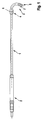
- the electrode catheter serving for cardiac therapy has an elongate, tube-like catheter body 1, which is provided at its proximal end with a connector 2 for connection to a corresponding implant.
- a ring electrode 4 and directly at the tip of the distal end 3 a head electrode 5 is arranged.
- These electrodes 4, 5 serve to deliver or measure an electrical signal, in this case an electrocardial signal via its external electrode contact surface 6, 7, for example, for reliable and effective defibrillation or diagnostics for the early detection of atrial fibrillation and cardiac insufficiency progression.
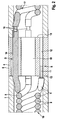
- FIG. 2 a first embodiment for the connection of the electrodes 4, 5 to corresponding supply lines 8, 9 to explain.
- two supply lines 8, 9 in the form of a quadruple coil 10 are brought from the proximal end.
- the two supply lines 8 for the ring electrode 4 are coupled to the ring electrode 4 with the aid of a plug connection S to be explained in more detail.
- the two supply lines 9 for the in FIG. 2 unrecognizable head electrode 5 (FIG. FIG. 1 ) are guided through the ring electrode 4 from proximal to distal with the aid of a feedthrough designated as a whole by D.
- the two leads 8 are led away in the axial direction and their ends 11 stripped.
- the respective stripped end is inserted into an axially parallel receiving bore 12 or receptacle with lying in the catheter body 1, annular end face 13 of the ring electrode 4 and there firmly bonded, for example by laser or resistance welding contact firmly and mechanically firmly.
- longitudinal axially parallel feedthrough holes 14 are provided in the ring electrode 4, which extend between the proximal end face 13 and the distal end face 15 of the ring electrode 4.
- the axially parallel away from the quadruple coil 10 leads 9 lead with this insulated, straight leg through the feedthrough hole 14 therethrough.
- Their stripped ends 16 are connected to a double helix 17, which continues isodiametrically to the head electrode 5, not shown, and is connected there accordingly.
- the electrical contact between the end 16 of the leads 9 and the double helix 17 can be made for example via a material connection.
- the central opening 18 of the ring electrode 4 serves - as well as the inner openings of the helices 10, 17 - for the implementation of the mandrels and guidewires for the electrode catheter.
- the electrode catheter is structurally constructible as a modular system.
- the ring electrode 4 in each case two between the end faces 13, 15 longitudinal axial parallel extending receiving or feedthrough holes 12, 14.
- a metallic crimp shaft 19 is seated, which is electrically contact-connected to the ring electrode 4 and is mechanically fixed in the receiving bore 12, for example by press-fitting or integral connection.
- the insertion depth of the Crimp shaft 19 is limited by a stop shoulder 20. Outside the receiving bore 12, the crimp shaft 19 has a crimp pin 21.
- the stripped ends 11 of the lead 8 for the ring electrode 4 are inserted into a crimp sleeve 22 which sits on the crimp pin 21.
- a conventional crimping of the crimp sleeve 22 a secure mechanical and electrical connection between the ends 11 of the lead 8 and the crimp shaft 19 is provided.
- This crimp connection of the wires to the electrode is also interpretable as a welded connection using similar components.
- top electrode 5 ( FIG. 1 ) is a corresponding crimp shaft 23 is inserted with a surrounding insulating sleeve 24 in the feedthrough holes 14 in the ring electrode 4.
- the assembly of Crimpschaft 23 and insulating sleeve 24 is held stable, for example by pressing in the feedthrough bore 14.
- the insertion depth of the crimp shaft 23 in the insulating sleeve 24 is in turn limited by a stop shoulder 20, outside of which a crimp pin 25 is formed proximally.
- the stripped end 16 of the supply lines 9 is inserted into a crimping sleeve 26 which is seated on the crimping pin 25.
- distal end 27 projects beyond the insulating sleeve 24 and, together with a crimping sleeve 28 inserted thereon, serves to connect the stripped, axially routed wires of the double helix 17 leading distally to the top electrode 5.
- the ring electrode 4 according to FIG. 3 has a central opening 18 for passage of the stylet and guidewires.
- the ring electrode 4 is formed as a massive ring electrode is in the in FIG. 4
- the ring electrode 4 ' is provided with an external, thin-walled electrode ring 30, which forms the electrode contact surface 6.
- a substantially cylindrical core 31 made of insulating plastic, whose axial length in the peripheral region of the electrode ring 30 corresponds.
- An opening 18 is centrally provided on the core 31, which is extended by corresponding collar projections 32 with respect to the axial length of the core 31. This opening 18 again serves to pass the mandrel.
- the crimping sleeve 34 seated therein is arranged in an electrically insulated manner from the electrode ring 30.
- the stripped ends 16 of the leads 9 stuck in the proximal ends of the crimp barrel 34.
- the distal ends of the stripped ends 29 of the double helix 17 are inserted.
- a mechanically and electrically secure connection between the double helix 17 and the leads 9 is created.
- This crimp connection of the wires to the electrode is also interpretable as a welded connection using similar components.
- FIG. 4 of the two plug-in connections S and bushings D only a single can be seen in the sectional view.
- the plug connection S and the bushings D according to the Figures 2 and 3 are mutually exchangeable, that is, a plug connection S according to FIG. 2 with a bushing D according to FIG. 3 and vice versa can be combined.
Landscapes
- Health & Medical Sciences (AREA)
- Heart & Thoracic Surgery (AREA)
- Vascular Medicine (AREA)
- Cardiology (AREA)
- Engineering & Computer Science (AREA)
- Biomedical Technology (AREA)
- Nuclear Medicine, Radiotherapy & Molecular Imaging (AREA)
- Radiology & Medical Imaging (AREA)
- Life Sciences & Earth Sciences (AREA)
- Animal Behavior & Ethology (AREA)
- General Health & Medical Sciences (AREA)
- Public Health (AREA)
- Veterinary Medicine (AREA)
- Electrotherapy Devices (AREA)
- Measurement And Recording Of Electrical Phenomena And Electrical Characteristics Of The Living Body (AREA)
Description
- Die Erfindung betrifft einen Elektrodenkatheter insbesondere zur Kardialtherapie mit den im Oberbegriff des Patentanspruches 1 angegebenen Merkmalen.
- Derartige Elektrodenkatheter sind in unterschiedlichsten Ausführungsformen durch offenkundige Vorbenutzung auch der vorliegenden Anmelderin bekannt und umfassen als Basiskomponenten einen langgestreckten, schlauchartigen Katheterkörper, mindestens eine Elektrode zur Abgabe oder Messung eines elektrischen, insbesondere elektrokardialen Signals über ihre äußere Elektrodenkontaktfläche, mindestens eine erste Zuleitung zum elektrischen Anschluss dieser Elektrode und mindestens eine zweite Zuleitung zum elektrischen Anschluss einer weiteren Elektrode. Typischerweise sind diese Elektroden als zwei am distalen Ende des Elektrodenkatheters mit axialem Abstand sitzende Ringelektroden oder eine Ring- und eine Kopfelektrode ausgelegt, über die Reizleitungssignale des Herzens gemessen oder elektrische Impulse z.B. zum Beenden eines Vorhofflimmerns abgegeben werden.
- Für die Konfiguration der Elektrodenzuleitungen sind grundsätzlich drei unterschiedliche Typen bekannt. Der erste Typ ist die so genannte koradiale Wendel, bei der die zwei Zuleitungen analog einem Gewinde mit zwei oder mehr Gängen parallel zueinander gewickelt und voneinander isoliert sind. Bei solchen koradialen Wendeln werden die Drähte zur Kontaktierung einer Ringelektrode aus dem Wendelverbund tangential ausgelenkt und abisoliert. Die Drähte werden dann zwischen einer Innen- und Außenhülse geklemmt und gecrimpt oder verschweißt.
- Nachteilig beim Anschließen und Durchführen der Zuleitungen bei solchen koradialen Wendeln ist die Tatsache, dass das tangentiale Herausführen der Drähte und das Einklemmen zwischen zwei Hülsen vergleichsweise viel Bauraum erfordert, was das Ziel eines möglichst kleinen, isodiametrischen Elektrodendurchmessers erschwert. Ferner ist die Wickeltechnik sehr aufwendig und damit kostenintensiv.
- Der zweite Typ von Elektrodenzuleitungen ist die koaxiale Wendel welche über einen wendelförmigen Innenleiter, der beispielsweise zu einer Kopfelektrode führt, und einen wendelförmigen Außenleiter, der eine proximal davor angeordnete Ringelektrode kontaktiert verfügt. Die Wendeln werden mit der Kopf- bzw. Ringelektrode mittels Schweißen oder Crimpen verbunden. Nachteilig bei diesem Zuleitungstyp ist die Tatsache, dass aufgrund der beiden koaxial ineinander sitzenden Wendeln das Erreichen eines möglichst kleinen Elektrodendurchmessers im mm-Bereich problematisch ist. Auch für multipolare Elektrodentypen kann diese Zuleitungstechnik praktisch ausgeschlossen werden.
- Schließlich ist als Zuleitungstechnik noch ein so genannter Mehrlumenaufbau bekannt, bei dem ein schlauchartiger Katheterkörper entlang des Elektrodenkatheters über mindestens zwei Lumen verfügt. Durch eines der beiden Lumen verläuft ein dünnes Drahtseil zur Ringelektrode, durch das andere Lumen wird eine Wendel beispielsweise zu einer Kopfelektrode geführt. Das Drahtseil verläuft dabei axial ausgerichtet zur Wendel und wird mit der Ringelektrode verschweißt oder gecrimpt. Die Wendel führt bis zum Elektrodenkopf und wird mit dieser ebenfalls verschweißt oder gecrimpt.
- Nachteilig bei diesem Mehrlumenaufbau ist die Tatsache, dass aufgrund der Einhaltung von Mindestwandstärken für die Außenisolation die Auslegung einer multipolaren Elektrode schwierig ist. Der Elektrodenaufbau ist ferner unsymmetrisch und es existiert, da die Ringelektrode nur über ein Seil mit dem Anschlussstecker verbunden ist, keine Redundanz für die elektrische Kontaktierung der Ringelektrode. Auch kann die Dauerfestigkeit der Kontakte zwischen dem Zuleitungs-Drahtseil und der jeweiligen Elektrode problematisch sein.
- Die
US 6,249,708 B 1 offenbart einen Mehrleiter-Elektrodenkatheter, bei dem eine zentrale Wendel bis zu einer Kopfelektrode geführt und mit dieser verschweißt ist. Um diese Wendel ist ein Isolierkörper versehen, der in seiner Umfangsfläche mit verdrillt laufenden Rillen versehen ist. In diesen sind jeweils Zuleitungen für eine Ringelektrode eingesetzt. Auch diese Konstruktion ist den Koaxial-Wendeln mit den oben beschriebenen Nachteilen zuzuordnen. - Die
US 6,757,970 B1 zeigt einen Mehrfachelektrodenkatheter, bei dem die Elektrodenzuleitungen gemeinsam in einer mehrgängigen Wendel geführt und die Enden aus dem Wendelverbund radial weggeführt sind. Die Kontaktierung der abstehenden Enden erfolgt in aufwendiger Weise über das Umbiegen von Kontaktlaschen an den streifenförmigen Ringelektroden, wobei durch das Umbiegen die abstehenden Enden der Zuleitungen eingeklemmt werden. Anschließend muss die Streifenkonfiguration der Kontakte noch durch ein Werkzeug zum Einrollen in die lang gestreckt zylindrische Form des Katheters gezogen werden. Diese Konstruktion mit ihrer spezifischen Fertigungsweise erscheint im Hinblick auf die filigrane Ausgestaltung von Elektrodenkathetern äußerst diffizil. - Die
US 2006/037195 zeigt einem Elektrodenkatheter gemäß dem Oberbegriff des Anspruchs 1. - Ausgehend von den geschilderten Problemen des Standes der Technik liegt der Erfindung die Aufgabe zugrunde, Elektrodenzuleitungen an eine z.B. Ringelektrode anzubinden und gleichzeitig Zuleitungen für distal dieser Elektrode liegende weitere Elektroden durchzuführen, wobei konstruktionsbedingt geringe isodiametrische Elektrodendurchmesser erreichbar, die Weiterführung von Zuleitungen zu weiter distal gelegenen Elektroden einfacher gestaltet sein sollen und damit insgesamt eine bi- oder multipolare Elektrode mit weniger Aufwand bei der Kontaktierung realisierbar wird.
- Diese Aufgabe wird durch die Merkmale des Anspruchs 1 und die im Kennzeichnungsteil des Anspruches 1 angegebene Grundkonzeption gelöst, die charakterisiert ist durch
- eine Steckanschlussverbindung zwischen der ersten Zuleitung und der entsprechenden Elektrode sowie
- eine isolierte Durchführung der zweiten Zuleitung durch diese Elektrode.
- In vorteilhafter Weise ergibt sich durch diese Konzeption die Möglichkeit, einen Wechsel zwischen verschiedenen Wendeln proximal und distal einer Elektrode zu realisieren, beispielsweise von einer Vierfach-Wendel proximal vor einer Elektrode auf eine Zweifach-Wendel distal von dieser Elektrode. Bi- und multipolare Elektroden genauso wie unipolare Elektroden können dabei mit identischen Elektrodenformen realisiert werden, was eine Art Baukastensystem ergibt. Gleichzeitig kann eine kompakte Bauweise mit entsprechend kleinem Außendurchmesser des Elektrodenkatheters erreicht werden.
- Die abhängigen Ansprüche kennzeichnen vorteilhafte Weiterbildungen der Erfindung, deren Merkmale, Einzelheiten und Vorteile anhand der Beschreibung der Ausführungsbeispiele anhand der beigefügten Zeichnungen näher erläutert werden. Es zeigen:
- Fig. 1
- eine Gesamtansicht eines bipolaren Elektrodenkatheters, und
- Fig. 2 bis 4
- ausschnittsweise, vergrößerte Längsaxialschnitte des Elektrodenkatheters im Bereich einer Ringelektrode in unterschiedlichen Ausführungsformen.
- Wie insbesondere aus
Figur 1 hervorgeht, weist der zur Kardialtherapie dienende Elektrodenkatheter einen langgestreckten, schlauchartigen Katheterkörper 1 auf, der an seinem proximalen Ende mit einem Anschlussstecker 2 zur Verbindung mit einem entsprechenden Implantat versehen ist. Im Bereich des distalen Endes 3 ist eine Ringelektrode 4 sowie unmittelbar an der Spitze des distalen Endes 3 eine Kopfelektrode 5 angeordnet. Diese Elektroden 4, 5 dienen zur Abgabe oder Messung eines elektrischen Signals, im vorliegenden Falle also eines elektrokardialen Signals über ihre äußere Elektrodenkontaktfläche 6, 7 beispielsweise für eine zuverlässige und effektive Defibrillation oder eine Diagnostik zur Früherkennung von Vorhofflimmern und einer Herzinsuffizienzprogression. - Anhand von
Figur 2 ist nun eine erste Ausführungsform für die Anbindung der Elektroden 4, 5 an entsprechende Zuleitungen 8, 9 zu erläutern. So werden in dem schlauchartigen Katheterkörper 1 von proximal her je zwei Zuleitungen 8, 9 in Form einer Vierfach-Wendel 10 herangeführt. Die beiden Zuleitungen 8 für die Ringelektrode 4 sind dabei mit Hilfe einer noch näher zu erläuternden Steckanschlussverbindung S an die Ringelektrode 4 angekoppelt. Die beiden Zuleitungen 9 für die inFigur 2 nicht erkennbare Kopfelektrode 5 (Figur 1 ) sind mit Hilfe einer als Ganzes mit D bezeichneten Durchführung von proximal nach distal durch die Ringelektrode 4 hindurchgeführt. - Aus der Vierfach-Wendel 10 werden die beiden Zuleitungen 8 in axialer Richtung weggeführt und deren Enden 11 abisoliert. Das jeweilige abisolierte Ende wird in eine axialparallele Aufnahmebohrung 12 oder Aufnahme mit in der innerhalb des Katheterkörpers 1 liegenden, ringförmigen Stirnfläche 13 der Ringelektrode 4 eingesteckt und dort stoffschlüssig, beispielsweise durch Lasern oder Widerstandsschweißen kontaktsicher und mechanisch fest verbunden.
- Für die beiden Zuleitungen 9 der Kopfelektrode 5 sind längsaxialparallele Durchführungsbohrungen 14 in der Ringelektrode 4 vorgesehen, die zwischen der proximal liegenden Stirnfläche 13 und der distal liegenden Stirnfläche 15 der Ringelektrode 4 verlaufen. Die axialparallel von der Vierfach-Wendel 10 weggeführten Zuleitungen 9 führen mit diesem isolierten, geraden Schenkel durch die Durchführungsbohrung 14 hindurch. Ihre abisolierten Enden 16 sind an eine Zweifach-Wendel 17 angebunden, die isodiametral bis zur nicht gezeigten Kopfelektrode 5 weiterführt und dort entsprechend angeschlossen ist. Die elektrische Kontaktierung zwischen dem Ende 16 der Zuleitungen 9 und der Zweifach-Wendel 17 kann beispielsweise über eine stoffschlüssige Verbindung hergestellt werden.
- Die zentrale Öffnung 18 der Ringelektrode 4 dient ― genauso wie die Innenöffnungen der Wendeln 10, 17 ― für die Durchführung der Mandrins bzw. von Führungsdrähten für den Elektrodenkatheter.
- Diese Art der Kontaktierung lässt sich auch auf den Elektrodenkopf und auf den Stecker zu einem Herzschrittmachergerät übertragen. Somit ist der Elektrodenkatheter konstruktionstechnisch als Baukastensystem aufbaubar.
- Die in
Figur 3 gezeigte Ausführungsform der Steckanschlussverbindung S und der Durchführung D für die Zuleitungen 8, 9 beruht grundsätzlich auf einer Crimptechnik. So weist die Ringelektrode 4 wiederum jeweils zwei zwischen den Stirnflächen 13, 15 längsaxial parallel verlaufende Aufnahme- bzw. Durchführungsbohrungen 12, 14 auf. In den Aufnahmebohrungen 12 sitzt jeweils ein metallischer Crimpschaft 19, der mit der Ringelektrode 4 elektrisch kontaktverbunden und mechanisch beispielsweise durch Einpressen oder stoffschlüssige Verbindung in der Aufnahmebohrung 12 fixiert ist. Die Einstecktiefe des Crimpschaftes 19 ist dabei durch eine Anschlagschulter 20 begrenzt. Außerhalb der Aufnahmebohrung 12 weist der Crimpschaft 19 einen Crimpstift 21 auf. Die abisolierten Enden 11 der Zuleitung 8 für die Ringelektrode 4 sind in eine Crimphülse 22 eingesteckt, die auf dem Crimpstift 21 sitzt. Durch eine übliche Vercrimpung der Crimphülse 22 wird eine sichere mechanische und elektrische Verbindung zwischen den Enden 11 der Zuleitung 8 und dem Crimpschaft 19 geschaffen. Diese Crimpanbindung der Drähte an die Elektrode ist auch als Schweißanbindung auslegbar unter Verwendung gleichartiger Bauteile. - Zur Durchführung der Zuleitung 9 für die in
Figur 3 nicht dargestellte Kopfelektrode 5 (Figur 1 ) ist ein entsprechender Crimpschaft 23 mit einer ihn umgebenden Isolierhülse 24 in die Durchführungsbohrungen 14 in der Ringelektrode 4 eingesetzt. Die Baugruppe aus Crimpschaft 23 und Isolierhülse 24 ist beispielsweise durch Verpressen stabil in der Durchführungsbohrung 14 gehalten. Die Einstecktiefe des Crimpschaftes 23 in die Isolierhülse 24 ist wiederum über eine Anschlagschulter 20 begrenzt, außerhalb derer proximal ein Crimpstift 25 ausgebildet ist. Analog der Anbindung der Zuleitung 8 ist auch hier das abisolierte Ende 16 der Zuleitungen 9 in eine Crimphülse 26 eingesteckt, die auf dem Crimpstift 25 sitzt. Durch eine Vercrimpung dieser Crimphülse 26 wird eine mechanisch und elektrisch stabile Verbindung zwischen den Zuleitungen 9 und den entsprechenden Crimpschäften 23 geschaffen. - Deren distales Ende 27 ragt über die Isolierhülse 24 hinaus und dient zusammen mit einer darauf gesteckten Crimphülse 28 zur Anbindung der abisolierten, axial weggeführten Drähten der distal zur Kopfelektrode 5 führenden Zweifach-Wendel 17.
- Auch die Ringelektrode 4 gemäß
Figur 3 weist eine zentrale Öffnung 18 zur Durchführung des Mandrins und von Führungsdrähten auf. - Während die Ringelektrode 4 gemäß den
Figuren 2 und3 als massive Ringelektrode ausgebildet ist, ist bei der inFigur 4 gezeigten Ausführungsform die Ringelektrode 4' mit einem außen liegenden, dünnwandigen Elektrodenring 30 versehen, der die Elektrodenkontaktfläche 6 bildet. In der Ringöffnung sitzt ein im Wesentlichen zylindrischer Kern 31 aus isolierendem Kunststoff, dessen Axiallänge im peripheren Bereich der des Elektrodenrings 30 entspricht. Zentral ist am Kern 31 eine Öffnung 18 vorgesehen, die durch entsprechende Kragenvorsprünge 32 gegenüber der Axiallänge des Kerns 31 verlängert ist. Diese Öffnung 18 dient wiederum zur Durchführung des Mandrins. - Für den Anschluss der beiden Zuleitungen 8 der Ringelektrode 4' sind im Bereich der Peripherie des Kerns 31 axialparallel verlaufende, radial nach außen schlitzartig offene Aufnahmebohrungen 12' vorgesehen, in denen metallische Crimphülsen 33 eingesetzt sind. Diese liegen somit an dem Elektrodenring 30 an und stellen somit eine elektrische Verbindung zu diesem her. Die abisolierten Enden 11 der Zuleitungen 8 stecken in diesen Crimphülsen 33 und sind durch eine entsprechende Vercrimpung mechanisch und elektrisch fest damit verbunden.
- Für die Durchführung D der Zuleitungen 9 zur Kopfelektrode 5 hin sind im Kern 31 Durchführungsbohrungen 14' axial parallel eingebracht, die mit Radialabstand von der zentralen Achse und dem Elektrodenring 30 positioniert sind. Damit ist die darin sitzende Crimphülse 34 elektrisch isoliert vom Elektrodenring 30 angeordnet. Die abisolierten Enden 16 der Zuleitungen 9 stecken in den proximalen Enden der Crimphülse 34. In deren distalen Enden sind die abisolierten Enden 29 der Zweifach-Wendel 17 eingesteckt. Durch eine entsprechende Vercrimpung der Crimphülse 34 an ihrem distalen und proximalen Ende ist eine mechanisch und elektrisch sichere Verbindung zwischen der Zweifach-Wendel 17 und den Zuleitungen 9 geschaffen. Diese Crimpanbindung der Drähte an die Elektrode ist auch als Schweißanbindung auslegbar unter Verwendung gleichartiger Bauteile.
- Der guten Ordnung halber wird darauf hingewiesen, dass in
Figur 4 von den jeweils zwei Steckanschlussverbindungen S und Durchführungen D nur eine einzige in der Schnittdarstellung erkennbar sind. Ferner ist festzuhalten, dass die Steckanschlussverbindungen S und die Durchführungen D gemäß denFiguren 2 und3 wechselseitig austauschbar sind, dass also eine Steckanschlussverbindung S gemäßFigur 2 mit einer Durchführung D gemäßFigur 3 und umgekehrt kombiniert werden kann.
Claims (12)
- Elektrodenkatheter, insbesondere zur Kardialtherapie, umfassend- einen langgestreckten, schlauchartigen Katheterkörper (1),- eine Elektrode (4, 5) zur Abgabe oder Messung eines elektrischen, insbesondere elektrokardialen Signals über ihre äußere Elektrodenkontaktfläche (6, 7),- mindestens eine erste Zuleitung (8) zum elektrischen Anschluss der Elektrode (4, 4'), und- mindestens eine zweite Zuleitung (9) zum elektrischen Anschluss einer weiteren Elektrode (5), wobei die erste(n) und zweite(n) Zuleitung(en) (8, 9) gemeinsam als coradiale Mehrfachwendel (10) von proximal zu der Elektrode (4, 4') herangeführt sind,- eine Steckanschlussverbindung (S) zwischen der ersten Zuleitung (8) und der Elektrode (4, 4'), sowie- eine isolierte Durchführung (D) der zweiten Zuleitung (9) durch die Elektrode (4, 4'),dadurch gekennzeichnet, dass- die an die Elektrode (4, 4') anzuschließenden oder durch diese durchzuführenden Enden (11, 16) der Zuleitungen (8, 9) längsaxialparallel aus dem Wendelverbund weggeführt sind,- die isolierte Durchführung (D) der zweiten Zuleitung(en) (9) in längsaxialparallelen Durchgangsbohrungen (14,14') durch die Elektrode (4, 4') hindurchgeführt sind, und- die durch die Elektrode (4, 4') durchgeführte(n) zweite(n) Zuleitung(en) (9) mit einer distal weiterführenden Wendelleitung (17) verbunden sind.
- Elektrodenkatheter nach Anspruch 1, dadurch gekennzeichnet, dass die Steckanschlussverbindung (S) als Aufnahmebohrung (12) oder Aufnahmenut in einer im Katheterkörper (1) liegenden Stirnfläche (13) der Elektrode (4, 4') ausgelegt ist, in die das abisolierte Ende (11) der ersten Zuleitung (8) eingesteckt und fixiert ist.
- Elektrodenkatheter nach Anspruch 1, dadurch gekennzeichnet, dass die Steckanschlussverbindung (S) als Crimpverbindung ausgelegt ist, die einen in der Elektrode (4) sitzenden Crimpschaft (19) mit von einer im Katheterkörper (1) liegenden Stirnfläche (13) der Elektrode (4) abstehendem Crimpstift (21) sowie eine Crimpstift (21) und abisoliertes Ende (11) der ersten Zuleitung (8) verbindende Crimphülse (22) aufweist.
- Elektrodenkatheter nach einem der vorgenannten Ansprüche, dadurch gekennzeichnet, dass die Elektrode (4) als massive Ringelektrode ausgebildet ist.
- Elektrodenkatheter nach Anspruch 1, dadurch gekennzeichnet, dass die Elektrode (4') einen außen liegenden, dünnwandigen Elektrodenring (30) und einen isolierenden Kern (31) aufweist, wobei in einer zum Elektrodenring (30) hin offenen Aufnahmebohrung (12') des Kerns (31) eine Crimphülse oder Schweißhülse (33) mit elektrischem Kontakt zum Elektrodenring (30) angeordnet und mit dem abisolierten Ende (11) der ersten Zuleitung (8) vercrimpt oder verschweißt ist.
- Elektrodenkatheter nach einem der Ansprüche 1 bis 4, dadurch gekennzeichnet, dass die isolierte Durchführung (D) für die zweite Zuleitung (9) als Durchgangsbohrung (14) durch die Elektrode (4) ausgebildet ist, durch die die isolierte zweite Zuleitung (9) hindurchgeführt ist.
- Elektrodenkatheter nach Anspruch 6, dadurch gekennzeichnet, dass durchgeführte zweite Zuleitung (9) distal der isolierten Durchführung (D) an eine weiterführende Leitungswendel (17) angeschlossen ist.
- Elektrodenkatheter nach einem der Ansprüche 1 bis 4, dadurch gekennzeichnet, dass die isolierte Durchführung (D) für die zweite Zuleitung (9) durch einen isoliert durch die Elektrode (4) geführten Crimpschaft (23) gebildet ist, der aufweist- proximal einen von einer im Katheterkörper (1) liegenden Stirnfläche (13) der Elektrode (4) abstehenden Crimpstift (25) sowie eine jeweils Crimpstift (25) und abisoliertes Ende (16) der zweiten Zuleitung (9) verbindende Crimphülse (26), und- distal einen von einer im Katheterkörper (1) liegenden weiteren Stirnfläche (15) der Elektrode (4) abstehenden Crimpstift (27) sowie eine jeweils diesen Crimpstift (27) und ein abisoliertes Ende (29) einer distal weiterführenden Leitung (17) verbindende Crimphülse (28).
- Elektrodenkatheter nach Anspruch 3 oder 8, dadurch gekennzeichnet, dass der Crimpschaft (19, 23) eine Anschlagschulter (20) zur Begrenzung seiner Einstecktiefe in die Elektrode (4) aufweist.
- Elektrodenkatheter nach Anspruch 5, dadurch gekennzeichnet, dass die zweite Zuleitung (9) durch den isolierenden Kern (31) mit Radialabstand zum Elektrodenring (30) durchgeführt ist.
- Elektrodenkatheter nach Anspruch 10, dadurch gekennzeichnet, dass eine Crimphülse (34) im isolierenden Kern (31) mit Radialabstand zum Elektrodenring (30) durchgeführt ist, die proximal mit dem abisolierten Ende (16) der zweiten Zuleitung (9) und distal mit dem abisolierten Ende (29) einer distal weiterführenden Leitung (17) vercrimpt ist.
- Elektrodenkatheter nach einem der vorgenannten Ansprüche, dadurch gekennzeichnet, dass die erste und zweite Zuleitung (8, 9) mindestens doppelt vorhanden sind.
Applications Claiming Priority (1)
| Application Number | Priority Date | Filing Date | Title |
|---|---|---|---|
| US37840610P | 2010-08-31 | 2010-08-31 |
Publications (2)
| Publication Number | Publication Date |
|---|---|
| EP2422839A1 EP2422839A1 (de) | 2012-02-29 |
| EP2422839B1 true EP2422839B1 (de) | 2013-04-03 |
Family
ID=44653898
Family Applications (1)
| Application Number | Title | Priority Date | Filing Date |
|---|---|---|---|
| EP11176444A Not-in-force EP2422839B1 (de) | 2010-08-31 | 2011-08-03 | Elektrodenkatheter, insbesondere zur Kardialtherapie |
Country Status (2)
| Country | Link |
|---|---|
| US (1) | US8504173B2 (de) |
| EP (1) | EP2422839B1 (de) |
Families Citing this family (2)
| Publication number | Priority date | Publication date | Assignee | Title |
|---|---|---|---|---|
| EP2604312B1 (de) | 2011-12-13 | 2015-07-01 | BIOTRONIK SE & Co. KG | Leitungswendelanordnung und Elektrodenkatheteranordnung, insbesondere zur Kardialtherapie |
| DE102015121815A1 (de) * | 2015-12-15 | 2017-06-22 | Biotronik Se & Co. Kg | Implantierbare Elektrodenleitung und Satz von Elektrodenleitungs-Modulen |
Family Cites Families (10)
| Publication number | Priority date | Publication date | Assignee | Title |
|---|---|---|---|---|
| US4592372A (en) * | 1984-05-22 | 1986-06-03 | Cordis Corporation | Pacing/sensing electrode sleeve and method of forming same |
| US5330522A (en) * | 1992-12-29 | 1994-07-19 | Siemens Pacesetter, Inc. | Ring electrode for a multilumen lead and method of constructing a multilumen lead |
| US5417208A (en) * | 1993-10-12 | 1995-05-23 | Arrow International Investment Corp. | Electrode-carrying catheter and method of making same |
| US6249708B1 (en) | 1997-08-26 | 2001-06-19 | Angeion Corporation | Fluted channel construction for a multi-conductor catheter lead |
| IL126905A0 (en) * | 1998-11-05 | 1999-09-22 | Impulse Dynamics Ltd | Multi-electrode catheter |
| US20050004642A1 (en) * | 1998-11-09 | 2005-01-06 | Medtronic, Inc. | Implantable medical lead including overlay |
| US6757970B1 (en) | 2000-11-07 | 2004-07-06 | Advanced Bionics Corporation | Method of making multi-contact electrode array |
| US20030009094A1 (en) * | 2000-11-15 | 2003-01-09 | Segner Garland L. | Electrophysiology catheter |
| US7292894B2 (en) * | 2002-09-27 | 2007-11-06 | Medtronic, Inc. | Methods and apparatus for joining small diameter conductors within medical electrical leads |
| US7067765B2 (en) * | 2004-08-23 | 2006-06-27 | Medtronic, Inc. | Methods for forming electrically active surfaces for medical electrical leads |
-
2011
- 2011-08-03 EP EP11176444A patent/EP2422839B1/de not_active Not-in-force
- 2011-08-08 US US13/205,232 patent/US8504173B2/en not_active Expired - Fee Related
Also Published As
| Publication number | Publication date |
|---|---|
| EP2422839A1 (de) | 2012-02-29 |
| US20120053668A1 (en) | 2012-03-01 |
| US8504173B2 (en) | 2013-08-06 |
Similar Documents
| Publication | Publication Date | Title |
|---|---|---|
| EP1127552B1 (de) | Ablationskatheter zur Erzeugung linearer Läsionen in Herzmuskelgewebe | |
| DE69820418T2 (de) | Spulendrahtisolierung für biomedizinische leiter | |
| EP0491979A1 (de) | Herzschrittmacher-Katheter mit zwei Polen | |
| DE19957241B4 (de) | Elektrische Leitung für medizinische Zwecke und System zur Einführung derselben | |
| DE60111222T2 (de) | Elektrisch isolierte leitung mit mehreren leitern | |
| EP3189561B1 (de) | Crimpkontakt | |
| DE3140075C2 (de) | ||
| DE102008008927A1 (de) | Elektrodenleitung und Anschlussstück für elektromedizinische Implantate | |
| EP2604312B1 (de) | Leitungswendelanordnung und Elektrodenkatheteranordnung, insbesondere zur Kardialtherapie | |
| DE102006037122B3 (de) | Medizinische Elektrode mit wenigstens zwei Polen und einem Stecker und deren Verwendung | |
| EP2422839B1 (de) | Elektrodenkatheter, insbesondere zur Kardialtherapie | |
| EP1955729B1 (de) | Elektrodenleitung und Anschlussstück für einen implantierbaren Herzstimulator | |
| CH653559A5 (en) | Pacemaker electrode | |
| DE3043189A1 (de) | Herzschrittmacher-elektrode | |
| EP2359894A1 (de) | Elektrode mit HF-Filter für aktive medizinische Implantate | |
| DE3427361C1 (de) | Verbindung zwischen einem koaxialen Steckverbinder und einem Koaxialkabel | |
| EP3630266B1 (de) | Elektromedizinischer adapter, elektromedizinische elektrode und elektromedizinischer impulsgeber | |
| EP1754508B1 (de) | Medizinische Elektrodenvorrichtung, insbesondere implantierbare kardiologische Elektrodenvorrichtung | |
| DE102005039038A1 (de) | Medizinische Elektrodenvorrichtung, insbesondere implantierbare kardiologische Elektrodenvorrichtung | |
| EP2918308A1 (de) | Isolationsschlauch für eine elektrische leitung zur medizinischen anwendung und verfahren zur herstellung eines solchen | |
| DE102007039554B4 (de) | Herzschrittmacher-Elektrode mit Schraubwendel und Zuleitungswendel | |
| WO2019174900A1 (de) | Implantat in art einer wickelmanschetten-elektrodenanordnung | |
| DE202005020835U1 (de) | Medizinische Elektrodenvorrichtung, insbesondere implantierbare kardiologische Elektrodenvorrichtung | |
| DE102016121036A1 (de) | Medizintechnischer Applikator und Verfahren | |
| DE4430595C2 (de) | Elektrodenstecker |
Legal Events
| Date | Code | Title | Description |
|---|---|---|---|
| AK | Designated contracting states |
Kind code of ref document: A1 Designated state(s): AL AT BE BG CH CY CZ DE DK EE ES FI FR GB GR HR HU IE IS IT LI LT LU LV MC MK MT NL NO PL PT RO RS SE SI SK SM TR |
|
| AX | Request for extension of the european patent |
Extension state: BA ME |
|
| PUAI | Public reference made under article 153(3) epc to a published international application that has entered the european phase |
Free format text: ORIGINAL CODE: 0009012 |
|
| 17P | Request for examination filed |
Effective date: 20120822 |
|
| RIC1 | Information provided on ipc code assigned before grant |
Ipc: A61N 1/05 20060101AFI20120911BHEP Ipc: A61N 1/02 20060101ALN20120911BHEP Ipc: H01R 4/20 20060101ALI20120911BHEP |
|
| GRAP | Despatch of communication of intention to grant a patent |
Free format text: ORIGINAL CODE: EPIDOSNIGR1 |
|
| GRAS | Grant fee paid |
Free format text: ORIGINAL CODE: EPIDOSNIGR3 |
|
| GRAA | (expected) grant |
Free format text: ORIGINAL CODE: 0009210 |
|
| AK | Designated contracting states |
Kind code of ref document: B1 Designated state(s): AL AT BE BG CH CY CZ DE DK EE ES FI FR GB GR HR HU IE IS IT LI LT LU LV MC MK MT NL NO PL PT RO RS SE SI SK SM TR |
|
| REG | Reference to a national code |
Ref country code: GB Ref legal event code: FG4D Free format text: NOT ENGLISH |
|
| REG | Reference to a national code |
Ref country code: AT Ref legal event code: REF Ref document number: 604303 Country of ref document: AT Kind code of ref document: T Effective date: 20130415 Ref country code: CH Ref legal event code: EP |
|
| REG | Reference to a national code |
Ref country code: IE Ref legal event code: FG4D Free format text: LANGUAGE OF EP DOCUMENT: GERMAN |
|
| REG | Reference to a national code |
Ref country code: DE Ref legal event code: R096 Ref document number: 502011000582 Country of ref document: DE Effective date: 20130529 |
|
| PG25 | Lapsed in a contracting state [announced via postgrant information from national office to epo] |
Ref country code: SI Free format text: LAPSE BECAUSE OF FAILURE TO SUBMIT A TRANSLATION OF THE DESCRIPTION OR TO PAY THE FEE WITHIN THE PRESCRIBED TIME-LIMIT Effective date: 20130403 |
|
| REG | Reference to a national code |
Ref country code: NL Ref legal event code: VDEP Effective date: 20130403 |
|
| REG | Reference to a national code |
Ref country code: LT Ref legal event code: MG4D |
|
| PG25 | Lapsed in a contracting state [announced via postgrant information from national office to epo] |
Ref country code: NL Free format text: LAPSE BECAUSE OF FAILURE TO SUBMIT A TRANSLATION OF THE DESCRIPTION OR TO PAY THE FEE WITHIN THE PRESCRIBED TIME-LIMIT Effective date: 20130403 Ref country code: IS Free format text: LAPSE BECAUSE OF FAILURE TO SUBMIT A TRANSLATION OF THE DESCRIPTION OR TO PAY THE FEE WITHIN THE PRESCRIBED TIME-LIMIT Effective date: 20130803 Ref country code: ES Free format text: LAPSE BECAUSE OF FAILURE TO SUBMIT A TRANSLATION OF THE DESCRIPTION OR TO PAY THE FEE WITHIN THE PRESCRIBED TIME-LIMIT Effective date: 20130714 Ref country code: NO Free format text: LAPSE BECAUSE OF FAILURE TO SUBMIT A TRANSLATION OF THE DESCRIPTION OR TO PAY THE FEE WITHIN THE PRESCRIBED TIME-LIMIT Effective date: 20130703 Ref country code: SE Free format text: LAPSE BECAUSE OF FAILURE TO SUBMIT A TRANSLATION OF THE DESCRIPTION OR TO PAY THE FEE WITHIN THE PRESCRIBED TIME-LIMIT Effective date: 20130403 Ref country code: GR Free format text: LAPSE BECAUSE OF FAILURE TO SUBMIT A TRANSLATION OF THE DESCRIPTION OR TO PAY THE FEE WITHIN THE PRESCRIBED TIME-LIMIT Effective date: 20130704 Ref country code: LT Free format text: LAPSE BECAUSE OF FAILURE TO SUBMIT A TRANSLATION OF THE DESCRIPTION OR TO PAY THE FEE WITHIN THE PRESCRIBED TIME-LIMIT Effective date: 20130403 Ref country code: PT Free format text: LAPSE BECAUSE OF FAILURE TO SUBMIT A TRANSLATION OF THE DESCRIPTION OR TO PAY THE FEE WITHIN THE PRESCRIBED TIME-LIMIT Effective date: 20130805 Ref country code: FI Free format text: LAPSE BECAUSE OF FAILURE TO SUBMIT A TRANSLATION OF THE DESCRIPTION OR TO PAY THE FEE WITHIN THE PRESCRIBED TIME-LIMIT Effective date: 20130403 |
|
| PG25 | Lapsed in a contracting state [announced via postgrant information from national office to epo] |
Ref country code: HR Free format text: LAPSE BECAUSE OF FAILURE TO SUBMIT A TRANSLATION OF THE DESCRIPTION OR TO PAY THE FEE WITHIN THE PRESCRIBED TIME-LIMIT Effective date: 20130403 Ref country code: RS Free format text: LAPSE BECAUSE OF FAILURE TO SUBMIT A TRANSLATION OF THE DESCRIPTION OR TO PAY THE FEE WITHIN THE PRESCRIBED TIME-LIMIT Effective date: 20130403 Ref country code: BG Free format text: LAPSE BECAUSE OF FAILURE TO SUBMIT A TRANSLATION OF THE DESCRIPTION OR TO PAY THE FEE WITHIN THE PRESCRIBED TIME-LIMIT Effective date: 20130703 Ref country code: CY Free format text: LAPSE BECAUSE OF FAILURE TO SUBMIT A TRANSLATION OF THE DESCRIPTION OR TO PAY THE FEE WITHIN THE PRESCRIBED TIME-LIMIT Effective date: 20130403 Ref country code: PL Free format text: LAPSE BECAUSE OF FAILURE TO SUBMIT A TRANSLATION OF THE DESCRIPTION OR TO PAY THE FEE WITHIN THE PRESCRIBED TIME-LIMIT Effective date: 20130403 Ref country code: LV Free format text: LAPSE BECAUSE OF FAILURE TO SUBMIT A TRANSLATION OF THE DESCRIPTION OR TO PAY THE FEE WITHIN THE PRESCRIBED TIME-LIMIT Effective date: 20130403 |
|
| PG25 | Lapsed in a contracting state [announced via postgrant information from national office to epo] |
Ref country code: SK Free format text: LAPSE BECAUSE OF FAILURE TO SUBMIT A TRANSLATION OF THE DESCRIPTION OR TO PAY THE FEE WITHIN THE PRESCRIBED TIME-LIMIT Effective date: 20130403 Ref country code: EE Free format text: LAPSE BECAUSE OF FAILURE TO SUBMIT A TRANSLATION OF THE DESCRIPTION OR TO PAY THE FEE WITHIN THE PRESCRIBED TIME-LIMIT Effective date: 20130403 Ref country code: CZ Free format text: LAPSE BECAUSE OF FAILURE TO SUBMIT A TRANSLATION OF THE DESCRIPTION OR TO PAY THE FEE WITHIN THE PRESCRIBED TIME-LIMIT Effective date: 20130403 Ref country code: DK Free format text: LAPSE BECAUSE OF FAILURE TO SUBMIT A TRANSLATION OF THE DESCRIPTION OR TO PAY THE FEE WITHIN THE PRESCRIBED TIME-LIMIT Effective date: 20130403 |
|
| PLBE | No opposition filed within time limit |
Free format text: ORIGINAL CODE: 0009261 |
|
| STAA | Information on the status of an ep patent application or granted ep patent |
Free format text: STATUS: NO OPPOSITION FILED WITHIN TIME LIMIT |
|
| BERE | Be: lapsed |
Owner name: BIOTRONIK SE & CO. K.G. Effective date: 20130831 |
|
| PG25 | Lapsed in a contracting state [announced via postgrant information from national office to epo] |
Ref country code: RO Free format text: LAPSE BECAUSE OF FAILURE TO SUBMIT A TRANSLATION OF THE DESCRIPTION OR TO PAY THE FEE WITHIN THE PRESCRIBED TIME-LIMIT Effective date: 20130403 Ref country code: IT Free format text: LAPSE BECAUSE OF FAILURE TO SUBMIT A TRANSLATION OF THE DESCRIPTION OR TO PAY THE FEE WITHIN THE PRESCRIBED TIME-LIMIT Effective date: 20130403 |
|
| 26N | No opposition filed |
Effective date: 20140106 |
|
| REG | Reference to a national code |
Ref country code: DE Ref legal event code: R097 Ref document number: 502011000582 Country of ref document: DE Effective date: 20140106 |
|
| PG25 | Lapsed in a contracting state [announced via postgrant information from national office to epo] |
Ref country code: MC Free format text: LAPSE BECAUSE OF FAILURE TO SUBMIT A TRANSLATION OF THE DESCRIPTION OR TO PAY THE FEE WITHIN THE PRESCRIBED TIME-LIMIT Effective date: 20130403 |
|
| REG | Reference to a national code |
Ref country code: FR Ref legal event code: ST Effective date: 20140430 |
|
| PG25 | Lapsed in a contracting state [announced via postgrant information from national office to epo] |
Ref country code: BE Free format text: LAPSE BECAUSE OF NON-PAYMENT OF DUE FEES Effective date: 20130831 |
|
| PG25 | Lapsed in a contracting state [announced via postgrant information from national office to epo] |
Ref country code: FR Free format text: LAPSE BECAUSE OF NON-PAYMENT OF DUE FEES Effective date: 20130902 |
|
| PG25 | Lapsed in a contracting state [announced via postgrant information from national office to epo] |
Ref country code: SM Free format text: LAPSE BECAUSE OF FAILURE TO SUBMIT A TRANSLATION OF THE DESCRIPTION OR TO PAY THE FEE WITHIN THE PRESCRIBED TIME-LIMIT Effective date: 20130403 |
|
| PG25 | Lapsed in a contracting state [announced via postgrant information from national office to epo] |
Ref country code: TR Free format text: LAPSE BECAUSE OF FAILURE TO SUBMIT A TRANSLATION OF THE DESCRIPTION OR TO PAY THE FEE WITHIN THE PRESCRIBED TIME-LIMIT Effective date: 20130403 Ref country code: MT Free format text: LAPSE BECAUSE OF FAILURE TO SUBMIT A TRANSLATION OF THE DESCRIPTION OR TO PAY THE FEE WITHIN THE PRESCRIBED TIME-LIMIT Effective date: 20130403 |
|
| REG | Reference to a national code |
Ref country code: DE Ref legal event code: R082 Ref document number: 502011000582 Country of ref document: DE Representative=s name: RANDOLL, SOEREN, DIPL.-CHEM. UNIV. DR. RER. NA, DE |
|
| PG25 | Lapsed in a contracting state [announced via postgrant information from national office to epo] |
Ref country code: MK Free format text: LAPSE BECAUSE OF FAILURE TO SUBMIT A TRANSLATION OF THE DESCRIPTION OR TO PAY THE FEE WITHIN THE PRESCRIBED TIME-LIMIT Effective date: 20130403 Ref country code: HU Free format text: LAPSE BECAUSE OF FAILURE TO SUBMIT A TRANSLATION OF THE DESCRIPTION OR TO PAY THE FEE WITHIN THE PRESCRIBED TIME-LIMIT; INVALID AB INITIO Effective date: 20110803 Ref country code: LU Free format text: LAPSE BECAUSE OF NON-PAYMENT OF DUE FEES Effective date: 20130803 |
|
| GBPC | Gb: european patent ceased through non-payment of renewal fee |
Effective date: 20150803 |
|
| PG25 | Lapsed in a contracting state [announced via postgrant information from national office to epo] |
Ref country code: GB Free format text: LAPSE BECAUSE OF NON-PAYMENT OF DUE FEES Effective date: 20150803 |
|
| REG | Reference to a national code |
Ref country code: AT Ref legal event code: MM01 Ref document number: 604303 Country of ref document: AT Kind code of ref document: T Effective date: 20160803 |
|
| PG25 | Lapsed in a contracting state [announced via postgrant information from national office to epo] |
Ref country code: AT Free format text: LAPSE BECAUSE OF NON-PAYMENT OF DUE FEES Effective date: 20160803 |
|
| PGFP | Annual fee paid to national office [announced via postgrant information from national office to epo] |
Ref country code: CH Payment date: 20170830 Year of fee payment: 7 Ref country code: DE Payment date: 20170818 Year of fee payment: 7 |
|
| PGFP | Annual fee paid to national office [announced via postgrant information from national office to epo] |
Ref country code: IE Payment date: 20170822 Year of fee payment: 7 |
|
| PG25 | Lapsed in a contracting state [announced via postgrant information from national office to epo] |
Ref country code: AL Free format text: LAPSE BECAUSE OF FAILURE TO SUBMIT A TRANSLATION OF THE DESCRIPTION OR TO PAY THE FEE WITHIN THE PRESCRIBED TIME-LIMIT Effective date: 20130403 |
|
| REG | Reference to a national code |
Ref country code: DE Ref legal event code: R119 Ref document number: 502011000582 Country of ref document: DE |
|
| REG | Reference to a national code |
Ref country code: CH Ref legal event code: PL |
|
| PG25 | Lapsed in a contracting state [announced via postgrant information from national office to epo] |
Ref country code: CH Free format text: LAPSE BECAUSE OF NON-PAYMENT OF DUE FEES Effective date: 20180831 Ref country code: LI Free format text: LAPSE BECAUSE OF NON-PAYMENT OF DUE FEES Effective date: 20180831 |
|
| REG | Reference to a national code |
Ref country code: IE Ref legal event code: MM4A |
|
| PG25 | Lapsed in a contracting state [announced via postgrant information from national office to epo] |
Ref country code: IE Free format text: LAPSE BECAUSE OF NON-PAYMENT OF DUE FEES Effective date: 20180803 Ref country code: DE Free format text: LAPSE BECAUSE OF NON-PAYMENT OF DUE FEES Effective date: 20190301 |