EP2422063B1 - Support monobloc d'equipements en aeronautique - Google Patents
Support monobloc d'equipements en aeronautique Download PDFInfo
- Publication number
- EP2422063B1 EP2422063B1 EP10715537.6A EP10715537A EP2422063B1 EP 2422063 B1 EP2422063 B1 EP 2422063B1 EP 10715537 A EP10715537 A EP 10715537A EP 2422063 B1 EP2422063 B1 EP 2422063B1
- Authority
- EP
- European Patent Office
- Prior art keywords
- console
- flange
- ribs
- support
- extension
- Prior art date
- Legal status (The legal status is an assumption and is not a legal conclusion. Google has not performed a legal analysis and makes no representation as to the accuracy of the status listed.)
- Active
Links
Images

Classifications
-
- F—MECHANICAL ENGINEERING; LIGHTING; HEATING; WEAPONS; BLASTING
- F16—ENGINEERING ELEMENTS AND UNITS; GENERAL MEASURES FOR PRODUCING AND MAINTAINING EFFECTIVE FUNCTIONING OF MACHINES OR INSTALLATIONS; THERMAL INSULATION IN GENERAL
- F16L—PIPES; JOINTS OR FITTINGS FOR PIPES; SUPPORTS FOR PIPES, CABLES OR PROTECTIVE TUBING; MEANS FOR THERMAL INSULATION IN GENERAL
- F16L3/00—Supports for pipes, cables or protective tubing, e.g. hangers, holders, clamps, cleats, clips, brackets
Definitions
- the subject of the present invention is an aeronautical equipment support which is in one piece.
- Aeronautical devices such as turbomachines often include a quantity of ancillary equipment surrounding them, including electrical cables for supply or transmission of signals and controls, as well as fluid transport lines, which must be maintained close to the apparatus.
- Angled supports are typically used, one side of which is fixed to the structure of the apparatus by bolts and the other end of which carries cables, pipes and the like by means of clamps, pairs of resilient blades or other means.
- These supports being generally made by folding sheet metal plates, their rigidity is low and they must be reinforced by ribs joined to both sides of the sheet by edges. The rib is traditionally welded to the plate by a continuous bead or by points, which has the disadvantage of greatly increasing the manufacturing time and bidding these supports.
- An aeronautical equipment support comprising a connection flange to a supporting structure, an equipment attachment bracket and an intermediate reinforcing member, the flange, the reinforcing piece and the bracket being formed of a single plate of folded sheet (hence the monobloc character of the support), the reinforcing piece being composed of two ribs each extending between the flange and the bracket, joined by bent connectors, essentially in oblique directions not perpendicular to a main plane of extension of the flange and to a main plane extension of the console, the console and the flange being free of junction other than the ribs and ribs are connected on either side of the console, is also described in the document FR-2 914 275-A .
- the welded ribs are thus replaced by ribs fully incorporated in the rest of the support. As there are two of them on both sides of the console, they allow a good distribution of forces and therefore a sufficient strength of the support. As the manufacturing operations are limited to cutting a sheet and folding the blank of the support thus cut, the manufacture of the support is easy and fast. It must be admitted, however, that the ribs of this document, to be bent to have a bent section while they are connected continuously to a console and a flange which must remain flat, are responsible for a major manufacturing complication.
- a fundamental object of the invention is to provide an aeronautical equipment support of simpler structure, in practice a single folded sheet metal plate, without any welding, without the resistance to efforts is compromised.
- the invention thus relates to an aeronautical equipment support, comprising a connection flange to a support structure, an equipment attachment console and an intermediate reinforcement piece, the flange, the reinforcement piece and the bracket being formed of a single folded sheet metal plate, the reinforcing member being composed of two ribs each extending between the flange and the bracket joined therein by bent connectors, essentially in oblique directions not perpendicular to a main plane of extension of the flange and a main plane of extension of the console, the console and the flange being free of junction other than the ribs and the ribs connecting on either side of the console, the ribs being planar and said main extension planes of the flange and the bracket being perpendicular to each other the ribs extending in concurrent directions at an angle not flat, the console comprises a plurality of attachment means of the equipment, characterized in that the console extends with a main extension in a direction perpendicular to the plane of the flange and on either side of
- the welded ribs are thus replaced by ribs fully incorporated in the rest of the support. Since they are two in number and other of the console, they allow a good distribution of the efforts and thus a sufficient solidity of the support. As the manufacturing operations are limited to cutting a sheet and folding the blank of the support thus cut, the manufacture of the support is easy and fast.
- the strength of the support is improved since the ribs are flat and said main planes of extension of the flange and the console are perpendicular to each other.
- the support of the figure 1 comprises a main plate 1 composed of a first side 2 and a second side 3 joined at an angle 4 in an angle arrangement or other angle value.
- the sides 2 and 3 are still joined by a reinforcing rib 5 which is supported on them by two edges, respectively 6 and 7.
- the connection is made by welds.
- One of the sides 2 is a flange which comprises bolts 8 for attachment to a structure 9 of an aeronautical apparatus
- the second side 3 is a console which carries, in this particular embodiment, a clamping collar 10 and a clamping clip 11 with two blades opposing elastics for retaining cables or conduits 12.
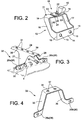
- the support of the figure 2 consists of a single sheet metal plate 13 folded after being cut. It forms a flange portion 14 for attachment to the structure 9 not shown here, which includes bolt holes for attachment. Then there is a pair of ribs 16 and 17, a console 18 carrying the equipment for attaching cables and pipes, such as the collar 10.
- the ribs 16 and 17 are each connected to the flange 14 and the console 18 by fittings 19 which correspond to the folds of the sheet. These connections here are substantially bends at right angles, and the ribs 16 and 17 are curved in a quarter of a circle roughly.
- the console 18 is composed of the ends of the sheet metal plate, which form convergent portions 21 and 22 overlapping at a junction 23.
- the junction can be done without or with a recess 24 of one of the ends 21.
- the ends 21 and 22 are provided with a bolt hole at the junction 23, to screw them to each other and to the collar 10.
- the planes of the ribs 16 and 17 may be parallel or not, and according to the case the support 13 has a general projected shape in rectangle or in trapezium, with the console 18 and the flange 14 of equal widths or not; it is not critical for the properties of the support 13.
- This closed rope rack and box-shaped is particularly rigid even with a fairly thin sheet, thanks among other things to a good recovery efforts produced on the collar 10 by the ribs 15 and 17, which are located symmetrically from and other of it, or a low cantilever relative to the flange 14 due to the small inclination of their main portions 20; and the fittings 19 are continuous and rounded. All of this produces little stress concentration, and no weak area exists.
- the support 32 of the figure 3 comprises as before a flange 26, a pair of ribs 27 and 28 and a console 29. These elements are joined together by connectors 30 bent in the same way as the figure 2 , so that the ribs 27 and 28 are connected by their ends to the flange 26 and the console 29 and that the latter are separated from each other and no other connection between them.
- the flange 26 is first formed as two lugs 26a and 26b separated from each other and extending in divergent directions from their connections 30 to the respective ribs 27 and 28.
- the planes of the ribs 27 and 28 are no longer perpendicular to that of the console 29, but oblique to it so that they converge towards one another at an acute angle from the tabs 26a and 26b, the support 32 having a generally trapezoidal shape.
- the obliqueness of the ribs 27 and 28 with respect to the flange 26 no longer exists; they rise next to the plane of the bridle 26, without moving away from it.
- the console 29 is here continuous and unitary.
- FIG. 4 Another (unclaimed) embodiment of support embodiment 33 will now be described by means of the figure 4 . It looks like that of the figure 3 except that the console, now 34, extends mainly in the same direction as the flange 26, and that the ribs, now 35 and 36, do not widen towards it.
- This support 33 of simple and compact construction is suitable for supporting a smaller number of elements under penalty of excessive elongation. It may further comprise a plurality of bolt holes 37 substantially aligned in the direction of extension of the flange 26.
Landscapes
- Engineering & Computer Science (AREA)
- General Engineering & Computer Science (AREA)
- Mechanical Engineering (AREA)
- Connection Of Plates (AREA)
- Clamps And Clips (AREA)
- Supports For Pipes And Cables (AREA)
- Details Of Indoor Wiring (AREA)
Description
- L'invention présente a pour sujet un support d'équipements en aéronautique qui soit monobloc.
- Les appareils aéronautiques comme les turbomachines comprennent souvent une quantité d'équipements auxiliaires les entourant, notamment des câbles électriques d'alimentation ou de transmission de signaux et de commandes, ainsi que des canalisations de transport de fluides, qui doivent être maintenues près de l'appareil. On utilise typiquement des supports coudés, dont un côté est fixé à la structure de l'appareil par des boulons et dont l'autre extrémité porte les câbles, canalisations et autres par des colliers de serrage, des paires de lames élastiques ou d'autres moyens. Ces supports étant généralement réalisés en pliant des plaques de tôles, leur rigidité est faible et ils doivent être renforcés par des nervures jointes aux deux côtés de la tôle par des arêtes. La nervure est traditionnellement soudée à la plaque par un cordon continu ou par points, ce qui a l'inconvénient d'augmenter beaucoup le temps de fabrication et d'enchérir ces supports.
- Un support d'équipements en aéronautique, comprenant une bride de raccordement à une structure porteuse, une console d'attache des équipements et une pièce de renfort intermédiaire, la bride, la pièce de renfort et la console étant formées d'une seule plaque de tôle pliée (d'où le caractère monobloc du support), la pièce de renfort étant composée de deux nervures s'étendant chacune entre la bride et la console en y étant jointes par des raccords coudés, essentiellement dans des directions obliques non perpendiculaires à un plan principal d'extension de la bride et à un plan principal d'extension de la console, la console et la bride étant dépourvues de jonction autre que les nervures et les nervures se raccordent de part et d'autre de la console, est aussi décrit dans le document
FR-2 914 275-A - Les nervures soudées sont ainsi remplacées par des nervures pleinement incorporées au reste du support. Comme elles sont au nombre de deux de part et d'autre de la console, elles permettent une bonne répartition des efforts et donc une solidité suffisante du support. Comme les opérations de fabrication se limitent à un découpage d'une tôle et au pliage de l'ébauche du support ainsi découpée, la fabrication du support est facile et rapide. On doit toutefois admettre que les nervures de ce document, devant être pliées pour avoir une section coudée alors qu'elles sont reliées de façon continue à une console et une bride qui doivent rester planes, sont responsables d'une complication importante de fabrication.
- Un but fondamental de l'invention est encore de proposer un support d'équipements en aéronautique de structure plus simple, en pratique d'une seule plaque de tôle pliée, sans aucune soudure, sans que la résistance aux efforts soit compromise.
- Le préambule de la revendication indépendante est fondé sur le contenu de
US 2006/254192 Al, qui n'est toutefois pas relatif à l'aéronautique. - Sous une forme générale, l'invention concerne ainsi un support d'équipements en aéronautique, comprenant une bride de raccordement à une structure porteuse, une console d'attache des équipements et une pièce de renfort intermédiaire, la bride, la pièce de renfort et la console étant formées d'une seule plaque de tôle pliée, la pièce de renfort étant composée de deux nervures s'étendant chacune entre la bride et la console en y étant jointes par des raccords coudés, essentiellement dans des directions obliques non perpendiculaires à un plan principal d'extension de la bride et à un plan principal d'extension de la console, la console et la bride étant dépourvues de jonction autre que les nervures et les nervures se raccordant de part et d'autre de la console, les nervures étant planes et lesdits plans principaux d'extension de la bride et de la console étant perpendiculaires entre eux les nervures s'étendant dans des directions concourantes en faisant un angle non plat, la console comprend une pluralité de moyens d'attache de l'équipement, caractérisé en ce que la console s'étend avec une extension principale en direction perpendiculaire au plan de la bride et de part et d'autre de la bride, et les nervures s'élargissent vers la console.
- Les nervures soudées sont ainsi remplacées par des nervures pleinement incorporées au reste du support. Comme elles sont au nombre de deux de part et d'autre de la console, elles permettent une bonne répartition des efforts et donc une solidité suffisante du support. Comme les opérations de fabrication se limitent à un découpage d'une tôle et au pliage de l'ébauche du support ainsi découpée, la fabrication du support est facile et rapide.
- La résistance du support est améliorée puisque les nervures sont planes et lesdits plans principaux d'extension de la bride et de la console sont perpendiculaires entre eux.
- L'invention sera maintenant décrite plus en détail au moyen des figures suivantes :
- la
figure 1 est une vue d'une conception conforme à l'art antérieur exposé au commencement, - les
figures 2 et 4 illustrent deux réalisations de support n'appartenant pas à l'invention, - et la
figure 3 représente une réalisation possible de l'invention. - Le support de la
figure 1 comprend une plaque principale 1 composée d'un premier côté 2 et d'un second côté 3 réunis à un angle 4 selon une disposition en équerre ou d'une autre valeur d'angle. Les côtés 2 et 3 sont encore réunis par une nervure 5 de renfort qui s'appuie sur eux par deux arêtes, respectivement 6 et 7. La liaison se fait par des soudures. Un des côtés 2 est une bride qui comprend des boulons 8 de fixation à une structure 9 d'un appareil aéronautique, et le second côté 3 est une console qui porte, dans cette réalisation particulière, un collier de serrage 10 et une agrafe de serrage 11 à deux lames élastiques opposées pour retenir des câbles ou des canalisations 12. - Le support de la
figure 2 est composé d'une seule plaque de tôle 13 pliée après avoir été découpée. Elle forme une partie de bride 14 pour la fixation à la structure 9 non représentée ici, qui comprend des trous 15 de boulon pour la fixation. On trouve ensuite une paire de nervures 16 et 17, une console 18 portant les équipements d'attache des câbles et des canalisations, comme le collier 10. Les nervures 16 et 17 sont chacune reliées à la bride 14 et à la console 18 par des raccords 19 qui correspondent aux plis de la tôle. Ces raccords sont ici sensiblement des coudes à angle droit, et les nervures 16 et 17 sont incurvées en un quart de cercle à peu près. On obtient donc un support où la bride 14 s'étend dans un plan vertical (d'après lafigure 2 ), la console 18 dans un plan horizontal, et les nervures 16 et 17 dans des plans verticaux perpendiculaires aux précédents avec des portions principales 20 s'étendant obliquement, mais avec une faible inclinaison par rapport à la verticale. La console 18 est composée des extrémités de la plaque de tôle, qui forment des portions convergentes 21 et 22 se chevauchant à une jonction 23. La jonction peut se faire sans ou avec un décrochement 24 de l'une des extrémités 21. Les extrémités 21 et 22 sont munies d'un trou 25 de boulon à la jonction 23, afin de les visser l'une à l'autre ainsi qu'au collier 10. Les plans des nervures 16 et 17 peuvent être parallèles ou non, et selon le cas le support 13 a une forme projetée générale en rectangle ou en trapèze, avec la console 18 et la bride 14 de largeurs égales ou non ; ce n'est pas critique pour les propriétés du support 13. - Ce support à corde fermée et en forme de caisson (évidé) est particulièrement rigide même avec une tôle assez mince, grâce entre autres à une bonne reprise des efforts produits sur le collier 10 par les nervures 15 et 17, qui sont situées symétriquement de part et d'autre de lui, ou un faible porte-à-faux par rapport à la bride 14 grâce à la faible inclinaison de leurs portions principales 20 ; et les raccords 19 sont continus et arrondis. Tout cela produit peu de concentration de contraintes, et aucune zone faible n'existe.
- Ces propriétés se retrouvent dans un mode de réalisation possible de l'invention, présenté à la
figure 3 . Le support 32 de lafigure 3 comprend comme précédemment une bride 26, une paire de nervures 27 et 28 et une console 29. Ces éléments sont joints entre eux par des raccords 30 coudés de la même façon qu'à lafigure 2 , de manière que les nervures 27 et 28 soient reliées par leurs extrémités à la bride 26 et à la console 29 et que ces dernières soient séparées l'une de l'autre et dépourvues d'autre liaison entre elles. - Voici les principales différences avec la réalisation de la
figure 2 . La bride 26 est d'abord réalisée sous forme de deux pattes 26a et 26b séparées l'une de l'autre et s'étendant dans des directions divergentes à partir de leurs raccords 30 aux nervures 27 et 28 respectives. Les plans des nervures 27 et 28 ne sont plus perpendiculaires à celui de la console 29, mais obliques à lui de sorte qu'elles convergent l'une vers l'autre en formant un angle aigu à partir des pattes 26a et 26b, le support 32 ayant une forme générale de trapèze. Par contre l'obliquité des nervures 27 et 28 par rapport à la bride 26 n'existe plus ; elles s'élèvent à côté du plan de la bride 26, sans s'éloigner de lui. La console 29 est ici continue et unitaire. Elle s'étend avec une grande extension en direction perpendiculaire au plan de la bride 26 et de part et d'autre de celui-ci, ce qui évite le porte-à-faux et permet un nombre plus important de trous de boulon 31 que dans la réalisation précédente. Les nervures 27 et 28 s'élargissent vers la console 29 pour mieux la soutenir. - Quoique cette réalisation diffère extérieurement beaucoup de la précédente, les propriétés favorables de celle-ci sont sauvegardées, les extrémités de la plaque pliée étant simplement placées à la bride 26 plutôt qu'à la console 29. Il n'y pas de perte de cohésion par rapport à la réalisation précédente même si le support 25 n'est plus à structure fermée, puisque la structure 9 assure la jonction entre les pattes 26a et 26b. Et un support ferme de la console 29 est obtenu encore si les nervures 27 et 28 ne sont pas parallèles entre elles mais convergentes. L'extension principale de la console 29 dans une direction perpendiculaire à la bride 26, plutôt que parallèle à elle comme cela était le cas à la
figure 2 , ne nuit pas non plus à la stabilité du support puisque son porte-à-faux moyen par rapport à la bride 26 est faible. - Un autre mode (non revendiqué) de réalisation de support 33 sera maintenant décrit au moyen de la
figure 4 . Il ressemble à celui de lafigure 3 , si ce n'est que la console, maintenant 34, s'étend principalement dans la même direction que la bride 26, et que les nervures, maintenant 35 et 36, ne s'élargissent pas vers elle. Ce support 33 de construction simple et peu encombrant convient au soutien d'un plus petit nombre d'éléments sous peine d'avoir un allongement excessif. Il peut comprendre encore une pluralité de trous de boulon 37 alignés essentiellement dans la direction d'extension de la bride 26.
Claims (3)
- Support (32) d'équipements (12) en aéronautique, comprenant une bride (26) de raccordement à une structure (9) porteuse, une console (29) d'attache des équipements et une pièce de renfort intermédiaire, la bride, la pièce de renfort et la console étant formées d'une seule plaque de tôle pliée, la pièce de renfort étant composée de deux nervures (27, 28) s'étendant chacune entre la bride et la console en y étant jointes par des raccords coudés (30), essentiellement dans des directions obliques non perpendiculaires à un plan principal d'extension de la bride (26) et à un plan principal d'extension de la console (29), la console et la bride étant dépourvues de jonction autre que les nervures et les nervures se raccordant de part et d'autre de la console, les nervures étant planes et lesdits plans principaux d'extension de la bride et de la console étant perpendiculaires entre eux, les nervures (27, 28) s'étendant dans des directions concourantes en faisant un angle non plat, la console comprend une pluralité de moyens (31) d'attache de l'équipement, caractérisé en ce que la console s'étend avec une extension principale en direction perpendiculaire au plan de la bride et de part et d'autre de la bride, et les nervures (27, 28) s'élargissent vers la console(29).
- Support d'équipement en aéronautique selon la revendication 1, caractérisé en ce que la bride (26) est divisée en deux portions disjointes (26a, 26b) entre elles et respectivement jointes aux nervures.
- Support d'équipements en aéronautique selon la revendication 2, caractérisé en ce que les portions s'étendent dans des directions divergentes à partir des raccords aux nervures.
Applications Claiming Priority (2)
| Application Number | Priority Date | Filing Date | Title |
|---|---|---|---|
| FR0952686A FR2944850B1 (fr) | 2009-04-24 | 2009-04-24 | Support monobloc d'equipements en aeronautique. |
| PCT/EP2010/055381 WO2010122120A1 (fr) | 2009-04-24 | 2010-04-22 | Support monobloc d'equipements en aeronautique |
Publications (2)
| Publication Number | Publication Date |
|---|---|
| EP2422063A1 EP2422063A1 (fr) | 2012-02-29 |
| EP2422063B1 true EP2422063B1 (fr) | 2016-04-20 |
Family
ID=41035105
Family Applications (1)
| Application Number | Title | Priority Date | Filing Date |
|---|---|---|---|
| EP10715537.6A Active EP2422063B1 (fr) | 2009-04-24 | 2010-04-22 | Support monobloc d'equipements en aeronautique |
Country Status (8)
| Country | Link |
|---|---|
| US (1) | US20120049029A1 (fr) |
| EP (1) | EP2422063B1 (fr) |
| CN (1) | CN102414422B (fr) |
| BR (1) | BRPI1015402A2 (fr) |
| CA (1) | CA2759542A1 (fr) |
| FR (1) | FR2944850B1 (fr) |
| RU (1) | RU2533606C2 (fr) |
| WO (1) | WO2010122120A1 (fr) |
Families Citing this family (10)
| Publication number | Priority date | Publication date | Assignee | Title |
|---|---|---|---|---|
| FR2986829B1 (fr) * | 2012-02-09 | 2014-03-21 | Safran | Piece de support de turbomachine a structure hybride |
| FR2988805B1 (fr) * | 2012-03-28 | 2014-04-25 | Safran | Pontet de support d'habillage en materiau composite |
| FR3002590B1 (fr) * | 2013-02-26 | 2015-04-03 | Snecma | Dispositif de refroidissement pour carter de turboreacteur d'aeronef comportant un dispositif de maintien |
| GB201306482D0 (en) | 2013-04-10 | 2013-05-22 | Rolls Royce Plc | Mounting arrangement |
| RU2645831C1 (ru) * | 2017-04-04 | 2018-02-28 | Публичное акционерное общество "ОДК - Уфимское моторостроительное производственное объединение" (ПАО "ОДК-УМПО") | Узел соединения агрегата внешней обвязки с корпусом турбомашины |
| RU2678187C2 (ru) * | 2017-06-16 | 2019-01-24 | Публичное акционерное общество "ОДК-Уфимское моторостроительное производственное объединение" (ПАО "ОДК-УМПО") | Кронштейн крепления агрегата на обечайке корпуса турбомашины |
| FR3079560B1 (fr) * | 2018-04-03 | 2020-10-09 | Safran Aircraft Engines | Dispositif de refroidissement pour une turbine d'une turbomachine |
| FR3079874B1 (fr) * | 2018-04-09 | 2020-03-13 | Safran Aircraft Engines | Dispositif de refroidissement pour une turbine d'une turbomachine |
| CN109611613A (zh) * | 2019-01-23 | 2019-04-12 | 辽宁科技大学 | 一种液压管路试验用多管路多类支承刚度的管路连接装置 |
| US20250075716A1 (en) * | 2023-06-05 | 2025-03-06 | The Boeing Company | Spacer tools for aircraft engine assemblies, aircraft engine assemblies with spacer tools, and related methods |
Citations (3)
| Publication number | Priority date | Publication date | Assignee | Title |
|---|---|---|---|---|
| US5240342A (en) * | 1991-10-04 | 1993-08-31 | Kresa Jr Walter | Variable angle joist support |
| US20060254192A1 (en) * | 2003-10-08 | 2006-11-16 | Fennell Harry C Jr | Construction Bracket and Method |
| FR2914275A1 (fr) * | 2007-03-27 | 2008-10-03 | Snecma Sa | Support de canalisations sur un aeronef |
Family Cites Families (64)
| Publication number | Priority date | Publication date | Assignee | Title |
|---|---|---|---|---|
| US725586A (en) * | 1903-02-04 | 1903-04-14 | Gaberiel L Pool | Tobacco-clamp. |
| US1082549A (en) * | 1911-06-05 | 1913-12-30 | Payson Mfg Company | Bracket. |
| US1147065A (en) * | 1914-04-27 | 1915-07-20 | Joseph Zieg | Insulator clamp or bracket. |
| US1175802A (en) * | 1915-02-16 | 1916-03-14 | Orcutt Pipe Hanger Company | Pipe-hanger. |
| US1219596A (en) * | 1915-08-23 | 1917-03-20 | Manley H Simmons | Sign-holder. |
| US1845808A (en) * | 1927-08-15 | 1932-02-16 | Trico Products Corp | Rear view mirror |
| US1767575A (en) * | 1928-03-21 | 1930-06-24 | Herman C Bujack | Sleeper tie |
| US1799319A (en) * | 1930-05-07 | 1931-04-07 | Reynolds Edwin | Combined bracket and towel-bar fixture |
| US1818814A (en) * | 1930-05-12 | 1931-08-11 | Greeley R Riggs | Electrical outlet box support |
| US1896898A (en) * | 1931-06-30 | 1933-02-07 | Carl E Hildebrand | Supporting device |
| US2172796A (en) * | 1937-07-02 | 1939-09-12 | Krasin Wilhelm | Putlog support |
| US2738540A (en) * | 1953-07-27 | 1956-03-20 | Bassick Co | Corner bracket assembly for casters |
| GB796532A (en) * | 1955-09-16 | 1958-06-11 | Ford Motor Co | Improvements in or relating to ignition harness for internal combustion engines |
| US3235216A (en) * | 1962-03-05 | 1966-02-15 | N J Thermex Company Inc | Mounting clamp for a tube |
| FR1421082A (fr) * | 1965-01-08 | 1965-12-10 | Dervaux Ets | éléments simples destinés à constituer en particulier des consoles et supports |
| FR1447295A (fr) * | 1965-06-14 | 1966-07-29 | Procédé de fabrication de potences d'accrochage et dispositif obtenu par ce procédé | |
| US3414219A (en) * | 1967-01-26 | 1968-12-03 | All State Stamping Corp | Bracket |
| US3539138A (en) * | 1968-05-07 | 1970-11-10 | Philip J Desroches | Apparatus for supporting and connecting cylindrical members |
| US3639942A (en) * | 1969-12-22 | 1972-02-08 | Keystone Consolidated Ind Inc | Caster bracket assembly |
| US3889441A (en) * | 1974-04-22 | 1975-06-17 | Simpson Manufacturing Co Inc | Mudsill tiedown |
| US4183485A (en) * | 1978-09-25 | 1980-01-15 | International Harvester Company | Mounting bracket for a cylindrical member |
| US4192118A (en) * | 1978-12-13 | 1980-03-11 | Simpson Manufacturing Co., Inc. | Holdown for attaching wood framing members to concrete foundations |
| US4557098A (en) * | 1984-03-01 | 1985-12-10 | Butler Manufacturing Company | Deformable centering sleeve for tab of roof panel attachment clip unit |
| US4717279A (en) * | 1987-04-21 | 1988-01-05 | Simpson Strong-Tie Company, Inc. | Bucket hanger |
| US4813639A (en) * | 1987-10-01 | 1989-03-21 | Andrew Corporation | Cluster mounting system for supporting coaxial cables and the like |
| US4825621A (en) * | 1987-12-10 | 1989-05-02 | Mitek Industries, Inc. | Holddown |
| US4841690A (en) * | 1988-01-21 | 1989-06-27 | Simpson Strong-Tie Company, Inc. | Impact nailed connector |
| US5060906A (en) * | 1988-03-09 | 1991-10-29 | Rodney Popejoy | Console brace |
| US5092097A (en) * | 1990-09-10 | 1992-03-03 | United Steel Products Co. | Holddown connector |
| US5109646A (en) * | 1991-05-14 | 1992-05-05 | Simpson Strong-Tie Company, Inc. | Bearing connection |
| US5893538A (en) * | 1991-09-13 | 1999-04-13 | Onishi; Yoshio | Conduit clamp |
| US5249404A (en) * | 1992-05-11 | 1993-10-05 | Simpson Strong-Tie Company, Inc. | Holdown connection |
| US5364312A (en) * | 1993-02-17 | 1994-11-15 | Hedstrom Corporation | Play gym construction |
| US5412843A (en) * | 1993-07-08 | 1995-05-09 | Allied Tube & Conduit Corporation | Hinge connector |
| US5448871A (en) * | 1993-12-20 | 1995-09-12 | Southeastern Metals Mfg. Co., Inc. | Truss hold-down strap |
| US6324810B1 (en) * | 1994-02-02 | 2001-12-04 | Thomas Thompson | Retrofit hurricane and earthquake protection |
| GB2288828B (en) * | 1994-04-18 | 1998-02-04 | Erico Int Corp | Hanger |
| US5836131A (en) * | 1994-12-22 | 1998-11-17 | Super Stud Building Products | Joist hanger |
| US5555694A (en) * | 1995-01-27 | 1996-09-17 | Simpson Strong-Tie Company, Inc. | Structural hanger |
| US5560156A (en) * | 1995-07-31 | 1996-10-01 | Mcdonald; Kenneth O. | Hurricane tie-down |
| US5640822A (en) * | 1995-10-02 | 1997-06-24 | Mastercraft Engineering | Truss anchor |
| US5709361A (en) * | 1996-02-02 | 1998-01-20 | Racal-Datacom, Inc. | Fan support member |
| US7251920B2 (en) * | 1997-04-14 | 2007-08-07 | Timmerman Sr Timothy L | Lateral force resisting system |
| US6101780A (en) * | 1998-02-09 | 2000-08-15 | Kreidt; William | Building construction device and process |
| US6295780B1 (en) * | 1999-01-07 | 2001-10-02 | Thomas Thompson | Sheathing tie down |
| US6158188A (en) * | 1999-09-13 | 2000-12-12 | Mga Construction Hardware & Steel Fabricating Ltd. | Holdowns |
| US6460297B1 (en) * | 1999-12-21 | 2002-10-08 | Inter-Steel Structures, Inc. | Modular building frame |
| US6662517B1 (en) * | 2000-03-01 | 2003-12-16 | Thomas C. Thompson | Retrofit hurricane-earthquake clip |
| US7219863B1 (en) * | 2000-07-31 | 2007-05-22 | Collett Ii Maury E | Wiring clip securing electrical wiring to a framing member |
| US6625945B2 (en) * | 2000-08-08 | 2003-09-30 | Alfred D. Commins | Balanced, multi-stud hold-down |
| JP3966019B2 (ja) * | 2002-02-27 | 2007-08-29 | 株式会社デンソー | 重量物の被取付け部材への取付け構造 |
| US6837019B2 (en) * | 2002-08-02 | 2005-01-04 | Anthony D Collie | Tornado and hurricane roof tie |
| TWM240135U (en) * | 2003-02-18 | 2004-08-11 | Jia-Ming Liou | Structure of storage shelf |
| DE20307769U1 (de) * | 2003-05-19 | 2004-02-19 | Bmf-Simpson Gmbh | Balkenschuh |
| CA2478727C (fr) * | 2003-08-26 | 2013-03-05 | Virgil E. O'neil | Support de tuyauterie encastre |
| US7448178B2 (en) * | 2004-09-14 | 2008-11-11 | Michael Joseph Visone | Field fabricated joist hanger |
| US7093727B2 (en) * | 2004-09-14 | 2006-08-22 | Musico M James | Plural utensils support system |
| US7448171B1 (en) * | 2005-10-27 | 2008-11-11 | The Steel Network, Inc. | Joist support structure adapted to be embedded into a foundation wall |
| CN101379372A (zh) * | 2006-02-07 | 2009-03-04 | Vega格里沙贝两合公司 | 具有用于固定在固定面上的安装夹子的现场设备 |
| DE102006005531B4 (de) * | 2006-02-07 | 2013-01-17 | Vega Grieshaber Kg | 1 mFeldgerät mit einer Montageklammer zur Befestigung an einer Befestigungsfläche |
| DE102006015148A1 (de) * | 2006-03-31 | 2007-10-11 | Reinz-Dichtungs-Gmbh | Halterungsvorrichtung |
| US7520474B1 (en) * | 2006-04-28 | 2009-04-21 | Sioux Chief Mfg. Co., Inc. | Cantilevered pipe support bracket |
| US7805894B2 (en) * | 2006-12-08 | 2010-10-05 | Andrew Contasti | Construction connectors incorporating hardware |
| US20100212251A1 (en) * | 2009-02-26 | 2010-08-26 | Mario Llorens | Roof securing system |
-
2009
- 2009-04-24 FR FR0952686A patent/FR2944850B1/fr active Active
-
2010
- 2010-04-22 CN CN201080018235.3A patent/CN102414422B/zh active Active
- 2010-04-22 WO PCT/EP2010/055381 patent/WO2010122120A1/fr not_active Ceased
- 2010-04-22 BR BRPI1015402A patent/BRPI1015402A2/pt not_active IP Right Cessation
- 2010-04-22 RU RU2011147578/06A patent/RU2533606C2/ru active
- 2010-04-22 EP EP10715537.6A patent/EP2422063B1/fr active Active
- 2010-04-22 US US13/265,059 patent/US20120049029A1/en not_active Abandoned
- 2010-04-22 CA CA2759542A patent/CA2759542A1/fr not_active Abandoned
Patent Citations (3)
| Publication number | Priority date | Publication date | Assignee | Title |
|---|---|---|---|---|
| US5240342A (en) * | 1991-10-04 | 1993-08-31 | Kresa Jr Walter | Variable angle joist support |
| US20060254192A1 (en) * | 2003-10-08 | 2006-11-16 | Fennell Harry C Jr | Construction Bracket and Method |
| FR2914275A1 (fr) * | 2007-03-27 | 2008-10-03 | Snecma Sa | Support de canalisations sur un aeronef |
Also Published As
| Publication number | Publication date |
|---|---|
| FR2944850B1 (fr) | 2014-12-26 |
| CA2759542A1 (fr) | 2010-10-28 |
| RU2533606C2 (ru) | 2014-11-20 |
| US20120049029A1 (en) | 2012-03-01 |
| CN102414422B (zh) | 2014-06-11 |
| RU2011147578A (ru) | 2013-05-27 |
| BRPI1015402A2 (pt) | 2016-08-09 |
| WO2010122120A1 (fr) | 2010-10-28 |
| FR2944850A1 (fr) | 2010-10-29 |
| CN102414422A (zh) | 2012-04-11 |
| EP2422063A1 (fr) | 2012-02-29 |
Similar Documents
| Publication | Publication Date | Title |
|---|---|---|
| EP2422063A1 (fr) | Support monobloc d'equipements en aeronautique | |
| EP2422126B1 (fr) | Support coude d'equipements en aeronautique | |
| EP2426051B1 (fr) | Mât d'accrochage de turboréacteur pour aéronef comprenant des attaches voilure avant alignees | |
| EP2481668B1 (fr) | Raccordement des cadres de raidissage entre un fuselage d'aéronef et un caisson de voilure | |
| EP2088112A1 (fr) | Ancre de manutention d'éléments de construction aux branches divergentes maintenues | |
| FR2947676A1 (fr) | Bride de liaison rapide pour chemins de cables | |
| CA2622151A1 (fr) | Turboreacteur pour aeronef, aeronef muni d'un tel turboreacteur, et procede de montage d'un tel turboreacteur sur un aeronef | |
| EP0961341A1 (fr) | Dispositif pour la fixation d'antennes | |
| EP2221518B1 (fr) | Pièce de fixation d'un tronçon de chemin de cables en treillis de fils sur un bras de console | |
| EP1882126A2 (fr) | Piece de liaison et ensemble de pieces de liaison orientables | |
| CA2432497C (fr) | Piece de suspension d'un turboreacteur | |
| EP3718899A1 (fr) | Attache moteur arrière d'un aéronef présentant un encombrement réduit en largeur et aéronef comprenant au moins une telle attache moteur arrière | |
| EP2883829A1 (fr) | Dispositif d'éclissage pour lier deux éléments structurels d'une grue à tour | |
| FR2979492A1 (fr) | Ensemble comportant un guide de cables et un dispositif de derivation, et dispositif de derivation associe | |
| EP3315403B1 (fr) | Faisceau torsible pour pale, un ensemble de faisceaux torsibles, un rotor et un aeronef | |
| FR2905039A1 (fr) | Support pour fixer des cables electriques sur une structure | |
| FR2935772A1 (fr) | Adaptateur de raccordement multi-diametre. | |
| EP3124226B1 (fr) | Cale pelable avec des languettes d'aide a l'arrachage | |
| EP3261204B1 (fr) | Bras de console apte à résister à de fortes contraintes | |
| FR3017494A1 (fr) | Connecteur tetrapolaire a serrage commun pour cable a neutre distribue | |
| EP0294273A1 (fr) | Perfectionnements aux consoles métalliques | |
| FR2911438A1 (fr) | Dispositif de suspension | |
| EP4169797B1 (fr) | Structure de caisse de voiture de véhicule, notamment ferroviaire | |
| FR2478389A1 (fr) | Perfectionnements aux profiles en tole mince pliee | |
| FR2974584A1 (fr) | Porte d'ecluse |
Legal Events
| Date | Code | Title | Description |
|---|---|---|---|
| PUAI | Public reference made under article 153(3) epc to a published international application that has entered the european phase |
Free format text: ORIGINAL CODE: 0009012 |
|
| 17P | Request for examination filed |
Effective date: 20111018 |
|
| AK | Designated contracting states |
Kind code of ref document: A1 Designated state(s): AT BE BG CH CY CZ DE DK EE ES FI FR GB GR HR HU IE IS IT LI LT LU LV MC MK MT NL NO PL PT RO SE SI SK SM TR |
|
| DAX | Request for extension of the european patent (deleted) | ||
| 17Q | First examination report despatched |
Effective date: 20130130 |
|
| GRAP | Despatch of communication of intention to grant a patent |
Free format text: ORIGINAL CODE: EPIDOSNIGR1 |
|
| INTG | Intention to grant announced |
Effective date: 20151113 |
|
| GRAS | Grant fee paid |
Free format text: ORIGINAL CODE: EPIDOSNIGR3 |
|
| GRAA | (expected) grant |
Free format text: ORIGINAL CODE: 0009210 |
|
| REG | Reference to a national code |
Ref country code: FR Ref legal event code: PLFP Year of fee payment: 7 |
|
| AK | Designated contracting states |
Kind code of ref document: B1 Designated state(s): AT BE BG CH CY CZ DE DK EE ES FI FR GB GR HR HU IE IS IT LI LT LU LV MC MK MT NL NO PL PT RO SE SI SK SM TR |
|
| REG | Reference to a national code |
Ref country code: GB Ref legal event code: FG4D Free format text: NOT ENGLISH |
|
| REG | Reference to a national code |
Ref country code: CH Ref legal event code: EP |
|
| REG | Reference to a national code |
Ref country code: AT Ref legal event code: REF Ref document number: 792715 Country of ref document: AT Kind code of ref document: T Effective date: 20160515 |
|
| REG | Reference to a national code |
Ref country code: IE Ref legal event code: FG4D Free format text: LANGUAGE OF EP DOCUMENT: FRENCH |
|
| REG | Reference to a national code |
Ref country code: DE Ref legal event code: R096 Ref document number: 602010032470 Country of ref document: DE |
|
| REG | Reference to a national code |
Ref country code: SE Ref legal event code: TRGR |
|
| REG | Reference to a national code |
Ref country code: LT Ref legal event code: MG4D |
|
| PG25 | Lapsed in a contracting state [announced via postgrant information from national office to epo] |
Ref country code: BE Free format text: LAPSE BECAUSE OF NON-PAYMENT OF DUE FEES Effective date: 20160430 |
|
| REG | Reference to a national code |
Ref country code: AT Ref legal event code: MK05 Ref document number: 792715 Country of ref document: AT Kind code of ref document: T Effective date: 20160420 |
|
| REG | Reference to a national code |
Ref country code: NL Ref legal event code: MP Effective date: 20160420 |
|
| PG25 | Lapsed in a contracting state [announced via postgrant information from national office to epo] |
Ref country code: FI Free format text: LAPSE BECAUSE OF FAILURE TO SUBMIT A TRANSLATION OF THE DESCRIPTION OR TO PAY THE FEE WITHIN THE PRESCRIBED TIME-LIMIT Effective date: 20160420 Ref country code: PL Free format text: LAPSE BECAUSE OF FAILURE TO SUBMIT A TRANSLATION OF THE DESCRIPTION OR TO PAY THE FEE WITHIN THE PRESCRIBED TIME-LIMIT Effective date: 20160420 Ref country code: NO Free format text: LAPSE BECAUSE OF FAILURE TO SUBMIT A TRANSLATION OF THE DESCRIPTION OR TO PAY THE FEE WITHIN THE PRESCRIBED TIME-LIMIT Effective date: 20160720 Ref country code: LT Free format text: LAPSE BECAUSE OF FAILURE TO SUBMIT A TRANSLATION OF THE DESCRIPTION OR TO PAY THE FEE WITHIN THE PRESCRIBED TIME-LIMIT Effective date: 20160420 Ref country code: NL Free format text: LAPSE BECAUSE OF FAILURE TO SUBMIT A TRANSLATION OF THE DESCRIPTION OR TO PAY THE FEE WITHIN THE PRESCRIBED TIME-LIMIT Effective date: 20160420 |
|
| PG25 | Lapsed in a contracting state [announced via postgrant information from national office to epo] |
Ref country code: PT Free format text: LAPSE BECAUSE OF FAILURE TO SUBMIT A TRANSLATION OF THE DESCRIPTION OR TO PAY THE FEE WITHIN THE PRESCRIBED TIME-LIMIT Effective date: 20160822 Ref country code: GR Free format text: LAPSE BECAUSE OF FAILURE TO SUBMIT A TRANSLATION OF THE DESCRIPTION OR TO PAY THE FEE WITHIN THE PRESCRIBED TIME-LIMIT Effective date: 20160721 Ref country code: LV Free format text: LAPSE BECAUSE OF FAILURE TO SUBMIT A TRANSLATION OF THE DESCRIPTION OR TO PAY THE FEE WITHIN THE PRESCRIBED TIME-LIMIT Effective date: 20160420 Ref country code: ES Free format text: LAPSE BECAUSE OF FAILURE TO SUBMIT A TRANSLATION OF THE DESCRIPTION OR TO PAY THE FEE WITHIN THE PRESCRIBED TIME-LIMIT Effective date: 20160420 Ref country code: HR Free format text: LAPSE BECAUSE OF FAILURE TO SUBMIT A TRANSLATION OF THE DESCRIPTION OR TO PAY THE FEE WITHIN THE PRESCRIBED TIME-LIMIT Effective date: 20160420 Ref country code: AT Free format text: LAPSE BECAUSE OF FAILURE TO SUBMIT A TRANSLATION OF THE DESCRIPTION OR TO PAY THE FEE WITHIN THE PRESCRIBED TIME-LIMIT Effective date: 20160420 |
|
| REG | Reference to a national code |
Ref country code: CH Ref legal event code: PL |
|
| REG | Reference to a national code |
Ref country code: DE Ref legal event code: R097 Ref document number: 602010032470 Country of ref document: DE |
|
| REG | Reference to a national code |
Ref country code: IE Ref legal event code: MM4A |
|
| PG25 | Lapsed in a contracting state [announced via postgrant information from national office to epo] |
Ref country code: SK Free format text: LAPSE BECAUSE OF FAILURE TO SUBMIT A TRANSLATION OF THE DESCRIPTION OR TO PAY THE FEE WITHIN THE PRESCRIBED TIME-LIMIT Effective date: 20160420 Ref country code: MC Free format text: LAPSE BECAUSE OF FAILURE TO SUBMIT A TRANSLATION OF THE DESCRIPTION OR TO PAY THE FEE WITHIN THE PRESCRIBED TIME-LIMIT Effective date: 20160420 Ref country code: EE Free format text: LAPSE BECAUSE OF FAILURE TO SUBMIT A TRANSLATION OF THE DESCRIPTION OR TO PAY THE FEE WITHIN THE PRESCRIBED TIME-LIMIT Effective date: 20160420 Ref country code: LI Free format text: LAPSE BECAUSE OF NON-PAYMENT OF DUE FEES Effective date: 20160430 Ref country code: RO Free format text: LAPSE BECAUSE OF FAILURE TO SUBMIT A TRANSLATION OF THE DESCRIPTION OR TO PAY THE FEE WITHIN THE PRESCRIBED TIME-LIMIT Effective date: 20160420 Ref country code: CZ Free format text: LAPSE BECAUSE OF FAILURE TO SUBMIT A TRANSLATION OF THE DESCRIPTION OR TO PAY THE FEE WITHIN THE PRESCRIBED TIME-LIMIT Effective date: 20160420 Ref country code: CH Free format text: LAPSE BECAUSE OF NON-PAYMENT OF DUE FEES Effective date: 20160430 Ref country code: DK Free format text: LAPSE BECAUSE OF FAILURE TO SUBMIT A TRANSLATION OF THE DESCRIPTION OR TO PAY THE FEE WITHIN THE PRESCRIBED TIME-LIMIT Effective date: 20160420 |
|
| PLBE | No opposition filed within time limit |
Free format text: ORIGINAL CODE: 0009261 |
|
| STAA | Information on the status of an ep patent application or granted ep patent |
Free format text: STATUS: NO OPPOSITION FILED WITHIN TIME LIMIT |
|
| PG25 | Lapsed in a contracting state [announced via postgrant information from national office to epo] |
Ref country code: SM Free format text: LAPSE BECAUSE OF FAILURE TO SUBMIT A TRANSLATION OF THE DESCRIPTION OR TO PAY THE FEE WITHIN THE PRESCRIBED TIME-LIMIT Effective date: 20160420 |
|
| 26N | No opposition filed |
Effective date: 20170123 |
|
| REG | Reference to a national code |
Ref country code: FR Ref legal event code: PLFP Year of fee payment: 8 |
|
| PG25 | Lapsed in a contracting state [announced via postgrant information from national office to epo] |
Ref country code: SI Free format text: LAPSE BECAUSE OF FAILURE TO SUBMIT A TRANSLATION OF THE DESCRIPTION OR TO PAY THE FEE WITHIN THE PRESCRIBED TIME-LIMIT Effective date: 20160420 Ref country code: IE Free format text: LAPSE BECAUSE OF NON-PAYMENT OF DUE FEES Effective date: 20160422 |
|
| REG | Reference to a national code |
Ref country code: FR Ref legal event code: CD Owner name: SAFRAN AIRCRAFT ENGINES, FR Effective date: 20170719 |
|
| REG | Reference to a national code |
Ref country code: FR Ref legal event code: PLFP Year of fee payment: 9 |
|
| PG25 | Lapsed in a contracting state [announced via postgrant information from national office to epo] |
Ref country code: CY Free format text: LAPSE BECAUSE OF FAILURE TO SUBMIT A TRANSLATION OF THE DESCRIPTION OR TO PAY THE FEE WITHIN THE PRESCRIBED TIME-LIMIT Effective date: 20160420 Ref country code: HU Free format text: LAPSE BECAUSE OF FAILURE TO SUBMIT A TRANSLATION OF THE DESCRIPTION OR TO PAY THE FEE WITHIN THE PRESCRIBED TIME-LIMIT; INVALID AB INITIO Effective date: 20100422 |
|
| PG25 | Lapsed in a contracting state [announced via postgrant information from national office to epo] |
Ref country code: MT Free format text: LAPSE BECAUSE OF FAILURE TO SUBMIT A TRANSLATION OF THE DESCRIPTION OR TO PAY THE FEE WITHIN THE PRESCRIBED TIME-LIMIT Effective date: 20160420 Ref country code: IS Free format text: LAPSE BECAUSE OF FAILURE TO SUBMIT A TRANSLATION OF THE DESCRIPTION OR TO PAY THE FEE WITHIN THE PRESCRIBED TIME-LIMIT Effective date: 20160420 Ref country code: MK Free format text: LAPSE BECAUSE OF FAILURE TO SUBMIT A TRANSLATION OF THE DESCRIPTION OR TO PAY THE FEE WITHIN THE PRESCRIBED TIME-LIMIT Effective date: 20160420 Ref country code: LU Free format text: LAPSE BECAUSE OF NON-PAYMENT OF DUE FEES Effective date: 20160422 Ref country code: TR Free format text: LAPSE BECAUSE OF FAILURE TO SUBMIT A TRANSLATION OF THE DESCRIPTION OR TO PAY THE FEE WITHIN THE PRESCRIBED TIME-LIMIT Effective date: 20160420 |
|
| PG25 | Lapsed in a contracting state [announced via postgrant information from national office to epo] |
Ref country code: BG Free format text: LAPSE BECAUSE OF FAILURE TO SUBMIT A TRANSLATION OF THE DESCRIPTION OR TO PAY THE FEE WITHIN THE PRESCRIBED TIME-LIMIT Effective date: 20160420 |
|
| PGFP | Annual fee paid to national office [announced via postgrant information from national office to epo] |
Ref country code: DE Payment date: 20250417 Year of fee payment: 16 |
|
| PGFP | Annual fee paid to national office [announced via postgrant information from national office to epo] |
Ref country code: IT Payment date: 20250430 Year of fee payment: 16 |
|
| PGFP | Annual fee paid to national office [announced via postgrant information from national office to epo] |
Ref country code: FR Payment date: 20250422 Year of fee payment: 16 |
|
| PGFP | Annual fee paid to national office [announced via postgrant information from national office to epo] |
Ref country code: SE Payment date: 20250423 Year of fee payment: 16 |
|
| PGFP | Annual fee paid to national office [announced via postgrant information from national office to epo] |
Ref country code: GB Payment date: 20260327 Year of fee payment: 17 |