EP2421079B1 - Brennstoffzellenerzeugungssystem - Google Patents
Brennstoffzellenerzeugungssystem Download PDFInfo
- Publication number
- EP2421079B1 EP2421079B1 EP10764188.8A EP10764188A EP2421079B1 EP 2421079 B1 EP2421079 B1 EP 2421079B1 EP 10764188 A EP10764188 A EP 10764188A EP 2421079 B1 EP2421079 B1 EP 2421079B1
- Authority
- EP
- European Patent Office
- Prior art keywords
- desulfurizer
- raw material
- material pipe
- fuel cell
- power generation
- Prior art date
- Legal status (The legal status is an assumption and is not a legal conclusion. Google has not performed a legal analysis and makes no representation as to the accuracy of the status listed.)
- Active
Links
Images



Classifications
-
- C—CHEMISTRY; METALLURGY
- C01—INORGANIC CHEMISTRY
- C01B—NON-METALLIC ELEMENTS; COMPOUNDS THEREOF; METALLOIDS OR COMPOUNDS THEREOF NOT COVERED BY SUBCLASS C01C
- C01B3/00—Hydrogen; Gaseous mixtures containing hydrogen; Separation of hydrogen from mixtures containing it; Purification of hydrogen; Reversible storage of hydrogen
- C01B3/02—Production of hydrogen; Production of gaseous mixtures containing hydrogen
- C01B3/32—Production of hydrogen; Production of gaseous mixtures containing hydrogen by reaction of gaseous or liquid organic compounds with gasifying agents, e.g. water, carbon dioxide or air
- C01B3/34—Production of hydrogen; Production of gaseous mixtures containing hydrogen by reaction of gaseous or liquid organic compounds with gasifying agents, e.g. water, carbon dioxide or air by reaction of hydrocarbons with gasifying agents
-
- H—ELECTRICITY
- H01—ELECTRIC ELEMENTS
- H01M—PROCESSES OR MEANS, e.g. BATTERIES, FOR THE DIRECT CONVERSION OF CHEMICAL ENERGY INTO ELECTRICAL ENERGY
- H01M8/00—Fuel cells; Manufacture thereof
- H01M8/04—Auxiliary arrangements, e.g. for control of pressure or for circulation of fluids
- H01M8/04082—Arrangements for control of reactant parameters, e.g. pressure or concentration
- H01M8/04089—Arrangements for control of reactant parameters, e.g. pressure or concentration of gaseous reactants
-
- H—ELECTRICITY
- H01—ELECTRIC ELEMENTS
- H01M—PROCESSES OR MEANS, e.g. BATTERIES, FOR THE DIRECT CONVERSION OF CHEMICAL ENERGY INTO ELECTRICAL ENERGY
- H01M8/00—Fuel cells; Manufacture thereof
- H01M8/06—Combination of fuel cells with means for production of reactants or for treatment of residues
- H01M8/0662—Treatment of gaseous reactants or gaseous residues, e.g. cleaning
- H01M8/0675—Removal of sulfur
-
- C—CHEMISTRY; METALLURGY
- C01—INORGANIC CHEMISTRY
- C01B—NON-METALLIC ELEMENTS; COMPOUNDS THEREOF; METALLOIDS OR COMPOUNDS THEREOF NOT COVERED BY SUBCLASS C01C
- C01B2203/00—Integrated processes for the production of hydrogen or synthesis gas
- C01B2203/06—Integration with other chemical processes
- C01B2203/066—Integration with other chemical processes with fuel cells
-
- C—CHEMISTRY; METALLURGY
- C01—INORGANIC CHEMISTRY
- C01B—NON-METALLIC ELEMENTS; COMPOUNDS THEREOF; METALLOIDS OR COMPOUNDS THEREOF NOT COVERED BY SUBCLASS C01C
- C01B2203/00—Integrated processes for the production of hydrogen or synthesis gas
- C01B2203/12—Feeding the process for making hydrogen or synthesis gas
- C01B2203/1258—Pre-treatment of the feed
- C01B2203/1264—Catalytic pre-treatment of the feed
- C01B2203/127—Catalytic desulfurisation
-
- C—CHEMISTRY; METALLURGY
- C01—INORGANIC CHEMISTRY
- C01B—NON-METALLIC ELEMENTS; COMPOUNDS THEREOF; METALLOIDS OR COMPOUNDS THEREOF NOT COVERED BY SUBCLASS C01C
- C01B2203/00—Integrated processes for the production of hydrogen or synthesis gas
- C01B2203/16—Controlling the process
- C01B2203/169—Controlling the feed
-
- Y—GENERAL TAGGING OF NEW TECHNOLOGICAL DEVELOPMENTS; GENERAL TAGGING OF CROSS-SECTIONAL TECHNOLOGIES SPANNING OVER SEVERAL SECTIONS OF THE IPC; TECHNICAL SUBJECTS COVERED BY FORMER USPC CROSS-REFERENCE ART COLLECTIONS [XRACs] AND DIGESTS
- Y02—TECHNOLOGIES OR APPLICATIONS FOR MITIGATION OR ADAPTATION AGAINST CLIMATE CHANGE
- Y02E—REDUCTION OF GREENHOUSE GAS [GHG] EMISSIONS, RELATED TO ENERGY GENERATION, TRANSMISSION OR DISTRIBUTION
- Y02E60/00—Enabling technologies; Technologies with a potential or indirect contribution to GHG emissions mitigation
- Y02E60/30—Hydrogen technology
- Y02E60/50—Fuel cells
Definitions
- the present invention relates to a body structure of a fuel cell power generation system configured to generate electric power by use of a fuel cell.
- a fuel cell power generation system disclosed in Patent Document 1 As a related art fuel cell power generation system.
- the related art fuel cell power generation system disclosed in Patent Document 1 is described by reference to Fig. 8.
- Fig. 8 shows a configuration of the related art fuel cell power generation system disclosed in Patent Document 1.
- the related art fuel cell power generation system includes a fuel cell 1 configured to generate electric power by use of a fuel gas and an oxidant gas; a reformer 2 configured to subject a raw material, such as a natural gas, to a steam reforming reaction, thereby producing a hydrogen-rich reformed gas; a desulfurizer 3 configured to eliminate a sulfur component from a raw gas serving as a raw material for a fuel gas containing hydrogen for power generation of the fuel cell 1 as a main component; a shutoff valve 4 configured to turn on or shut off a supply of the raw material; a booster pump 5 configured to increase the pressure of the raw gas, thereby supplying the raw gas to the reformer 2; and an air blower 6 configured to supply air serving as an oxidant gas to the fuel cell 1.
- the desulfurizer 3 and the shutoff valve 4 are connected by a raw material pipe 11, and the desulfurizer 3 and the booster pump 5 are connected by a post-desulfurization pipe 12.
- FIG. 9 shows a part of a body configuration in the vicinity of the desulfurizer of the related art fuel cell power generation system disclosed in Patent Document 2.
- the related art fuel cell power generation system includes a fuel cell power generation system body 7 provided with an access panel 8 used for attaching or detaching the desulfurizer 3.
- the desulfurizer 3 has a cylindrical shape, and includes a desulfurizer inlet 9 provided on a lower surface thereof and a desulfurizer outlet 10 provided on an upper surface thereof.
- a raw material is supplied from the shutoff valve 4, and a sulfur component of the raw material is eliminated by the desulfurizer 3. Subsequently, the raw material is pressurized by the booster pump 5 and supplied to the reformer 2. The raw gas is supplied to the fuel cell 1 as a hydrogen-rich fuel gas by the reforming unit 2. In the meantime, reaction air serving as an oxidant gas is supplied from the air blower 6 to the fuel cell 1, whereby the fuel gas and the reaction air cause an electrochemical reaction, thereby generating electric power.
- the desulfurizer 3 eliminates sulfur contained in the raw material by use of an adsorbing phenomenon of a catalyst. Consequently, sulfur elimination capability of the desulfurizer 3 deteriorates in association with an increase in operating time. Therefore, continuing use of the system necessitates periodic replacement of the desulfurizer 3 with a new one. At the periodic replacement, the desulfurizer 3 is replaced through the access port 8. The replacement is performed by disconnecting the desulfurizer inlet 9 of the desulfurizer 3 from the raw material pipe 11 and the desulfurizer outlet 10 from the post-desulfurization pipe 12.
- US 2003/064259 A1 relates to a method of delivering fuel and air to a fuel cell system.
- WO 2006/106404 A1 relates to a hydrogen generation device and a fuel cell system including the hydrogen generation device.
- the catalyst powder produced in a new desulfurizer 3 for replacement by transportation vibrations may enter the raw material pipe 11. Further, when the desulfurizer 3 is detached for replacement purpose, airborne dust may enter the raw material pipe 11 from its opening.
- the shutoff valve 4 serves as an auxiliary device configured to communicate with a connection inlet provided on the lower surface of the desulfurizer 3 through the raw material pipe 11.
- a flow sensor configured to measure a flow rate of raw gas passing through the desulfurizer 3 may be interposed between the desulfurizer 3 and the shutoff valve 4.
- the flow sensor serves as an auxiliary device communicating with the connection inlet provided on the lower surface of the desulfurizer 3 through the raw material pipe 11, and the catalyst powder or airborne dust may cause an operation failure in the flow sensor.
- the present invention solves the problem in the related art, and an object thereof is to prevent arrival of catalyst powder or airborne dust at an auxiliary device in a fuel cell power generation system including the auxiliary device communicating with a connection portion provided on a lower surface of a desulfurizer through a raw material pipe, thereby enhancing operation reliability of the device.
- a fuel cell power generation system of the present invention is defined in claim 1 or claim 2.
- the trap portion can prevent the catalyst powder in the desulfurizer or the airborne dust from arriving at the auxiliary device.
- a trap portion prevents catalyst powder in a desulfurizer or airborne dust entering a pipe from proceeding to an auxiliary device. Therefore, it is possible to prevent an operation failure of the auxiliary device caused by entry of catalyst powder or airborne dust, whereby operation reliability of the auxiliary device can be enhanced.
- the present invention provides a fuel cell power generation system according to claim 1 or, alternatively, according to claim 2.
- a trap portion for preventing catalyst powder of the desulfurizer or dust entered from one end of the raw material pipe from arriving at the auxiliary device is placed at a portion of the raw material pipe between the one end thereof and the another end thereof.
- the trap portion can prevent the catalyst powder of the desulfurizer or the dust from arriving at the auxiliary device. Therefore, it is possible to prevent an operation failure of the auxiliary device caused by entry of catalyst powder or airborne dust, whereby operation reliability of the auxiliary device can be enhanced.
- the upstream side of the desulfurizer is situated below a downstream side of the desulfurizer.
- the desulfurizer is arranged along the vertical direction, and hence the raw material gas can react with most part of a catalyst.
- the catalyst is unevenly provided so as to be deflected to a lower position in the desulfurizer. Therefore, a space not containing the catalyst is formed in an upper portion in the desulfurizer. Accordingly, the raw material gas may flow into the space and be output from the desulfurizer without desulfurized. This embodiment can eliminate such a possibility.
- a side which is upstream from the trap portion is situated above the trap portion. Since the trap portion can be configured such that the side upstream from the trap portion is situated above the trap portion. Thus, the trap portion can readily be formed.
- the desulfurizer and the auxiliary device are disposed close to each other so as to be arranged side by side substantially along a vertical direction.
- the desulfurizer is a part to be periodically replaced. Therefore, the desulfurizer is disposed at a structural position to allow superior ease of maintenance.
- a position of a downstream side of the auxiliary device is situated above a position of the upstream side of the desulfurizer.
- the raw material pipe includes at least one loop portion in the vertical direction.
- a lowermost portion of the loop portion of the raw material pipe functions as a trap portion.
- the auxiliary device can readily be disposed in the vicinity of a position immediately below the desulfurizer.
- the auxiliary device is likely to be affected by pressure fluctuations caused by an increase of pressure of a raw material in a booster pump communicating therewith.
- the raw material pipe is shaped to have a loop shape, which results in an increase in pipe length and a buffer space. Therefore, influence of pressure fluctuations in the booster pump is lowered, and the accuracy of measurement of the auxiliary device is enhanced, whereby stable device operation can be realized.
- the trap portion has an inner diameter greater than an inner diameter of a portion of the raw material pipe except the trap portion. Since the trap portion has the inner diameter greater than the inner diameter of the portion of the raw material pipe except the trap portion, even when the catalyst powder or the airborne dust is accumulated in the trap portion, it hardly impedes a raw gas flow.
- the auxiliary device is likely to be affected by pressure fluctuations caused by an increase of pressure of a raw material in the booster pump communicating therewith. Nevertheless, by increasing the inner diameter of the trap portion situated at a portion of the raw material pipe between the one end thereof and another end thereof, the inner volume of the trap portion can be greater, and a buffer space can be increased. Therefore, influence of pressure fluctuations in the booster pump is lowered, and the accuracy of measurement of the auxiliary device is enhanced, whereby stable device operation can be realized.
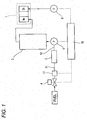
- Fig. 1 is a schematic diagram of a fuel cell power generation system of a first embodiment of the present invention
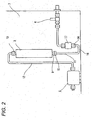
- Fig. 2 is a schematic diagram of a part of a body of the fuel cell power generation system of the first embodiment of the present invention in the vicinity of a desulfurizer.
- the fuel cell power generation system of the first embodiment includes: a fuel cell 1 configured to generate electric power by use of a fuel gas and an oxidant gas; a reformer 2 configured to subject a raw material, such as a natural gas, to steam reforming reaction, thereby producing a hydrogen-rich reformed gas; a desulfurizer 3 configured to eliminate a sulfur component from a raw gas serving as a raw material of the fuel gas containing hydrogen for power generation of the fuel cell 1 as a main component; a shutoff valve 4 configured to turn on or shut off a supply of the raw material; a booster pump 5 configured to increase the pressure of the raw gas, thereby supplying the raw gas to the reformer 2; an air blower 6 configured to supply air serving as an oxidant gas to the fuel cell 1; a flow sensor 17 disposed upstream from the desulfurizer 3 and configured to measure a flow rate of the raw material passing through the desulfurizer 3; a raw material pipe 11 that connects a desulfurizer inlet
- the controller 18 controls operation of the fuel cell power generation system, such as determining an amount of required air supplied to the fuel cell 1 according to a value of the flow rate detected by the flow sensor 17 and sending a control signal to the air blower 6.
- the shutoff valve 4, the flow sensor 17, the raw material pipe 11, the desulfurizer 3, a post-desulfurization pipe 12, the booster pump 5, the reformer 2 and the fuel cell 1 are connected in this order from an upstream side to a downstream side.
- the flow sensor 17 is disposed in the vicinity of a position immediately below the desulfurizer 3, and is connected to the desulfurizer 3 so as to communicate therewith by the raw material pipe 11 that is bent substantially in a J shape.
- the raw material pipe 11 has a raw material pipe inlet 14 that is opened upward and connected to the flow sensor 17 and a raw material pipe outlet 15 that is opened upward and connected to a desulfurizer inlet 9.
- the raw material pipe 11 is configured such that when the raw material pipe 11 is mounted to the fuel cell power generation system body 7, the raw material pipe inlet 14 connected to the flow sensor 17 is situated below the raw material pipe inlet 14 and above a trap portion 16 situated at a lowermost position of the raw material pipe 11.
- a raw material supplied from the shutoff valve 4 passes through the flow sensor 17, and a sulfur component of the raw material is eliminated by the desulfurizer 3. Subsequently, the raw material is pressurized by the booster pump 5 and supplied to the reformer 2. The raw gas is supplied to the fuel cell 1 as a hydrogen-rich fuel gas by the reforming unit 2. In the meantime, the controller 18 calculates an amount of air necessary for the fuel cell 1 according to the flow rate of raw material measured by the flow sensor 17 and sends the operation signal to the air blower 6. Reaction air serving as an oxidant gas is supplied from the air blower 6 to the fuel cell 1, whereby the fuel gas and the reaction air cause an electrochemical reaction, thereby generating electric power.
- the desulfurizer 3 eliminates sulfur contained in the raw material by use of an adsorbing phenomenon of a catalyst. Consequently, sulfur elimination capability of the desulfurizer 3 deteriorates in association with an increase in operating time. Accordingly, continuing use of the desulfurizer necessitates periodic replacement of the desulfurizer 3 with a new one. At the periodic replacement, the desulfurizer inlet 9 of the desulfurizer 3 is disconnected from the raw material pipe 11, and a desulfurizer outlet 10 is disconnected from the post-desulfurization pipe 12.
- a catalyst in the desulfurizer 3 is shaken by the microvibrations, and powder in the catalyst may come out of the desulfurizer inlet 9 provided on the lower surface of the desulfurizer 3 and enters the raw material pipe 11.
- the catalyst powder of a new desulfurizer 3 for replacement caused by transport vibrations may enter the raw material pipe 11. Further, airborne dust may enter the raw material pipe outlet 15 when the desulfurizer 3 is detached for replacement with a new desulfurizer 3.
- the catalyst powder or airborne dust entering the raw material pipe 11 is accumulated in the trap portion 16 provided at the lowest portion of the raw material pipe 11. Consequently, catalyst powder or airborne dust does not arrive at the flow sensor 17 located at an upper position with respect to the trap portion 16. Therefore, it is possible to prevent an operation failure of the flow sensor 17 caused by the entered catalyst powder or airborne dust.
- the fuel cell power generation system of the present embodiment includes: the desulfurizer 3 configured to eliminate a sulfur component from a raw gas serving as a raw material of a fuel gas containing hydrogen for power generation of the fuel cell 1 as a main component; the flow sensor 17 disposed upstream from the desulfurizer 3 and configured to measure a flow rate of raw gas passing through the desulfurizer 3; and the raw material pipe 11 having one end connected to a lower end of the desulfurizer 3 and another end connected to the flow sensor 17.
- the raw gas flows through an inside of the desulfurizer 3 in an upward direction, and the desulfurizer 3 is detachably connected to the raw material pipe 11.
- the desulfurizer 3 and the flow sensor 17 are disposed close to each other so as to be arranged side by side along a substantially vertical direction.
- the trap portion 16 configured to prevent arrival of the catalyst powder of the desulfurizer 3 or the dust entered from the one end of the raw material pipe 11 at the flow sensor 17 is disposed at a portion of the raw material pipe 11 between the one end thereof and the another end thereof.
- the trap portion 16 is configured such that side upstream from the trap portion 16 is situated above the trap portion 16.
- the trap portion 16 configured to prevent arrival of the catalyst powder of the desulfurizer 3 or dust entering from one end of the raw material pipe 11 at the flow sensor 17 is provided at a position of the raw material pipe 11 between the one end thereof and the another end thereof.
- the trap portion 16 may be formed such that side upstream from the trap portion 16 becomes higher than the trap portion 16. With this configuration, the trap portion 16 can readily be formed simply by bending the raw material pipe 11.
- the desulfurizer 3 is a part to be periodically replaced. Therefore, the desulfurizer 3 is disposed at a structural position to allow superior ease of maintenance. By disposing the flow sensor 17 in the vicinity of the position immediately below the desulfurizer 3, it becomes easy to check the flow sensor 3, whereby ease of maintenance of the flow sensor 3 is enhanced.
- the flow sensor 17 serves as an exemplified auxiliary device configured to communicate with the connection inlet provided on the lower surface of the desulfurizer 3 through the raw material pipe 11.
- another auxiliary device such as the shutoff valve 4 used in the fuel cell power generation system and a pressure sensor, is provided at the same structural location, it is also possible to prevent an operation failure of the auxiliary device caused by the catalyst powder or airborne dust.
- Fig. 3 is a perspective view of a raw material pipe used in a fuel cell power generation system of a second embodiment of the present invention
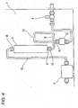
- Fig. 4 is a schematic diagram of a part of a body of the fuel cell power generation system of the embodiment in the vicinity of a desulfurizer.
- the raw material pipe 11 is bent into a loop shape along the vertical direction.
- the raw material pipe 11 includes the raw material pipe inlet 14 opened downward for a connection with the flow sensor 17, the raw material pipe outlet 15 opened upward in the vertical direction for a connection with the desulfurizer inlet 9, and the trap portion 16 serving as a lowermost portion of the loop portion of the raw material pipe 11.
- the flow sensor 17 is disposed in the vicinity of a position immediately below the desulfurizer 3, and is connected to the desulfurizer 3 so as to communicate therewith by the raw material pipe 11.
- the raw material pipe 11 bent in a loop shape along the vertical direction, instead of the raw material pipe 11 substantially bent in a J shape in the first embodiment.
- the second embodiment is structurally identical with the first embodiment.
- the catalyst in the desulfurizer 3 is shaken by the microvibrations, and catalyst powder may come out of the desulfurizer inlet 9 provided on the lower surface of the desulfurizer 3, to thus enter the raw material pipe 11.
- the catalyst powder of a new desulfurizer 3 for replacement caused by transport vibrations may enter the raw material pipe 11. Further, airborne dust may enter the raw material pipe outlet 15 when the desulfurizer 3 is detached for replacement with a new desulfurizer 3.
- the raw material pipe 11 is formed in a loop shape along the vertical direction, the entered catalyst powder or airborne dust is accumulated in the trap portion 16 provided at the lowermost portion of the loop portion of the raw material pipe 11 and does not arrive at the flow sensor 17. Consequently, it is possible to prevent an operation failure of the flow sensor 17 caused by the entered catalyst powder or airborne dust.
- the flow sensor 17 can readily be disposed in the vicinity of a position immediately below the desulfurizer 3. Since the desulfurizer 3 is a part to be periodically replaced, the desulfurizer 3 is disposed at a structural position to allow superior ease of maintenance. Consequently, the flow sensor 17 disposed in the vicinity of the position immediately below the desulfurizer 3 exhibits superior ease of maintenance.
- the flow sensor 17 is likely to be affected by pressure fluctuations caused by an increase of pressure of a raw material in the booster pump 5 communicating therewith. Nevertheless, the raw material pipe 11 is shaped to have a loop shape, which results in an increase in pipe length and a buffer space. Therefore, influence of pressure fluctuations in the booster pump 5 is lowered, and the accuracy of measurement of the flow sensor 17 is enhanced, whereby stable device operation can be realized.
- the loop shape of the raw material pipe 11 is one turn. However, the number of loops may be increased, which increases the buffer space and further lowers the influence of the booster pump 5.
- the raw material pipe 11 includes at least one loop portion in the vertical direction, and the lowermost portion of the loop portion of the raw material pipe 11 functions as the trap portion 16.
- the trap portion 16 located at the lowermost portion of the loop portion of the raw material pipe 11 and does not arrive at the flow sensor 17. Consequently, it is possible to prevent an operation failure of the flow sensor 17 caused by entered catalyst powder or airborne dust.
- the flow sensor 17 can easily be disposed in the vicinity of the position immediately below the desulfurizer 3.
- the flow sensor 17 serves as an exemplified auxiliary device configured to communicate with the connection inlet provided on the lower surface of the desulfurizer 3 through the raw material pipe 11.
- another auxiliary device such as the shutoff valve 4 used in the fuel cell power generation system and a pressure sensor, is provided at the same structural location, it is also prevent an operation failure of the auxiliary device caused by the catalyst powder or airborne dust.
- Fig. 5 is a schematic diagram of a part of a body of a fuel cell power generation system of a third embodiment of the present invention in the vicinity of the desulfurizer 3.
- the third embodiment is configured such that an inner diameter of the trap portion 16 is set greater than an inner diameter of a portion the raw material pipe 11 except the trap portion 16, in the fuel cell power generation system of the first embodiment.
- the third embodiment is structurally identical with the first embodiment.
- the catalyst in the desulfurizer 3 is shaken by the microvibrations, and catalyst powder may come out of from the desulfurizer inlet 9 provided on the lower surface of the desulfurizer 3, to thus enter the raw material pipe 11.
- the catalyst powder of a new desulfurizer 3 for replacement caused by transport vibrations may enter the raw material pipe 11. Further, airborne dust may enter the raw material pipe outlet 15 when the desulfurizer 3 is eliminated for replacement with a new desulfurizer 3.
- the raw material pipe 11 substantially bent in the J shape is used, and the inner diameter of the trap portion 16 situated at the lowermost portion of the raw material pipe 11 is set greater than the inner diameter of a portion of the raw material pipe 11 except the trap portion 16. Therefore, catalyst powder or airborne dust entering the raw material pipe 11 is accumulated in the trap portion 16 situated at the lowermost portion of the raw material pipe 11 and does not arrive at the flow sensor 17 disposed above the trap portion 16, whereby it is possible to prevent an operation failure of the flow sensor 17 caused by entered catalyst powder or airborne dust. Since the trap portion 16 has an inner diameter greater than the inner diameter of a portion of the raw material pipe 11 except the trap portion 16, even when the catalyst powder or airborne dust is accumulated in the trap portion 16, it hardly impedes a raw gas flow.
- the flow sensor 17 is likely to be affected by pressure fluctuations caused by an increase of pressure of the raw material in the booster pump 5 communicating therewith. Nevertheless, by increasing the inner diameter of the trap portion 16 situated at a portion of the raw material pipe 11 between the one end thereof and another end thereof, the inner volume of the trap portion 16 can be increased, and a buffer space can be increased. Therefore, influence of pressure fluctuations in the booster pump 5 is lowered, and the accuracy of measurement of the flow sensor 17 is enhanced, whereby stable device operation can be realized.
- the flow sensor 17 serves as an exemplified auxiliary device configured to communicate with the connection inlet provided on the lower surface of the desulfurizer 3 through the raw material pipe 11.
- another auxiliary device such as the shutoff valve 4 used in the fuel cell power generation system and a pressure sensor, is provided at the same structural location, it is also possible to prevent an operation failure of the auxiliary device caused by the catalyst powder or airborne dust.
- Fig. 6 is a schematic diagram of a part of a body of a fuel cell power generation system of a fourth embodiment of the present invention in the vicinity of the desulfurizer.
- the fuel cell power generation system of the fourth embodiment is configured such that in the fuel cell power generation system of the second embodiment, an inner diameter of the trap portion 16 is set greater than an inner diameter of a portion of the raw material pipe 11 except the trap portion 16.
- the third embodiment is structurally identical with the second embodiment.
- the catalyst in the desulfurizer 3 is shaken by the microvibrations, and catalyst powder may come out of the desulfurizer inlet 9 provided on the lower surface of the desulfurizer 3, to thus enter the raw material pipe 11.
- the catalyst powder of a new desulfurizer 3 for replacement caused by transport vibrations may enter the raw material pipe 11.
- airborne dust may enter the raw material pipe outlet 15 in a period during which the desulfurizer 3 is eliminated for replacement with a new desulfurizer 3.
- the raw material pipe 11 is bent in a loop shape in the vertical direction, and the inner diameter of the trap portion 16 situated at the lowermost portion of the loop portion of the raw material pipe 11 is set greater than the inner diameter of a portion the raw material pipe 11 except the trap portion 16.
- catalyst powder or airborne dust entering the raw material pipe 11 is accumulated in the trap portion 16 situated at the lowermost portion of the loop portion of the raw material pipe 11 and does not arrive at the flow sensor 17, whereby it is possible to prevent an operation failure of the flow sensor 17 caused by entered catalyst powder or airborne dust, Since the trap portion 16 has an inner diameter greater than the inner diameter of a portion of the raw material pipe 11 except the trap portion 16, even when the catalyst powder or airborne dust is accumulated in the trap portion 16, it hardly impedes a raw gas flow.
- the flow sensor 17 can readily be disposed in the vicinity of a position immediately below the desulfurizer 3. Since the desulfurizer 3 is a part to be periodically replaced, the desulfurizer 3 is disposed at a structural position to allow superior ease of maintenance. Consequently, the flow sensor 17 disposed in the vicinity of the position immediately below the desulfurizer 3 exhibits superior ease of maintenance.
- the flow sensor 17 is likely to be affected by pressure fluctuations caused by an increase of pressure of a raw material in the booster pump 5 communicating therewith. Nevertheless, by increasing the inner diameter of the trap portion 16 provided at a portion of the raw material pipe 11 between the one end thereof and another end thereof, the inner volume of the trap portion 16 can be increased, and the buffer space can also be increased. Therefore, influence of pressure fluctuations in the booster pump 5 is lowered, and the accuracy of measurement of the flow sensor 17 is enhanced, whereby stable device operation can be realized.
- the flow sensor 17 serves as an exemplified auxiliary device configured to communicate with the connection inlet provided on the lower surface of the desulfurizer 3 through the raw material pipe 11.
- another auxiliary device such as the shutoff valve 4 used in the fuel cell power generation system and a pressure sensor, is provided at the same structural location, it is also possible to prevent an operation failure of the auxiliary device caused by catalyst powder or airborne dust.
- Fig. 7 is a schematic diagram of a part of a body of a fuel cell power generation system of a fifth embodiment of the present invention in the vicinity of the desulfurizer 3.
- the fuel cell power generation system of the fifth embodiment is configured such that in the fuel cell power generation system of the first embodiment, a position of a downstream side of the flow sensor 17 is situated above a position of an upstream side of the desulfurizer 3..
- the fifth embodiment is structurally identical with the first embodiment.
- the position of the downstream side of the flow sensor 17 refers to a position of a side of a portion of the flow sensor 17 closer to the raw material pipe inlet 14 in Fig. 7 .
- the position of the upstream side of the desulfurizer 3 refers to a position of a side of the desulfurizer 3 closer to the raw material pipe outlet 15 in Fig. 7 .
- the catalyst in the desulfurizer 3 is shaken by the microvibrations, and catalyst powder may come out of the desulfurizer inlet 9 provided on the lower surface of the desulfurizer 3, to thus enter the raw material pipe 11.
- the catalyst powder of a new desulfurizer 3 for replacement caused by transport vibrations may enter the raw material pipe 11. Further, airborne dust may enter the raw material pipe outlet 15 when the desulfurizer 3 is eliminated for replacement with a new desulfurizer 3.
- the raw material pipe 11 substantially bent in the J shape is used, and the position of the downstream side of the flow sensor 17 is situated above the position of the upstream side of the desulfurizer 3. Consequently, positional energy resultant of fall of catalyst powder or airborne dust in the raw material pipe 11 is insufficient for the catalyst powder or airborne dust to pass through the trap portion 16 and arrive at the flow sensor 17 situated above the trap portion 16. Therefore, it is possible to prevent an operation failure of the flow sensor 17 caused by entered catalyst powder or airborne dust.
- the flow sensor 17 serves as an exemplified auxiliary device configured to communicate with the connection inlet provided on the lower surface of the desulfurizer 3 through the raw material pipe 11.
- another auxiliary device such as the shutoff valve 4 used in the fuel cell power generation system and a pressure sensor, is provided at the same structural location, it is also possible to prevent an operation failure of the auxiliary device caused by the catalyst powder or airborne dust.
- the trap portion 16 in the raw material pipe 11 shown in Fig. 7 may be configured such that an inner diameter thereof is set larger than an inner diameter of a portion of the raw material pipe .11 except the trap portion 16, such as the trap portion 16 shown in Fig. 5 .
- positional energy resultant of fall of catalyst powder or airborne dust in the raw material pipe 11 is insufficient for the catalyst powder or airborne dust to pass through the trap portion 16 and arrive at the flow sensor 17 situated above the trap portion 16. Consequently, it is possible to prevent an operation failure of the flow sensor 17 caused by entered catalyst powder or airborne dust.
- the flow sensor 17 is likely to be affected by pressure fluctuations caused by an increase of pressure of a raw material in the booster pump 5 communicating therewith.
- the inner diameter of the trap portion 16 provided at a portion of the raw material pipe 11 between one end thereof and another end thereof, the inner volume of the trap portion 16 can be increased, and the buffer space can also be increased. Therefore, influence of pressure fluctuations in the booster pump 5 is lowered, and the accuracy of measurement of the flow sensor 17 is enhanced, whereby stable device operation can be realized.
- the trap portion prevents catalyst powder of the desulfurizer or airborne dust, which enters in the raw material pipe 11, from entering the flow sensor. Therefore, it is possible to prevent an operation failure of the flow sensor caused by entry of catalyst powder or airborne dust, whereby operation reliability of the flow sensor can be enhanced. Consequently, the present invention is useful for a fuel cell power generation system for home use in which a desulfurizer is connected to an auxiliary device used in the fuel cell power generation system, such as a flow sensor located below the desulfurizer, by a raw material pipe, and in which the desulfurizer is to be periodically replaced.
Landscapes
- Chemical & Material Sciences (AREA)
- Chemical Kinetics & Catalysis (AREA)
- Engineering & Computer Science (AREA)
- General Chemical & Material Sciences (AREA)
- Sustainable Energy (AREA)
- Sustainable Development (AREA)
- Manufacturing & Machinery (AREA)
- Electrochemistry (AREA)
- Life Sciences & Earth Sciences (AREA)
- Organic Chemistry (AREA)
- Health & Medical Sciences (AREA)
- General Health & Medical Sciences (AREA)
- Combustion & Propulsion (AREA)
- Inorganic Chemistry (AREA)
- Fuel Cell (AREA)
- Hydrogen, Water And Hydrids (AREA)
Claims (7)
- Brennstoffzellenstromerzeugungssystem, umfassend:einen Entschwefler (3), der dazu konfiguriert ist, eine Schwefelkomponente aus einem Rohgas zu eliminieren, das als Rohstoff für ein Brenngas dient, welches Wasserstoff zur Stromerzeugung in einer Brennstoffzelle als Hauptkomponente enthält;eine Hilfseinrichtung (4, 17), die aus einem Durchflusssensor (17), einem Absperrventil (4) und einem Drucksensor gewählt wird und stromaufwärts vor dem Entschwefler (3) angeordnet ist; undein Rohstoffrohr (11) dessen eines Ende mit einer vorderen Seite des Entschweflers (3) verbunden ist und dessen anderes Ende mit der Hilfseinrichtung (4, 17) verbunden ist,wobei das Rohgas durch eine Innenseite des Entschweflers (3) fließt,wobei der Entschwefler (3) lösbar mit dem Rohstoffrohr (11) verbunden ist,wobei ein Auffangabschnitt (16), der dazu konfiguriert ist, Katalysatorpulver des Entschweflers (3) oder Staub aufzufangen, der von dem einen Ende des Rohstoffrohrs (11) eintritt, an einem Abschnitt des Rohstoffrohrs (11) zwischen dessen einem Ende und dessen anderem Ende angeordnet ist, undwobei das Rohstoffrohr (11) in einer J-Form konfiguriert ist, so dass der Auffangabschnitt (16) an einer untersten Position des Rohstoffrohrs (11) angeordnet ist.
- Brennstoffzellenstromerzeugungssystem, umfassend:einen Entschwefler (3), der dazu konfiguriert ist, eine Schwefelkomponente aus einem Rohgas zu eliminieren, das als Rohstoff für ein Brenngas dient, welches Wasserstoff zur Stromerzeugung in einer Brennstoffzelle als Hauptkomponente enthält;eine Hilfseinrichtung (4, 17), die aus einem Durchflusssensor (17), einem Absperrventil (4) und einem Drucksensor gewählt wird und stromaufwärts vor dem Entschwefler (3) angeordnet ist; undein Rohstoffrohr (11) dessen eines Ende mit einer vorderen Seite des Entschweflers (3) verbunden ist und dessen anderes Ende mit der Hilfseinrichtung (4, 17) verbunden ist,wobei das Rohgas durch eine Innenseite des Entschweflers (3) fließt,wobei der Entschwefler (3) lösbar mit dem Rohstoffrohr (11) verbunden ist,wobei ein Auffangabschnitt (16), der dazu konfiguriert ist, Katalysatorpulver des Entschweflers (3) oder Staub aufzufangen, der von dem einen Ende des Rohstoffrohrs (11) eintritt, an einem Abschnitt des Rohstoffrohrs (11) zwischen dessen einem Ende und dessen anderem Ende angeordnet ist, unddas Rohrstoffrohr (11) mindestens einen Schleifenabschnitt in vertikaler Richtung umfasst, so dass der Auffangabschnitt (16) als ein unterster Abschnitt des Schleifenabschnitts dient.
- Brennstoffzellenstromerzeugungssystem nach Anspruch 1 oder 2,
wobei die stromaufwärts befindliche Seite des Entschweflers (3) unterhalb einer stromabwärts befindlichen Seite des Entschwefler (3) angeordnet ist. - Brennstoffzellenstromerzeugungssystem nach einem der Ansprüche 1 bis 3,
wobei eine Seite, die sich stromaufwärts von dem Auffangabschnitt befindet, oberhalb des Auffangabschnitts angeordnet ist. - Brennstoffzellenstromerzeugungssystem nach einem der Ansprüche 1 bis 4,
wobei der Entschwefler (3) und die Hilfseinrichtung (4, 17) nahe beieinander liegen, so dass sie im Wesentlichen entlang einer vertikalen Richtung Seite an Seite angeordnet sind. - Brennstoffzellenstromerzeugungssystem nach einem der Ansprüche 1, 3 oder 4,
wobei sich eine Position einer stromabwärts liegenden Seite der Hilfseinrichtung (4, 17) oberhalb einer Position der stromaufwärts liegenden Seite des Entschweflers (3) befindet. - Brennstoffzellenstromerzeugungssystem nach einem der Ansprüche 1 bis 6,
wobei der Auffangabschnitt (16) einen größeren Innendurchmesser als ein Innendurchmesser eines Abschnitts des Rohstoffrohrs (11) mit Ausnahme des Auffangabschnitts aufweist.
Applications Claiming Priority (2)
| Application Number | Priority Date | Filing Date | Title |
|---|---|---|---|
| JP2009096860 | 2009-04-13 | ||
| PCT/JP2010/001066 WO2010119601A1 (ja) | 2009-04-13 | 2010-02-18 | 燃料電池発電システム |
Publications (4)
| Publication Number | Publication Date |
|---|---|
| EP2421079A1 EP2421079A1 (de) | 2012-02-22 |
| EP2421079A8 EP2421079A8 (de) | 2012-06-27 |
| EP2421079A4 EP2421079A4 (de) | 2013-02-20 |
| EP2421079B1 true EP2421079B1 (de) | 2015-06-24 |
Family
ID=42982276
Family Applications (1)
| Application Number | Title | Priority Date | Filing Date |
|---|---|---|---|
| EP10764188.8A Active EP2421079B1 (de) | 2009-04-13 | 2010-02-18 | Brennstoffzellenerzeugungssystem |
Country Status (3)
| Country | Link |
|---|---|
| EP (1) | EP2421079B1 (de) |
| JP (1) | JP5483295B2 (de) |
| WO (1) | WO2010119601A1 (de) |
Family Cites Families (11)
| Publication number | Priority date | Publication date | Assignee | Title |
|---|---|---|---|---|
| JP2650666B2 (ja) * | 1992-08-04 | 1997-09-03 | 三菱電機株式会社 | 脱硫装置およびその触媒の交換方法 |
| US6635372B2 (en) * | 2001-10-01 | 2003-10-21 | General Motors Corporation | Method of delivering fuel and air to a fuel cell system |
| JP2005268043A (ja) * | 2004-03-18 | 2005-09-29 | Aisin Seiki Co Ltd | 燃料電池システム |
| JP2006260874A (ja) * | 2005-03-16 | 2006-09-28 | Ishikawajima Harima Heavy Ind Co Ltd | 固体高分子型燃料電池発電装置用燃料ガス供給装置 |
| JP4507955B2 (ja) * | 2005-04-05 | 2010-07-21 | トヨタ自動車株式会社 | 水素生成装置及び燃料電池システム |
| JP2007084621A (ja) * | 2005-09-20 | 2007-04-05 | Hagio Koatsu Yoki Kk | 脱硫剤カートリッジ |
| JP2006140164A (ja) | 2006-01-11 | 2006-06-01 | Toshiba Home Technology Corp | 燃料電池装置 |
| JP2008258023A (ja) * | 2007-04-05 | 2008-10-23 | Honda Motor Co Ltd | パッケージ型燃料電池 |
| JP2008282572A (ja) | 2007-05-08 | 2008-11-20 | Toshiba Corp | 燃料電池システム |
| JP4989340B2 (ja) * | 2007-07-19 | 2012-08-01 | アイシン精機株式会社 | 改質原料供給システム |
| JP5242986B2 (ja) | 2007-10-16 | 2013-07-24 | 三菱レイヨン株式会社 | 熱可塑性樹脂組成物およびその製造方法 |
-
2010
- 2010-02-18 JP JP2011509180A patent/JP5483295B2/ja active Active
- 2010-02-18 EP EP10764188.8A patent/EP2421079B1/de active Active
- 2010-02-18 WO PCT/JP2010/001066 patent/WO2010119601A1/ja not_active Ceased
Also Published As
| Publication number | Publication date |
|---|---|
| EP2421079A1 (de) | 2012-02-22 |
| JP5483295B2 (ja) | 2014-05-07 |
| EP2421079A4 (de) | 2013-02-20 |
| EP2421079A8 (de) | 2012-06-27 |
| JPWO2010119601A1 (ja) | 2012-10-22 |
| WO2010119601A1 (ja) | 2010-10-21 |
Similar Documents
| Publication | Publication Date | Title |
|---|---|---|
| CN101222061B (zh) | 对流转换式燃料电池系统中的氮分数的控制 | |
| KR101199133B1 (ko) | 연료전지 시스템 및 그 운전 방법 | |
| US20090117420A1 (en) | Method for judging system condition in fuel cell system | |
| US20100183939A1 (en) | Fuel cell system | |
| US9029037B2 (en) | Fuel cell system with a liquid separator | |
| US20090081492A1 (en) | Fuel Cell System, Moving Object Equipped With Fuel Cell System, and Abnormality Judgement Method For Fuel Cell System | |
| US7368192B2 (en) | Method and apparatus for hydrogen detection and dilution | |
| MY151475A (en) | Hydrogen-producing fuel cell systems with load-responsive feedstock delivery systems | |
| JPWO2007013453A1 (ja) | 燃料電池システム | |
| CN101490887A (zh) | 燃料电池系统 | |
| EP2769958B1 (de) | Verfahren zum betreiben einer wasserstofferzeugungsvorrichtung | |
| EP2421079A1 (de) | Brennstoffzellenerzeugungssystem | |
| JP4989340B2 (ja) | 改質原料供給システム | |
| US20100261093A1 (en) | Fuel cell system | |
| JP5861300B2 (ja) | 燃料電池システム | |
| JP2009032406A (ja) | 燃料電池装置 | |
| CN117730169A (zh) | 用于运行电解设施的方法和电解设施 | |
| EP1635414A1 (de) | Brennstoffzellensystem | |
| JP4831973B2 (ja) | 燃料電池システム | |
| KR102475163B1 (ko) | 수소 이송관에서 수분제거장치 | |
| JP2017137939A (ja) | ガス充填システム | |
| JP2007026808A (ja) | 燃料電池システム | |
| JP2014172780A (ja) | 水素生成装置および燃料電池システム | |
| JP2008292356A (ja) | ガス検出装置 | |
| JP2003217640A (ja) | 燃料電池発電システム |
Legal Events
| Date | Code | Title | Description |
|---|---|---|---|
| PUAI | Public reference made under article 153(3) epc to a published international application that has entered the european phase |
Free format text: ORIGINAL CODE: 0009012 |
|
| 17P | Request for examination filed |
Effective date: 20110207 |
|
| AK | Designated contracting states |
Kind code of ref document: A1 Designated state(s): AT BE BG CH CY CZ DE DK EE ES FI FR GB GR HR HU IE IS IT LI LT LU LV MC MK MT NL NO PL PT RO SE SI SK SM TR |
|
| RIN1 | Information on inventor provided before grant (corrected) |
Inventor name: SANO, HIDEHARU Inventor name: TAGUCHI, KIYOSHI |
|
| DAX | Request for extension of the european patent (deleted) | ||
| A4 | Supplementary search report drawn up and despatched |
Effective date: 20130121 |
|
| RIC1 | Information provided on ipc code assigned before grant |
Ipc: C01B 3/38 20060101ALI20130115BHEP Ipc: H01M 8/04 20060101AFI20130115BHEP |
|
| 17Q | First examination report despatched |
Effective date: 20140114 |
|
| RIC1 | Information provided on ipc code assigned before grant |
Ipc: C01B 3/34 20060101ALI20141103BHEP Ipc: H01M 8/04 20060101AFI20141103BHEP Ipc: H01M 8/06 20060101ALI20141103BHEP |
|
| GRAP | Despatch of communication of intention to grant a patent |
Free format text: ORIGINAL CODE: EPIDOSNIGR1 |
|
| INTG | Intention to grant announced |
Effective date: 20150112 |
|
| RAP1 | Party data changed (applicant data changed or rights of an application transferred) |
Owner name: PANASONIC INTELLECTUAL PROPERTY MANAGEMENT CO., LT |
|
| GRAS | Grant fee paid |
Free format text: ORIGINAL CODE: EPIDOSNIGR3 |
|
| GRAA | (expected) grant |
Free format text: ORIGINAL CODE: 0009210 |
|
| AK | Designated contracting states |
Kind code of ref document: B1 Designated state(s): AT BE BG CH CY CZ DE DK EE ES FI FR GB GR HR HU IE IS IT LI LT LU LV MC MK MT NL NO PL PT RO SE SI SK SM TR |
|
| REG | Reference to a national code |
Ref country code: GB Ref legal event code: FG4D |
|
| REG | Reference to a national code |
Ref country code: CH Ref legal event code: EP |
|
| REG | Reference to a national code |
Ref country code: AT Ref legal event code: REF Ref document number: 733265 Country of ref document: AT Kind code of ref document: T Effective date: 20150715 |
|
| REG | Reference to a national code |
Ref country code: IE Ref legal event code: FG4D |
|
| REG | Reference to a national code |
Ref country code: DE Ref legal event code: R096 Ref document number: 602010025445 Country of ref document: DE |
|
| PG25 | Lapsed in a contracting state [announced via postgrant information from national office to epo] |
Ref country code: LT Free format text: LAPSE BECAUSE OF FAILURE TO SUBMIT A TRANSLATION OF THE DESCRIPTION OR TO PAY THE FEE WITHIN THE PRESCRIBED TIME-LIMIT Effective date: 20150624 Ref country code: NO Free format text: LAPSE BECAUSE OF FAILURE TO SUBMIT A TRANSLATION OF THE DESCRIPTION OR TO PAY THE FEE WITHIN THE PRESCRIBED TIME-LIMIT Effective date: 20150924 Ref country code: FI Free format text: LAPSE BECAUSE OF FAILURE TO SUBMIT A TRANSLATION OF THE DESCRIPTION OR TO PAY THE FEE WITHIN THE PRESCRIBED TIME-LIMIT Effective date: 20150624 Ref country code: HR Free format text: LAPSE BECAUSE OF FAILURE TO SUBMIT A TRANSLATION OF THE DESCRIPTION OR TO PAY THE FEE WITHIN THE PRESCRIBED TIME-LIMIT Effective date: 20150624 |
|
| REG | Reference to a national code |
Ref country code: AT Ref legal event code: MK05 Ref document number: 733265 Country of ref document: AT Kind code of ref document: T Effective date: 20150624 |
|
| REG | Reference to a national code |
Ref country code: LT Ref legal event code: MG4D |
|
| PG25 | Lapsed in a contracting state [announced via postgrant information from national office to epo] |
Ref country code: GR Free format text: LAPSE BECAUSE OF FAILURE TO SUBMIT A TRANSLATION OF THE DESCRIPTION OR TO PAY THE FEE WITHIN THE PRESCRIBED TIME-LIMIT Effective date: 20150925 Ref country code: LV Free format text: LAPSE BECAUSE OF FAILURE TO SUBMIT A TRANSLATION OF THE DESCRIPTION OR TO PAY THE FEE WITHIN THE PRESCRIBED TIME-LIMIT Effective date: 20150624 Ref country code: BG Free format text: LAPSE BECAUSE OF FAILURE TO SUBMIT A TRANSLATION OF THE DESCRIPTION OR TO PAY THE FEE WITHIN THE PRESCRIBED TIME-LIMIT Effective date: 20150924 |
|
| REG | Reference to a national code |
Ref country code: NL Ref legal event code: MP Effective date: 20150624 |
|
| PG25 | Lapsed in a contracting state [announced via postgrant information from national office to epo] |
Ref country code: EE Free format text: LAPSE BECAUSE OF FAILURE TO SUBMIT A TRANSLATION OF THE DESCRIPTION OR TO PAY THE FEE WITHIN THE PRESCRIBED TIME-LIMIT Effective date: 20150624 |
|
| REG | Reference to a national code |
Ref country code: FR Ref legal event code: PLFP Year of fee payment: 7 |
|
| PG25 | Lapsed in a contracting state [announced via postgrant information from national office to epo] |
Ref country code: IS Free format text: LAPSE BECAUSE OF FAILURE TO SUBMIT A TRANSLATION OF THE DESCRIPTION OR TO PAY THE FEE WITHIN THE PRESCRIBED TIME-LIMIT Effective date: 20151024 Ref country code: CZ Free format text: LAPSE BECAUSE OF FAILURE TO SUBMIT A TRANSLATION OF THE DESCRIPTION OR TO PAY THE FEE WITHIN THE PRESCRIBED TIME-LIMIT Effective date: 20150624 Ref country code: RO Free format text: LAPSE BECAUSE OF NON-PAYMENT OF DUE FEES Effective date: 20150624 Ref country code: PT Free format text: LAPSE BECAUSE OF FAILURE TO SUBMIT A TRANSLATION OF THE DESCRIPTION OR TO PAY THE FEE WITHIN THE PRESCRIBED TIME-LIMIT Effective date: 20151026 Ref country code: SK Free format text: LAPSE BECAUSE OF FAILURE TO SUBMIT A TRANSLATION OF THE DESCRIPTION OR TO PAY THE FEE WITHIN THE PRESCRIBED TIME-LIMIT Effective date: 20150624 Ref country code: AT Free format text: LAPSE BECAUSE OF FAILURE TO SUBMIT A TRANSLATION OF THE DESCRIPTION OR TO PAY THE FEE WITHIN THE PRESCRIBED TIME-LIMIT Effective date: 20150624 Ref country code: ES Free format text: LAPSE BECAUSE OF FAILURE TO SUBMIT A TRANSLATION OF THE DESCRIPTION OR TO PAY THE FEE WITHIN THE PRESCRIBED TIME-LIMIT Effective date: 20150624 Ref country code: PL Free format text: LAPSE BECAUSE OF FAILURE TO SUBMIT A TRANSLATION OF THE DESCRIPTION OR TO PAY THE FEE WITHIN THE PRESCRIBED TIME-LIMIT Effective date: 20150624 |
|
| REG | Reference to a national code |
Ref country code: DE Ref legal event code: R097 Ref document number: 602010025445 Country of ref document: DE |
|
| PG25 | Lapsed in a contracting state [announced via postgrant information from national office to epo] |
Ref country code: IT Free format text: LAPSE BECAUSE OF FAILURE TO SUBMIT A TRANSLATION OF THE DESCRIPTION OR TO PAY THE FEE WITHIN THE PRESCRIBED TIME-LIMIT Effective date: 20150624 Ref country code: DK Free format text: LAPSE BECAUSE OF FAILURE TO SUBMIT A TRANSLATION OF THE DESCRIPTION OR TO PAY THE FEE WITHIN THE PRESCRIBED TIME-LIMIT Effective date: 20150624 |
|
| PLBE | No opposition filed within time limit |
Free format text: ORIGINAL CODE: 0009261 |
|
| STAA | Information on the status of an ep patent application or granted ep patent |
Free format text: STATUS: NO OPPOSITION FILED WITHIN TIME LIMIT |
|
| PG25 | Lapsed in a contracting state [announced via postgrant information from national office to epo] |
Ref country code: BE Free format text: LAPSE BECAUSE OF NON-PAYMENT OF DUE FEES Effective date: 20160229 |
|
| 26N | No opposition filed |
Effective date: 20160329 |
|
| PG25 | Lapsed in a contracting state [announced via postgrant information from national office to epo] |
Ref country code: SI Free format text: LAPSE BECAUSE OF FAILURE TO SUBMIT A TRANSLATION OF THE DESCRIPTION OR TO PAY THE FEE WITHIN THE PRESCRIBED TIME-LIMIT Effective date: 20150624 |
|
| PG25 | Lapsed in a contracting state [announced via postgrant information from national office to epo] |
Ref country code: MC Free format text: LAPSE BECAUSE OF FAILURE TO SUBMIT A TRANSLATION OF THE DESCRIPTION OR TO PAY THE FEE WITHIN THE PRESCRIBED TIME-LIMIT Effective date: 20150624 Ref country code: LU Free format text: LAPSE BECAUSE OF FAILURE TO SUBMIT A TRANSLATION OF THE DESCRIPTION OR TO PAY THE FEE WITHIN THE PRESCRIBED TIME-LIMIT Effective date: 20160218 |
|
| REG | Reference to a national code |
Ref country code: CH Ref legal event code: PL |
|
| PG25 | Lapsed in a contracting state [announced via postgrant information from national office to epo] |
Ref country code: CH Free format text: LAPSE BECAUSE OF NON-PAYMENT OF DUE FEES Effective date: 20160229 Ref country code: LI Free format text: LAPSE BECAUSE OF NON-PAYMENT OF DUE FEES Effective date: 20160229 |
|
| REG | Reference to a national code |
Ref country code: IE Ref legal event code: MM4A |
|
| PG25 | Lapsed in a contracting state [announced via postgrant information from national office to epo] |
Ref country code: BE Free format text: LAPSE BECAUSE OF FAILURE TO SUBMIT A TRANSLATION OF THE DESCRIPTION OR TO PAY THE FEE WITHIN THE PRESCRIBED TIME-LIMIT Effective date: 20150624 |
|
| PG25 | Lapsed in a contracting state [announced via postgrant information from national office to epo] |
Ref country code: IE Free format text: LAPSE BECAUSE OF NON-PAYMENT OF DUE FEES Effective date: 20160218 |
|
| REG | Reference to a national code |
Ref country code: FR Ref legal event code: PLFP Year of fee payment: 8 |
|
| PG25 | Lapsed in a contracting state [announced via postgrant information from national office to epo] |
Ref country code: SE Free format text: LAPSE BECAUSE OF FAILURE TO SUBMIT A TRANSLATION OF THE DESCRIPTION OR TO PAY THE FEE WITHIN THE PRESCRIBED TIME-LIMIT Effective date: 20150624 Ref country code: NL Free format text: LAPSE BECAUSE OF FAILURE TO SUBMIT A TRANSLATION OF THE DESCRIPTION OR TO PAY THE FEE WITHIN THE PRESCRIBED TIME-LIMIT Effective date: 20150624 |
|
| PG25 | Lapsed in a contracting state [announced via postgrant information from national office to epo] |
Ref country code: MT Free format text: LAPSE BECAUSE OF FAILURE TO SUBMIT A TRANSLATION OF THE DESCRIPTION OR TO PAY THE FEE WITHIN THE PRESCRIBED TIME-LIMIT Effective date: 20150624 |
|
| REG | Reference to a national code |
Ref country code: FR Ref legal event code: PLFP Year of fee payment: 9 |
|
| PG25 | Lapsed in a contracting state [announced via postgrant information from national office to epo] |
Ref country code: HU Free format text: LAPSE BECAUSE OF FAILURE TO SUBMIT A TRANSLATION OF THE DESCRIPTION OR TO PAY THE FEE WITHIN THE PRESCRIBED TIME-LIMIT; INVALID AB INITIO Effective date: 20100218 Ref country code: CY Free format text: LAPSE BECAUSE OF FAILURE TO SUBMIT A TRANSLATION OF THE DESCRIPTION OR TO PAY THE FEE WITHIN THE PRESCRIBED TIME-LIMIT Effective date: 20150624 Ref country code: SM Free format text: LAPSE BECAUSE OF FAILURE TO SUBMIT A TRANSLATION OF THE DESCRIPTION OR TO PAY THE FEE WITHIN THE PRESCRIBED TIME-LIMIT Effective date: 20150624 |
|
| PG25 | Lapsed in a contracting state [announced via postgrant information from national office to epo] |
Ref country code: MK Free format text: LAPSE BECAUSE OF FAILURE TO SUBMIT A TRANSLATION OF THE DESCRIPTION OR TO PAY THE FEE WITHIN THE PRESCRIBED TIME-LIMIT Effective date: 20150624 Ref country code: MT Free format text: LAPSE BECAUSE OF FAILURE TO SUBMIT A TRANSLATION OF THE DESCRIPTION OR TO PAY THE FEE WITHIN THE PRESCRIBED TIME-LIMIT Effective date: 20160229 Ref country code: TR Free format text: LAPSE BECAUSE OF FAILURE TO SUBMIT A TRANSLATION OF THE DESCRIPTION OR TO PAY THE FEE WITHIN THE PRESCRIBED TIME-LIMIT Effective date: 20150624 |
|
| PGFP | Annual fee paid to national office [announced via postgrant information from national office to epo] |
Ref country code: DE Payment date: 20250218 Year of fee payment: 16 |
|
| PGFP | Annual fee paid to national office [announced via postgrant information from national office to epo] |
Ref country code: FR Payment date: 20250221 Year of fee payment: 16 |
|
| PGFP | Annual fee paid to national office [announced via postgrant information from national office to epo] |
Ref country code: GB Payment date: 20250219 Year of fee payment: 16 |