Connecting Structure for Relay Terminal
-
The present invention relates to a connecting structure for relay terminal.
-
For example, devices such as a motor fixed to an engine and an inverter are mounted in a hybrid vehicle. This motor is connected to the inverter by a wiring harness such as a power cable.
-
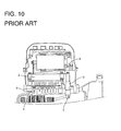
There has been known a structure in which a motor 1 and an inverter 2 are untied for space saving and electrically connected by relay terminals 3 as shown in
FIG. 10 (see Japanese Unexamined Patent Publication No.
2004-215355 ). These relay terminals 3 are in the form of straight bars and directly connect three motor side terminals 5 provided on the motor 1 and three inverter side terminals 6 provided on the inverter 2. In this way, a wiring harness for connecting the motor 1 and the inverter 2 can be omitted.
-
However, the motor 1 is fixed to an engine and vibration from the engine is directly transmitted to the relay terminal 3 via the motor 1 and, in addition, vibration generated from the inverter 2 is directly transmitted to the relay terminals 3. Since the vibration from the engine and that from the inverter 2 have different frequencies, the vibrations having different frequencies are simultaneously transmitted to the relay terminals 3. Thus, at or near the natural frequency of the relay terminals 3, resonance occurs and metal fatigue progresses, whereby there is a problem of crack and cut.
-
The present invention was developed in view of the above situation and an object thereof is to improve lifetime of a relay terminal.
-
This object is solved according to the invention by the features of the independent claim. Particular embodiments of the invention are subject of the dependent claims.
-
Accordingly, the lifetime of a relay terminal is improved by suppressing damage of a relay terminal due to metal fatigue by absorbing vibrations transmitted from devices.
-
According to the invention, there is provided a connecting structure for a relay terminal made of an enameled wire and adapted to electrically connect a first device side terminal provided on a first device and a second device side terminal provided on a second device, wherein the relay terminal comprises: a first connecting portion to be connected to the first device side terminal; a second connecting portion to be connected to the second device side terminal; and at least one vibration absorbing portion electrically conductively connecting the first and second connecting portions and having a wound configuration.
-
The present invention is preferably embodied to have the following constructions.
-
The vibration absorbing portion may be spirally wound about a line connecting the first and second connecting portions as an axial center.
-
According to a particular embodiment there is provided, a connecting structure for a relay terminal made of an enameled wire and adapted to electrically connect a first device side terminal provided on a first device and a second device side terminal provided on a second device, wherein the relay terminal comprises a first connecting portion to be connected to the first device side terminal; a second connecting portion to be connected to the second device side terminal; and a vibration absorbing portion electrically conductively connecting the first and second connecting portions and spirally wound about a line connecting the first and second connecting portions as an axial center.
-
According to the relay terminal connecting structure constructed as described above, damage of the relay terminal due to metal fatigue can be suppressed by absorbing vibrations transmitted to the relay terminal from the first device side terminal and the second device side terminal by the spirally wound vibration absorbing portion.
-
A plurality of relay terminals may be provided and so arranged that the positions of the axial centers of the respective vibration absorbing portions substantially are aligned.
-
According to this construction, for example, by arranging the plurality of vibration absorbing portions in series in a vertical direction to substantially align the positions of the axial centers of the respective vibration absorbing portions, an area taken up by the vibration absorbing portions can be reduced in a lateral direction as compared with the case where the vibration absorbing portions are juxtaposed in the lateral direction.
-
The vibration absorbing portion may be or comprise at least one coil spring extending in a direction of the axial center of the vibration absorbing portion.
-
According to this construction, vibrations transmitted from the first and second devices can be absorbed by resilient deformation of the coil spring in the direction of the axial center. This enables damage of the relay terminal due to metal fatigue to be suppressed.
-
The enamel wires may be arranged at intervals in a circumferential direction about the axial centers of the vibration absorbing portion (particularly the coil springs) in a cross section of the vibration absorbing portion (particularly the coil springs) perpendicular to the direction of the axial centers.
-
According to this construction, for example, in the case of including three relay terminals, three coil springs are spirally wound together. This enables an area taken up by the coil springs to be more reduced in the vertical direction as compared with the case where the coil springs are arranged in series in the vertical direction.
-
The first device may be or comprise a three-phase motor fixed to an engine, the first device side terminal may be three motor side terminals provided on the three-phase motor, the second device may be or comprise an inverter and the second device side terminal may be three inverter side terminals provided on the inverter; and corresponding pairs of the three motor side terminals and the three inverter side terminals may be individually connected by three relay terminals.
-
According to this construction, the relay terminals of the present invention can be applied for connection of the three-phase motor and the inverter having different vibration frequencies.
-
The first connecting portion may be provided to be fastened to the first device side terminal and fixed to a portion of a terminal block particularly by at least partly inserting a fastening bolt through a bolt insertion hole of the first device side terminal and the inside of the first connecting portion and tightening the fastening bolt to the terminal block and/or the second connecting portion may be provided to be fastened to the second device side terminal and fixed to a portion of the terminal block particularly by at least partly inserting a fastening bolt through a bolt insertion hole of the second device side terminal and the inside of the second connecting portion and tightening the fastening bolt to the terminal block.
-
The vibration absorbing portion may be arranged near a side surface of a terminal block.
-
The first connecting portion may include a first relay wire which is bent at an angle different from 0° or 180°, preferably substantially perpendicularly or upward after substantially extending straight up to a side surface of a terminal block and/or the second connecting portion may include a second side relay wire which is bent at an angle different from 0° or 180°, preferably substantially perpendicularly or downward after substantially extending straight up to the side surface of the terminal block.
-
The vibration absorbing portion is at least partly covered by a protection cover.
-
The protection cover may be mounted to a terminal block by one or more tapping screws are at least partly inserted through one or more respective mounting pieces.
-
At least one slit may be formed in the protection cover, through which at least one respective first relay wire extending from the first connecting portion is to be inserted into the protection cover.
-
The slit may be so dimensioned that small clearances are formed between the first relay wire and an edge portion of the slit in a state where the first relay wire extending from the first connecting portion are inserted
-
The vibration absorbing portion may comprise two or more coil springs which are spirally wound together with the positions of axial centers thereof substantially aligned to have a plural spiral structure.
-
The two or more coil springs may substantially have the same diameter.
-
Accordingly, it is possible to suppress damage of a relay terminal due to metal fatigue by absorbing vibrations transmitted from devices.
-
These and other objects, features and advantages of the present invention will become more apparent upon reading of the following detailed description of preferred embodiments and accompanying drawings. It should be understood that even though embodiments are separately described, single features thereof may be combined to additional embodiments.
- FIG. 1 is a front view with a protection cover partly in section showing a state where three relay terminals according to a first embodiment are juxtaposed between a motor and an inverter,
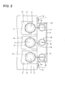
- FIG. 2 is a plan view showing the state where the three relay terminals according to the first embodiment are juxtaposed between the motor and the inverter, FIG. 3 is a bottom view of the state of FIG. 2,
- FIG. 4 is a side view with the protection cover partly in section showing a state where the relay terminals according to the first embodiment are arranged between the motor and the inverter,
- FIG. 5 is a front view with a protection cover partly in section showing a state where relay terminals according to a second embodiment are arranged between a motor and an inverter,
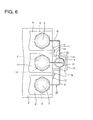
- FIG. 6 is a plan view showing the state where the relay terminals according to the second embodiment are arranged between the motor and the inverter,
- FIG. 7 is a bottom view showing the state of FIG. 6,
- FIG. 8 is a side view with the protection cover partly in section showing the state where the relay terminals according to the second embodiment are arranged between the motor and the inverter,
- FIG. 9 is a section enlargedly showing coil spring parts of FIG. 6 cut in a direction perpendicular to a direction of axial centers, and
- FIG. 10 is a partial section showing a relay terminal mounting structure according to a prior art.
<First Embodiment>
-
Hereinafter, a first specific embodiment of the present invention is described with reference to FIGS. 1 to 4.
-
In this embodiment is illustrated a connecting structure for relay terminals 10 for electrically connecting a motor (corresponding to a particular "first device") 50 fixed or mountable to an unillustrated engine and an inverter (corresponding to a particular "second device") 60, the connecting structure particularly being used in a vehicle such as a hybrid vehicle or an electric vehicle.
-
The motor 50 and the inverter 60 particularly are at least partly housed in the same case, which is not shown, and/or at least partly partitioned by an unillustrated partition wall. Further, the motor 50 particularly is used in the housing with a fluid for cooling (e.g. ATF) showered thereon.
-
As shown in FIGS. 1 and 4, the motor 50 includes one or more, particularly three motor side terminals 51 (corresponding to a particular "first device side terminal"). Each of these motor side terminals 51 particularly is formed with a bolt insertion hole 51A through which a fastening bolt V is at least partly insertable.
-
As shown in FIGS. 1 and 4, the inverter 60 includes one or more, particularly three inverter side terminals 61 (corresponding to a particular "second device side terminal"). Each of these inverter side terminals 61 particularly is formed with a bolt insertion hole 61 A, through which a fastening bolt V at least partly is insertable, similar to the motor side terminals 51.
-
On the other hand, the relay terminals 10 particularly are formed by bending enameled wires. Note that, in this embodiment, three relay terminals 10 substantially are juxtaposed in a lateral direction as shown in FIG. 1.
-
Each relay terminal 10 includes a motor side annular connecting portion (corresponding to a particular "first connecting portion") 11 located at a first distal end (e.g. a lower end) and an inverter side annular connecting portion (corresponding to a particular "second connecting portion") 12 located at a second distal end (e.g. an upper end) as shown in FIG. 1.
-
The motor side annular connecting portion 11 and the inverter side annular connecting portion 12 particularly are annular and/or have insulation coatings removed therefrom to at least partly expose conductors as shown in FIGS. 2 and 3.
-
The fastening bolts V are at least partly insertable through the insides of the motor side annular connecting portions 11 and/or the inverter side annular connecting portions 12.
-
As shown in FIGS. 1 and 3, each motor side annular connecting portion 11 is fastened to the motor side terminal 51 and fixed to (particularly the lower end surface of) a terminal block P by at least partly inserting the fastening bolt V through the bolt insertion hole 51 A of the motor side terminal 51 and the inside of the motor side annular connecting portion 11 and tightening the fastening bolt V to the terminal block P particularly provided on the partition wall.
-
Similar to the motor side annular connecting portions 11, each inverter side annular connecting portion 12 is fastened to the inverter side terminal 61 and fixed to (particularly the upper end surface of) the terminal block P by at least partly inserting the fastening bolt V through a bolt insertion hole 61 A of the inverter side terminal 61 and the inside of the inverter side annular connecting portion 12 and tightening the fastening bolt V to the terminal block P as shown in FIGS. 1 and 3.
-
Note that three bolt holes P1 particularly substantially are formed side by side in the lateral direction in each of the upper and lower end surfaces of the terminal block P and the respective motor side terminals 51 and the respective inverter side terminals 61 are to be fixed to the terminal block P.
-
In this way, the relay terminals 10 can electrically connect the one or more motor side terminals 51 and the inverter side terminals 61 by being fixed at outer (particularly upper and lower) end portions of the terminal block P by the fastening bolts V. Note that the one or more (e.g. three) motor side terminals 51 and the one or more (e.g. three) inverter side terminals 61 are so arranged that the corresponding pairs of the terminals 51, 61 substantially are (particularly vertically) aligned, and the respective corresponding pairs of the terminals 51, 61 are individually connected by the one or more (e.g. three) respective relay terminals 10 juxtaposed in the lateral direction as shown in FIG. 1.
-
Further, as shown in FIG. 4, each motor side annular connecting portion 11 includes a motor side relay wire 11A which is bent at an angle different from 0° or 180°, preferably substantially perpendicularly or upward after substantially extending straight up to a side surface of the terminal block P and each inverter side annular connecting portion 12 includes an inverter side relay wire 12A which is bent at an angle different from 0° or 180°, preferably substantially perpendicularly or downward after substantially extending straight up to the side surface of the terminal block P.
-
On the other hand, a coil spring 13 (as a particular resilient or vibration absorbing member), one end of which is integrally or unitarily formed with the motor side relay wire 11 A and/or the other end of which is integrally or unitarily formed with the inverter side relay wire 12A, is to be provided between the motor side annular connecting portion 11 and the inverter side annular connecting portion 12 of each relay terminal 10.
-
These coil springs 13 are arranged near the side surface of the terminal block P and at least partly covered by a protection cover 70 made e.g. of synthetic resin.
-
As shown in FIGS. 2 and 4, the protection cover 70 includes a (particularly substantially rectangular) covering portion 71 which is open at an upper side and a side in contact with the terminal block P and one or more, particularly a pair of mounting pieces 72 provided at the (particularly substantially opposite) lateral edge(s) of an opening of the covering portion 71.
-
One or more, particularly three slits 73, through which the respective motor side relay wire(s) 11A extending from the motor side annular connecting portion(s) 11 are to be inserted into the covering portion 71, are formed in (particularly the lower end surface of) the covering portion 71. As shown in FIG. 3, the one or more slits 73 are so dimensioned that small clearances are formed between the motor side relay wires 11 A and edge portions of the slits 73 in a state where the motor side relay wires 11 A extending from the motor side annular connecting portions 11 are vertically inserted, thereby making it difficult for ATF oil and the like in the motor 50 to enter the covering portion 71. Note that a measure to prevent oil such as an unillustrated cover is taken at a lower part of the protection cover 70 so that ATF oil and the like do not enter through the clearances between the motor side relay wires 11A and the slits 73.
-
On the other hand, one or more tapping screws T are at least partly inserted through the (particularly both) mounting pieces 72 (particularly at two upper and lower positions) and tightened to the side surface of the terminal block P, whereby the protection cover 70 is fixed to the terminal block P.
-
As shown in FIGS. 2 and 4, each coil spring 13 particularly substantially is spirally wound about a (imaginary) straight line connecting the inverter side relay wire 12A and the motor side relay wire 11A as an axial center in a clockwise direction from an upper side (side of the inverter 60) toward a lower side (side of the motor 50). Further, a spiral winding pitch of the coil spring 13 particularly is substantially uniform. Further, the entire length of the coil spring 13 is normally constant, but a part thereof expands or contracts, whereby a spirally wound part becomes resiliently deformable in a vertical direction.
-
This embodiment is constructed as described above. Next, functions and effects are described.
-
Since the relay terminals 10 are directly connected to the motor side terminals 51 and the inverter side terminals 61, vibrations generated by the unillustrated engine fixed to the motor 50 and the inverter 60 are directly transmitted to the relay terminals 10. Thus, the relay terminals 10 are subject to the vibration transmitted from the motor 50 and that transmitted from the inverter 60 until the vehicle stops after starting and the relay terminals 10 themselves constantly vibrate.
-
Further, high-frequency vibration of the engine transmitted via the motor 50 and low-frequency vibration transmitted from the inverter 60 differ in frequency, wherefore the relay terminals 10 irregularly vibrate.
-
However, since the coil springs 13 are spirally wound in central parts of the relay terminals 10 according to this embodiment, vibrations received at both upper and lower ends can be absorbed by vertical resilient deformations of the coil springs. This can suppress damage such as crack and cut of the relay terminals 10 due to metal fatigue.
-
Accordingly, to suppress damage of a relay terminal due to metal fatigue by absorbing vibrations transmitted from devices, a connecting structure for relay terminals 10 made of enameled wires and adapted to electrically connect motor side terminals 51 provided on a motor 50 and inverter side terminals 61 provided on an inverter 60 includes motor side annular connecting portions 11 to be connected to the motor side terminals 51, inverter side annular connecting portions 12 to be connected to the inverter side terminals 61 and coil springs 13 spirally wound and electrically conductively connecting the motor side annular connecting portions 11 and the inverter side annular connecting portions 12.
<Second Embodiment>
-
Next, a second particular embodiment of the present invention is described with reference to FIGS. 5 to 9.
-
Relay terminals 20 of the second embodiment are obtained by partly changing the parts of the coil springs 13, the motor side relay wires 11 A and the inverter side relay wires 12A of the three relay terminals 10 of the first embodiment, the similar or same construction, functions and effects as the first embodiment are not described to avoid repeated description, and the similar or same construction as the first embodiment is identified by the same reference numerals as the first embodiment. That is, the relay terminals 20 of the second embodiment are such that two or more (e.g. three) coil springs 14 particularly substantially having the same diameter are spirally wound together with the positions of axial centers thereof substantially aligned at the position of the relay terminal 10 arranged in the center in the first embodiment to have a plural (e.g. triple) spiral structure. More specifically, as shown in FIG. 5, respective relay wires 15 extending from motor side annular connecting portions 11 located at the opposite sides and inverter side relay wires 16 extending from inverter side annular connecting portions 12 located at the opposite sides are pulled to the positions of a motor side annular connecting portion 11 and an inverter side annular connecting portion 12 located in the center and the three coil springs 14 (particularly substantially having the same diameter) are spirally wound together with the positions of the respective axial centers substantially aligned at this center position. Windings of the plural (e.g. three) coil springs 14 are arranged in plural (e.g. three) levels so that pitches of the plural (e.g. three) coil springs 14 are substantially uniform.
-
In a cross section perpendicular to a direction of the axial centers of the coil springs 14 forming the plural (e.g. triple) spiral structure, the respective enameled wires are arranged substantially at equal intervals in a circumferential direction about the axial centers of the coil springs 14 as shown in FIG. 9.
-
By spirally winding the coil springs 14 of the one or more (e.g. three) relay terminals 20 together, the width of a covering portion 75 of a protection cover 74 at least partly covering the coil springs 14 is set to be less than about half (particularly about 1/3) and one slit 76 is formed in the bottom surface of the covering portion 75. Thus, the inverter side relay wires 16 extending from the lower ends of the respective coils 14 are or can be so pulled out from the slit 76 as not to overlap each other as shown in FIG. 7.
-
Generally, restriction on an arrangement space for electronic parts in a case uniting the motor 50 and the inverter 60 is quite large and great importance is attached to the saving of a space taken up by the relay terminal(s). Thus, according to this embodiment, an area including the protection cover 74 for arranging the coil springs 14 particularly can be reduced (e.g. to about 1/3) in the lateral direction as compared with the first embodiment.
-
In this way, it becomes possible to save the space taken up by the relay terminals 20 in the lateral direction, let alone absorb vibrations transmitted from the motor side terminals 51 and the inverter side terminals 61.
<Other Embodiments>
-
The present invention is not limited to the above described and illustrated embodiments. For example, the following embodiments are also included in the technical scope of the present invention.
- (1) Although the coil springs of the relay terminals at least partly are covered by the protection cover that is open at the upper side and/or the side facing the terminal block P in the above embodiments, the present invention is not limited to such a mode. For example, the coil springs may be covered by a protection cover covering the entire outer peripheral surfaces of the coil springs in the relay terminals or a protection cover which is open only at the side facing the terminal block P.
- (2) Although all the coil springs 13 of the relay terminals 10 are spirally wound in the clockwise direction in the first embodiment, the present invention is not limited to such a mode. For example, all or some of the coil springs 13 of the relay terminals 10 may be spirally wound in a counterclockwise direction.
- (3) Although the coil springs 14 of the three relay terminals 20 are spirally wound together in the clockwise direction in the second embodiment, the present invention is not limited to such a mode. The coil springs 14 of the three relay terminals 20 may be spirally wound together in the counterclockwise direction.
- (4) Although the coil springs 14 of the three relay terminals 20 are spirally wound together in the second embodiment, the present invention is not limited to such a mode. For example, coil springs of two relay terminals or coil springs of four relay terminals may be spirally wound together.
- (5) Although the coil springs of the relay terminals are spirally wound substantially at equal pitches in the above embodiments, the present invention is not limited to such a mode. For example, the coil springs of the relay terminals are sufficient to absorb vibrations from devices connected to the relay terminals by being resiliently deformed, and the spiral winding pitches may be irregular.
- (6) Although the motor side annular connecting portions 11 and the inverter side annular connecting portions 12 are fixed to the same terminal block P in the above embodiments, the present invention is not limited to such a mode. For example, the motor side annular connecting portions 11 and the inverter side annular connecting portions 12 may be respectively fixed to different terminal blocks.
- (7) Although the coil springs 14 of the three relay terminals 20 are spirally wound together in the second embodiment, the present invention is not limited to such a mode. For example, three coil springs having different diameters may be arranged in three substantially concentric circles radially one after another.
- (8) Although the central parts of the relay terminals 10, 20 are formed into the coil springs in the above embodiments, the present invention is not limited to such a mode. For example, the central parts of the relay terminals may be formed to have a conical spiral structure (spiral structure like a conch).
LIST OF REFERENCE NUMERALS
-
- 50:
- motor (first device)
- 60:
- inverter (second device)
- 51:
- motor side terminal (first device side terminal)
- 61:
- inverter side terminal (second device side terminal)
- 10, 20:
- relay terminal
- 11:
- motor side annular connecting portion (first connecting portion)
- 12:
- inverter side annular connecting portion (second connecting portion)
- 13, 14:
- coil spring